

Page 1
Instructions – Parts List
Parts
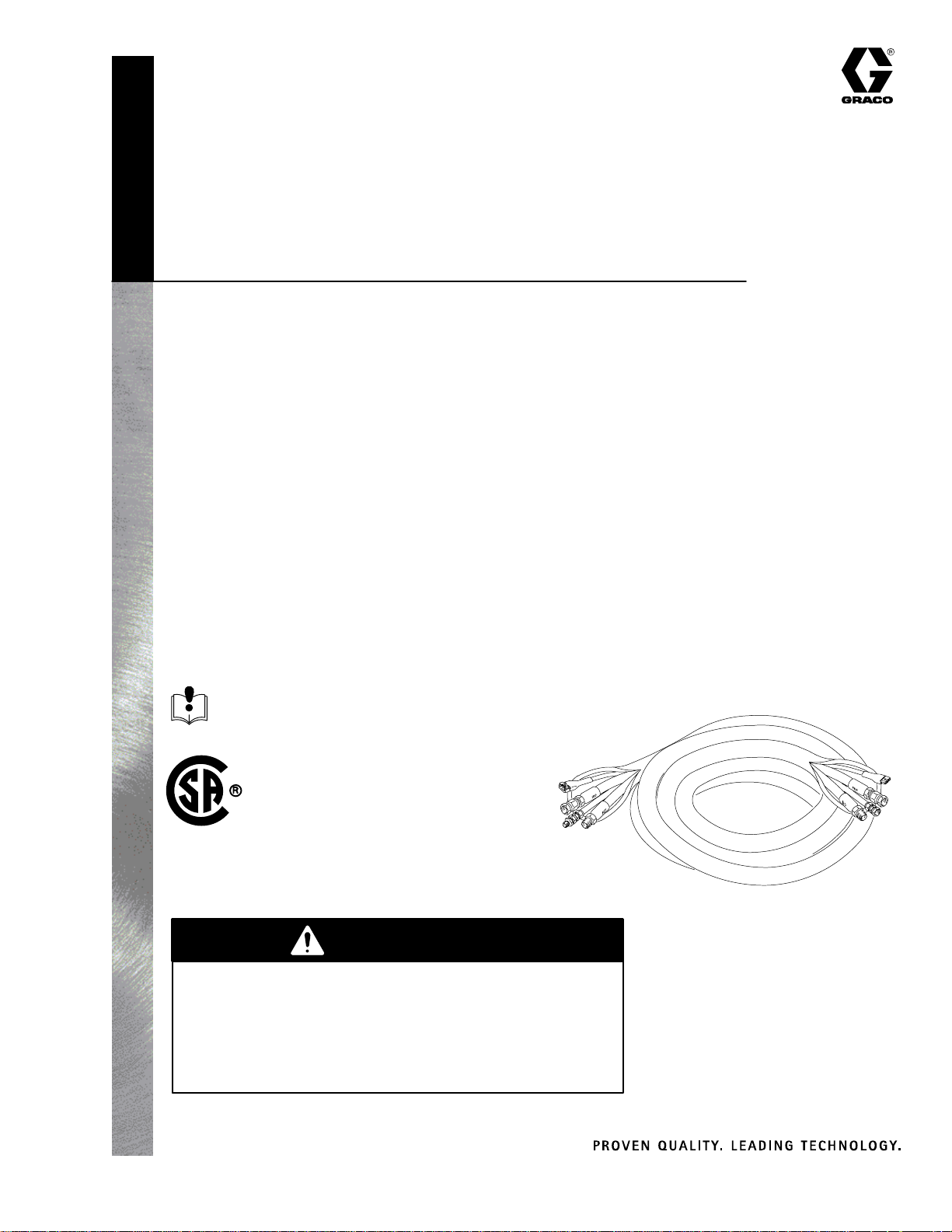
Foam-Catr Heated Hose
3000 psi (21 MPa, 207 bar) Maximum Working Pressure
Model 218613, Series B
50 foot (15.2 m) Hose, 3/8 in. ID
Model 218614, Series B
15 foot (4.6 m) Whip Hose, 1/4 in. ID
The heated hose maintains proper fluid temperature between the heater and gun
during spraying operations, and it raises the temperature of fluid left in the hose
when the heater is turned on after a shutdown period.
307544M
The Series B Heated Hoses include a 75_C (167_F) high limit thermostat. This
limits the maximum temperature to less than the 82_C (180_F) rating of the hoses,
allowing use at a full 3000 psi (21 MPa, 207 bar) pressure rating.
U.S. Patent No. 4,725,713
United Kingdom Patent No. 2,138,601
Brevete 1986 Canada
Read warnings and instructions.
See page 2 for table of contents.
CSA certified for use with Models
235259, Series B, 235839, Series B,
235260, Series B, and 235840, Series B
Foam-Cat Heaters.
Model 218613
WARNING
FIRE, EXPLOSION, AND ELECTRIC SHOCK HAZARD
The operating and safety features of these hoses are
designed for use only with the Graco Foam-Catr Heater and
Heater Hose Controls: Models 235259, 235839, 235260, and
235840. To reduce the risk of serious injury, never connect
these hoses to any other device.
GRACO INC.ąP.O. BOX 1441ąMINNEAPOLIS, MNą55440-1441
Copyright 1982, Graco Inc. is registered to I.S. EN ISO 9001
Page 2
Table of Contents
Introduction 2. . . . . . . . . . . . . . . . . . . . . . . . . . . . . . . . . . . . . . . . . . . . . .
Symbols 2. . . . . . . . . . . . . . . . . . . . . . . . . . . . . . . . . . . . . . . . . . . . . . . . .
Warnings 3. . . . . . . . . . . . . . . . . . . . . . . . . . . . . . . . . . . . . . . . . . . . . . . .
Installation 5. . . . . . . . . . . . . . . . . . . . . . . . . . . . . . . . . . . . . . . . . . . . . . .
Operation and Maintenance 9. . . . . . . . . . . . . . . . . . . . . . . . . . . . . . . .
Parts 10. . . . . . . . . . . . . . . . . . . . . . . . . . . . . . . . . . . . . . . . . . . . . . . . . . .
Technical Data 11. . . . . . . . . . . . . . . . . . . . . . . . . . . . . . . . . . . . . . . . . . .
Graco Warranty 12. . . . . . . . . . . . . . . . . . . . . . . . . . . . . . . . . . . . . . . . . .
Graco Phone Number 12. . . . . . . . . . . . . . . . . . . . . . . . . . . . . . . . . . . .
Introduction
Understanding how the Foam Catr Heater functions
and how to adjust it properly for your application conditions, is the key to easy operation and early detection
of possible equipment problems.
Read this manual and the manuals for all of the
components in your spray system thoroughly before
installing or operating the equipment.
Reference letters and numbers
Reference numbers and letters in parentheses in the
text refer to the illustrations or the parts drawings.
Information on parts referenced with letters can usually
be found in the separate instruction manuals accompanying those components.
Symbols
Warning Symbol
WARNING
This symbol alerts you to the possibility of serious
injury or death if you do not follow the instructions.
Terms
RES and ISO refer to the foam chemicals Resin and
Isocyanate, respectively.
Ambient Temperature is the surrounding air temperature.
ATC is the optional Ambient Temperature Compensator feature of the Foam-Cat Heater.
Caution Symbol
CAUTION
This symbol alerts you to the possibility of damage to
or destruction of equipment if you do not follow the
instructions.
2 307544
Page 3
INSTRUCTIONS
WARNING
EQUIPMENT MISUSE HAZARD
Equipment misuse can cause the equipment to rupture or malfunction and result in serious injury.
D This equipment is for professional use only.
D Read all instruction manuals, tags, and labels before operating the equipment.
D Use the equipment only for its intended purpose. If you are uncertain about usage, call your Graco
distributor.
D Use the hose only with the Graco Foam-Catr Heater and Heater Hose Controls: Models 235259,
235839, 235260, and 235840.
D Do not alter or modify this equipment. Use only genuine Graco parts and accessories.
D Check equipment daily. Repair or replace worn or damaged parts immediately.
D Do not exceed the maximum working pressure of the lowest rated system component. This equip-
ment has a 3000 psi (21 MPa, 207 bar) maximum working pressure.
D Route hoses away from traffic areas, sharp edges, moving parts, and hot surfaces.
D To avoid excessive heat buildup, never operate the hose when it is coiled.
D Do not use the hoses to pull the equipment.
D Use fluids and solvents that are compatible with the equipment wetted parts. Refer to the Techni-
cal Data section of all equipment manuals. Read the fluid and solvent manufacturer’s warnings.
D Comply with all applicable local, state, and national fire, electrical, and safety regulations.
TOXIC FLUID HAZARD
Hazardous fluid or toxic fumes can cause serious injury or death if splashed in the eyes or on the skin,
inhaled, or swallowed.
D Know the specific hazards of the fluid you are using.
D Store hazardous fluid in an approved container. Dispose of hazardous fluid according to all local,
state and national guidelines.
D Always wear protective eyewear, gloves, clothing and respirator as recommended by the fluid and
solvent manufacturer.
D Graco does not manufacture or supply any of the reactive chemical components that may be used
in this equipment and is not responsible for their effects. Graco assumes no responsibility for loss,
damage, expense or claims for personal injury or property damage, direct or consequential, arising
from the use of such chemical components.
Continued on the next page.
3307544
Page 4
WARNING
INJECTION HAZARD
Spray from the gun, hose leaks, or ruptured components can inject fluid into your body and cause
extremely serious injury, including the need for amputation. Splashing fluid in the eyes or on the skin
can also cause serious injury.
D Fluid injected into the skin might look like just a cut, but it is a serious injury. Get immediate medi-
cal attention.
D Do not point the spray gun at anyone or at any part of the body.
D Do not put your hand or fingers over the spray tip/nozzle.
D Do not stop or deflect leaks with your hand, body, glove or rag.
D Do not “blow back” fluid; this is not an air spray system.
D Always have the trigger guard on the spray gun when spraying.
D Be sure the gun trigger safety operates before spraying.
D Lock the gun trigger safety when you stop spraying.
D Follow the Pressure Relief Procedure on page 9 whenever you: are instructed to relieve pres-
sure; stop spraying; clean, check, or service the equipment; and install or clean the spray tip/
nozzle.
D Tighten all fluid connections before operating the equipment.
D Check the hoses, tubes, and couplings daily. Do not mend or repair any part of the hose assembly.
If the hose is damaged, replace it immediately.
FIRE, EXPLOSION, AND ELECTRIC SHOCK HAZARD
Improper grounding, poor ventilation, open flames, or sparks can cause a hazardous condition and
result in fire, explosion, electric shock or other serious injury.
D Ground the equipment and the object being sprayed according to the system component manuals
and local code.
D All electrical wiring must be done by trained and qualified personnel and comply with all local codes
and regulations.
D Do not use the hose until the couplings are properly insulated and the hose abrasion cover is in
place.
D Do not expose the hose to rain.
D Provide fresh air ventilation to avoid the buildup of flammable fumes from solvents or the fluid
being sprayed.
D Keep the spray area free of debris, including solvent, rags, and gasoline.
D If there is any static sparking while using the equipment, stop spraying immediately. Identify and
4 307544
correct the problem.
Page 5

Installation
Each hose assembly is 50 feet (15 m) long. A maximum combined length of 300 feet (92 m) can be used,
in addition to a 15 foot (4.6 m) whip hose assembly.
The whip hose assembly is smaller in diameter, which
makes maneuvering the hose easier for the operator.
The fluid hoses are marked ISO or RES and are
oppositely coupled to prevent incorrect connection,
which can cause fluid crossover and permanently
damage the hose. Refer to Fig. 1.
WARNING
ELECTRIC SHOCK HAZARD
Strain on the heat tape wires can pull
them loose from the connectors when
the hose is moved or coiled. To reduce
the risk of an electric shock from loose or damaged
wires, follow these precautions.
D Make the bend in the heat tape as instructed
below.
D Do not wrap the heat tape around the hoses.
Connecting the 50 foot (15.2 m) Hoses
a. Slide the male end of the sleeve (A) over the
hose (B).
b. Grease the barbed end of the stud (C) and
push it into the hose until it seats properly.
c. Tighten the sleeve until it bottoms on the
fitting.
d. Connect the air hose.
1
Connect RES and ISO hoses.
2
Bend the slack in heat tape
3
Couple heat tape connector
3
1
2
Fig. 1
04439A
1. Connect the corresponding fluid hoses of each 50
foot (15.2 m) assembly. See Fig. 1.
2. Gently bend the slack in the heat tape on both
sides of the tape connectors as shown in Fig. 1.
3. Couple the heat tape connectors.
4. Cut the uncoupled air hoses (B) to a length that
will be easy to couple to the next air hose. See
Fig. 2.
5. Attach a coupling to the air hose.
Fig. 2
A
B
C
04440
5307544
Page 6

Installation
6. Check the continuity of the heat tapes.
a. Use an ohmmeter to check the electrical
resistance of the two outer prongs of the
connector (D) that attaches to the heated hose
control. See Fig. 3. The resistance for the
various lengths of coupled hose assemblies is
given in the following coupled hose chart.
Coupled Hose Length
315 feet (96 m)
215 feet (66 m)
115 feet (35 m)
65 feet (20 m)
50 feet (15.2 m)
Resistance Range
11–15 ohms
20–25 ohms
37–46 ohms
65–80 ohms
84–124 ohms
b. Between the middle and outer prong of the
connector, the resistance should be more than
1 megohm. If it is less, there is a fault in one of
the connectors (D) or the heat tapes, which
will cause the Ground Fault Interrupter of the
Foam-Cat Heater hose control to shut off
electric power to the hose. If there is a fault,
check each 50 foot (15.2 m) hose section
individually and replace the faulty section.
c. Check the continuity of the middle prong of the
connector (D) from one end of the coupled
hoses to the other. The resistance should be
less than 10 ohms.
7. Connect the whip hose to the main hose assembly.
a. Connect the corresponding fluid hoses.
b. Connect the hose electrical connector to the
control box cable.
c. Connect the air hoses. Do not alter the air
hose length at this connection. Loop it down
from the gun as shown in Fig. 4.
Loop the air hose
1
1
Fig. 4
06421
8. Check all hose connections to be sure they are
securely tightened.
9. Connect the main hose(s) to the heater and the
whip hose to the gun.
10. Ground the system.
d. Check the continuity of the whip hose between
the two outer prongs and then between the outer
and middle prongs of the exposed connector as
instructed in steps 6a. and 6b. The resistance
between the outer prongs should be 300 to 400
ohms.
1
Outer prong
2
Middle prong
1
D
2
Fig. 3
04441
WARNING
FIRE, EXPLOSION, AND ELECTRIC
SHOCK HAZARD
Before operating the system, ground it
as explained in your separate component manuals and local code. Also read
the section FIRE, EXPLOSION, AND
ELECTRIC SHOCK HAZARD, page 4.
The Foam-Cat Heated Hose is grounded through
connection to a properly grounded Foam-Cat
Heater. In a mobile installation, be sure the truck
or trailer is grounded to a true earth ground.
In Europe, the hose continuity must comply with
VDE 0100.
6 307544
Page 7

Installation
WARNING
INJECTION HAZARD
To reduce the risk of serious injury,
follow the Pressure Relief Procedure
on page 9 whenever you are instructed
to relieve pressure.
11. Pressure check the hose assemblies. Refer to the
heater manual 308219 for priming and pressurizing
the fluid hoses. Check carefully for leaks at the
hose connections. If there are leaks, relieve the
pressure as instructed on page 9. Tighten the
connections, then pressurize the sprayer and
hoses again to make sure the leaks have stopped.
Shut off the sprayer and relieve the pressure.
12. Insulate the hose connections.
a. Wrap electrical tape securely around the fluid
and air hose connectors only, so the sharp
metal edges of the connectors cannot damage
the plastic connectors of the heat tapes. See
Fig. 5.
b. Tape the heat tape connectors together sepa-
rately to help prevent the connectors from
pulling apart. Then tape the heat tape connectors to the air and fluid hose connectors; leave
the wires free to move slightly to prevent strain
on the wires at the connectors. See Fig. 6.
c. Wrap the insulation tubing (E) around the hose
connections, overlapping at the seam. See
Fig. 7. Wrap the tape (F) continuously around
the tubing, beginning and ending about 2 inches
(51 mm) past the slit in the insulation.
1
Wrap hose connections with electrical tape
Fig. 5
1
Tape heat tape connectors to hose connections with electrical tape
Fig. 6
E
1
04453A
1
04454A
F
NOTE: Standard black electrical tape can be used if
additional tape is needed to secure the tubing.
WARNING
To reduce the risk of serious injury, including fluid
injection or electric shock:
D Do not use the heated hoses for spray-
ing without the insulation tubing in
place (see Step 12) and the abrasion
cover installed (see Step 13).
D Replace the insulation immediately if
any portions of it are worn away.
Fig. 7
7307544
Page 8

Installation
13. To install the cover:
a. Lay the abrasion cover (G) and assembled
heated hose (H) end to end. Refer to Fig. 8.
b. With the gun disconnected from the gun man-
ifold (J) and the air hose disconnected from the
gun, pull a couple of inches of the cover (G) over
the manifold and hoses and tape the cover to the
hoses.
c. Push the cover (G) onto the hoses. See Fig. 8.
The cover will double over itself and be turned
inside out as it slides over the hoses.
d. Secure the other end of the cover (G) with
tape.
GHJ
Fig. 8
14. Install hose abrasion cover before spraying. The
abrasion cover protects the heated hose from
damage caused by rough surfaces. It also minimizes heat loss and protects the couplings from
damage. Order part no. 070411 and specify the
total length of your hose times 1.25.
04456
8 307544
Page 9

Operation and Maintenance
Pressure Relief Procedure
WARNING
INJECTION HAZARD
The system pressure must be manually
relieved to prevent the system from
starting or spraying accidentally. Fluid
under high pressure can be injected through the
skin and cause serious injury. To reduce the risk of
an injury from injection, splashing fluid, or moving
parts, follow the Pressure Relief Procedure
whenever you:
D are instructed to relieve the pressure,
D stop spraying,
D check or service any of the system equipment,
D or install or clean the spray tip/nozzle.
1. Lock the gun trigger safety.
2. Shut off the air to the feed pumps.
9. If you suspect that the spray tip/nozzle or hose is
completely clogged, or that pressure has not been
fully relieved after following the steps above, very
slowly loosen the tip/nozzle retaining nut or hose
end coupling to relieve pressure gradually, then
loosen completely. Wear protective gloves to avoid
skin injection or burns. Now clear the tip/nozzle or
hose.
10. Be sure the fluid is cool before disconnecting the
hoses.
Operation
WARNING
INJECTION HAZARD
Never operate the hose when it is coiled.
A coiled hose creates excessive heat
buildup which can result in hose rupture
and cause serious injury, including injection. The
high heat can also cause poor foam development.
Refer to your system manual for complete startup and
operating instructions.
3. Turn off the power (air or electric motor switch) to
the proportioning pump.
4. Close the gun manifold fluid valves.
5. Unlock the spray gun trigger safety.
6. Hold a metal part of the gun firmly to the side of a
grounded metal pail, then trigger the gun to relieve
pressure.
7. Lock the trigger safety again.
8. Open both fluid filter drain valves; have a container
ready to catch the draining fluid.
Maintenance
WARNING
INJECTION HAZARD
Do not mend or repair any part of a hose
assembly. If the hose is damaged,
replace it immediately to avoid serious
injury from fluid injection and electric shock.
If a section of hose is not heating, be sure the connector at the hose control box is firmly plugged in. If that
does not correct the problem, relieve the fluid pressure
in the sprayer and hoses, as instructed at left. Remove
the abrasion cover and the insulation tubing on each
end of the hose in question. Make sure the heat tape
connections are secure and repeat the continuity
check in Step 6, page 6. If the hose is faulty or the
problem not corrected, replace the hose.
9307544
Page 10

Parts
Model 218613, Series B
50 foot (15.2 m) Hose.
Replaceable parts include items 1–4 only.
Ref.
No. Part No. Description Qty.
1 178540 TUBE, insulation, 50 ft. (15.2 m) 1
2 205447 COUPLING, 1/4 npt(m x f) 2
3 156173 UNION, adapter,
3/8 swivel x 3/8 npt(f) 2
4 162453 NIPPLE, 1/4 npsm x 1/4 npt 1
3
1
2
4
3
2
Model 218614, Series B
15 foot (4.6 m) Hose.
Replaceable parts include items 1–4 only.
Ref.
No. Part No. Description Qty.
1 162453 NIPPLE, 1/4 npsm x 1/4 npt 2
2 104415 COUPLER, hose 2
3 157350 NIPPLE, reducing,
3/8 x 1/4 npt(mbe) 2
4 156173 UNION, adapter,
3/8 swivel x 3/8 npt(f) 1
3
4
3
2
1
2
1
06971
10 307544
Page 11

Technical Data
Maximum Working Pressure 3000 psi. . . . . . . . . . . . . .
(210 MPa, 207 bar)
Wattage 12 Watts/foot (39.4 Watts/meter). . . . . . . . . . .
at 240 VAC, 50/60 cycle
Wetted Parts Nylon; Steel, zinc or. . . . . . . . . . . . . . . . .
cadmium plated; Carbon Steel, zinc plated
11307544
Page 12

Graco Standard Warranty
Graco warrants all equipment manufactured by Graco and bearing its name to be free from defects in material and workmanship on the
date of sale to the original purchaser for use. With the exception of any special, extended, or limited warranty published by Graco,
Graco will, for a period of twelve months from the date of sale, repair or replace any part of the equipment determined by Graco to be
defective. This warranty applies only when the equipment is installed, operated and maintained in accordance with Graco’s written
recommendations.
This warranty does not cover, and Graco shall not be liable for general wear and tear, or any malfunction, damage or wear caused by
faulty installation, misapplication, abrasion, corrosion, inadequate or improper maintenance, negligence, accident, tampering, or substitution of non-Graco component parts. Nor shall Graco be liable for malfunction, damage or wear caused by the incompatibility of
Graco equipment with structures, accessories, equipment or materials not supplied by Graco, or the improper design, manufacture,
installation, operation or maintenance of structures, accessories, equipment or materials not supplied by Graco.
This warranty is conditioned upon the prepaid return of the equipment claimed to be defective to an authorized Graco distributor for
verification of the claimed defect. If the claimed defect is verified, Graco will repair or replace free of charge any defective parts. The
equipment will be returned to the original purchaser transportation prepaid. If inspection of the equipment does not disclose any defect
in material or workmanship, repairs will be made at a reasonable charge, which charges may include the costs of parts, labor, and
transportation.
THIS WARRANTY IS EXCLUSIVE, AND IS IN LIEU OF ANY OTHER WARRANTIES, EXPRESS OR IMPLIED, INCLUDING BUT
NOT LIMITED TO WARRANTY OF MERCHANTABILITY OR WARRANTY OF FITNESS FOR A PARTICULAR PURPOSE.
Graco’s sole obligation and buyer’s sole remedy for any breach of warranty shall be as set forth above. The buyer agrees that no other
remedy (including, but not limited to, incidental or consequential damages for lost profits, lost sales, injury to person or property, or any
other incidental or consequential loss) shall be available. Any action for breach of warranty must be brought within two (2) years of the
date of sale.
Graco makes no warranty, and disclaims all implied warranties of merchantability and fitness for a particular purpose in connection
with accessories, equipment, materials or components sold but not manufactured by Graco. These items sold, but not manufactured
by Graco (such as electric motors, switches, hose, etc.), are subject to the warranty, if any, of their manufacturer. Graco will provide
purchaser with reasonable assistance in making any claim for breach of these warranties.
In no event will Graco be liable for indirect, incidental, special or consequential damages resulting from Graco supplying equipment
hereunder, or the furnishing, performance, or use of any products or other goods sold hereto, whether due to a breach of contract,
breach of warranty, the negligence of Graco, or otherwise.
FOR GRACO CANADA CUSTOMERS
The parties acknowledge that they have required that the present document, as well as all documents, notices and legal proceedings
entered into, given or instituted pursuant hereto or relating directly or indirectly hereto, be drawn up in English. Les parties reconnaissent avoir convenu que la rédaction du présente document sera en Anglais, ainsi que tous documents, avis et procédures judiciaires
exécutés, donnés ou intentés à la suite de ou en rapport, directement ou indirectement, avec les procedures concernées.
Graco Information
TO PLACE AN ORDER, contact your Graco distributor, or call this number to identify the distributor closest to you:
1–800–367–4023 Toll Free
All written and visual data contained in this document reflects the latest product information available at the time of publication.
Graco reserves the right to make changes at any time without notice.
International Offices: Belgium, Korea, Hong Kong, Japan
Sales Offices: Minneapolis, Detroit
GRACO INC. P.O. BOX 1441 MINNEAPOLIS, MN 55440–1441
www.graco.com
PRINTED IN USA 307544 05/1982, Revised 11/2003
12 307544
 Loading...