

Graco FinishPro CompPack Series, FinishPro CompPack 256850, FinishPro CompPack 25A445, FinishPro CompPack 256854 Repair Manual
Page 1
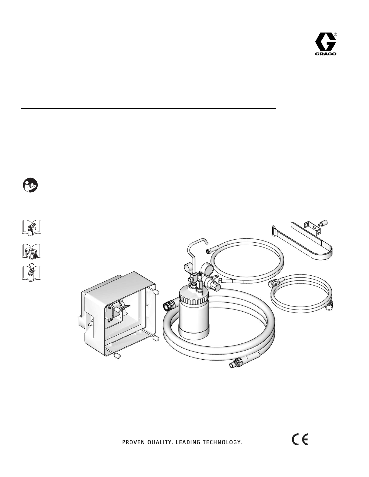
Repair
ti12757a
FinishPro CompPack Compressor
- For portable spray applications of fine finish coatings -
120 Vac Model: 256850
240 Vac Model: 256854, 25A445
Maximum Working Pressure: 10 psi (0,07 MPa, 0.7 bar)
Important Safety Instructions
Read all warnings and instructions in the sprayer
manual, 313406. Save these instructions.
313440E
EN
313317
313406
313441
Page 2
Setup
18
17
20
21
ti13061a
35
A
105
17
20
21
35
ti12857a
ti12798a
A
B
C
ti13082a
ti12797a
Setup
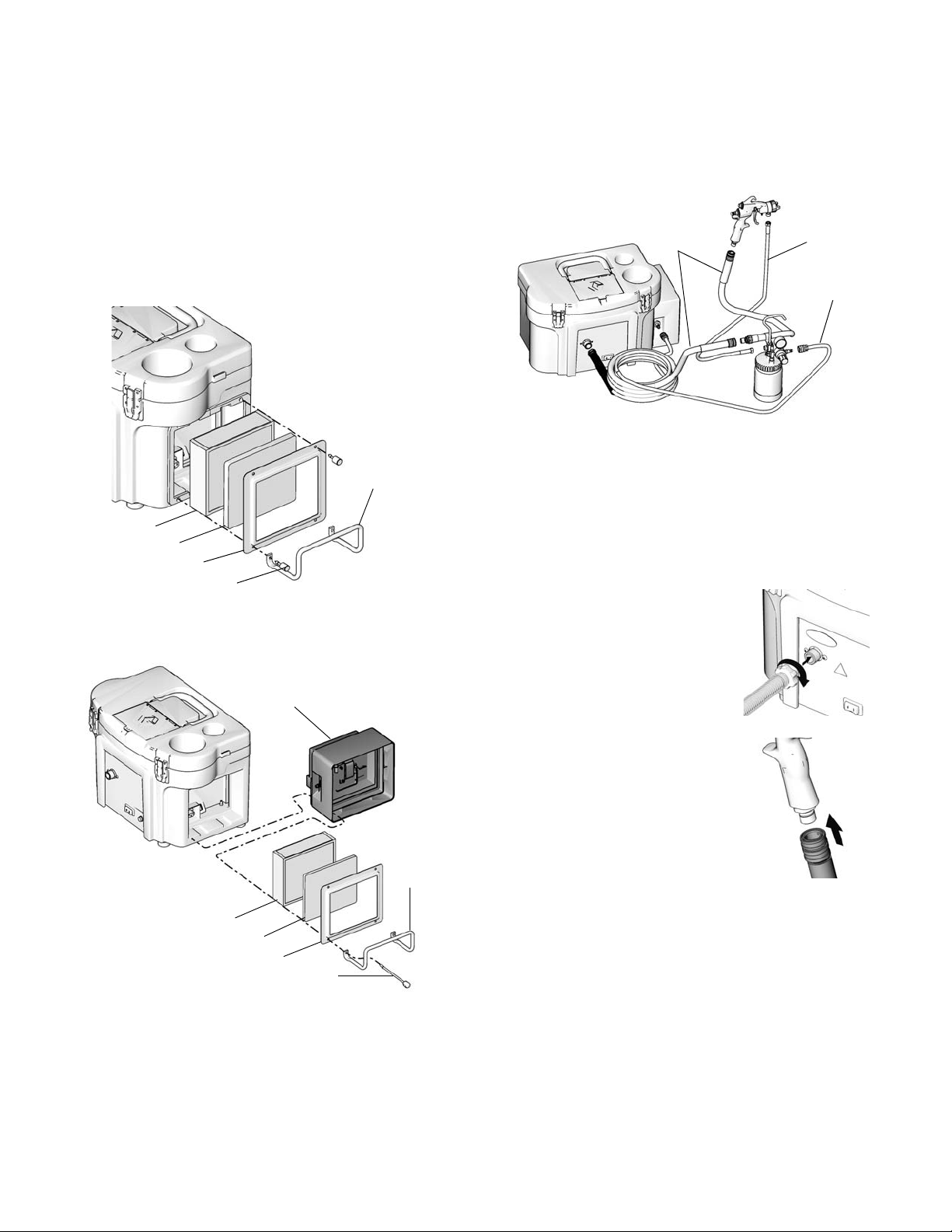
CompPack Installation
For references (1) - (99), see Parts, manual 313406. For
reference numbers(101) - (199) see Parts, page 7.
1. Turn off and unplug sprayer.
2. Loosen four screws (18), remove hose wrap (35), fil
ter retainer (17), pre-filter (20) and main filter (21).
4. Install main filter (21), pre-filter (20), filter retainer (17)
and hose wrap (35) with four screws (105).
Spray Gun with Optional Remote Cup
The optional remote cup comes with two hoses.
1. Connect the short hoses to their matching long
sprayer hoses.
2. Convert spray gun from siphon cup operation to
remote cup operation. See Convert Gun from
Siphon Cup to Optional Remote Cup.
3. Install CompPack (A) on sprayer.
3. Connect air hose (A) to sprayer.
Hand tighten. Do not connect
whip hose direct to sprayer.
Connect whip hose to gun end of
hose only.
4. Connect air hose (A) from
sprayer to inlet fitting of spray gun.
5. Connect air hose (B) between
CompPack outlet and remote cup
air inlet.
2 313440E
Page 3
Setup
ti13151a
ti13149a
ti13152a
ti12915a
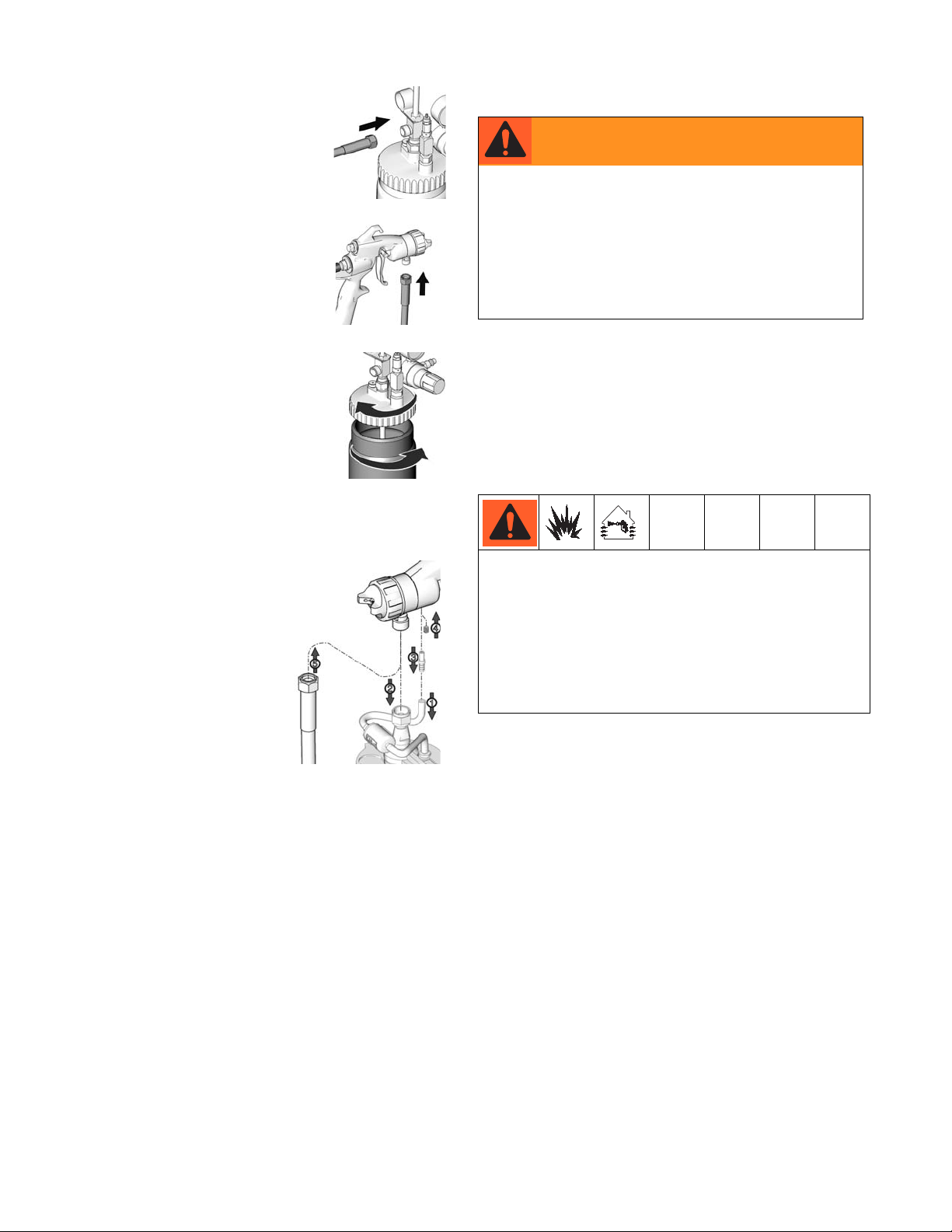
6. Connect fluid supply hose (C) from
remote cup fluid outlet to spray
gun fluid inlet.
7. Fill cup 3/4 full. Install cover.
Screw remote cup cover to secure
it to remote cup.
8. Refer to spray gun manual 313317
for spraying instructions.
Convert Gun from Siphon Cup to Optional
Remote Cup
Pressure Relief Procedure
WARNING
The optional remote cup remains pressurized
until pressure is manually relieved. To reduce
the risk of serious injury from pressurized fluid
or accidental spray from gun, always relieve
pressure in the remote cup before loosening
or removing the cover. Also, relieve pressure
if the fluid nozzle clogs; and before cleaning,
checking or servicing equipment.
1. Turn off sprayer.
2. Unplug sprayer.
3. Turn out pressure relief knob (113) one turn. Wait
until pressure is completely relieved before removing
cover. Close knob.
Operation Tips
1. Remove air pressure tube
from air stem.
2. Remove siphon cup cover
from gun
3. Remove air stem from gun.
4. Apply medium strength
thread locker to set screw.
Install set screw into gun
flush with gun body.
5. Connect fluid supply hose.
Note: To convert from remote cup to siphon cup, reverse
these instructions.
Connect to Electric Supply
Plug sprayer power cord into grounded o utlet. Grou ndin g
and Electric Requirements, page 4, manual 313406.
Sparks can be expected during normal operation of
motor. These sparks can ignite fumes from flammable
liquids, dust particles, and other flammable sub
stances in the spray area.
• Use additional hose if necessary, and ensure the
sprayer is operated in clean, dry, well ventilated
area.
• Never use sprayer inside spray booth.
• Turn sprayer On a few minutes before spraying to
allow warm-up.
• Ensure sprayer filter is clean before operating. Clean
filter, page 7, manual 313406.
• To adjust spray gun pattern, see HVLP EDGE Gun
manual 313317.
• To get proper adhesion, ensure surface is completely
clean.
• If the remote cup is accidentally tipped over or held at
too great of an angle, fluid may leak into air regulator
and cause damage. Take precautions to avoid this. If
fluid does get into regulator, clean immediately.
• Only hand-tighten remote cup cover. Excessive tight
ening may damage cover gasket.
• Always spray with the least amount of pressure
required to provide the desired spray p attern and rate
of application, typically 10 psi. Spraying at pressures
higher than necessary wastes paint and can result in
an orange peel finish.
• Lightly coat cover threads with petroleum jelly.
313440E 3
Page 4

Repair
A
105
17
20
21
35
ti12857a
107
104
112
111
109
102
B
Repair
Compressor Removal
For references (1) - (99), see Parts, manual 313406. For
reference numbers(101) - (199) see Parts, page 7.
To avoid injury, including electric shock turn off
sprayer and unplug power cord befor e performing any
repair procedures.
1. Remove four thumbscrews (105) hose wrap (35),
remove filter retainer (17), prefilter (20), main filter
(16) and filter gaskets (19).
2. Remove CompPack Compressor (A).
4. Disconnect three spade connectors (B) from back of
inlet plug (102).
5. Remove three screws (104) from compressor box
(112) and remove compressor (111).
3. Remove air tube (107) from quick connector (109)
barb fitting.
Compressor Installation
1. Install compressor (111) in compressor box (112)
with three screws (104).
2. Connect three spade connectors (B) to back of inlet
plug (102).
3. Install air tube (107) on quick connector (109) barb fit
ting.
4. Install CompPack Compressor (A).
5. Install main filter (21), pre-filter (20), filter retainer (17)
and hose wrap (35) with four screws (105).
4 313440E
Page 5

Wiring Diagram
BK
W
G
ti13144a
Wiring Diagram
Technical Data
120 Vac, 60 Hz
Weight lb
Ampere Watts
CompPack
230 Vac, 50 Hz
CompPack
* Sound Power and Sound Pressure are measured at 1 meter per ISO 3744.
1.5 80 5 (2,7) 79.2 dBa 67.2 dBa
Ampere Watts
0,8 80 5 (2,7) 79.2 dBa 67.2 dBa
(kg)
Weight lb
(kg)
Sound
Power*
Sound
Power*
Sound
Pressure*
Sound
Pressure*
313440E 5
Page 6

Parts Drawing
ti12908b
102
101
103
104
Models: 256850, 256854
Parts Drawing
Parts List
Models: 256850, 256854
Ref Part Description Qty
101 15Y858 KIT, compressor box HVLP, 120V 1
102 257098 KIT CUP, 1 qt complete 1
103 240488 COMPRESSOR, hose 1
104 256959 STRAP, remote, cup 1
6 313440E
15Y859 KIT, compressor box HVLP, 240V 1
Page 7

Parts Drawing
103
110
109
107
106
105
102
101
108
ti27709a
Models: 25A445
Parts Drawing
Parts List
Models: 25A445
Ref Part Description Qty
101 15Y859 KIT, compressor 1
102 24Y630 GUN, HVLP, no cup 1
103 240475 HOSE, fluid 1
104 25A433 KIT, repair, 1 qt cup 1
105 17J918 HOSE, air 1
106 17H702 HOSE, air 1
107 257161 HOSE, whip 1
108 114958 STRAP, tie 11
109 240065 VALVE, air control 1
110 M70402 FITTING, female, Q.D. 1
313440E 7
Page 8

Graco Standard Warranty
Graco Standard Warranty
Graco warrants all equipment referenced in this document which is manufactured by Graco and bearing its name to be free from defects in material
and workmanship on the date of sale to the original purchaser for use. With the exception of any special, extended, or limited warranty published by
Graco, Graco will, for a period of twelve months from the date of sale, repair or replace any part of the equipment determined by Graco to be
defective. This warranty applies only when the equipment is installed, operated and maintained in accordance with Graco’s written recommendations.
This warranty does not cover, and Graco shall not be liable for general wear and tear, or any malfunction, damage or wear caused by faulty
installation, misapplication, abrasion, corrosion, inadequate or improper maintenance, negligence, accident, tampering, or substitution of non-Graco
component parts. Nor shall Graco be liable for malfunction, damage or wear caused by the incompatibility of Graco equipment with structures,
accessories, equipment or materials not supplied by Graco, or the improper design, manufacture, installation, operation or maintenance of structures,
accessories, equipment or materials not supplied by Graco.
This warranty is conditioned upon the prepaid return of the equipment claimed to be defective to an authorized Graco distributor for verification of the
claimed defect. If the claimed defect is verified, Graco will repair or replace free of charge any defective parts. The equipment will be returned to the
original purchaser transportation prepaid. If inspection of the equipment does not disclose any defect in material or workmanship, repairs will be made
at a reasonable charge, which charges may include the costs of parts, labor, and transportation.
THIS WARRANTY IS EXCLUSIVE, AND IS IN LIEU OF ANY OTHER WARRANTIES, EXPRESS OR IMPLIED, INCLUDING BUT NOT LIMITED
TO WARRANTY OF MERCHANTABILITY OR WARRANTY OF FITNESS FOR A PARTICULAR PURPOSE.
Graco’s sole obligation and buyer’s sole remedy for any breach of warranty shall be as set forth above. The buyer agrees that no other remedy
(including, but not limited to, incidental or consequential damages for lost profits, lost sales, injury to person or property, or any other incidental or
consequential loss) shall be available. Any action for breach of warranty must be brought within two (2) years of the date of sale.
GRACO MAKES NO WARRANTY, AND DISCLAIMS ALL IMPLIED WARRANTIES OF MERCHANTABILITY AND FITNESS FOR A
PARTICULAR PURPOSE, IN CONNECTION WITH ACCESSORIES, EQUIPMENT, MATERIALS OR COMPONENTS SOLD BUT NOT
MANUFACTURED BY GRACO. These items sold, but not manufactured by Graco (such as electric motors, switches, hose, etc.), are subject to the
warranty, if any, of their manufacturer. Graco will provide purchaser with reasonable assistance in making any claim for breach of these warranties.
In no event will Graco be liable for indirect, incidental, special or consequential damages resulting from Graco supplying equipment hereunder, or the
furnishing, performance, or use of any products or other goods sold hereto, whether due to a breach of contract, breach of warranty, the negligence of
Graco, or otherwise.
FOR GRACO CANADA CUSTOMERS
The Parties acknowledge that they have required that the present document, as well as all documents, notices and legal proceedings entered into,
given or instituted pursuant hereto or relating directly or indirectly hereto, be drawn up in English. Les parties reconnaissent avoir convenu que la
rédaction du présente document sera en Anglais, ainsi que tous documents, avis et procédures judiciaires exécutés, donnés ou intentés, à la suite de
ou en rapport, directement ou indirectement, avec les procédures concernées.
ADDITIONAL WARRANTY COVERAGE
Graco does provide extended warranty and wear warranty for products described in the “Graco Contractor Equipment Warranty Program”.
Graco Information
For the latest information about Graco products, visit www.graco.com.
For patent information, see www.graco.com/patents.
TO PLACE AN ORDER, contact your Graco distributor or call 1-800-690-2894 to identify the nearest distributor.
All written and visual data contained in this document reflects the latest product information available at the time of publication.
GRACO INC. AND SUBSIDIARIES • P.O. BOX 1441 • MINNEAPOLIS MN 55440-1441 • USA
Copyright 2009 Graco Inc. All Graco manufacturing locations are registered to ISO 9001.
8 313440E
Graco reserves the right to make changes at any time without notice.
For patent information, see www.graco.com/patents.
Original instructions. This manual contains English. MM 313440
Graco Headquarters: Minneapolis
International Offices: Belgium, China, Japan, Korea
www.graco.com
Revised E, November 2015
 Loading...