

Page 1

INSTRUCTIONS–PARTS
This manual contains important
warnings and information.
READ AND RETAIN FOR REFERENCE
1:1
INSTRUCTIONS
RA
TIO
LIST
307–427
Rev.
V
Supersedes U
Fast-Flo
Pump
12.4 bar (180 psi) Maximum Air Input Pressure
12.4 bar (180 psi) Maximum Fluid Working Pressure
Refer
to page 4 for a list of pump models.
Stubby Pump
03761
Table
Symbols 2.
Warnings 2
Pump
Installation 5
Operation 8
Maintenance 9
Troubleshooting 10
Pump
Pump
Displacement
Displacement
Accessories 36
Dimensions 38
Technical
Warranty 40
Graco
. . . . . . . . . . . . . . . . . . . . . . . . . . . . . . . . . . . . .
. . . . . . . . . . . . . . . . . . . . . . . . . . . . . . . . . . . . . .
Models4. . . . . . . . . . . . . . . . . . . . . . . . . . . . . . . . . .
. . . . . . . . . . . . . . . . . . . . . . . . . . . . . . . . . . . . .
Service
Parts
Data
. . . . . . . . . . . . . . . . . . . . . . . . . . . . . . . . . . . . .
Phone Numbers
of Contents
. . . . . . . . . . . . . . . . . . . . . . . . . . . . . . . . . . . .
. . . . . . . . . . . . . . . . . . . . . . . . . . . . . . . . . . .
. . . . . . . . . . . . . . . . . . . . . . . . . . . . . . .
. . . . . . . . . . . . . . . . . . . . . . . . . . . . . . . .
. . . . . . . . . . . . . . . . . . . . . . . . . . . . . . .
Pump Service
Pump Parts
. . . . . . . . . . . . . . . . . . . . . . . . . . . . . . . . . .
. . . . . . . . . . . . . . . . . . . . . . . . . . . . . . . . . . .
. . . . . . . . . . . . . . . . . . . . . . . . . . . . . . .
GRACO INC. P.O. BOX 1441
. . . . . . . . . . . . . . . .
. . . . . . . . . . . . . . . . . .
. . . . . . . . . . . . . . . . . . . . . . . .
11.
12–16.
17–32.
18–34.
39.
40.
COPYRIGHT
Adjustable Length Pump
MINNEAPOLIS, MN
1980, GRACO INC.
03783
Bung-Mounted
03761
Bung-Mounted
Drum Length Pump
55440–1441
Page 2
Symbols
Warning Symbol
WARNING
his
symbol alerts you to the possibility of serious
injury or death if you do not follow the instructions.
WARNING
WARNING
EQUIPMENT MISUSE HAZARD
INSTRUCTIONS
Equipment
D
This equipment is for professional use only
D
Read all instruction manuals, tags, and labels before operating the equipment.
D
Use the equipment only for its intended purpose. If you are not sure, call Graco T
tance at 1–800–543–0339.
D
Do not alter or modify this equipment.
misuse can cause the equipment to rupture or malfunction and result in serious injury
Caution Symbol
CAUTION
This
symbol alerts you to the possibility of damage to
or destruction of equipment if you do not follow the
instructions.
.
echnical Assis
.
-
D
Check equipment daily
D
Do not exceed the maximum working pressure of the lowest rated component in your system.
This equipment has a 12.4 bar (180 psi) maximum working pressure at 12.4 bar (180 psi)
maximum incoming air pressure.
D
Use fluids and solvents which are compatible with the equipment wetted parts. Refer to the
nical Data
ings.
D
Do not use hoses to pull equipment.
D
Route hoses away from traffic areas, sharp edges, moving parts, and hot surfaces. Do not ex
pose Graco hoses to temperatures above 82_C (180_F) or below –40_C (–40
D
Securely mount the pump. Do not attempt to operate it while holding it.
D
Do not lift pressurized equipment.
D
Comply with all applicable local, state, and national fire, electrical, and safety regulations.
section of all equipment manuals. Read the fluid and solvent manufacturer’s warn
. Repair or replace worn or damaged parts immediately
.
_F).
Tech-
-
-
Page 3

TOXIC FLUID HAZARD
WARNING
WARNING
Hazardous
skin, inhaled, or swallowed.
Know the specific hazards of the fluid you are using.
Store hazardous fluid in an approved container
state and national guidelines.
Any additives to the air supply
Always wear protective eyewear
and solvent manufacturer
fluid or toxic fumes can cause serious injury or death if splashed in the eyes or on the
. Dispose of hazardous fluid according to all local,
, such as oil or anti–freeze will be exhausted into the atmosphere.
, gloves, clothing and respirator as recommended by the fluid
.
FIRE AND EXPLOSION HAZARD
Improper
result in a fire or explosion and serious injury
grounding, poor ventilation, open flames or sparks can cause a hazardous condition and
.
Ground the equipment. Refer to
If there is any static sparking or you feel an electric shock while using this equipment,
pumping immediately. Do not use the equipment until you identify and correct the problem.
Provide fresh air ventilation to avoid the buildup of flammable fumes from solvents or the fluid
being sprayed.
Grounding the System
on page 5.
stop
Keep the work area free of debris, including solvent, rags, and gasoline.
Electrically disconnect all equipment in the work area.
Extinguish all open flames or pilot lights in the work area.
Do not smoke in the work area.
Do not turn on or of
Do not operate a gasoline engine in the work area.
f any light switch in the work area while operating or if fumes are present.
MOVING PARTS HAZARD
Moving
parts can pinch or amputate your fingers.
Keep clear of all moving parts when starting or operating the pump.
Before servicing the equipment, follow the
equipment from starting accidentally
Pressure Relief Procedure
.
on page 8 to prevent the
Page 4

Pump
PTFE
PTFE
PTFE
PTFE
Models
UL LISTED PUMPS
The
following pumps are UL listed for light viscosity
paints, lacquers, varnishes, thinners, solvents when
installed in accordance with NFP
tection Association) Standards No. 30, Flammable and
Combustible Liquids Code, and No. 33 Spray Finishing
Using Flammable Materials. The carbon steel pumps
are for non-corrosive fluids, and the stainless steel
pumps are for corrosives.
Stubby Pumps
Model
No.
226–943
Series B
226–944
Series B
*
226–945
Series B
*
Description
Carbon Steel,
Leather Packings
Carbon Steel,
Polyethylene
Packings
Stainless Steel,
Polyethylene
Packings
Bung-Mounted Drum Length Pumps
Model
No.
226–940
Series B
226–941
Series B
*
226–942
Series B
*
226–954
Series A
Description
Carbon Steel,
Leather Packings
Carbon Steel,
Polyethylene
Packings
Stainless Steel,
Polyethylene
Packings
Stainless Steel,
Leather Packings
*
A (National Fire Pro
Displacement
Pump No.
215–956
Series C
215–957
Series C
215–958
Series B
Displacement
Pump No.
215–953
Series D
215–954
Series D
215–955
Series B
236–991
Series A
Parts
Pages
14, 18
14, 19
15, 28
Parts
Pages
12, 18
12, 19
13, 27
13, 29
-
NON-LISTED PUMPS
These
pumps are for non-corrosive light viscosity fluids
such as anti-freeze, windshield washer solvent, A
TF,
motor oil, and hydraulic oil.
Stubby Pumps
Model
No.
226–948
Series B
226–952
Series B
Description
Carbon Steel,
Rubber Packings
Stainless Steel,
Rubber Packings
Displacement
Pump No.
218–114
Series A
220–439
Series A
Parts
Pages
14, 24
15, 34
Bung-Mounted Drum Length Pumps
Model
No.
226–947
Series B
226–951
Series B
226–953
Series B
Model 226–951 has a suction tube that can be extended
457 mm (18 in.). Non-extended pump length is 724 mm (28.5
in.). Fully extended pump length is 1
Description
Carbon Steel,
Rubber Packings
Carbon Steel,
Rubber Packings
Stainless Steel,
Rubber Packings
Displacement
Pump No.
218–113
Series A
218–116
Series A
220–440
Series A
180 mm (46.4 in.).
Parts
Pages
12, 24
16, 25
13, 33
NON-LISTED PUMPS
These
pumps are for general fluid transfer applica
tions.
Stubby Pumps
Model
No.
237–130
Series A
237–131
Series A
237–132
Series A
Description
Carbon Steel,
Leather Packings
Carbon Steel,
Packings
Stainless Steel,
Packings
Displacement
Pump No.
237–254
Series A
237–255
Series A
237–256
Series A
Bung-Mounted Drum Length Pumps
-
Parts
Pages
14, 20
14, 22
15, 31
Model
No.
237–133
Series A
237–134
Series A
237–129
Series A
Description
Carbon Steel,
Leather Packings
Carbon Steel,
Packings
Stainless Steel,
Packings
Displacement
Pump No.
215–953
Series D
237–449
Series A
237–253
Series A
Parts
Pages
12, 18
12, 21
13, 30
Page 5

General Information
Installation
1. The T
2.
3.
ypical Installation shown in Fig. 2 is only a
guide for selecting and installing system compo
nents. Contact your Graco distributor or Graco
T
echnical Assistance (1–800–543–0339) for assis
tance in planning a system to suit your needs.
Always use Genuine Graco Parts and Accesso
ries.
Reference numbers and letters in parentheses re
fer to the callouts in the figures and the parts lists
on pages 12–34.
Grounding the System
WARNING
FIRE
AND EXPLOSION HAZARD
This pump must be grounded. Before
operating the pump, ground the system
as explained below. Also, read the sec
tion
FIRE AND EXPLOSION HAZARD,
on page 3.
-
-
-
-
Fig. 1
2.
Air and fluid hoses
-
hoses.
Air compressor
3.
ommendations.
: use only electrically conductive
: according to manufacturer’s rec
Y
WXZ
03653
-
T
o reduce the risk of static sparking, ground the pump
and all other equipment used or located in the pumping
area. Check your local electrical code for detailed
grounding instructions for your area and type of equip
ment.
Ground all of this equipment.
1.
Pump
: connect a ground wire and clamp as shown
in Fig. 1. Loosen the grounding lug locknut (W)
and washer (X). Insert one end of a 12 ga (1.5
mm
) minimum ground wire (Y) into the slot in the
lug (Z) and tighten the locknut securely
the clamp end of the ground wire to a true earth
ground. Order Part No. 222–01
Clamp.
1 Ground Wire and
. Connect
4.
Dispensing valve:
connection to a properly grounded fluid hose and
pump.
-
5.
Fluid supply container:
6.
Object being sprayed:
7.
All solvent pails used when flushing
local code. Use only metal pails, which are con
ductive. Do not place the pail on a non-conductive
surface, such as paper or cardboard, which inter
rupts the grounding continuity
grounding is obtained through
according to local code.
according to local code.
, according to
-
-
.
Page 6

K
Installation
E
DF
JL
Model
226–951 only
DCC
EJ L
M
G
13 mm (0.5”)
H
C
B
A
C
KEY
A Vent
B
C
D
E
F
G
H
J
K
L
M
CC
Plug
Bung Adapter
Air Line Lubricator
Bleed-type Master Air V
Air Line Filter
Grounded Air Hose
Fluid Drain V
Fluid Outlet
Pin Fitting
Air Control V
(All Models except 226–951)
Air Line Coupler
Grounded Fluid Hose
Air Regulator Kit
(Model 226–951 only)
alve
alve
alve
Fig. 2
Mounting the Pump
Always
stallation planned. Graco mounting accessories are
shown in the
gallon) drum length pumps, screw the bung adapter
(B) tightly into the bung hole of the drum and adjust to
hold the pump 13 mm (0.5 in.) of
drum. Loosen the vent plug (A) to prevent formation of
a vacuum in the drum. Stubby pumps may be mounted
on a wall or on the side of a drum with a clamp. Drum
pumps can also be mounted to the side of a drum.
NOTE:
dimensions, and air inlet and fluid outlet sizes.
rigidly mount the pump to suit the type of in
Accessories
section. With 200 liter (55
f the bottom of the
Refer to
Dimensions
on page 38 for pump
-
03762
If low level cut-off valve 210–865 is being used, install
a drum length pump (except Model 226–951) in the
container with the valve 210–865 resting on the con
tainer bottom. This accessory valve will not fit pumps
with a telescoping suction tube, such as Model
226–951.
CAUTION
If low level cut-of
with a strap wrench to avoid damaging the valve.
Do not use the legs of the valve to tighten it into
the pump.
f valve 210–865 is used, install it
Page 7

Installation
System Accessories
Refer
to Fig. 2 and the Accessories section.
NOTE: T
sure that all accessories used are properly sized to
meet your system’
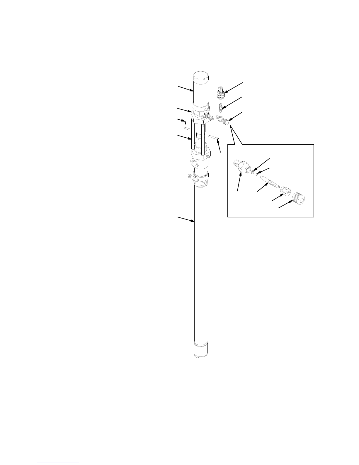
Most models are supplied with a needle-type air con
trol valve (K) at the pump air inlet. Model 226–951 is
equipped with an air regulator kit (CC) instead (see
Fig. 3). All models are supplied with an air line quick
disconnect coupler (L) to connect the air line to the
pump and accessories.
o ensure maximum pump performance, be
s requirements.
WARNING
A bleed-type master air valve (D) and a fluid drain
valve (G) are required in your system, to help re
duce the risk of serious injury
fluid in the eyes or on the skin, and injury from
moving parts if you are adjusting or repairing the
pump.
, including splashing
-
Model 226–951 Only
Using
moderate force, extend the pump suction tube,
insert the pump into the drum or tank bung hole, and
screw the bung adapter (B) tightly into the bung hole.
Lift the pump about 13 mm (0.5 in.) and tighten the
bung adapter (B) screw to hold the pump. Loosen the
vent plug (A). Refer to Fig. 2.
-
CAUTION
T
o prevent damaging the o-ring seals inside the
suction tube, do not use excessive force when ex
tending the suction tube.
All Other Models
Refer
to Fig. 2 and to the mounting accessories shown
on page 36 for pump mounting methods.
Model
226–951
Shown
-
The
bleed-type master air valve
trapped between this valve and the pump after the
pump is shut of
to cycle unexpectedly and result in serious injury
including amputation. Locate the valve close to the
pump.
The
fluid drain valve
the displacement pump, hose, and dispensing
valve when shutting of
dispensing valve to relieve pressure may not be
suf
ficient, especially if there is a clog in the hose or
the dispensing valve.
For automatic air motor lubrication, install an air line
lubricator (C) downstream from the air regulator (if
supplied) and all other accessories. Install a bleed-type
master air valve (D) close to the pump. Next, install the
air regulator (CC), if supplied. Install an air line filter (E)
upstream from all other accessories, to remove harm
ful dirt and moisture from the compressed air supply
Using a suitable adapter
pin fitting (J) in the air filter inlet. Install the air line
quick disconnect coupler (L) on the air hose (F), but do
not connect it to the pin fitting yet.
f. T
rapped air can cause the pump
(G) helps relieve pressure in
f the pump. Actuating the
, install the male disconnect
(D) relieves air
,
-
.
CC
JL
B
Connect an electrically conductive fluid hose (M) to the
3/4 npt(f) fluid outlet.
03763
Fig. 3
Page 8

Operation
Pressure Relief Procedure
WARNING
PRESSURIZED
The equipment stays pressurized until pressure is
manually relieved. To reduce the risk of serious
injury from pressurized fluid, accidental spray from
the gun or splashing fluid, follow this procedure
whenever you:
Are instructed to relieve pressure,
Have an air supply interruption,
Stop pumping,
Check, clean or service any system equipment,
Install or clean fluid nozzles.
1.
Shut of
2.
Close the bleed-type master air valve (required in
your system).
3.
Hold a metal part of the dispensing valve firmly to
the side of a grounded metal pail, and trigger the
valve to relieve pressure.
4.
Open the fluid drain valve (required in your sys
tem) to relieve all fluid pressure, having a contain
er ready to catch the drainage.
5.
Leave the drain valve open until you are ready to
dispense again.
If you suspect that the nozzle or hose is completely
clogged, or that pressure has not been fully relieved
after following the steps above,
hose end coupling and relieve pressure gradually
loosen completely
EQUIPMENT HAZARD
f the air to the pump.
very slowly
. Now clear the nozzle or hose.
-
loosen the
, then
Cycle the pump slowly for at least 5 minutes, then stop
and disconnect the air hose. Push up on the ball of the
intake valve (N) to drain the lower part of the pump.
See Fig. 4. T
of the pump.
Fig. 4
urn the pump over to drain the upper part
N
03765
Starting and Adjusting the Pump
With
the air valve (K) or regulator (CC) closed, turn on
the air supply and connect the air line coupler (L). See
Figs. 3 or 5. Make sure all dispensing valves are open.
Slowly open the air valve (K) or regulator (CC) until the
pump cycles 5 to 20 cycles per minute. The pump it
self only takes a few strokes to prime. In a large sys
tem, however
-
several minutes to fill all the lines. Once the entire sys
tem is primed, use the air valve or regulator to control
pump speed and cycle rate; always use the lowest
pressure necessary to get the desired results.
When used for transfer and supply operations with no
dispensing valve, the pump will run whenever air is
supplied.
, the pump may have to be cycled for
-
-
-
Pump Shutdown
Flush the Pump Before Using
The
pump was tested in lightweight oil, which was left
in to protect pump parts. T
the fluid you are pumping, flush the pump with a com
patible solvent before using it.
T
o flush the pump, connect a short hose to the pump
outlet, insert the pump intake into a pail of compatible
solvent, direct the hose into a pail, and start the pump
as explained at right.
o prevent contamination of
WARNING
To
reduce the risk of serious injury whenever you
-
are instructed to relieve pressure, always follow the
Pressure Relief Procedure
1.
Disconnect the air line coupler (L).
2.
Relieve the pressure.
at left.
Page 9

Maintenance
Fill the wet-cup (P) 1/2 full of Graco Throat Seal Liquid
(TSL) or compatible solvent and keep it 1/2 full to keep
fluid from drying on the displacement rod and damag
ing pump throat packings. See Fig. 5.
Lubricate the throat packings frequently when you are
pumping a non-lubricating fluid, or are shutting down
for more than a few days. Some pumps have a grease
fitting (DD) for this purpose. See Fig. 5.
-
WARNING
T
o reduce the risk of serious injury whenever you
are instructed to relieve pressure, always follow the
Pressure Relief Procedure
on page 8.
WARNING
The accessory air line lubricator (C) provides automat
ic air motor lubrication. T
tor
, disconnect the air line at the air motor inlet, put
about 15 drops of lightweight oil in the inlet, reconnect
the air line and turn on the air to blow oil into the motor
Never allow the pump to run dry of fluid being pumped.
A dry pump will quickly accelerate to a high speed,
possibly damaging itself. If your pump accelerates
quickly
, or is running too fast, stop it immediately and
check the fluid supply
and air has been pumped into the lines, prime the
pump and lines with fluid, or flush and leave filled with
compatible solvent. Be sure to eliminate all air from the
fluid system.
o manually lubricate the mo
. If the supply container is empty
-
-
.
Do not attempt to adjust the packing nut with the
pump operating.
Periodically
Relieve the pressure, then tighten enough to prevent
leakage; no tighter
be stopped, change the packings to prevent exposure
to the fluid being pumped.
, check the tightness of the packing nut (P).
. See Fig. 5. If the leakage can not
L
J
K
P
H
DD
03764
Fig. 5
Page 10

Troubleshooting
1.
Relieve the pressure.
WARNING
2.
T
o reduce the risk of serious injury whenever you
are instructed to relieve pressure, always follow the
Pressure Relief Procedure
PROBLEM CAUSE SOLUTION
on page 8.
Check all other possible remedies before disas
sembling the pump.
-
The pump fails to operate.
The pump operates, but the output
low on both strokes.
is
The pump operates, but the output
low on the downstroke.
is
The pump operates, but the output
low on the upstroke.
is
Erratic or accelerated operation.
Dirty or worn air motor
Inadequate air supply or restricted
lines.
Closed or clogged air valves.
Clogged fluid hose or valve.
W
orn or damaged valves or seals.
Clogged fluid hose or valve.
Exhausted fluid supply
Worn
or damaged valves or seals.
Held open or worn intake valve.
W
orn or damaged valves or seals.
Held open or worn piston valve.
W
orn or damaged valves or seals.
Exhausted fluid supply
. Clean,
. Refill the fluid supply and reprime the
. Refill the fluid supply and reprime the
service; see the separate
manual
Clean lines or increase the air supply
(see T
Open or clear the valves.
Clear the hose or valves.
Service the valves or seals.
Clear the hose or valves.
pump.
Service the valves or seals.
Clear or service the valve.
Service the valves or seals.
Clear or service the valve.
Service the valves or seals.
pump.
307–456.
echnical Data).
motor
Broken
10 307-427
air motor compression
spring.
Replace
the spring.
Page 11

Disconnecting the Air Motor
WARNING
Pump
Service
To
reduce the risk of serious injury whenever you
are instructed to relieve pressure, always follow the
Pressure Relief Procedure
1.
Flush the pump.
2.
Relieve the pressure. Remove the pump from its
mounting.
3.
See Fig. 6. Unscrew the tie rod locknuts (103).
4.
Remove the clip pin (105) and headed pin (104).
5.
Raise the air motor (1
ment pump (1
(15) from the air motor connecting rod (S).
6. T
o order pump parts, refer to the parts lists on
pages 12–16. Refer to pages 17–34 for displace
ment pump service and parts information. Refer to
manual 307–456 for air motor service and parts
information.
14). Unscrew the displacement rod
on page 8.
15) away from the displace
Reconnecting the Air Motor
115
103
3
105
-
-
106
2
S
104
T
14
1. When
2.
3. T
4.
NOTE:
pump flow rate and exhaust noise.
5.
reconnecting the air motor
grease on the threads of the displacement rod
(15). Make sure the o-ring (14) is in place on the
rod.
Insert the muf
rod (S) as shown in Fig. 6.
ighten the displacement rod (15) into the air mo
tor connecting rod hand tight, and install the pins
(104 and 105).
Apply thread sealant to the threads of the tie rods
(106). T
tie rod locknuts (106) loosely onto the tie rods,
then torque evenly to 15 N.m (8 ft–lb).
Removing the muf
Reconnect the groundwire if it was disconnected
during service.
fler (T) into the air motor connecting
o ensure proper alignment, first thread the
fler (T) will increase both
, use lithium base
15
1
114
-
Grease
1
2
3
Fig. 6
the threads.
Apply thread sealant.
T
orque evenly to
15 N.m (8 ft–lb).
03766
307-427 11
Page 12
Pump
PTFE
Bung Mount Drum-Length Pumps,
Carbon Steel Models
Model
226–940, Series B,
Model 226–941, Series B,
Model 226–947, Series B,
Model 237–133, Series A,
Model 237–134, Series A,
Ref.
No.
103 104–541 NUT
104 178–923
105 180–166
106 177–171
107 190–165
108 206–264
109 157–628 . P
110 165–722 . BODY 1
111 166–531 .
112 166–529 . NEEDLE 1
113 190–164
114 215–953
115 223–099
116 166–532 NUT
117 164–698
Part No.
169–969
208–536
215–954
237–449
218–113
Description Qty.
PIN, headed, straight
PIN, clip
TIE ROD
FITTING, air line; for Models
237–133 and 237–134 only
FITTING, air line
for all other models
NEEDLE VALVE ASSY
Includes items 109–1
RING, friction washer
COUPLER, air line; for Models
237–133 and 237–134 only
COUPLER, air line
for all other models
DISPLACEMENT PUMP
Models 226–940 and 237–133;
see page 18
DISPLACEMENT PUMP
for Model 226–941; see page 19
DISPLACEMENT PUMP
for Model 237–134; see page 21
DISPLACEMENT PUMP
for Model 226–947; see page 24
AIR MOT
See instruction manual 307–456
KNOB, adjusting
leather packed
polyethylene packed
rubber packed
leather packed
packed
, lock; M8; w/nylon insert
12, 116, 1
ACKING, o-ring; nitrile rubber
, for
OR KIT
, packing
17 1
Parts
Model 226–940 Shown
115
103
3
105
1
1
106
3
1
1
1
1
114
1
1
1
1
1
1
1
1
1
104
113
107
108
(Includes items
109–1
see detail below
110
112
12, 116, 117;
.)
111
109
116
117
Keep these spare parts on hand to reduce down
time.
12 307-427
03771
Page 13

Bung Mount Drum-Length Pumps,
PTFE
Stainless Steel Models
Model
226–954, Series A,
Model 226–942, Series B,
Model 226–953, Series B,
Model 237–129, Series A,
Ref.
No.
Part No.
Description Qty.
leather packed
polyethylene packed
rubber packed
packed
Pump
Parts
Model 226–954 Shown
115
113
107
102 215–961
103 104–541 . NUT
104 178–923 .
105 180–166 .
106 177–170 .
107 190–165
169–969 .
108 206–264 .
109 157–628 . . P
110 165–722 . . BODY 1
111 166–531 . .
112 166–529 . . NEEDLE 1
113 190–164
208–536 .
114 215–955
220–440
236–991
237–253
115 223–099
116 166–532 NUT
117 164–698
MOUNTING KIT
for Stainless Steel Pumps;
includes items 103–1
, lock; M8; w/nylon insert
PIN, headed, straight
PIN, clip
TIE ROD
FITTING, air line
for Model 237–129 only
FITTING, air line
for all other models
NEEDLE VALVE ASSY
Includes items 109–1
1
16, 1
17 1
ACKING, o-ring; nitrile rubber
RING, friction washer
COUPLER, air line;
For Model 237–129 only
COUPLER, air line
for all other models
DISPLACEMENT PUMP
For Model 226–942; see page 27
DISPLACEMENT PUMP
For Model 226–953; see page 33
DISPLACEMENT PUMP
For Model 226–954; see page 29
DISPLACEMENT PUMP
For Model 237–129; see page 30
AIR MOT
See instruction manual 307–456
KNOB, adjusting
OR KIT
, packing
13, 1
12,
16,117 1
103
105
3
106
1
1
3
104
1
1
1
114
1
Ref. No. 102 Mounting Kit
1
1
1
1
1
1
1
1
1
includes items 103–1
117.
108 (Includes items
109–1
12, 116, 117;
see detail below
110
112
116
117
111
109
13, 1
.)
16,
Keep these spare parts on hand to reduce down
time.
03772
307-427 13
Page 14

Pump
PTFE
Stubby Length Pumps,
Carbon Steel Models
Model
226–943, Series B,
Model 226–944, Series B,
Model 226–948, Series B,
Model 237–130, Series A,
Model 237–131, Series A,
Ref.
No.
103 104–541 NUT
104 178–923
105 180–166
106 177–171
107 190–165
108 206–264
109 157–628 . P
110 165–722 . BODY 1
111 166–531 .
112 166–529 . NEEDLE 1
113 190–164
114 215–956
115 223–099
116 166–532 NUT
117 164–698
Part No.
169–969
208–536
215–957
218–114
237–254
237–255
Description Qty.
PIN, headed, straight
PIN, clip
TIE ROD
FITTING, air line;
For Models 237–130 and
237–131 only
FITTING, air line
for all other models
NEEDLE VALVE ASSY
Includes items 109–1
RING, friction washer
COUPLER, air line;
For Models 237–130 and
237–131 only
COUPLER, air line
for all other models
DISPLACEMENT PUMP
For Model 226–943; see page 18
DISPLACEMENT PUMP
For Model 226–944; see page 19
DISPLACEMENT PUMP
For Model 226–948; see page 24
DISPLACEMENT PUMP
For Model 237–130; see page 20
DISPLACEMENT PUMP
For Model 237–131; see page 22
AIR MOT
See instruction manual 307–456
KNOB, adjusting
leather packed
polyethylene packed
rubber packed
leather packed
packed
, lock; M8; w/nylon insert
12, 116, 1
ACKING, o-ring; nitrile rubber
OR KIT
, packing
17 1
Parts
Model 226–943 Shown
115
3
103
1
1
105
3
106
1
1
1
1
114
1
1
1
1
1
1
1
1
1
1
104
113
107
108 (Includes items
109–1
12, 116, 117;
see detail below
110
112
116
117
.)
111
109
03777
Keep these spare parts on hand to reduce down
time.
14 307-427
Page 15

Pump
PTFE
Stubby Length Pumps,
Stainless Steel Models
Model
226–945, Series B,
Model 226–952, Series B,
Model 237–132, Series A,
Ref.
No.
102 215–961
103 104–541 . NUT
104 178–923 .
105 180–166 .
106 177–170 .
107 190–165
108 206–264 .
109 157–628 . . P
110 165–722 . . BODY 1
111 166–531 . .
112 166–529 . . NEEDLE 1
113 190–164
114 215–958
115 223–099
116 166–532 NUT
117 164–698
Part No.
169–969 .
208–536 .
220–439
237–256
Description Qty.
MOUNTING KIT
for Stainless Steel Pumps;
includes items 103–1
1
16, 1
PIN, headed, straight
PIN, clip
TIE ROD
FITTING, air line
for Model 237–132 only
FITTING, air line
for all other models
NEEDLE VALVE ASSY
Includes items 109–1
1
COUPLER, air line;
For Model 237–132 only
COUPLER, air line
for all other models
DISPLACEMENT PUMP
For Model 226–945; see page 28
DISPLACEMENT PUMP
For Model 226–952; see page 34
DISPLACEMENT PUMP
For Model 237–132; see page 31
AIR MOT
See instruction manual 307–456
KNOB, adjusting
polyethylene packed
rubber packed
packed
13,
17 1
, lock; M8; w/nylon insert
12,
16, 1
17 1
ACKING, o-ring; nitrile rubber
RING, friction washer
OR KIT
, packing
Parts
Model 226–945 Shown
115
103
3
105
1
1
3
106
1
1
1
114
1
1
1
1
1
1
1
1
1
113
107
108 (Includes items
109–1
12, 116, 117;
see detail below
104
110
112
Ref. No. 102 Mounting Kit
includes items 103–1
117.
111
109
116
117
13, 1
.)
16,
03778
Keep these spare parts on hand to reduce down
time.
307-427 15
Page 16

Pump
Parts
Bung Mount Adjustable Length Pump, Carbon Steel Model
Fits bung type containers from 724 mm (28.5 in.) to 1180 mm (46.4 in.) deep
(maximum 456 mm [18 in.] adjustment).
Model
226–951, Series B,
Ref.
No.
103 104–541 NUT
104 178–923
105 180–166
106 177–171
107 169–969
113 208–536
114 218–116
115 223–099
118 218–316
119 100–403
120 104–655
121 104–815 REGULAT
122 103–656
123 100–030
Part No.
Description Qty.
PIN, headed, straight
PIN, clip
TIE ROD
FITTING, air line
COUPLER, air line
DISPLACEMENT PUMP
for Model 226–951; see page 25
AIR MOT
See instruction manual 307–456
AIR REGULATOR KIT
Includes items 107, 1
119–123 1
PLUG, pipe; 1/8 npt
GAUGE, air pressure; 0–60 psi
(0–4.2 bar); 1/8 npt inlet
(0–4.2 bar); see 308–167
NIPPLE, pipe; 1/8 npt
BUSHING, pipe;
1/4 npt(m) x 1/8 npt(f) 1
rubber packed
, lock; M8; w/nylon insert
OR KIT
13,
OR, air; 0–60 psi
115
3
1
1
103
3
1
105
1
1
106
1
104
1
1
1
114
1
18 (Includes items
1
107, 113, 119–123;
see detail below
123
122
119
.)
120
121
107
113
03784
Keep these spare parts on hand to reduce down
time.
03783
16 307-427
Page 17

Displacement
PTFE
PTFE
CARBON STEEL DISPLACEMENT PUMPS,
with leather, polyethylene, or
r packings
This
procedure covers the following displacement
pumps. Refer to the parts drawings on the indicated
pages for an illustration of your pump.
D
Model 215–953 page 18.
D
Model 215–956 page 18.
D
Model 215–954 page 19.
D
Model 215–957 page 19.
D
Model 237–254 page 20.
D
Model 237–449 page 21.
D
Model 237–255 page 22.
Before You Start
1. Disconnect
motor as explained on page 1
2.
Be sure you have all the necessary repair parts on
hand to reduce downtime.
3.
Repair Kits are available. For best results, use all
the new parts in the kit even if the old parts look
good. Refer to the parts drawing for your pump.
Intake Valve
1. Unscrew
cylinder (13), using a strap wrench. Disassemble
the valve and clean and inspect all parts.
NOTE:
ball (28) and seat in the housing (23) for wear or nicks.
2.
On Models 237–254 and 237–255, inspect the
Replace parts as necessary
shown in the applicable parts drawing.
the displacement pump from the air
1.
the intake valve housing (23) from the
. Reassemble as
Pump Service
3.
Clean and inspect all piston parts. Replace parts
as necessary
shown,
ing (21) are facing up.
into the valve housing (18) and torque to 31 N.m
(23 ft–lb).
4.
When reassembling the piston to the connecting
rod (17), screw the connecting rod all the way into
the displacement rod (15). T
(16) against the displacement rod and torque to 33
N.m (24 ft–lb). Adjust the lower nut (16) to allow
3.1 mm (0.125 in.) free travel for the disk (19).
Throat Packings
1. Remove
previously
the displacement rod (15) out of the top of the out
let housing (6). Inspect the outer surface of the
displacement rod for scoring or wear by running a
finger over the surface or holding it up to the light
at an angle.
2.
Remove the throat packings from the outlet hous
ing (6).
3.
Clean and inspect the parts for wear or damage.
Lubricate the packings before reassembly
the parts one at a time, in the same position as
before.
against fluid pressure.
NOTE:
and 237–254, install the two leather v-packings (4) be
low the single
4.
On displacement pumps 215–953, 215–956,
Leave the packing nut (1) loose until the displace
ment rod (15) has been installed.
. Reassemble the piston parts as
being sure that
the cylinder (13) and piston as explained
. Remove the packing nut (1) and pull
The lips of the v-packings must face down
the lips of the u-cup pack
Screw the piston stud (22)
ighten the upper nut
r
v-packing (3).
-
-
-
. Install
-
-
Piston Valve
1. Using
2.
a strap wrench, grip the cylinder (13) near
the outlet housing (6) and unscrew it from the
housing. Pull the cylinder down of
Check the inner surface of the cylinder for scoring
or wear by running a finger over the surface or
holding the part up to the light at an angle.
Loosen the lower nut (16) and unscrew the valve
housing (18) from the connecting rod (17). Un
screw the piston stud (22).
f the piston.
CAUTION
Insert the displacement rod from the top of the out
let housing to prevent shearing of the packings.
5. T
ighten the packing nut just enough to prevent
leaking. Overtightening can damage the packings.
-
6.
Reconnect the displacement pump to the air motor
as explained on page 1
1.
307-427 17
-
Page 18

Displacement
PTFE
PTFE
Pump Parts
Model 215–953 Displacement Pump, Series D
200 Liter (55 Gallon) Size, Carbon Steel, Leather Packed
Model 215–956 Displacement Pump, Series C
Stubby Size, Carbon Steel, Leather Packed
Ref.
No. Part
1 177–152 NUT
2* 178–543
3* 172–487 V-P
4* 172–384 V-P
5* 172–385
6 178–542
7 101–281
8 104–537
9 214–583
No.
Description Qty.
, packing
GLAND, female; stainless steel
ACKING;
1
ACKING; leather
GLAND, male; stainless steel
HOUSING, outlet
FITTING, grease
O-RING;
2
BUNG ADAPTER ASSY
Includes items 10, 1
1, and 12
(used on Model 215–953 only)
10 172–405 .
11 104–542 . SCREW
12 210–834 .
13 172–416
177–165
14 177–156
15 217–189
16 105–775 NUT
17 177–150
BUSHING; nylon
, hex hd; M8 x 1.25
ADAPTER, bung; carbon steel
CYLINDER (Model 215–953)
CYLINDER (Model 215–956)
O-RING; V
iton 1
ROD, displacement
, hex; M14 x 1.5
ROD, connecting
(Model 215–953)
177–160
ROD, connecting
(Model 215–956)
18 177–168
19 177–155 VAL
20 172–393 W
21* 172–392 CUP
22 177–151 PIST
23 217–102 VAL
*
These parts are included in Repair Kit 213–012,
which may be purchased separately
HOUSING, valve, piston
VE, piston
ASHER; stainless steel
, piston; leather
ON, pump
VE, intake
.
Model
215–953 Shown
1
Torque
to 31 N.m (23 ft–lb).
1
1
2
1
T
orque to 33 N.m (24 ft–lb).
2
Lips of v-packings must face down.
3
Lips of packing must face up.
4
Used
5
on Model 215–953 only
.
1
1
1
1
*2
1
1
3*
3
14
15
1
1
3
1
1
*5
4*
2
1
6
17
1
1
1
8
1
7
16
2
1
1
1
10
18
5
19
20
18 307-427
11
12
13
5
*21
5
4
22
1
8
23
03773
Page 19

Displacement
PTFE
Pump Parts
Model 215–954 Displacement Pump, Series D
200 Liter (55 Gallon) Size, Carbon Steel, Polyethylene Packed
Model 215–957 Displacement Pump, Series C
Stubby Size, Carbon Steel, Polyethylene Packed
Ref.
No. Part
1 177–152 NUT
2* 178–543
3* 177–164 V-P
5* 172–385
6 178–542
7 101–281
8 104–537
9 214–583
No.
Description Qty.
, packing
GLAND, female; stainless steel
ACKING; polyethylene
GLAND, male; stainless steel
HOUSING, outlet
FITTING, grease
O-RING;
2
BUNG ADAPTER ASSY
Includes items 10, 1
1, and 12
(used on Model 215–954 only)
10 172–405 .
11 104–542 . SCREW
12 210–834 .
13 172–416
177–165
14 177–156
15 217–189
16 105–775 NUT
17 177–150
BUSHING; nylon
, hex hd; M8 x 1.25
ADAPTER, bung; carbon steel
CYLINDER (Model 215–954)
CYLINDER (Model 215–957)
O-RING; V
iton 1
ROD, displacement
, hex; M14 x 1.5
ROD, connecting
(Model 215–954)
177–160
ROD, connecting
(Model 215–957)
18 177–168
19 177–155 VAL
20 172–393 W
21* 177–159 CUP
22 177–151 PIST
23 217–102 VAL
*
These parts are included in Repair Kit 215–964,
which may be purchased separately
HOUSING, valve, piston
VE, piston
ASHER; stainless steel
, piston; polyethylene
ON, pump
VE, intake
.
Model
215–954 Shown
1
Torque
to 31 N.m (23 ft–lb).
1
1
3
1
1
T
orque to 33 N.m (24 ft–lb).
2
Lips of v-packings must face down.
3
Lips of packing must face up.
4
Used
5
on Model 215–954 only
.
1
1
14
1
1
*2
1
1
15
1
1
3*
3
1
2
*5
1
6
1
17
1
1
1
1
8
1
7
16
2
1
10
5
18
19
11
12
13
20
5
*21
5
4
22
1
8
23
03773
307-427 19
Page 20

Displacement
PTFE
PTFE
Model 237–254 Displacement Pump, Series A
Stubby Size, Carbon Steel, Leather Packed
Pump Parts
Ref.
No. Part
1 177–152 NUT
2* 178–543
3* 172–487 V-P
4* 172–384 V-P
5* 172–385
6 178–542
7 101–281
8 104–537
No.
Description Qty.
, packing
GLAND, female; stainless steel
ACKING;
1
ACKING; leather
GLAND, male; stainless steel
HOUSING, outlet
FITTING, grease
O-RING;
1
13 190–063 CYLINDER 1
14 177–156
15 217–189
16 105–775 NUT
17 177–160
18 177–168
19 177–155 VAL
20 172–393 W
21* 172–392 CUP
22 177–151 PIST
23 237–493 VAL
26 172–399
27 177–230
28 104–586
*
These parts are included in Repair Kit 213–012,
which may be purchased separately
O-RING; V
iton 1
ROD, displacement
, hex; M14 x 1.5
ROD, connecting
HOUSING, valve, piston
VE, piston
ASHER; stainless steel
, piston; leather
ON, pump
VE, intake
PIN, ball stop
GUIDE, ball
BALL, intake; 32 mm dia.
.
1
Torque
to 31 N.m (23 ft–lb).
T
orque to 33 N.m (24 ft–lb).
2
1
1
Lips of v-packings must face down.
3
Lips of packing must face up.
4
14
2
1
1
1
15
1
*2
3
1
2
1
1
1
1
*5
1
1
6
1
1
1
1
8
3*
4*
3
7
17
16
2
18
19
20
26
*21
4
13
22
1
27
28
23
04473
Page 21

Displacement
PTFE
PTFE
PTFE
PTFE
Pump Parts
Model 237–449 Displacement Pump, Series A
200 Liter (55 Gallon) Size, Carbon Steel, Packed
Ref.
No. Part
1 177–152 NUT
2* 178–543
3* 172–487 V-P
5* 172–385
6 178–542
7 101–281
8 104–537
9 214–583
10 172–405 .
11 104–542 . SCREW
12 210–834 .
No.
Description Qty.
, packing
GLAND, female; stainless steel
ACKING;
3
GLAND, male; stainless steel
HOUSING, outlet
FITTING, grease
O-RING;
2
BUNG ADAPTER ASSY
Includes items 10, 1
1, and 12
BUSHING; nylon
, hex hd; M8 x 1.25
ADAPTER, bung; carbon steel
13 172–416 CYLINDER 1
14 177–156
15 217–189
16 105–775 NUT
17 177–150
18 177–168
19 177–155 VAL
20 172–393 W
21* 172–489 CUP
22 177–151 PIST
23 217–102 VAL
*
These parts are included in Repair Kit 213–013,
which may be purchased separately
O-RING; V
iton 1
ROD, displacement
, hex; M14 x 1.5
ROD, connecting
HOUSING, valve, piston
VE, piston
ASHER; stainless steel
, piston;
1
ON, pump
VE, intake
.
1
Torque
to 31 N.m (23 ft–lb).
T
orque to 33 N.m (24 ft–lb).
2
1
1
Lips of v-packings must face down.
3
Lips of packing must face up.
4
1
1
1
1
14
*2
1
1
15
1
1
3
3*
1
*5
2
1
1
1
6
17
1
1
1
8
10
5
7
16
2
18
19
11
12
13
20
5
*21
5
4
22
1
8
23
03773
307-427 21
Page 22

Displacement
PTFE
PTFE
PTFE
PTFE
Model 237–255 Displacement Pump, Series A
Stubby Size, Carbon Steel, Packed
Pump Parts
Ref.
No. Part
1 177–152 NUT
2* 178–543
3* 172–487 V-P
5* 172–385
6 178–542
7 101–281
8 104–537
13 190–063 CYLINDER 1
14 177–156
15 217–189
16 105–775 NUT
17 177–160
18 177–168
19 177–155 VAL
20 172–393 W
21* 172–489 CUP
22 177–151 PIST
23 237–493 VAL
26 172–399
27 177–230
28 104–586
*
These parts are included in Repair Kit 213–013,
which may be purchased separately
No.
Description Qty.
, packing
GLAND, female; stainless steel
ACKING;
GLAND, male; stainless steel
HOUSING, outlet
FITTING, grease
O-RING;
O-RING; V
ROD, displacement
ROD, connecting
HOUSING, valve, piston
VE, piston
ASHER; stainless steel
VE, intake
PIN, ball stop
GUIDE, ball
BALL, intake; 32 mm dia.
iton 1
, hex; M14 x 1.5
, piston;
ON, pump
3
1
.
1
Torque
to 31 N.m (23 ft–lb).
T
orque to 33 N.m (24 ft–lb).
2
1
1
1
1
1
1
2
1
1
1
1
1
1
1
1
1
1
Lips of v-packings must face down.
3
Lips of packing must face up.
4
1
*2
3*
*5
6
8
3
16
2
7
14
15
17
18
19
20
26
13
*21
4
22
1
27
28
23
04473
Page 23

Displacement
CARBON STEEL DISPLACEMENT PUMPS,
with rubber packings
This
procedure covers the following displacement
pumps. Refer to the parts drawings on the indicated
pages for an illustration of your pump.
Model 218–1
Model 218–1
Model 218–1
Before You Start
1. Disconnect
motor as explained on page 1
2.
Be sure you have all the necessary repair parts on
hand to reduce downtime.
3.
Repair Kit 218–1
use all the new parts in the kit even if the old parts
look good.
Intake Valve
1. Unscrew
cylinder (13), using a strap wrench. Disassemble
the valve and clean and inspect all parts.
13
14
16
the displacement pump from the air
12 is available. For best results,
the intake valve housing (23) from the
page 24.
page 24.
page 25.
1.
Pump Service
3.
Clean and inspect all piston parts. Replace parts
as necessary
shown,
ing (21) are facing up.
into the valve housing (18) and torque to 31 N.m
(24 ft–lb).
4.
When reassembling the piston to the connecting
rod (17), screw the connecting rod all the way into
the displacement rod (15). T
(16) against the displacement rod and torque to 33
N.m (24 ft–lb). Adjust the lower nut (16) to allow
3.1 mm (0.125 in.) free travel for the disk (19).
Throat Packings
1. Remove
previously
the displacement rod (15) out of the top of the out
let housing (6). Inspect the outer surface of the
displacement rod for scoring or wear by running a
finger over the surface or holding it up to the light
at an angle.
2.
Remove the throat packings from the outlet hous
ing (6).
3.
Clean and inspect the parts for wear or damage.
Lubricate the packings before reassembly
the parts one at a time, in the same position as
before.
against fluid pressure.
. Reassemble the piston parts as
being sure that
the cylinder (13) and piston as explained
. Remove the packing nut (1) and pull
The lips of the u-cup must face down
the lips of the u-cup pack
Screw the piston stud (22)
-
ighten the upper nut
-
-
. Install
2.
Replace parts as necessary
shown in the applicable parts drawing.
. Reassemble as
Piston Valve
1. Using
2.
a strap wrench, grip the cylinder (13) near
the outlet housing (6) and unscrew it from the
housing. Pull the cylinder down of
Check the inner surface of the cylinder for scoring
or wear by running a finger over the surface or
holding the part up to the light at an angle.
Loosen the lower nut (16) and unscrew the valve
housing (18) from the connecting rod (17). Un
screw the piston stud (22).
f the piston.
4.
Leave the packing nut (1) loose until the displace
ment rod (15) has been installed.
-
CAUTION
Insert the displacement rod from the top of the out
let housing to prevent shearing of the packings.
5. T
ighten the packing nut just enough to prevent
leaking. Overtightening can damage the packings.
-
6.
Reconnect the displacement pump to the air motor
as explained on page 1
1.
-
Page 24

Displacement
PTFE
Pump Parts
Model 218–113 Displacement Pump, Series A
200 Liter (55 Gallon) Size, Carbon Steel, Rubber Packed
Model 218–114 Displacement Pump, Series A
Stubby Size, Carbon Steel, Rubber Packed
Ref.
No. Part
1 177–152 NUT
2* 179–925
3* 107–228 P
4* 107–227
5* 179–924 W
6 178–542
7 101–281
8 104–537
9 214–583
No.
Description Qty.
, packing
BEARING; acetal
ACKING, u-cup; buna-N
O-RING; buna-N
ASHER; stainless steel
HOUSING, outlet
FITTING, grease
O-RING;
2
BUNG ADAPTER ASSY
Includes items 10, 1
1, and 12
(used on Model 218–1
10 172–405 .
11 104–542 . SCREW
12 210–834 .
13 172–416
177–165
14 177–156
15 217–189
16 105–775 NUT
17 177–150
177–160
18 177–168
19 177–155 VAL
20 172–393 W
21* 177–159 CUP
22 177–151 PIST
23 217–102 VAL
*
These parts are included in Repair Kit 218–1
which may be purchased separately
BUSHING; nylon
, hex hd; M8 x 1.25
ADAPTER, bung; carbon steel
CYLINDER (Model 218–1
CYLINDER (Model 218–1
O-RING; V
iton 1
ROD, displacement
, hex; M14 x 1.5
ROD, connecting
(Model 218–1
13) 1
ROD, connecting
(Model 218–1
14) 1
HOUSING, valve, piston
VE, piston
ASHER; stainless steel
, piston; polyethylene
ON, pump
VE, intake
.
13 only)
13) 1
14) 1
12,
Model
218–1
13 Shown
1
Torque
to 31 N.m (23 ft–lb).
1
1
3
1
1
1
T
orque to 33 N.m (24 ft–lb).
2
Lips of packing must face down.
3
Lips of packing must face up.
4
Used
5
on Model 218–1
13 only
.
14
1
1
1
*2
15
1
1
3*
3
1
*4
*5
1
2
1
6
16
8
7
2
17
1
1
1
1
10
5
18
19
1
20
5
11
12
13
*21
4
5
22
1
8
23
03774
Page 25

Displacement
PTFE
Model 218–116 Displacement Pump, Series A
Adjustable Length, Carbon Steel, Rubber Packed
Pump Parts
Ref.
No. Part
1 177–152 NUT
2* 179–925
3* 107–228 P
4* 107–227
5* 179–924 W
6 178–542
7 101–281
8 104–537
9 214–583
10 172–405
11 104–542 SCREW
12 210–834
No.
Description Qty.
, packing
BEARING; acetal
ACKING, u-cup; buna-N
O-RING; buna-N
ASHER; stainless steel
HOUSING, outlet
FITTING, grease
O-RING;
2
BUNG ADAPTER ASSY
Includes items 10, 1
1, and 12
BUSHING; nylon
, hex hd; M8 x 1.25
ADAPTER, bung; carbon steel
13 177–165 CYLINDER 1
14 177–156
15 217–189
O-RING; V
iton 1
ROD, displacement
1
*2
*3
3
*4
Ref.
No.
1
16 105–775 NUT
17 177–160
1
18 177–168
3
19 177–155 VAL
1
20 172–393 W
1
21* 177–159 CUP
1
22 177–151 PIST
1
Part No.
23 217–102 VAL
33 179–929
34 179–931
1
35 179–930
1
36 104–093
1
1
*
These parts are included in Repair Kit 218–1
which may be purchased separately
1
14
15
Description Qty.
, hex; M14 x 1.5
ROD, connecting
HOUSING, valve, piston
VE, piston
ASHER; stainless steel
, piston; polyethylene
ON, pump
VE, intake
BUSHING, pipe; 1–1/2” x 3/4 npt
TUBE, suction, stationary
TUBE, suction, movable
O-RING; buna-N
12,
.
33
2
1
1
1
1
1
1
1
1
1
1
2
*5
6
8
10
11
12
13
35
17
16
7
2
18
19
34
20
*21
4
22
1
36
8
1
Torque
to 31 N.m (23 ft–lb).
T
orque to 33 N.m (24 ft–lb).
23
2
Lips of packing must face down.
3
Lips of packing must face up.
4
03785
Page 26

Displacement
PTFE
STAINLESS STEEL DISPLACEMENT
PUMPS, with polyethylene, leather,
or r packings
This
procedure covers the following displacement
pumps. Refer to the parts drawings on the indicated
pages for an illustration of your pump.
D
Model 215–955 page 27.
D
Model 215–958 page 28.
D
Model 236–991 page 29.
D
Model 237–253 page 30.
D
Model 237–256 page 31.
Before You Start
Pump Service
3.
Clean and inspect all piston parts. Be sure to in
spect the ball (25) and its seat on the piston stud
(22) for wear or nicks. Replace parts as necessary
Reassemble the piston parts as shown,
that
the lips of the u-cup packing (21) are facing
up.
T
orque as specified on the applicable illustra
tion.
NOTE:
when reassembling the piston to the connecting rod
(17), screw the connecting rod all the way into the dis
placement rod (15). T
the displacement rod and torque to 33 N.m (24 ft–lb).
Adjust the lower nut (16) to allow 3.1 mm (0.125 in.)
free travel for the ball (25).
On Models 215–955, 236–991, and 237–253,
ighten the upper nut (16) against
-
.
being sure
-
-
1. Disconnect
motor as explained on page 1
Be sure you have all the necessary repair parts on
2.
hand to reduce downtime.
3.
Repair Kits are available. For best results, use all
the new parts in the kit even if the old parts look
good. Refer to the parts drawing for your pump.
the displacement pump from the air
1.
Intake Valve
1. Unscrew
cylinder (13), using a strap wrench. Disassemble
the valve and clean and inspect all parts.
2.
Inspect the ball (28) and seat in the housing (23)
for wear or nicks.
3.
Replace parts as necessary
shown in the applicable parts drawing.
the intake valve housing (23) from the
. Reassemble as
Piston Valve
1. Using
2.
a strap wrench, grip the cylinder (13) near
the outlet housing (6) and unscrew it from the
housing. Pull the cylinder down of
Check the inner surface of the cylinder for scoring
or wear by running a finger over the surface or
holding the part up to the light at an angle.
On Models 215–955, 236–991, and 237–253,
en the lower nut (16) and unscrew the valve hous
ing (18) from the connecting rod (17). Unscrew the
piston stud (22).
On Models 215–958 and 237–256,
cotter pins (29) from the ball stop pin (30). Re
move the ball stop pin and unscrew the piston stud
(22) from the displacement rod (15). Be careful not
to drop the ball (25).
f the piston.
remove the
loos
-
Throat Packings
1. Remove
previously
the displacement rod (15) out of the top of the out
let housing (6). Inspect the outer surface of the
displacement rod for scoring or wear by running a
finger over the surface or holding it up to the light
at an angle.
2.
Remove the throat packings from the outlet hous
ing (6).
Clean and inspect the parts for wear or damage.
3.
Lubricate the packings before reassembly
the parts one at a time, in the same position as
before.
against fluid pressure.
4.
Leave the packing nut (1) loose until the displace
ment rod (15) has been installed.
the cylinder (13) and piston as explained
. Remove the packing nut (1) and pull
-
-
. Install
The lips of the v-packings must face down
-
CAUTION
Insert the displacement rod from the top of the out
let housing to prevent shearing of the packings.
-
-
5. T
ighten the packing nut just enough to prevent
leaking. Overtightening can damage the packings.
6.
Reconnect the displacement pump to the air motor
as explained on page 1
1.
-
Page 27

Displacement
PTFE
PTFE
Pump Parts
Model 215–955 Displacement Pump, Series B
200 Liter (55 Gallon) Size, Stainless Steel, Polyethylene Packed
Ref.
No. Part
1 180–049 NUT
2* 178–543
3* 177–164 V-P
5* 172–385
6 210–876
8 104–537
9 214–592
No.
Description Qty.
, packing; stainless steel
GLAND, female; stainless steel
ACKING; polyethylene
GLAND, male; stainless steel
HOUSING, outlet
O-RING;
BUNG ADAPTER ASSY
Includes items 10, 1
10 172–405 .
BUSHING; nylon
11 104–587 . CAPSCREW
12 210–877 .
13 178–863
14 177–156
15 217–211
16 105–776 NUT
17 177–149
18 177–175
20 172–393 W
21* 177–159 CUP
22 172–495
23 218–427 VAL
24 172–391 SP
25 104–585
26 172–399
27 177–230
28 104–586
ADAPTER, bung; stainless steel
CYLINDER, 55 gal.; stainless steel
O-RING; V
iton 1
ROD, displacement
, hex; M14 x 1.5
ROD, connecting
HOUSING, valve, piston
ASHER; stainless steel
, piston; polyethylene
STUD, piston; stainless steel
VE, intake; stainless steel
ACER, piston;
BALL, piston; 22 mm dia.
PIN, ball stop
GUIDE, ball
BALL, intake; 32 mm dia.
1
1, and 12
; M8 x 1.25
1
1
Torque
to 65 N.m (47 ft–lb).
T
orque to 33 N.m (24 ft–lb).
2
1
1
3
Lips of packing must face down.
3
Lips of packing must face up.
4
14
1
1
1
*2
1
15
1
1
1
1
1
*5
3*
3
2
1
1
6
1
16
2
17
1
1
10
8
18
20
*21
4
1
1
1
1
1
*
These parts are included in Repair Kit 215–964,
which may be purchased separately
.
11
12
13
24
26
25
22
1
27
28
23
03775
Page 28

Displacement
PTFE
PTFE
Model 215–958 Displacement Pump, Series B
Stubby Size, Stainless Steel, Polyethylene Packed
Pump Parts
Ref.
No. Part
1 180–049 NUT
2* 178–543
3* 177–164 V-P
5* 172–385
6 210–876
8 104–537
13 172–494
14 177–156
15 217–212
20 172–393 W
21* 177–159 CUP
22 172–495
23 218–427 VAL
24 172–391 SP
25 104–585
26 172–399
27 177–230
28 104–586
29 100–063
30 172–389
*
These parts are included in Repair Kit 215–964,
which may be purchased separately
No.
Description Qty.
, packing; stainless steel
GLAND, female; stainless steel
ACKING; polyethylene
GLAND, male; stainless steel
HOUSING, outlet
O-RING;
1
CYLINDER, stubby
O-RING; V
iton 1
ROD, displacement
ASHER; stainless steel
, piston; polyethylene
STUD, piston
VE, intake; stainless steel
ACER, piston;
1
BALL, piston; 22 mm dia.
PIN, ball stop
GUIDE, ball
BALL, intake; 32 mm dia.
PIN, cotter
PIN, ball stop
.
1
Torque
to 31 N.m (23 ft–lb).
T
orque to 33 N.m (24 ft–lb).
2
1
1
3
Lips of v-packings must face down.
3
Lips of packing must face up.
4
14
1
1
1
1
15
30
2*
1
1
29
1
3*
1
3
1
1
1
1
1
2
1
5*
6
8
20
*21
4
24
26
25
13
22
1
27
28
23
03781
Page 29

Displacement
PTFE
PTFE
Pump Parts
Model 236–991 Displacement Pump, Series A
200 Liter (55 Gallon) Size, Stainless Steel, Leather Packed
Ref.
No. Part
1 180–049 NUT
2* 178–543
3* 172–384 V-P
5* 172–385
6 210–876
8 104–537
9 214–592
No.
Description Qty.
, packing; stainless steel
GLAND, female; stainless steel
ACKING; leather
GLAND, male; stainless steel
HOUSING, outlet
O-RING;
BUNG ADAPTER ASSY
Includes items 10, 1
10 172–405 .
BUSHING; nylon
11 104–587 . CAPSCREW
12 210–877 .
13 178–863
14 177–156
15 217–211
16 105–776 NUT
17 177–149
18 177–175
20 172–393 W
21* 172–392 CUP
22 172–495
23 218–427 VAL
24 172–391 SP
25 104–585
26 172–399
27 177–230
28 104–586
ADAPTER, bung; stainless steel
CYLINDER, 55 gal.; stainless steel
O-RING; V
iton 1
ROD, displacement
, hex; M14 x 1.5
ROD, connecting
HOUSING, valve, piston
ASHER; stainless steel
, piston; leather
STUD, piston; stainless steel
VE, intake; stainless steel
ACER, piston;
BALL, piston; 22 mm dia.
PIN, ball stop
GUIDE, ball
BALL, intake; 32 mm dia.
1
1, and 12
; M8 x 1.25
1
1
Torque
to 65 N.m (47 ft–lb).
T
orque to 33 N.m (24 ft–lb).
2
1
1
3
Lips of packing must face down.
3
Lips of packing must face up.
4
14
1
1
1
*2
1
15
1
1
1
1
1
*5
3*
3
2
1
1
6
1
16
2
17
1
1
10
8
18
20
*21
4
1
1
1
1
1
*
These parts are included in Repair Kit 236–992,
which may be purchased separately
.
11
12
13
24
26
25
22
1
27
28
23
03775
Page 30

Displacement
PTFE
PTFE
PTFE
PTFE
PTFE
Pump Parts
Model 237–253 Displacement Pump, Series A
200 Liter (55 Gallon) Size, Stainless Steel, Packed
Ref.
No. Part
1 180–049 NUT
2* 178–543
3* 172–487 V-P
5* 172–385
6 210–876
8 104–537
10 172–405
11 104–587 CAPSCREW
12 210–877
13 178–863
14 177–156
15 217–211
16 105–776 NUT
17 177–149
18 177–175
20 172–393 W
21* 172–489 CUP
22 172–495
23 218–427 VAL
24 172–391 SP
25 104–585
26 172–399
27 177–230
28 104–586
*
These parts are included in Repair Kit 213–013,
which may be purchased separately
No.
Description Qty.
, packing; stainless steel
GLAND, female; stainless steel
ACKING;
GLAND, male; stainless steel
HOUSING, outlet
O-RING;
1
BUSHING; nylon
; M8 x 1.25
ADAPTER, bung; stainless steel
CYLINDER, 55 gal.; stainless steel
O-RING; V
iton 1
ROD, displacement
, hex; M14 x 1.5
ROD, connecting
HOUSING, valve, piston
ASHER; stainless steel
, piston;
1
STUD, piston; stainless steel
VE, intake; stainless steel
ACER, piston;
1
BALL, piston; 22 mm dia.
PIN, ball stop
GUIDE, ball
BALL, intake; 32 mm dia.
.
1
Torque
to 65 N.m (47 ft–lb).
T
orque to 33 N.m (24 ft–lb).
2
1
1
3
Lips of packing must face down.
3
Lips of packing must face up.
4
14
1
1
1
1
1
*2
15
1
1
1
3*
3
2
1
*5
1
1
6
1
16
2
17
1
1
8
18
1
1
1
10
20
*21
4
11
12
13
24
26
25
22
1
27
28
23
03775
Page 31

Displacement
PTFE
PTFE
PTFE
PTFE
PTFE
Model 237–256 Displacement Pump, Series A
Stubby Size, Stainless Steel, Packed
Pump Parts
Ref.
No. Part
1 180–049 NUT
2* 178–543
3* 172–487 V-P
5* 172–385
6 210–876
8 104–537
13 172–494
14 177–156
15 217–212
20 172–393 W
21* 172–489 CUP
22 172–495
23 218–427 VAL
24 172–391 SP
25 104–585
26 172–399
27 177–230
28 104–586
29 100–063
30 172–389
*
These parts are included in Repair Kit 213–013,
which may be purchased separately
No.
Description Qty.
, packing; stainless steel
GLAND, female; stainless steel
ACKING;
GLAND, male; stainless steel
HOUSING, outlet
O-RING;
CYLINDER, stubby
O-RING; V
ROD, displacement
ASHER; stainless steel
, piston;
STUD, piston
VE, intake; stainless steel
ACER, piston;
BALL, piston; 22 mm dia.
PIN, ball stop
GUIDE, ball
BALL, intake; 32 mm dia.
PIN, cotter
PIN, ball stop
1
iton 1
1
.
1
Torque
to 31 N.m (23 ft–lb).
T
orque to 33 N.m (24 ft–lb).
2
1
1
3
1
1
1
1
1
1
1
1
1
1
1
1
2
1
Lips of v-packings must face down.
3
Lips of packing must face up.
4
1
2*
3*
3
5*
6
8
14
15
29
20
*21
4
24
25
30
26
13
22
1
27
28
23
03781
307-427 31
Page 32

Displacement
Pump Service
STAINLESS STEEL DISPLACEMENT
PUMPS, with rubber packings
This
procedure covers the following displacement
pumps. Refer to the parts drawings on the indicated
pages for an illustration of your pump.
Model 220–440 page 33.
Model 220–439 page 34.
Before You Start
1. Disconnect
motor as explained on page 1
2.
Be sure you have all the necessary repair parts on
hand to reduce downtime.
3.
Repair Kit 218–1
use all the new parts in the kit even if the old parts
look good.
the displacement pump from the air
1.
12 is available. For best results,
Intake Valve
1. Unscrew
cylinder (13), using a strap wrench. Disassemble
the valve and clean and inspect all parts.
2.
Inspect the ball (28) and seat in the housing (23)
for wear or nicks.
3.
Replace parts as necessary
shown in the applicable parts drawing.
the intake valve housing (23) from the
. Reassemble as
Piston Valve
Clean and inspect all piston parts. Be sure to in
3.
spect the ball (25) and its seat on the piston stud
(22) for wear or nicks. Replace parts as necessary
Reassemble the piston parts as shown,
that
the lips of the u-cup packing (21) are facing
up.
T
orque as specified on the applicable illustra
tion.
NOTE:
piston to the connecting rod (17), screw the connecting
rod all the way into the displacement rod (15). T
the upper nut (16) against the displacement rod and
torque to 33 N.m (24 ft–lb). Adjust the lower nut (16) to
allow 3.1 mm (0.125 in.) free travel for the ball (25).
On Model 220–440,
when reassembling the
being sure
-
-
ighten
Throat Packings
1. Remove
previously
the displacement rod (15) out of the top of the out
let housing (6). Inspect the outer surface of the
displacement rod for scoring or wear by running a
finger over the surface or holding it up to the light
at an angle.
2.
Remove the throat packings from the outlet hous
ing (6).
3.
Clean and inspect the parts for wear or damage.
Lubricate the packings before reassembly
the parts one at a time, in the same position as
before.
against fluid pressure.
the cylinder (13) and piston as explained
. Remove the packing nut (1) and pull
-
. Install
The lips of the u-cup must face down
.
-
1. Using
2.
a strap wrench, grip the cylinder (13) near
the outlet housing (6) and unscrew it from the
housing. Pull the cylinder down of
Check the inner surface of the cylinder for scoring
or wear by running a finger over the surface or
holding the part up to the light at an angle.
On Model 220–440,
unscrew the valve housing (18) from the connect
ing rod (17). Unscrew the piston stud (22).
On Model 220–439,
from the ball stop pin (30). Remove the ball stop
pin and unscrew the piston stud (22) from the dis
placement rod (15). Be careful not to drop the ball
(25).
loosen the lower nut (16) and
remove the cotter pins (29)
f the piston.
4.
Leave the packing nut (1) loose until the displace
ment rod (15) has been installed.
-
CAUTION
Insert the displacement rod from the top of the out
let housing to prevent shearing of the packings.
-
5. T
ighten the packing nut just enough to prevent
leaking. Overtightening can damage the packings.
-
6.
Reconnect the displacement pump to the air motor
as explained on page 1
1.
-
Page 33

Displacement
PTFE
PTFE
Pump Parts
Model 220–440 Displacement Pump, Series A
200 Liter (55 Gallon) Size, Stainless Steel, Rubber Packed
Ref.
No. Part
1 180–049 NUT
2* 179–925
3* 107–228 P
4* 107–227
5* 179–924 W
6 210–876
8 104–537
9 214–592
No.
Description Qty.
, packing; stainless steel
BEARING; acetal
ACKING, u-cup; rubber
O-RING; buna-N
ASHER; stainless steel
HOUSING, outlet
O-RING;
BUNG ADAPTER ASSY
Includes items 10, 1
10 172–405 .
BUSHING; nylon
11 104–587 . CAPSCREW
12 210–877 .
13 178–863
14 177–156
15 217–211
16 105–776 NUT
17 177–149
18 177–175
20 172–393 W
21* 177–159 CUP
22 172–495
23 218–427 VAL
24 172–391 SP
25 104–585
26 172–399
27 177–230
28 104–586
ADAPTER, bung; stainless steel
CYLINDER, 55 gal.; stainless steel
O-RING; V
iton 1
ROD, displacement
, hex; M14 x 1.5
ROD, connecting
HOUSING, valve, piston
ASHER; stainless steel
, piston; polyethylene
STUD, piston; stainless steel
VE, intake; stainless steel
ACER, piston;
BALL, piston; 22 mm dia.
PIN, ball stop
GUIDE, ball
BALL, intake; 32 mm dia.
1
1, and 12
; M8 x 1.25
1
1
Torque
to 65 N.m (47 ft–lb).
T
orque to 33 N.m (24 ft–lb).
2
1
1
1
Lips of packing must face down.
3
Lips of packing must face up.
4
14
1
1
1
1
15
1
*2
1
1
1
1
*4
3*
3
*5
1
2
1
6
1
16
2
17
1
1
1
8
18
1
1
10
1
20
*21
4
1
1
*
These parts are included in Repair Kit 218–1
which may be purchased separately
.
12,
11
12
13
24
26
25
22
1
27
28
23
03776
Page 34

Displacement
PTFE
PTFE
Model 220–439 Displacement Pump, Series A
Stubby Size, Stainless Steel, Rubber Packed
Pump Parts
Ref.
No. Part
1 180–049 NUT
2* 179–925
3* 107–228 P
4* 107–227
5* 179–924 W
6 210–876
8 104–537
13 172–494
14 177–156
15 217–212
20 172–393 W
21* 177–159 CUP
22 172–495
23 218–427 VAL
24 172–391 SP
25 104–585
26 172–399
27 177–230
28 104–586
29 100–063
30 172–389
*
These parts are included in Repair Kit 218–1
which may be purchased separately
No.
Description Qty.
, packing; stainless steel
BEARING; acetal
ACKING, u-cup; rubber
O-RING; buna-N
ASHER; stainless steel
HOUSING, outlet
O-RING;
1
CYLINDER, stubby
O-RING; V
iton 1
ROD, displacement
ASHER; stainless steel
, piston; polyethylene
STUD, piston
VE, intake; stainless steel
ACER, piston;
BALL, piston; 22 mm dia.
PIN, ball stop
GUIDE, ball
BALL, intake; 32 mm dia.
PIN, cotter
PIN, ball stop
.
1
12,
1
Torque
to 31 N.m (23 ft–lb).
T
orque to 33 N.m (24 ft–lb).
2
1
1
1
Lips of v-packings must face down.
3
Lips of packing must face up.
4
14
1
1
1
1
15
1
2*
30
29
1
3*
3
1
1
4*
1
1
5*
20
1
1
6
*21
4
1
1
2
1
8
24
25
26
13
22
1
27
28
23
03782
Page 35

Manual
Change Summary
Assembly
Changed
Model
237–253
Part
Status
Deleted 9 217–359
Old 10 178–576 Retainer
New 10 172–405 Bushing
Added 11 104–587 Capscrew
Old 12 178–575
New 12 210–877
Deleted 31 106–536 O-ring
Deleted 32 106–537 Gasket
Ref.
Part No. Name
No.
Bung Adapter
Assy
Bung Adapter
Bung Adapter
NOTE:
226–945 are CE marked.
Models 226–941, 226–942, 226–944 and
Page 36

Accessories
PTFE
210–881 W
all Mounting Bracket
Carbon Steel. See manual 307–458.
1 104–571 SCREW
2 104–572 LOCKW
, hex hd cap; M8 x 1.25
ASHER, spring, Size 8
3 172–405 BUSHING 1
4 172–428 BRACKET 1
5 172–429 CLAMP 1
4
3
5
2
1
210–880 Open T
ank Mounting Clamp
Carbon Steel.
1 104–571 SCREW
2 104–572 LOCKW
3 159–056 P
AD, screw mounting
, hex hd cap; M8 x 1.25
ASHER, spring, Size 8
4 159–057 RETAINER 1
5 172–405 BUSHING 1
6 172–427 BRACKET 1
7 172–429 CLAMP 1
8 210–879
6
8
210–865 Low Level Cut-Off V
HANDLE, tee
alve
1
2
7
5
4
3
For installation instructions, see page 6.
1 100–989
RING, retaining
2 156–619 FLOAT 1
3 156–620
4 172–555
5 202–314 VAL
SPRING, extension
HOUSING, valve
VE, clapper
Bung Adapters
Included with all 210 liter (55 gallon) drum size pumps.
214–583
2
2
214–592
1 104–542 SCREW
Carbon Steel
Stainless Steel
, hex hd cap;
M8 x 1.25;cst
104–587 SCREW
, hex hd cap;
M8 x 1.25;sst
2 172–405
3 210–834
210–877
1
BUSHING, nylon
ADAPTER, bung, cst
ADAPTER, bung, sst
2
2
213–099 Suction Kit
1
210 liter (55 gallon) drum size for use with Stubby
pumps; includes check valve. Carbon steel.
20 liter/min (5 gpm) Maximum Suction Rate
1
1 101–496
BUSHING, pipe; 1–1/2 npt(m) x
3/4 npt(f) 1
2 104–537
3 214–961
O–RING,
HOSE, 3/4” ID; cpld 3/4 npt(mbe);
R 1
1.8 m (6 ft) long; w/spring guard
4 217–102 HOUSING 1
5 172–416 CYLINDER 1
6 174–034
8 104–542 SCREW
9 172–405
10 210–834
11 160–327
HEAD, suction tube
, hex hd cap; M8 x 1.25
BUSHING, nylon
ADAPTER, bung
UNION, 90_; 3/4 npt(m) x
3/4 npsm swivel
11
1
1
1
1
1
1
1
1
1
1
2
3
1
1
1
1
1
1
6
5
4
5
1
3
2
3
2
9
8
10
4
Page 37

Accessories
237–569 Ground W
7.6 m (25 ft) long.
Bleed-T
21 bar (300 psi) Maximum Working Pressure
Relieves air trapped in the air line between the pump
air inlet and this valve when closed.
107–141
107–142
106–149 Air LIne Filter
18 bar (250 psi) Maximum Working Pressure
1/2 npt(f) inlet and outlet.
ype Master Air V
ire and Clamp
alve (Required)
3/4 npt(m x f) inlet and outlet.
1/2 npt(m x f) inlet and outlet.
202–637 Oil Flow Regulator
14 bar (200 psi) Maximum Working Pressure
3/4 npt(m) x 1/2 npt(f).
206–994 Throat Seal Liquid (TSL)
Solvent for wet-cup. 0.24 liter (8 oz.).
204–574 Drum Cover
40 liter (10 gallon) size and 60 liter (16 gallon) size.
Drum cover mounts on top of an open drum, with
mounting holes for 1:1 metric pump. Includes thumb
screws and a rubber gasket.
200–326 Drum Cover
200 liter (55 gallon) size. Drum cover mounts on top of
an open drum, with mounting for 1:1 metric pump.
101–078 Y Line Strainer
35 bar (500 psi) Maximum Working Pressure
3/4 npt(f) ports; no. 20 mesh screen.
206–265 Spout
For directing fluid into pails.
Carbon steel; 3/4 npt inlet.
-
214–848 Air LIne Lubricator
18 bar (250 psi) Maximum Working Pressure
1/2 npt(f) inlet and outlet.
218–316 Air Regulator Kit
Includes 1/8” size, 0–4.2 bar (0–60 psi) air regulator
and air pressure gauge, and air quick coupler
page 16.
. See
215–965 Intake Extension Tube
Intake tube 265 mm (10.4 in.) long; screws into bottom
1–1/2 npt(f) thread of 1:1 metric pump.
Carbon steel. See manual 307–459.
214–029 Hose and Valve
12 bar (175 psi) Maximum Working Pressure
7.6 m (25 ft) long, 1/2 npt(m) x 3/4 npt(m), electrically
conductive.
Page 38

226–943
226–944
226–945
226–948
226–952
237–130
237–131
237–132
Dimensions
226–940
226–941
226–942
226–947
226–953
226–954
237–129
237–133
237–134
A
2”
D
B
npt(m)
Bung
Adapter
D
A
B
C
Pump
No.
226–943, 226–944
226–948, 237–130
237–131
226–945, 226–952
237–132
226–940, 226–941
226–942, 226–947
226–953, 226–954
237–129, 237–133
237–134
226–951
A
Overall Length
Pump Length
B
615 mm (34 in.) 181 mm (7.1 in.)
685 mm (27 in.) 250 mm (9.8 in.)
1315 mm (51.7 in.)
880 mm (34.6 in.)
0378303761
C
Fluid Inlet
1–1/2 in. npt(f)
1–1/2 in. npt(f)
1–1/2 in. npt(f)
C
D
Fluid Outlet
3/4 in. npt(f)
3/4 in. npt(f)
3/4 in. npt(f)
Net Weight
4.5 kg (10 lb)
4.9 kg (1
1 lb)
6.5 kg (14.25 lb)
03761
226–951 1
158 mm (45.6 in.)
*Extends to 1614 mm (63.5 in.) overall; the pump length to 1
724 mm* (28.5 in.)
180 mm (46.4 in.)
Suction T
ube
3/4 in. npt(f)
7.2 kg (16 lb)
Page 39

Technical
PTFE
PTFE
PTFE
PTFE
PTFE
PTFE
PTFE
PTFE
PTFE
Data
Recommended
Model 226–951
All
Other Models
Air
consumption
Maximum recommended pump speed
Air
inlet size
Fluid
inlet size
Fluid
outlet size
Maximum
Sound Pressure Level*
Weight
Stubby Pump
Drum Pump
Wetted
parts
Models 226–940, 226–943, 237–130, and 237–133
Models 226–941 and 226–944
Model 226–954
Model 237–131 and 237–134
Models 226–942 and 226–945
Models 237–129 and 237–132
Models 226–947, 226–948, and 226–951
Models 226–952 and 226–953
r
and V
itonr
air operating range
.
. . . . . . . . . . . . . . . . . . . . . . . . . . . . . . . . . . . . . . . . .
.
. . . . . . . . . . . . . . . . . . . . . . . . . . . . . . . . . . . . . . . .
.
. . . . . . . . . . . . . . . . . . . . . . .
.
. . . . . . . . . . . . . . . . . . . . . . . . . . . . . . . . . . . . . . . . . . . . . . . . . . . . . . . . . . . .
.
. . . . . . . . . . . . . . . . . . . . . . . . . . . . . . . . . . . . . . . . . . . . . . . . . . . . . . . . .
.
Operating T
. . . . . . . . . . . . . . . . . . . . . . . . . . . . . . . . . . . . . . . . . . . . . . . . . . . . . . . .
emperature 120_
.
. . . . . . . . . . . . . . . . . . . . . . . . . . . . . . . . . . . . . . . . . . . . . . . . . . .
.
. . . . . . . . . . . . . . . . . . . . . . . . . . . . . . . . . . . . . . . . . . . . . . . . . . . . .
.
. . . . . . . . . . . . . . . . . . . . . . . . . . . . . . . . . . . . . . . . . . . . . . . . . . . . . . .
. . . . . . . . . . . . . . . . . . . . . . . .
. . . . . . . . . . . . . . . . . . . . . . . . . . . . . . . . . . . . . .
316
Stainless Steel, Leather
.
. . . . . . . . . . . . . . . . . . . . . . . . .
Chrome and Zinc–Plated Steel,
.
. . . . . . . . . . . . . . . . . . . . . . . . . .
.
. . . . . . . . . . . . . . . . . . .
.
. . . . . . . . . . . . . . . . . . .
Chrome and Zinc–Plated Steel,
.
. . . . . . . . . . . . . . . . . . .
Approx. 0.05 m#/min (1.5 cfm/gal) at 4 liters/min
.
. . . . . . . . . . . .
Chrome and Zinc–Plated Steel,
316
Stainless Steel, Cadmium–Plated Ductile Iron,
303, 304 and 316 Stainless Steel, Leather
316
Stainless Steel, Cadmium–Plated Ductile Iron,
Chrome and Zinc–Plated Steel,
.
. . . . . . . . . .
Buna–N,
(1
100 cycles/min: 15.1 liters/min (4 gpm)
.
. . . . . . .
303, 304 and 316 Stainless Steel,
Chrome,
303, 304 and 316 Stainless Steel,
Chrome,
303, 304 and 316 Stainless Steel,
303, 304 and 316 Stainless Steel,
3 to 4.2 bar (0 to 60 psi)
3 to 12 bar (40–180 psi)
gpm) at 5.6 bar (80 psi) input
Carbon Steel, 303, 304 and
, Cadmium–Plated Ductile Iron,
Carbon Steel, 303, 304 and
r
, V
itonr
, Polyethylene
Chrome,
Carbon Steel, 303, 304 and
r
r
Cadmium–Plated Ductile Iron,
r
Chrome,
, V
, V
, V
itonr
itonr
itonr
, Polyethylene
, Polyethylene
, Polyethylene
1/4 npt(f)
1–1/2 npt(f)
3/4 npt(f)
F (49
_C).
84 db(A)
1
1 lbs (5 kg)
20 lbs (9 kg)
r
, V
itonr
r
, V
itonr
r
, V
itonr
r
, Rubber
,.
* Measured at 100 psi (7 bar) air inlet and 40 cpm.
Page 40

The
WARRANTY
Graco
warrants all equipment manufactured by it and bearing its name to be free from defects in material and workmanship on
the date of sale
warranty,
tive.
ommendations.
This warranty does not cover
misapplication, abrasion, corrosion, inadequate or improper maintenance, negligence, accident, tampering, or substitution of
non–Graco component parts. Nor shall Graco be liable for malfunction, damage or wear caused by the incompatibility with Graco
equipment of structures, accessories, equipment or materials not supplied by Graco, or the improper design, manufacture, instal
lation, operation or maintenance of structures, accessories, equipment or materials not supplied by Graco.
This warranty is conditioned upon the prepaid return of the equipment claimed to be defective to an authorized Graco distributor
for verification of the claim. If the claimed defect is verified, Graco will repair or replace free of charge any defective parts. The
equipment will be returned to the original purchaser transportation prepaid. If inspection of the equipment does not disclose any
defect in material or workmanship, repairs will be made at a reasonable charge, which charges may include the costs of parts,
labor and transportation.
DISCLAIMERS AND LIMITATIONS
The terms of this warranty constitute purchaser’s sole and exclusive remedy and are in lieu of any other warranties (express or
implied),
liabilities, including product liabilities, based on negligence or strict liability
tial damages or loss is expressly excluded and denied. In no case shall Graco’
Any action for breach of warranty must be brought within two (2) years of the date of sale.
Graco will, for a period of twelve months from the date of sale, repair or replace any part of the equipment proven defec
This warranty applies only when the equipment is installed, operated and maintained in accordance with Graco’
including warranty of merchantability or warranty of fitness for a particular purpose
Graco Warranty and Disclaimers
by an authorized Graco distributor to the original purchaser for use. As purchaser’s sole remedy for breach of this
s written rec-
, and Graco shall not be liable for
, any malfunction, damage or wear caused by faulty installation,
, and of any non–contractual
. Every form of liability for direct, special or consequen
s liability exceed the amount of the purchase price.
-
-
-
EQUIPMENT NOT COVERED BY GRACO WARRANTY
Graco makes no warranty
respect to accessories, equipment, materials, or components sold but not manufactured by Graco. These items sold, but not
manufactured by Graco (such as electric motor
Graco will provide purchaser with reasonable assistance in making any claim for breach of these warranties.
TO
PLACE AN ORDER
utor
, or call this number to identify the distributor
closest to you:
1–800–367–4023 T
, and disclaims all implied
Graco
warranties of merchantability and fitness for a particular purpose
, switches, hose, etc.) are subject to the warranty
Phone Numbers
, contact your Graco distrib
oll Free
, with
, if any
, of their manufacturer
-
FOR TECHNICAL ASSIST
ANCE,
service repair
information or assistance regarding the application of
Graco equipment:
1–800–543–0339 T
oll Free
.
Sales
Foreign Offices:
GRACO
Canada; England; Korea; Switzerland; France; Germany; Hong Kong; Japan
INC.P.O. BOX 1441
Offices:
PRINTED
Atlanta, Chicago, Detroit, Los Angeles
MINNEAPOLIS, MN
IN U.S.A.
307–427 12/80 Revised 6/95
55440–1441
 Loading...