

Page 1
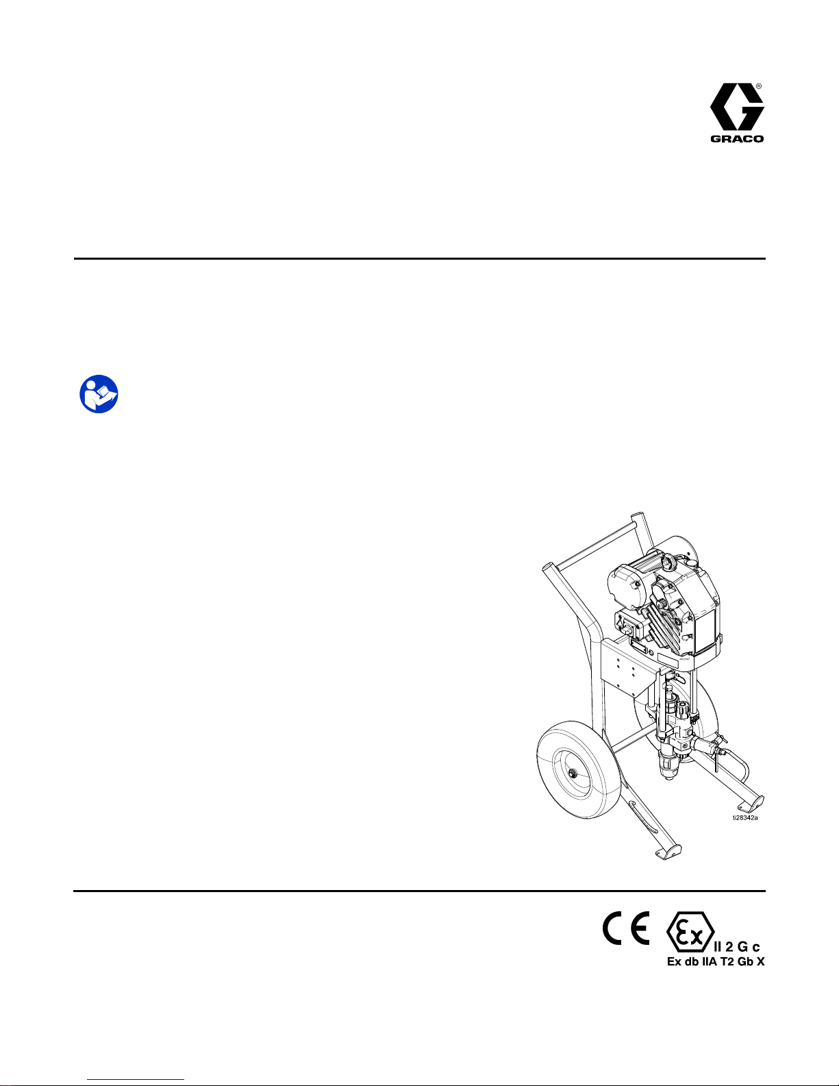
Operation,Repair,andParts
e e
e
- --Xtreme® Xtreme®
Xtreme®
Sprayer Sprayer
Sprayer
3A3164D
EN
Electric Electric
Electric
high high
high
pressure pressure
pressure
sprayer sprayer
sprayer
packages packages
packages
for for
for
application application
application
of of
of
protective protective
protective
coatings. coatings.
coatings.
For For
For
professional professional
professional
use use
use
only. only.
only.
Important Important
Important
Safety Safety
Safety
Instructions Instructions
Instructions
Readallwarningsandinstructionsinthismanualandinthee-Xtreme
Drivermanuals.Save Save
Save
all all
all
instructions. instructions.
instructions.
See page 3 for model information. See
Technical Specications for maximum
working pressure.
II 2 G c
Ex db IIA T2 Gb X
PROVENQUALITY.LEADINGTECHNOLOGY.
Page 2
Contents Contents
Contents
RelatedManuals................................................2
ModelInformation...............................................3
Warnings...........................................................4
ComponentIdentication.....................................7
Installation..........................................................8
PowerSupplyRequirements.........................8
ConnectthePowerSupply...........................8
Grounding...................................................8
InstallVentedOilCapBeforeUsing
Equipment......................................9
FlushBeforeUsingEquipment......................9
Setup.................................................................10
PressureReliefProcedure............................12
TriggerLock................................................12
Prime/Flush.................................................13
Spray.................................................................15
Shutdown...........................................................16
Maintenance......................................................16
PreventiveMaintenanceSchedule................16
ChangetheOil.............................................16
DailyMaintenance.......................................16
CheckOilLevel...........................................17
CorrosionProtection....................................17
Flushing......................................................17
CartMaintenance.........................................17
Troubleshooting..................................................18
ErrorCodeTroubleshooting..........................20
StandbyMode.............................................20
ErrorCodesTable........................................20
Repair................................................................22
XtremeLowerRemoval................................22
DisconnectandReconnectLower.................22
OutletCheckValves.....................................23
Parts..................................................................24
PartsDrawing..............................................24
OutletCheckValvesParts............................27
Dimensions........................................................29
TechnicalSpecications......................................32
GracoStandardWarranty....................................34
Related Related
Related
Manuals Manuals
Manuals
Part Part
Part
Description Description
Description
3A3165e-XtremeDriverInstallation
3A5124
e-XtremeDriverOperation,RepairandParts
311619PumpMountingKitManual
311762XtremeLowerManual
312145
XTRGunManual
2
3A3164D
Page 3
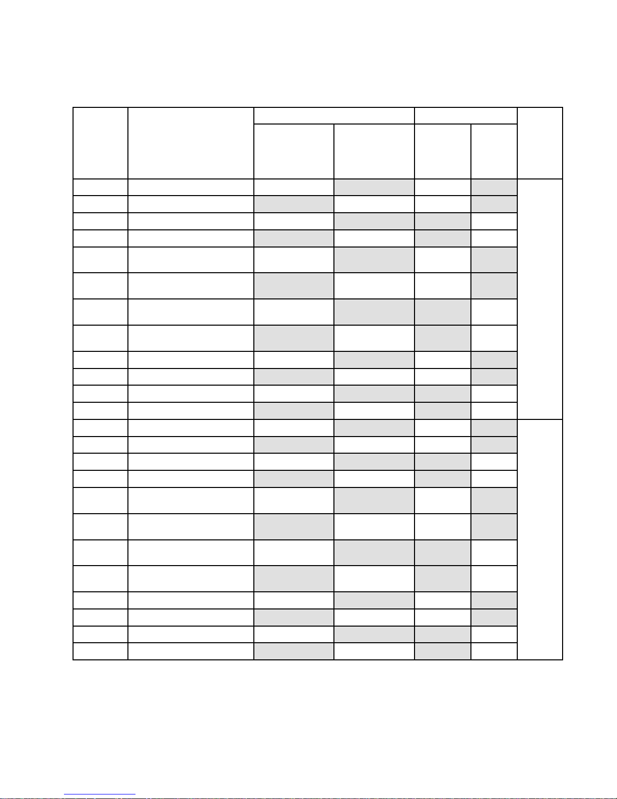
ModelInformation
Model Model
Model
Information Information
Information
Package Package
Package
Filter Filter
Filter
Model Model
Model
Description Description
Description
Complete* Complete*
Complete*
(Hose (Hose
(Hose
and and
and
Gun) Gun)
Gun)
MaximumFluid
Tempterature:
160°F(71°C)
Bare Bare
Bare
(No (No
(No
Hose Hose
Hose
or ororGun) Gun)
Gun)
MaximumFluid
Temperature:
180°F(82°C)
Integrated Integrated
Integrated
Filter Filter
Filter
No No
No
Filter Filter
Filter
Lower Lower
Lower
Pump Pump
Pump
24Y901*e-XtremeEx45,Cart*
✔✔
24Y902
e-XtremeEx45,Cart
✔✔
24Y903*e-XtremeEx45,Cart
✔✔
24Y904
e-XtremeEx45,Cart
✔✔
24Y905*e-XtremeEx45,Cart
withHopper
✔✔
24Y906
e-XtremeEx45,Cart
withHopper
✔✔
24Y907*e-XtremeEx45,Cart
withHopper
✔✔
24Y908
e-XtremeEx45,Cart
withHopper
✔✔
24Y909*
e-XtremeEx45,WallMount
✔✔
24Y910e-XtremeEx45,WallMount
✔✔
24Y911*
e-XtremeEx45,WallMount
✔✔
24Y912e-XtremeEx45,WallMount
✔✔
145cc
24Z901*e-XtremeEx35,Cart
✔✔
24Z902
e-XtremeEx35,Cart
✔✔
24Z903*e-XtremeEx35,Cart
✔✔
24Z904
e-XtremeEx35,Cart
✔✔
24Z905*e-XtremeEx35,Cart
withHopper
✔✔
24Z906
e-XtremeEx35,Cart
withHopper
✔✔
24Z907*e-XtremeEx35,Cart
withHopper
✔✔
24Z908
e-XtremeEx35,Cart
withHopper
✔✔
24Z909*
e-XtremeEx35,WallMount
✔✔
24Z910e-XtremeEx35,WallMount
✔✔
24Z911*
e-XtremeEx35,WallMount
✔✔
24Z912e-XtremeEx35,WallMount
✔✔
180cc
Formaximumworkingpressure,seeTechnicalSpecications,page32.
*LowerFluidtemperatureduetoXTR5gun.
NOTE: NOTE:
NOTE:
Seethee-XtremeDriverInstallationmanualfordriverapprovalsinformation.
3A3164D 3
Page 4
Warnings
Warnings Warnings
Warnings
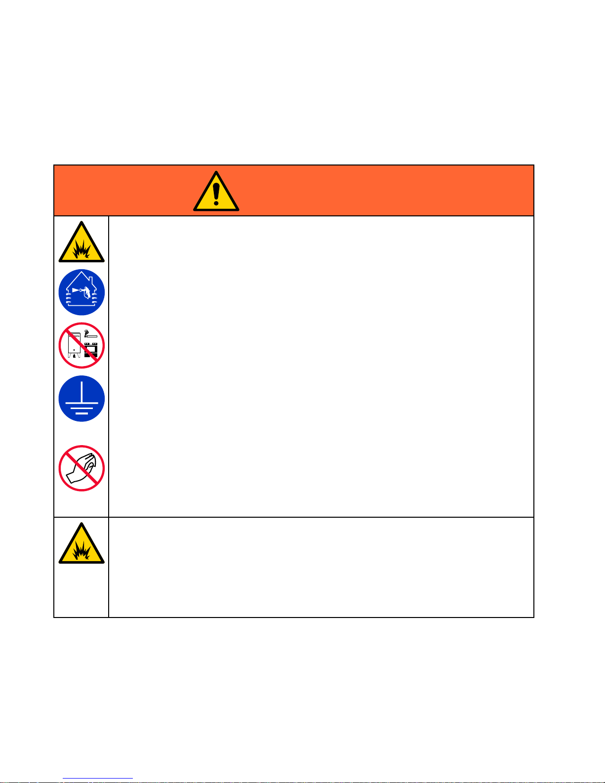
Thefollowingwarningsareforthesetup,use,grounding,maintenance,andrepairofthisequipment.The
exclamationpointsymbolalertsyoutoageneralwarningandthehazardsymbolsrefertoprocedure-specic
risks.Whenthesesymbolsappearinthebodyofthismanualoronwarninglabels,referbacktothese
Warnings.Product-specichazardsymbolsandwarningsnotcoveredinthissectionmayappearthroughout
thebodyofthismanualwhereapplicable.
WARNING WARNING
WARNING
FIRE FIRE
FIRE
AND AND
AND
EXPLOSION EXPLOSION
EXPLOSION
HAZARD HAZARD
HAZARD
Flammablefumes,suchassolventandpaintfumes,inwork work
work
area area
area
canigniteorexplode.Paint
orsolventowingthroughtheequipmentcancausestaticsparking.Tohelppreventreand
explosion:
•Useequipmentonlyinwellventilatedarea.
•Eliminateallignitionsources;suchaspilotlights,cigarettes,portableelectriclamps,and
plasticdropcloths(potentialstaticsparking).
•Groundallequipmentintheworkarea.SeeGrounding Grounding
Grounding
instructions.
•Neversprayorushsolventathighpressure.
•Keepworkareafreeofdebris,includingsolvent,ragsandgasoline.
•Donotplugorunplugpowercords,orturnpowerorlightswitchesonoroffwhenammable
fumesarepresent.
•Useonlygroundedhoses.
•Holdgunrmlytosideofgroundedpailwhentriggeringintopail.Donotusepaillinersunless
theyareantistaticorconductive.
•Stop Stop
Stop
operation operation
operation
immediately immediately
immediately
ifstaticsparkingoccursoryoufeelashock. ..Donotuse
equipmentuntilyouidentifyandcorrecttheproblem.
•Keepaworkingreextinguisherintheworkarea.
Staticchargemaybuilduponplasticpartsduringcleaningandcoulddischargeandignite
ammablevapors.Tohelppreventreandexplosion.
•Cleanplasticpartsonlyinwellventilatedareas.
•Donotcleanwithadrycloth.
•Donotoperateelectrostaticgunsinequipmentworkarea.
SPECIAL SPECIAL
SPECIAL
CONDITIONS CONDITIONS
CONDITIONS
FOR FOR
FOR
SAFE SAFE
SAFE
USE USE
USE
•Topreventtheriskofelectrostaticsparking,theequipment’snon-metallicpartsshouldbe
cleanedonlywithadampcloth.
•Thealuminumhousingmaysparkuponimpactorcontactwithmovingparts,whichmay
causereorexplosion.Takeprecautionstoavoidsuchimpactorcontact.
•Allameproofjointsarecriticaltotheintegrityofthedriverasapprovedforhazardous
locationsandarenotrepairableifdamaged.Damagedpartsmustbereplacedonlywith
genuineGracopartswithnosubstitutions.
4
3A3164D
Page 5
Warnings
WARNING WARNING
WARNING
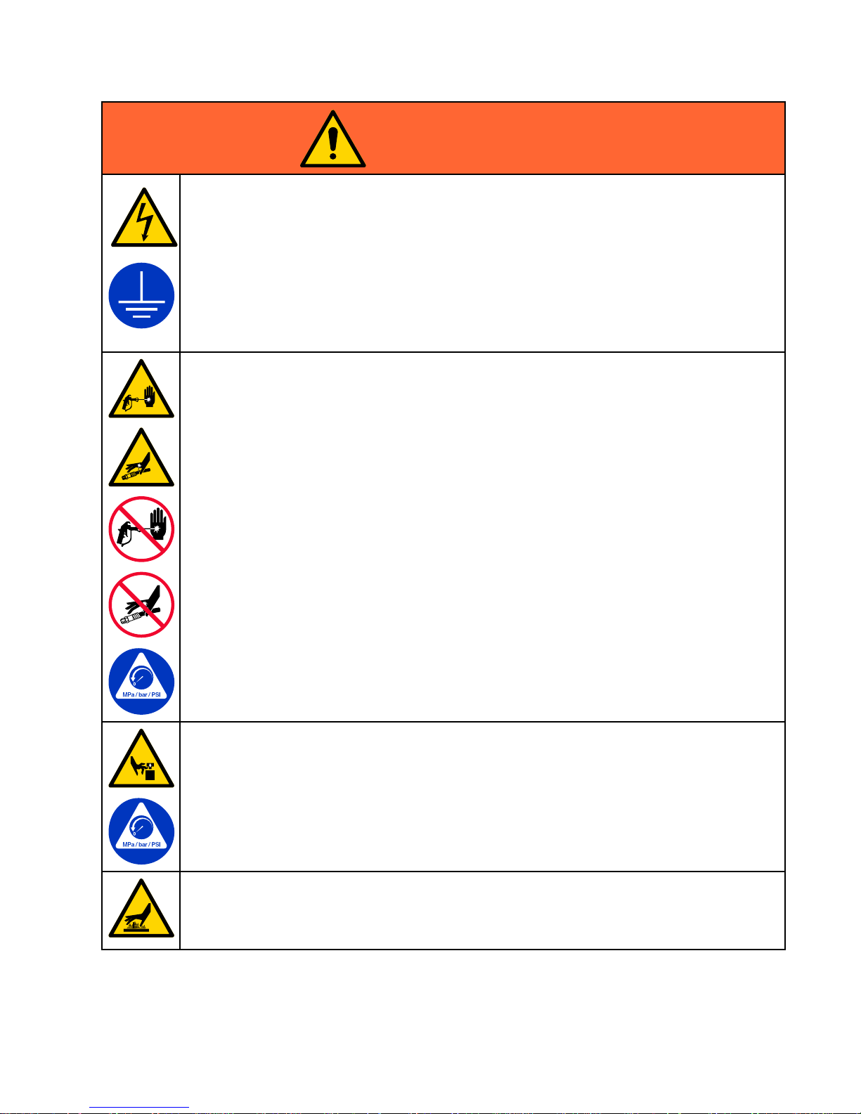
ELECTRIC ELECTRIC
ELECTRIC
SHOCK SHOCK
SHOCK
HAZARD HAZARD
HAZARD
Thisequipmentmustbegrounded.Impropergrounding,setup,orusageofthesystemcan
causeelectricshock.
•Turnoffanddisconnectpoweratmainswitchbeforedisconnectinganycablesandbefore
servicingorinstallingequipment.
•Connectonlytogroundedpowersource.
•Allelectricalwiringmustbedonebyaqualiedelectricianandcomplywithalllocalcodes
andregulations.
•Donotexposetorain.Storeindoors.
•Waitveminutesbeforeservicingafterpowerisremoved.
SKIN SKIN
SKIN
INJECTION INJECTION
INJECTION
HAZARD HAZARD
HAZARD
High-pressureuidfromgun,hoseleaks,orrupturedcomponentswillpierceskin.Thismay
looklikejustacut,butitisaseriousinjurythatcanresultinamputation.Get Get
Get
immediate immediate
immediate
surgical surgical
surgical
treatment. treatment.
treatment.
•Donotspraywithouttipguardandtriggerguardinstalled.
•Engagetriggerlockwhennotspraying.
•Donotpointgunatanyoneoratanypartofthebody.
•Donotputyourhandoverthespraytip.
•Donotstopordeectleakswithyourhand,body,glove,orrag.
•FollowthePressure Pressure
Pressure
Relief Relief
Relief
Procedure Procedure
Procedure
whenyoustopsprayingandbeforecleaning,checking,
orservicingequipment.
•Tightenalluidconnectionsbeforeoperatingtheequipment.
•Checkhosesandcouplingsdaily.Replacewornordamagedpartsimmediately.
MOVING MOVING
MOVING
PARTS PARTS
PARTS
HAZARD HAZARD
HAZARD
Movingpartscanpinch,cutoramputatengersandotherbodyparts.
•Keepclearofmovingparts.
•Donotoperateequipmentwithprotectiveguardsorcoversremoved.
•Pressurizedequipmentcanstartwithoutwarning.Beforechecking,moving,orservicing
equipment,followthePressure Pressure
Pressure
Relief Relief
Relief
Procedure Procedure
Procedure
anddisconnectallpowersources.
BURN BURN
BURN
HAZARD HAZARD
HAZARD
Equipmentsurfacesanduidthatisheatedcanbecomeveryhotduringoperation.Toavoid
severeburns:
•Donottouchhotuidorequipment.
3A3164D 5
Page 6
Warnings
WARNING WARNING
WARNING
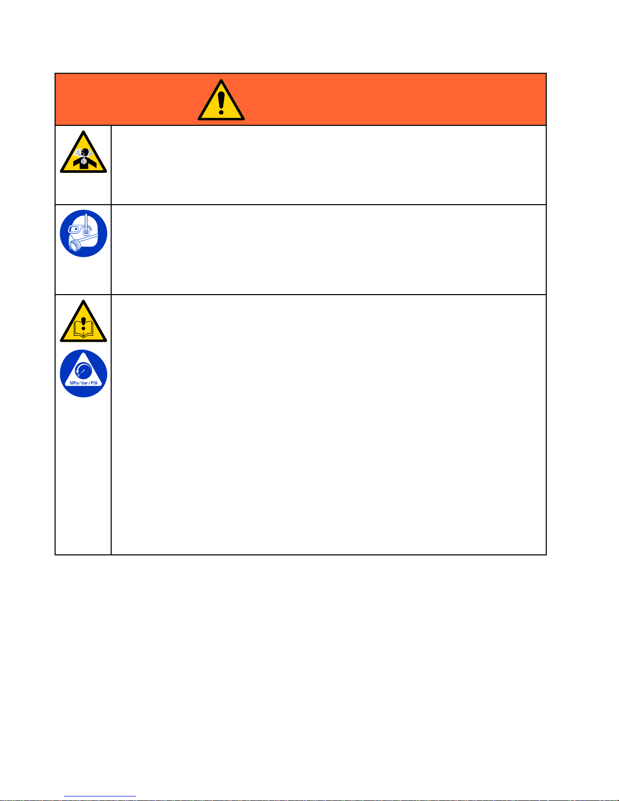
TOXIC TOXIC
TOXIC
FLUID FLUID
FLUID
OR OR
OR
FUMES FUMES
FUMES
Toxicuidsorfumescancauseseriousinjuryordeathifsplashedintheeyesoronskin,
inhaled,orswallowed.
•ReadSafetyDataSheets(SDSs)toknowthespecichazardsoftheuidsyouareusing.
•Storehazardousuidinapprovedcontainers,anddisposeofitaccordingtoapplicable
guidelines.
PERSONAL PERSONAL
PERSONAL
PROTECTIVE PROTECTIVE
PROTECTIVE
EQUIPMENT EQUIPMENT
EQUIPMENT
Wearappropriateprotectiveequipmentwhenintheworkareatohelppreventseriousinjury,
includingeyeinjury,hearingloss,inhalationoftoxicfumes,andburns.Thisequipmentincludes
butisnotlimitedto:
•Protectiveeyewear,andhearingprotection.
•Respirators,protectiveclothing,andglovesasrecommendedbytheuidandsolvent
manufacturer.
EQUIPMENT EQUIPMENT
EQUIPMENT
MISUSE MISUSE
MISUSE
HAZARD HAZARD
HAZARD
Misusecancausedeathorseriousinjury.
•Donotoperatetheunitwhenfatiguedorundertheinuenceofdrugsoralcohol.
•Donotexceedthemaximumworkingpressureortemperatureratingofthelowestrated
systemcomponent.SeeTechnical Technical
Technical
Data Data
Data
inallequipmentmanuals.
•Useuidsandsolventsthatarecompatiblewithequipmentwettedparts.SeeTechnical Technical
Technical
Data Data
Data
inallequipmentmanuals.Readuidandsolventmanufacturer’swarnings.Forcomplete
informationaboutyourmaterial,requestSafetyDataSheets(SDSs)fromdistributoror
retailer.
•Donotleavetheworkareawhileequipmentisenergizedorunderpressure.
•TurnoffallequipmentandfollowthePressure Pressure
Pressure
Relief Relief
Relief
Procedure Procedure
Procedure
whenequipmentisnotinuse.
•Checkequipmentdaily.Repairorreplacewornordamagedpartsimmediatelywithgenuine
manufacturer’sreplacementpartsonly.
•Donotalterormodifyequipment.Alterationsormodicationsmayvoidagencyapprovals
andcreatesafetyhazards.
•Makesureallequipmentisratedandapprovedfortheenvironmentinwhichyouareusingit.
•Useequipmentonlyforitsintendedpurpose.Callyourdistributorforinformation.
•Routehosesandcablesawayfromtrafcareas,sharpedges,movingparts,andhotsurfaces.
•Donotkinkoroverbendhosesorusehosestopullequipment.
•Keepchildrenandanimalsawayfromworkarea.
•Complywithallapplicablesafetyregulations.
6 3A3164D
Page 7
ComponentIdentication
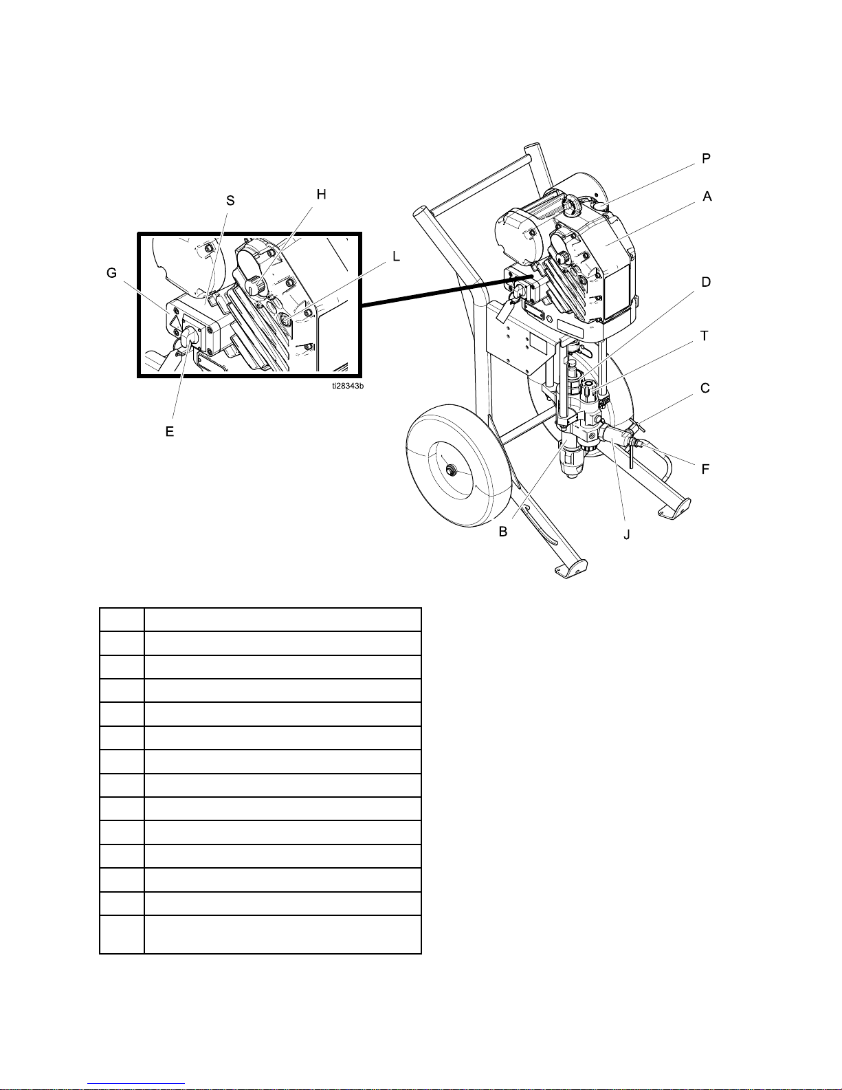
Component Component
Component
Identication Identication
Identication
Ref. Ref.
Ref.
Description Description
Description
AElectricDriver
BPumpLower
C
FluidDrain/PurgeValve
DPackingNut
E
PowerSwitch
F
FluidOutlet
GJunctionBoxCover
HPressureAdjustmentKnob
J
OutletCheckValve
L
StatusIndicatorLight(LED)
P
OilFillCap(vented)
S
JunctionBox
T
FilterCap(modelsequippedwithintegrated
lteronly)
NOTE: NOTE:
NOTE:
Seethee-XtremeDriverOperation/Repair
manualforwarninglabelinformation.
3A3164D
7
Page 8
Installation
Installation Installation
Installation
Toreducetheriskofelectricshock,reand
explosion,allelectricalwiringmustbedonebya
qualiedelectricianandcomplywithalllocalcodes
andregulations.
Power Power
Power
Supply Supply
Supply
Requirements Requirements
Requirements
SeeDriverInstallationmanualforinstructionsfor
powersupplyrequirements.
Connect Connect
Connect
the the
the
Power Power
Power
Supply Supply
Supply
SeeDriverInstallationmanualforinstructionsto
connectthepowersupply.
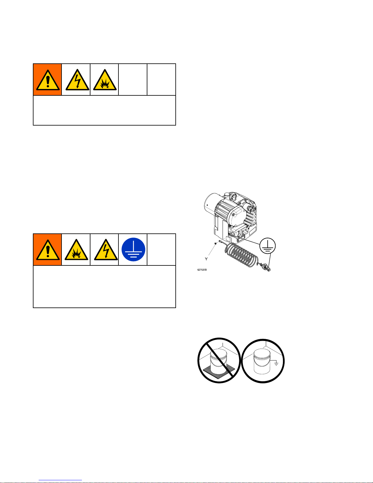
Grounding Grounding
Grounding
Thisequipmentmustbegroundedtoreducethe
riskofstaticsparkingandelectricshock.Electric
orstaticsparkingcancausefumestoigniteor
explode.Impropergroundingcancauseelectric
shock.Groundingprovidesanescapewireforthe
electriccurrent.
Sprayer: Sprayer:
Sprayer:
Systemisgroundedthroughthepower
cord.
Fluid Fluid
Fluid
hoses: hoses:
hoses:
Useonlyelectricallyconductivehoses
withamaximumof210ft.(64m)combinedhose
lengthtoensuregroundingcontinuity.Check
electricalresistanceofhoses.Iftotalresistance
togroundexceeds25megaohms,replacehose
immediately.
Spray Spray
Spray
gun: gun:
gun:
Groundthroughconnectiontoaproperly
groundeduidhoseandpump.
Fluid Fluid
Fluid
supply supply
supply
container: container:
container:
Followlocalcode.
Object Object
Object
being being
being
sprayed: sprayed:
sprayed:
Followlocalcode.
Solvent Solvent
Solvent
pails pails
pails
used used
used
when when
when
ushing: ushing:
ushing:
Followlocal
code.Useonlyconductivemetalpails,placedon
agroundedsurface.Donotplacethepailona
non-conductivesurface,suchaspaperorcardboard,
whichinterruptsgroundingcontinuity.
To To
To
maintain maintain
maintain
grounding grounding
grounding
continuity continuity
continuity
when when
when
ushing ushing
ushing
or or
or
relieving relieving
relieving
pressure: pressure:
pressure:
Holdthemetalpartofthespray
gun/dispensevalvermlytothesideofagrounded
metalpail,thentriggerthegun/valve.
Tools Tools
Tools
Required: Required:
Required:
•Groundingwiresandclampsforpails(Gracopart
244524–notsupplied)
•Two5gallon(19liter)metalpails(Gracopart
101108–notsupplied)
1.Connectthegroundwire(Y)toagroundstudon
thebackofthemotor.
2.Groundtheobjectbeingsprayed,uidsupply
container,andallotherequipmentinthe
workarea.Followyourlocalcode.Useonly
electricallyconductiveairanduidhoses.
3.Groundallsolventpails.Useonlymetalpails,
whichareconductive,placedonagrounded
surface.Donotplacepailonanon-conductive
surface,suchaspaperorcardboard,which
interruptsgroundingcontinuity.
8 3A3164D
Page 9
Installation
Install Install
Install
Vented Vented
Vented
Oil Oil
Oil
Cap Cap
Cap
Before Before
Before
Using Using
Using
Equipment Equipment
Equipment
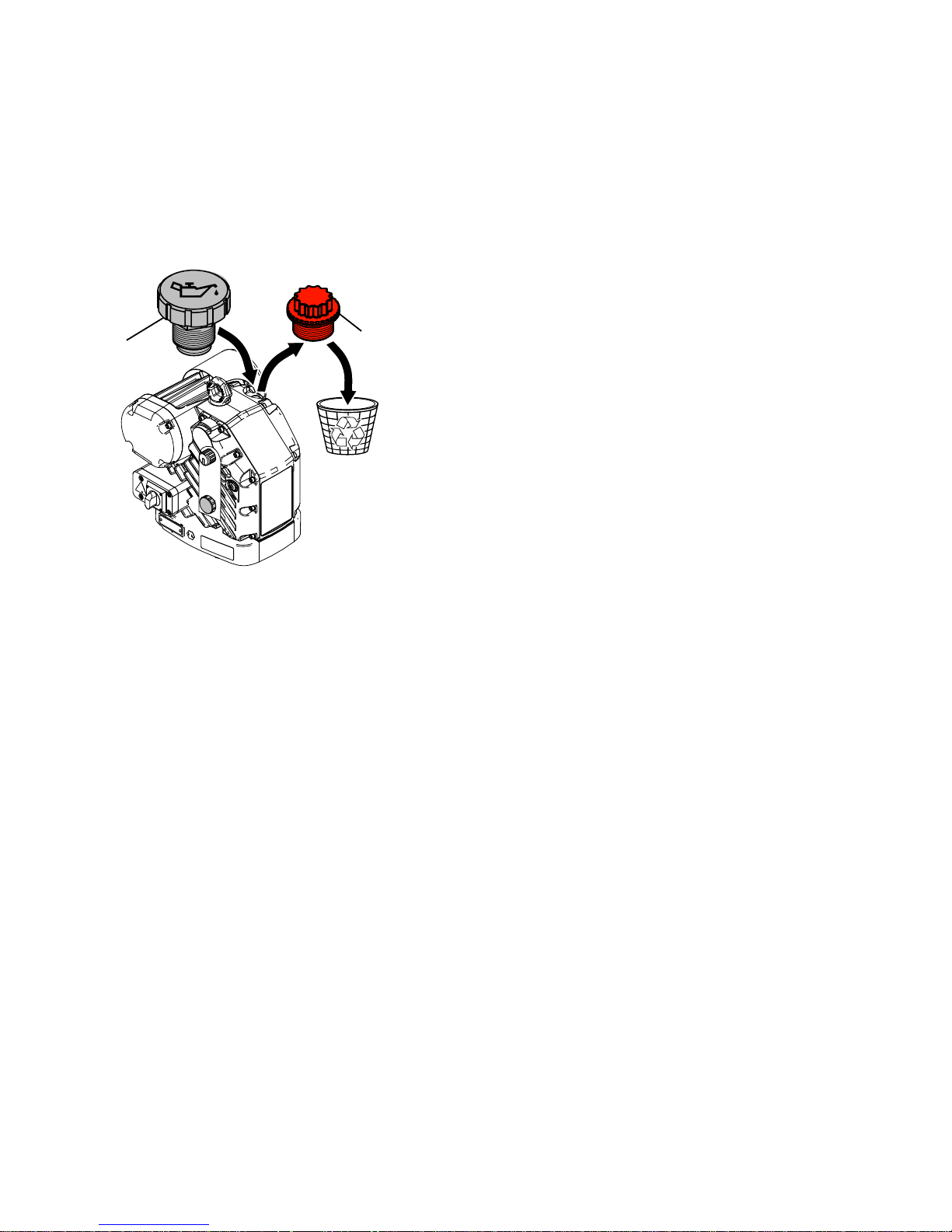
Thedrivergearboxisshippedfromthefactory
pre-lledwithoil.Thetemporaryunventedcap(PX)
preventsoilleaksduringshipment.Thistemporary
capmustbereplacedwiththesuppliedventedoil
cap(P)beforeuse.
PX
P
ti31010a
Flush Flush
Flush
Before Before
Before
Using Using
Using
Equipment Equipment
Equipment
Thepumpuidsectionwastestedwithlightweight
oil,whichisleftintheuidpassagestoprotectparts.
Toavoidcontaminatingyouruidwithoil,ushthe
equipmentwithacompatiblesolventbeforeusing
theequipment.
SeePrime/Flush,page13.
3A3164D 9
Page 10
Setup
Setup Setup
Setup
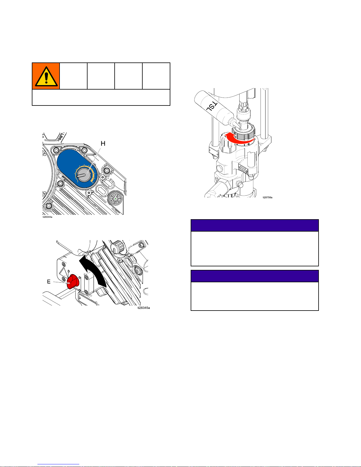
Toavoidtipover,makesurecartisonaatand
levelsurface.Failuretodosocouldresultininjury.
1.Pullpressureadjustmentknob(H)outandturn
counterclockwiseuntilitstops.Pushtheknob
intolock.
2.Turnpowerswitch(E)OFF.Connectunitto
powersource.
OFF
3.Checkpackingnut(D).SeeXtremelowerpump
manual311762forpackingnuttorque.Fillwith
ThroatSealLiquid(TSL
TM
).
4.Attachelectricallyconductiveuidhosetopump
loweroutletviaoutletcheckvalveandtighten.
NOTICE NOTICE
NOTICE
Attachingthehosedirectlytothelowerpump
canresultindamagetothesprayerduring
cavitation,orwhenthesprayerrunsoutof
material.Useanoutletcheckvalvebetween
thelowerpumpandhosetoavoiddamage.
NOTICE NOTICE
NOTICE
Theminimumhosesizeallowableis3/8in.
IDx50ft(10mmx15m).Smallerhoses
cancausehighpressurespikesandresultin
damagetothesprayer.
5.Attachhosetogunandtighten.
10 3A3164D
Page 11
Setup
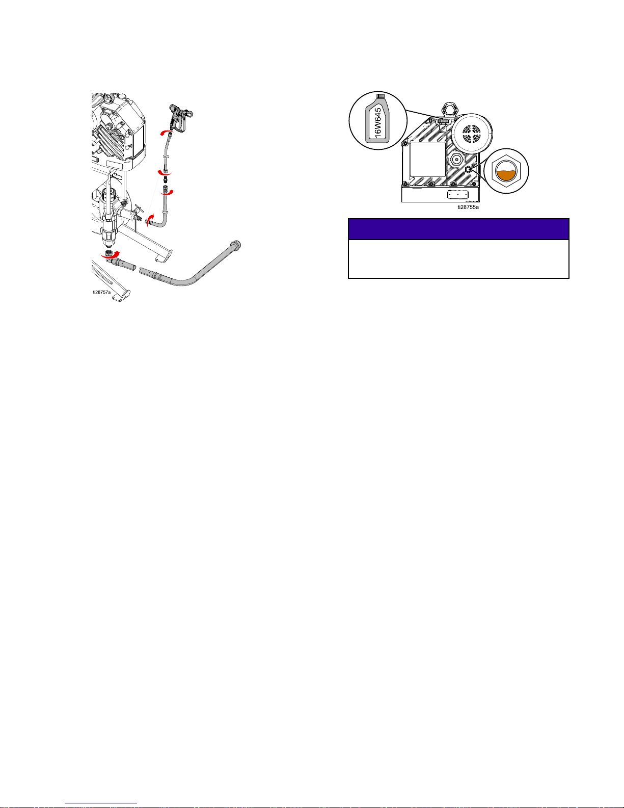
6.Attachmaterialsupplyinlethosetopumplower.
NOTE: NOTE:
NOTE:
Maximumsuggestedlengthis6ft(1.8
m),minimumsuggestedinnerdiameteris1in.
(2.5cm).
7.Checkoillevel.
NOTICE NOTICE
NOTICE
OnlyuseoilwithGracopartnumber16W645.
Anyotheroilmaynotlubricateproperlyand
cancausedamagetothedrivetrain.
8.Alwaysushandprimesprayerbeforeeachuse
(seePrime/Flush,page13).
3A3164D
11
Page 12
Setup
Pressure Pressure
Pressure
Relief Relief
Relief
Procedure Procedure
Procedure
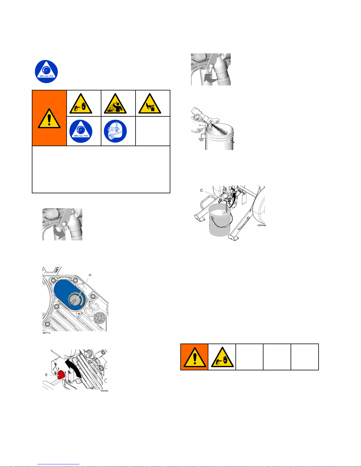
FollowthePressureReliefProcedure
wheneveryouseethissymbol.
Thisequipmentstayspressurizeduntilpressure
ismanuallyrelieved.Tohelppreventserious
injuryfrompressurizeduid,suchasskininjection,
splashinguidandmovingparts,followthe
PressureReliefProcedurewhenyoustopspraying
andbeforecleaning,checking,orservicingthe
equipment.
1.Engageguntriggerlock.
2.Pullpressureadjustmentknob(H)outandturn
counterclockwiseuntilitstops.Pushtheknob
intolock.
3.Turnpowerswitch(E)OFF.
OFF
4.Disengageguntriggerlock.
5.Holdgunrmlyagainstagroundedmetalpail.
Triggerthegun.
6.Engageguntriggerlock.
7.Drain Drain
Drain
uid: uid:
uid:
Placethedraintubeinagrounded
wastepail.Slowlyopenuiddrain/purgevalve
(C),anddrainuidintoawastepail.
8.Ifyoususpectthespraytiporhoseiscompletely
cloggedorthatpressurehasnotbeenfully
relieved:
a.VERYSLOWLYloosenthetipguard
retainingnutorhoseendcouplingtorelieve
pressuregradually.
b.Loosenthenutorhoseendcoupling
completely.
c.Withtipremoved,triggerthegunintothe
bucket.
Trigger Trigger
Trigger
Lock Lock
Lock
Alwaysengagethetriggerlockwhenyoustop
sprayingtopreventthegunfrombeingtriggered
accidentallybyhandorifdroppedorbumped.
12
3A3164D
Page 13
Setup
Prime/Flush Prime/Flush
Prime/Flush
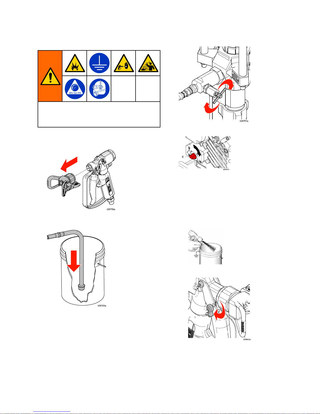
Toavoidreandexplosion,alwaysground
equipmentandwastecontainer.Toavoidstatic
sparkingandinjuryfromsplashing,alwaysushat
thelowestpossiblepressure.
1.PerformPressureReliefProcedure,page12.
2.Removetipandtipguardfromgun.
3.Placematerialsupplysuctionhoseinto
compatibleuid(ifpriming)orsolvent(ifushing).
4.Closedrainvalve.
5.Turnpowerswitch(E)ON.
ON
6.Primeorushhoseandgun:
a.Disengageguntriggerlock.
b.Triggergunintogroundedpail.Pullout
pressureadjustmentknob(H)andturn
clockwiseslowlytoincreasepressure,until
asteadystreamowsfromgun.Pushknob
intolock.Ifushing ushing
ushing
,triggergununtilclean
solventowsfromthegun.
c.Engagetriggerlock.
3A3164D 13
Page 14
Setup
7.Ifpriming,equipmentisnowreadytospray
(proceedtoSpray,page15).Ifushing,proceed
withstep8.
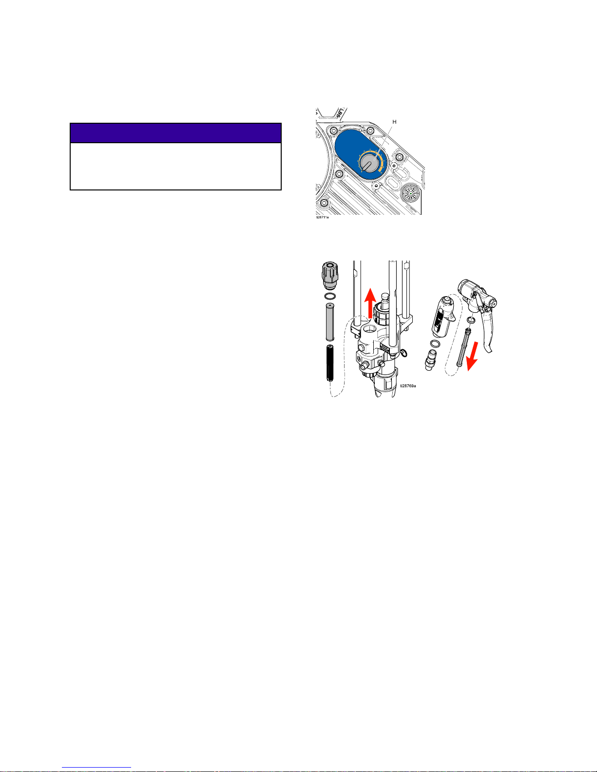
NOTE: NOTE:
NOTE:
Theremainingstepsareforushingonly.
NOTICE NOTICE
NOTICE
Donotprimepumpthroughdrain/purge
valveusingtwocomponentmaterials.Mixed
two-componentmaterialswillhardeninvalve
andresultinclogging.
8.PerformPressureReliefProcedure,page12.
9.Turnpowerswitch(E)ON.
10.Tostartpump,pulloutpressureadjustment
knob(H)andturnclockwiseslowlytoincrease
pressure,untilasteadystreamowsfromdrain
valve.Pushknobintolock.
NOTE: NOTE:
NOTE:
Todeterminetheproperamountof
solventandushingtime,removetheinlet
valvehousingtoverifyithasbeenfullycleaned,
especiallywhensprayinganewmaterialforthe
rsttime.
11.Waitforcleansolventtoowfromdraintube.
12.Pullpressureadjustmentknob(H)outandturn
counterclockwiseuntilitstops.Pushtheknob
intolock.
13.Turnthepowerswitch(E)OFF.
14.Checkpumpandgunlters.
14
3A3164D
Page 15
Spray
Spray Spray
Spray
NOTICE NOTICE
NOTICE
Donotallowpumptorundry.Itwillquickly
acceleratetoahighspeedcausingdamage.
1.PerformPrime/Flush,page13.
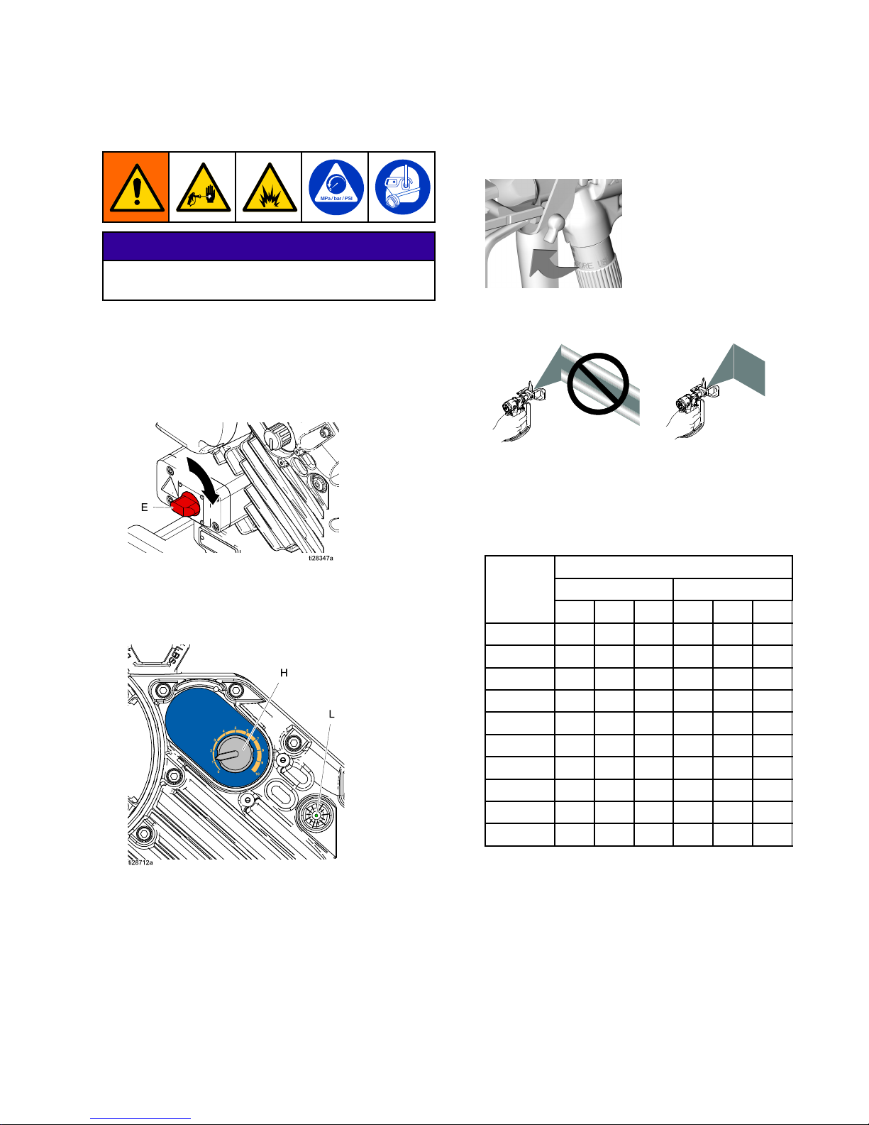
2.PerformPressureReliefProcedure,page12.
3.Installtipandtipguardontogun.Closethedrain
valve.
4.Turnpowerswitch(E)ON.
ON
5.Pulloutandturnpressureadjustmentknob
(H)untildesiredpressureisreached.Turn
clockwisetoincreasepressure,counterclockwise
todecreasepressure.Pushknobintolock.
6.Disengageguntriggerlock.
7.Sprayatestpattern.Readuidmanufacturer’s
recommendations.Adjustasnecessary.
NOTE: NOTE:
NOTE:
Whendeterminingthedesiredspray
pressure,alwaysincreasethespraypressure
untilthespraypatternfullydevelops.Thiswill
reducethepressuresurgewhenthepumpis
stalledandminimizeover-spray.
Dynamic Dynamic
Dynamic
Pump Pump
Pump
Outlet Outlet
Outlet
Pressure Pressure
Pressure
Ex35 Ex35
Ex35
Ex45 Ex45
Ex45
Pressure Pressure
Pressure
Adjust- Adjust-
Adjust-
ment ment
ment
Knob Knob
Knob
Setting Setting
Setting
PSI PSI
PSI
Bar Bar
Bar
MPa MPa
MPa
PSI PSI
PSI
Bar Bar
Bar
MPA MPA
MPA
132022.02.2040027.02.70
264044.04.4080054.05.40
396066.06.60120081.08.10
4128088.08.80160010810.8
5
160011011.0200013513.5
6192013213.2240016216.2
7
224015415.4280018918.9
8256017617.6320021621.6
9288019819.8360024324.3
10320022022.0400027027.0
8.Flushwhennishedspraying.
PerformPrime/Flush,page13and
PressureReliefProcedure,page12.
3A3164D 15
Page 16
Shutdown
Shutdown Shutdown
Shutdown
NOTICE NOTICE
NOTICE
Neverleavewaterorwater-baseduidinpump
overnight.Ifwater-baseuidhasbeenused,ush
withwaterrst,thenwitharustinhibitor(suchas
mineralspirits).Relievepressure,butleaverust
inhibitorinpumptoprotectpartsfromcorrosion.
Toshutdown:
1.PerformPrime/Flush,page13.
2.PerformPressureReliefProcedure,page12.
Maintenance Maintenance
Maintenance
NOTICE NOTICE
NOTICE
Donotopen/removegearcover.Thegearside
isnotintendedtobeserviced.Openingthegear
covermayalterthefactorysetbearingpre-load
andmayreducetheproductlife.
Preventive Preventive
Preventive
Maintenance Maintenance
Maintenance
Schedule Schedule
Schedule
Theoperatingconditionsofyourparticularsystem
determinehowoftenmaintenanceisrequired.
Establishapreventivemaintenancescheduleby
recordingwhenandwhatkindofmaintenanceis
needed,andthendeterminearegularschedulefor
checkingyoursystem.
Change Change
Change
the the
the
Oil Oil
Oil
NOTE: NOTE:
NOTE:
Changetheoilafterabreak-inperiodof
200,000–300,000cycles.Afterthebreak-inperiod,
changetheoilonceayear.
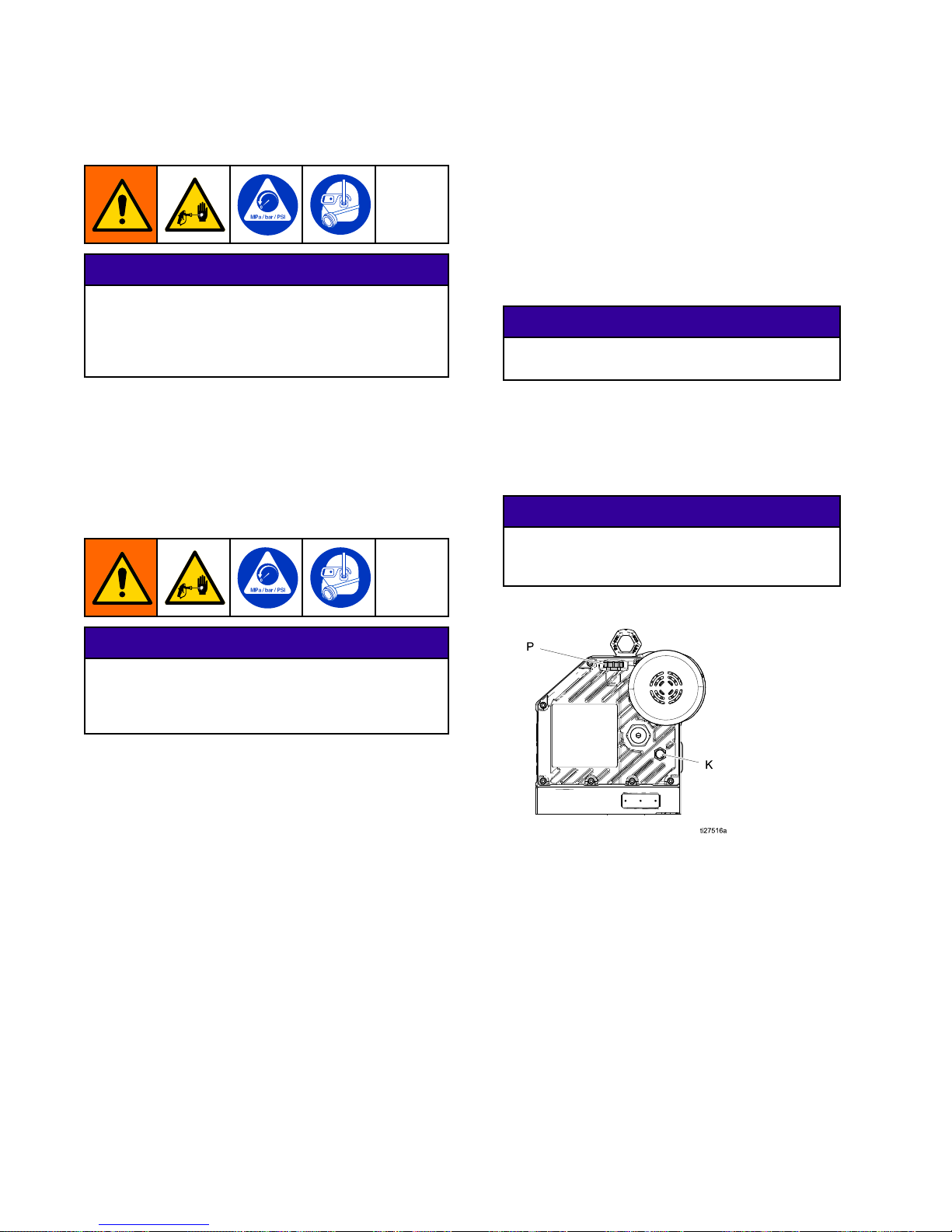
1.Placeaminimum2quart(1.9liter)container
undertheoildrainport.Removetheoildrain
plug.Allowalloiltodrainfromthedriver.
2.Reinstalltheoildrainplug.Torqueto18–23ft-lb
(25–30N•m).
NOTICE NOTICE
NOTICE
Donotover-torque.Thedrainplugcan
becomestrippedanddamaged.
3.Opentheoilllcap(P)andaddGracoPartNo.
16W645silicone-freeISO220syntheticEPgear
oil.Checktheoillevelinthesightglass(K).Fill
untiltheoillevelisnearthehalfwaypointofthe
sightglass.Theoilcapacityisapproximately
1.0–1.2quarts(0.9–1.1liters).Do Do
Do
not not
not
overll. overll.
overll.
NOTICE NOTICE
NOTICE
OnlyuseoilwithGracopartnumber16W645.
Anyotheroilmaynotlubricateproperlyand
cancausedamagetothedrivetrain.
4.Reinstalltheoilllcap(P).
Daily Daily
Daily
Maintenance Maintenance
Maintenance
NOTE: NOTE:
NOTE:
Forovernightshutdown,stoppumpatbottom
ofitsstroketopreventuidfromdryingonexposed
displacementrodanddamagingthroatpackings.
PerformPressureReliefProcedure,page12.
1.PerformPrime/Flush,page13.
2.PerformPressureReliefProcedure,page12.
3.Checkpackingnut(D).Adjustpackingsand
replaceTSLasnecessary.Seelowerpump
manual311762forpackingnuttoque.
4.Checkhoses,tubes,andcouplings.tightenall
uidconnectionsbeforeeachuse.
16 3A3164D
Page 17
Maintenance
Check Check
Check
Oil Oil
Oil
Level Level
Level
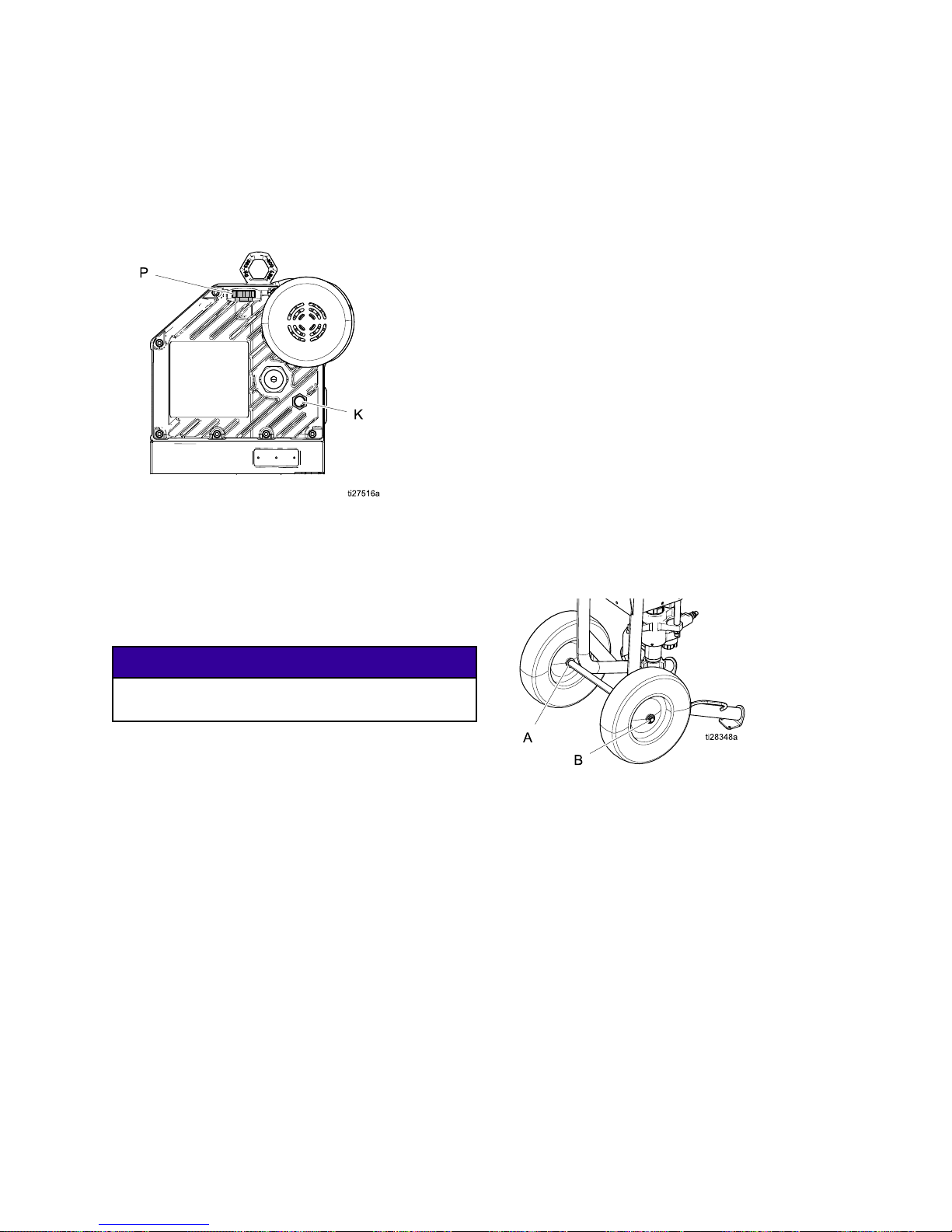
Checktheoillevelinthesightglass(K).Theoillevel
shouldbenearthehalfwaypointofthesightglass
whenthesprayerisnotrunning.Ifoilislow,open
thellcap(P)andaddGracoPartNo.16W645
silicone-freeISO220syntheticEPgearoil.
Theoilcapacityisapproximately1.0–1.2quarts
(0.9–1.1liters).Do Do
Do
not not
not
overll. overll.
overll.
NOTE: NOTE:
NOTE:
Thedrivergearboxisshippedfromthe
factorypre-lledwithoil.Thetemporaryunvented
cap(PX)preventsoilleaksduringshipment.This
temporarycapmustbereplacedwiththesupplied
ventedoilcap(P)beforeuse.
NOTICE NOTICE
NOTICE
OnlyuseoilwithGracopartnumber16W645.Any
otheroilmayreducethelifeofthegears.
Corrosion Corrosion
Corrosion
Protection Protection
Protection
Alwaysushthepumpbeforeuiddrieson
thedisplacementrod.Neverleavewateror
water-baseduidinthepumpovernight.First,
ushwithwateroracompatiblesolvent,thenwith
arustinhibitor,suchasmineralspirits.Perform
PressureReliefProcedure,page12,butleaverust
inhibitorinpumptoprotectpartsfromcorrosion.
Flushing Flushing
Flushing
•Flushbeforechanginguids,beforeuidcancure
intheequipment,attheendoftheday,before
storing,andbeforerepairingequipment.
•Flushatthelowestpressurepossible.Check
connectorsforleaksandtightenasnecessary.
•Flushwithauidthatiscompatiblewiththeuid
beingdispensedandtheequipmentwettedparts.
Cart Cart
Cart
Maintenance Maintenance
Maintenance
PeriodicallylubricatetheaxlebetweenpointsAand
Bwithlightweightoil(seebelow).
Keepthecartcleanbywipingupspillsdaily,usinga
compatiblesolvent.
3A3164D
17
Page 18
Troubleshooting
Troubleshooting Troubleshooting
Troubleshooting
NOTE: NOTE:
NOTE:
Checkallpossibleremediesbefore
disassemblingpump.
NOTE: NOTE:
NOTE:
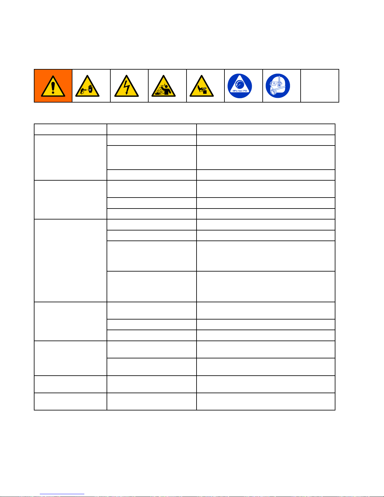
Thestatusindicator(L)onthedriverwillblink
ifanerrorisdetected.
Problem Problem
Problem
Cause Cause
Cause
Solution Solution
Solution
ExhausteduidsupplyRellandprimethepump.
Cloggeduidoutletline,gun*,
etc.;thehoseinnerdiameter
istoosmall
Clearthehose,outletcheckvalve,orgun;use
thehosewiththelargerinnerdiameter.
Pumpoutputlowon
bothstrokes
Wornpistonpacking
Replace.Seethepumplowermanual.
Improperlyinstalledintakeor
pistoncheckvalves
Checkandrepair.Seepumpthelowermanual.
Theintakevalveisclogged.
Cleantheintakevalve.
Nooutput
ExhausteduidsupplyRellandprimethepump.
ExhausteduidsupplyRellandprimethepump.
Cloggeduidhoseorgun*Cleanthehoseorgun.
Fluiddriedonthepistonrod
Disassembleandcleanthepump(seethelower
manual).Inthefuture,stopthepumpatthe
bottomofthestroke.Keepthewet-cuplled
withcompatiblesolvent.
Pumpwillnotoperate
Driverpartsarewornor
damaged
Repairorreplacethedriver.Removethelower
fromthedriver.Ifthedriverwillnotcycleand
doesnotblinkanerrorcode,thentroubleshoot
thedriverorreplace.
Fluidisleakingfromthe
rupturedisk
Replacetherupturedisk;donotreplacewitha
pipeplug.
Theintakevalveisclogged.
Cleantheintakevalve.
NoPressureorFlow
Leakingdrainvalve
Closeorreplacethedrainvalve.
Overvoltage(over300V)SeepowersupplyrequirementsintheDriver
Installationmanual.
Driverdoesnotturnon
Nopowertothecontrolboard.
Verifythatthepowersupplyisconnected.
checkthejunctionboxconnections.
Outputlowondown
stroke
OpenorwornintakevalveClearorservicetheintakevalve.
OutputlowonupstrokeOpenorwornpistonvalve
packings
Clearthepistonvalve.Replacethepackings.
18 3A3164D
Page 19
Troubleshooting
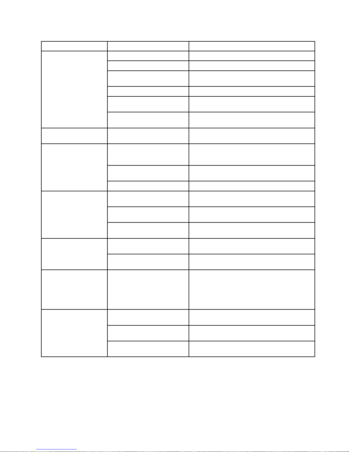
Problem Problem
Problem
Cause Cause
Cause
Solution Solution
Solution
Fluidsupplyisexhausted
Relltheuidsupplyandprimethepump.
CloggedsuctionCleanthesuctiontube.
Openorwornpistonvalve
packings
Clearthepistonvalve.Replacethepackings.
OpenorwornintakevalveClearorservicetheintakevalve.
Cloggedgun,hose,outlet,
etc.
Clearthegun,hose,outlet,etc.
Erraticoraccelerated
pumpspeed
Openorwornoutletcheck
valve
Clearorservicetheoutletcheckvalve.
Cyclesorfailstohold
pressureatstall
Wornintakeorpistonvalveor
seals
Servicethepumplower(seeLowermanual
311762).
LoosesuctionlineTightensuctionlineconnections.Use
compatibleliquidthreadsealantorPTFEtape
onconnections.
Agitator/mixerisnot
submerged
Submergetheagitator/mixer.
Airbubblesinuid
Agitator/mixerRPMistoohighLowertheagitator/mixerRPM.
IncorrectuidpressureatgunSeethegunmanual.Readtheuid
manufacturer’srecommendations.
Fluidistoothinortoothick
Adjusttheuidviscosity.Readtheuid
manufacturer’srecommendations.
Poornishorirregular
spraypattern
Dirty,worn,ordamagedspray
gun
Servicethespraygun(seespraygunmanual).
Overvoltage(greaterthan
300V)
Checkthepowersupply.
Driverdoesnotturn
overandLEDisoff
Nopowertothecontrolboard
ContactyourGracodistributororTechService
formoreinformation.
Driverdoesnotturn
overandLEDison
EncoderfaultCyclepower.
Recalibratetheencoderfollowingtheprocedure
listedinthee-XtremeDriverOperation/Repair
manual.
ContactyourGracodistributororTechService
formoreinformation.
Oilwasover-lledDrainandrelloilasstatedin
CheckOilLevel,page17.
Drainplugisnottightened
properly
Torqueto18–23ft-lb(25–30N•m).
Oilisleaking
Sealcartridgeo-ringmissing
ordamaged
Replacetheshaftbearingassembly.
*
To determine if the uid hose or gun is obstructed, follow the Pressure Relief Procedure , page 12 . Disconnect
uid hose and place a container at pump uid outlet to catch any uid. Turn pressure adjustment knob just
enough to start the pump. If the pump starts, the obstruction is in the uid hose or gun.
3A3164D 19
Page 20
Troubleshooting
Error Error
Error
Code Code
Code
Troubleshooting Troubleshooting
Troubleshooting
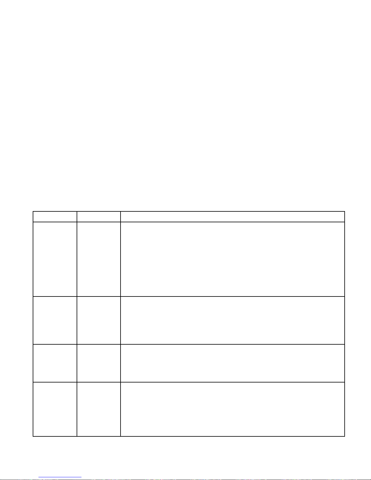
Errorcodescantaketwoforms:
•Alarm: Alarm:
Alarm:
Alertsyoutothecauseofthealarmand
shutsdownthedriver.
•Deviation: Deviation:
Deviation:
Alertsyoutotheproblem,butthedriver
maycontinuetorunpastthesetlimitsuntilthe
systemabsolutelimitsarereached.
NOTE: NOTE:
NOTE:
Theblinkcodeisdisplayedusingthestatus
indicator(L)onthedriver.Theblinkcodegivenbelow
indicatesthesequence.Forexample,blinkcode2
indicatestwoblinks,apause,andthenrepeats.
NOTE: NOTE:
NOTE:
Toclearanerrorcode,rsttryturningthe
pressureadjustmentknob(H)counterclockwiseuntil
itstops.Ifthestatusindicator(L)doesnotstop
blinkingshortlyafterturningtheknobtozero,cycle
thepowerbyturningthepowerswitch(E)totheOFF
positionforatleast30secondsbeforeturningback
ON.
Standby Standby
Standby
Mode Mode
Mode
Whenslowblinkingisdisplayed,thedriverhas
enteredStandbyMode.Thedriverwillenterstandby
modewhenpoweredonandpressurizedwithaknob
settinggreaterthan7,andthepumphasnotmoved
anymaterialfor30minutes.
StandbyModewillbeexitedwhen:
•Materialstartstodispenseandcausesthepump
tomove,OR
•Thepressurecontrolknob(H)isadjusted,OR
•Thepowerswitch(E)iscycledOFFandON
Error Error
Error
Codes Codes
Codes
Table Table
Table
Blink Blink
Blink
Code Code
Code
Error Error
Error
Type Type
Type
Troubleshooting Troubleshooting
Troubleshooting
Steps Steps
Steps
1AlarmPump Pump
Pump
diving diving
diving
Thepumpisdivingrapidly.Apressureimbalancebetweentheupanddown
strokeofthepumpiscausingthepumptodivewithexcessivespeed.
•Pumpdivingmayoccurwhenthepumprunsoutofmaterialwhilespraying
athighpressure.
•Verifythatmaterialisbeingproperlyfedtothepump.
•Pressurefromthehosecouldowbackintothepumponthedownstroke.
•Verifythatthecheckvalveisinstalledandisproperlyworking.
2AlarmVoltage Voltage
Voltage
Too Too
Too
Low Low
Low
•Verifythatlinevoltageiswithintherangespeciedin
TechnicalSpecications,page32.
•UsetherecommendedcordinPowerSupplyRequirements,page8.
•Cyclepowerandcheckstatusindicator(L)toseeiftheerrorisstillactive.
3AlarmVoltage Voltage
Voltage
Too Too
Too
High High
High
•Verifythatlinevoltageiswithintherangespeciedin
TechnicalSpecications,page32.
•Cyclepowerandcheckstatusindicator(L)toseeiftheerrorisstillactive.
4DeviationHigh High
High
Temperature Temperature
Temperature
Thetemperatureofthesystemisnearthemaximumoperationtemperature.The
performancehasbeenreducedtopreventthedriverfromcompletelyshutting
down.
•Reducepressure.
•Movetheunittoacoolerlocation.
20 3A3164D
Page 21
Troubleshooting
Blink Blink
Blink
Code Code
Code
Error Error
Error
Type Type
Type
Troubleshooting Troubleshooting
Troubleshooting
Steps Steps
Steps
5
DeviationLow Low
Low
Temperature Temperature
Temperature
•Warmequipment.
6AlarmMotor Motor
Motor
Temperature Temperature
Temperature
Fault Fault
Fault
Motorisrunningtoohot.Allowunittocool.
•Reducepressure.
•Movetheunittoacoolerlocation.
7
AlarmBoard Board
Board
Temperature Temperature
Temperature
Fault Fault
Fault
Thecontrolboardisrunningtoohot.Allowtheunittocool.
•Reducepressure.
•Movetheunittoacoolerlocation.
8Alarm
Encoder Encoder
Encoder
Calibration Calibration
Calibration
Error Error
Error
•Cyclepowerandcheckstatusindicator(L)toseeiftheerrorisstillactive.
•Followthecalibrationprocedurelistedinthee-XtremeDriverOperation/Repair
manualtocalibratetheencoder(thiscodewillblinkifcalibrationisinprogress).
•ContactyourGracodistributororTechServiceformoreinformation.
9AlarmEncoder Encoder
Encoder
Error Error
Error
•Cyclepowerandcheckthestatusindicator(L)toseeiftheerrorisstillactive.
•Verifythattheinternalconnectionsareintact.
•ContactyourGracodistributororTechServiceformoreinformation.
10Alarm
Software Software
Software
Versions Versions
Versions
Do Do
Do
Not Not
Not
Match Match
Match
•Obtainsoftwareupdatetoken.SeeAccessories Accessories
Accessories
sectionfortokenpartnumber.
SeetheDriverOperation/Repairmanualfortokeninstallationinformation.
11Alarm
Circuit Circuit
Circuit
Board Board
Board
Communication Communication
Communication
Failure Failure
Failure
•Cyclepowerandcheckstatusindicator(L)toseeiftheerrorisstillactive.
•ContactyourGracodistributororTechServiceformoreinformation.
12Alarm
Internal Internal
Internal
Circuit Circuit
Circuit
Board Board
Board
Hardware Hardware
Hardware
Failure Failure
Failure
•Cyclepowerandcheckstatusindicator(L)toseeiftheerrorisstillactive.
•ContactyourGracodistributororTechServiceformoreinformation.
13,14Alarm
Internal Internal
Internal
Software Software
Software
Error Error
Error
•Cyclepowerandcheckstatusindicator(L)toseeiftheerrorisstillactive.
•ContactyourGracodistributororTechServiceformoreinformation.
SlowBlink
Deviation
SeeStandbyMode,page20.
3A3164D
21
Page 22
Repair
Repair Repair
Repair
Toreducetheriskofinjuryduetoskin
injectionandsplashing,performthe
PressureReliefProcedure,page12before
performinganyrepairprocedure.
Xtreme Xtreme
Xtreme
Lower Lower
Lower
Removal Removal
Removal
Required Required
Required
Tools Tools
Tools
•Setofadjustablewrenches
•Torquewrenches
•Rubbermallet
•Threadlubricant
•Anti-seizelubricant
•Threadsealant
Disconnect Disconnect
Disconnect
and and
and
Reconnect Reconnect
Reconnect
Lower Lower
Lower
1.Flushthepump(seePrime/Flush,page13).
Stopthepumpatbottomofitsstroke.
2.PerformPressureReliefProcedure,page12.
3.Disconnecttheunitfromthepowersource.
4.Disconnecttheuidhose,thendisconnectthe
suctionhose.Holdtheuidinletttingwith
awrenchtokeepitfromlooseningwhileyou
disconnectthesuctionhose.
Donotliftthepumpbytheliftringwhenthe
weightexceeds360kg(800lb).Theliftring
couldfailandresultininjury.
Usecautionwhendisconnectingthelower;
theycanweighupto25kg(55lb).Take
appropriateprecautions.
5.Ifthedriverdoesnotrequireservice,leaveit
attachedtoitsmounting.
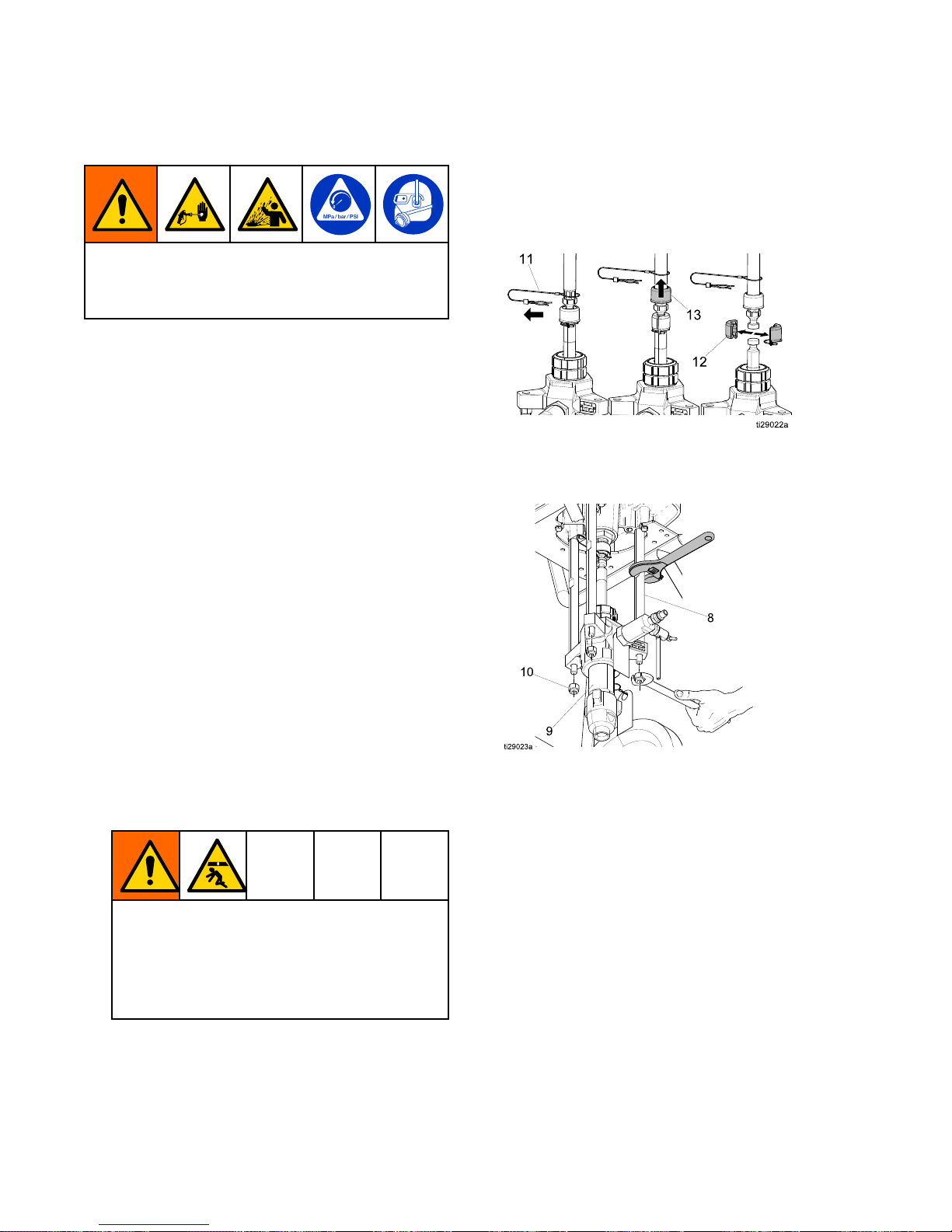
6.Removeclip(11)andslidecouplingcover(13)
uptoremovecoupling(12).
7.Useawrenchtoholdthetierodatstokeep
rods(8)fromturning.Unscrewnuts(10)and
removethelower(9).
8.RefertotheXtremeLowermanual(311762)to
servicethelower.
9.Reconnectthelowerbyfollowingthedisconnect
stepsinreverseorder.
NOTE: NOTE:
NOTE:
Torquethenuts(10)to50–60ft-lb(68–81
N•m).
22
3A3164D
Page 23
Repair
Outlet Outlet
Outlet
Check Check
Check
Valves Valves
Valves
1.PerformPressureReliefProcedure,page12,and
disconnecttheunitfromthepowersourcebefore
removingorservicingtheoutletcheckvalve.
2.Whenreplacingtheoutletcheckvalve,reinstall
withtheproperowdirection.
Outlet Outlet
Outlet
Check Check
Check
Valve Valve
Valve
Repair Repair
Repair
1.Flushthepump(seePrime/Flush,page13).
Stopthepumpatthebottomofthestroke.
2.PerformPressureReliefProcedure,page12.
3.Disconnecttheunitfromthepowersource.
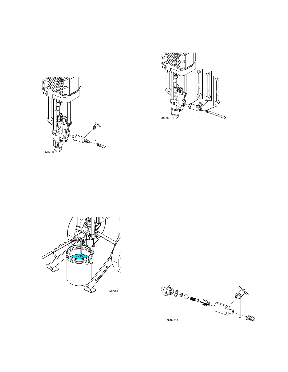
4.Placeawastecontainerbelowtheoutletcheck
valvetocatchanymaterial.
5.Usetwowrenchestoloosenthehose,then
disconnectthehosefromtheoutletcheckvalve
housing.
6.Useawrenchtoloosentheoutletcheckvalve,
thenremovetheoutletcheckvalvefromthe
pumplower.
NOTE: NOTE:
NOTE:
Thepressuredrainvalvemayremain
attachedtotheoutletcheckvalvehousingduring
repairifneeded.
7.Removetheoutletcheckvalvenutfromthevalve
housing.
8.Removeandcleanallinternaloutletcheckvalve
components.Inspectallcomponentsforwearor
damageandreplacecomponentsasneeded.
9.Reassemblepartsinthereverseorderthey
wereremoved;ballguides(3),springretainer,
compressorspring,andball.Useasmallblunt
tooltopushthatballinandverifythattheball
andspringmovefreely.
10.Replacetheo-ringandcoatwithgrease.
11.Torquetheoutletcheckvalvenutontothe
housingto75–80ft-lb(101–108N•m).
NOTE: NOTE:
NOTE:
Ifthepressuredrainvalvewasremoved
fortheoutletcheckvalverepair,reinstallatthis
point.
12.Reattachtheoutletcheckvalvetothepump
lowerandverifytheowindicationarrowis
pointingawayfromthepumpandthatthe
pressuredrainvalveoutletisfacingtheground.
13.Attachthedispensehosetotheoutletcheck
valve.
3A3164D 23
Page 24
Parts
Parts Parts
Parts
Parts Parts
Parts
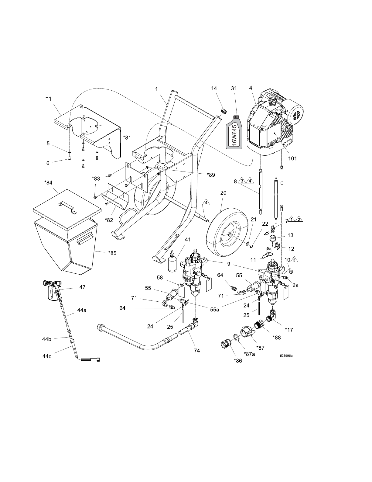
Drawing Drawing
Drawing
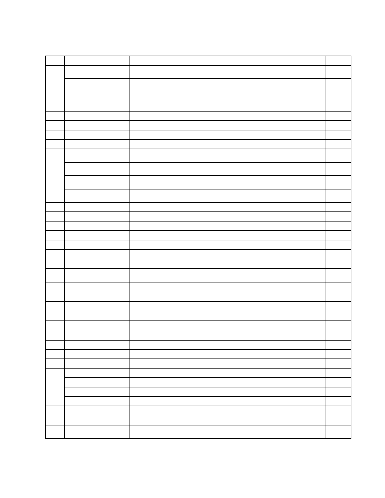
For information on Warning Labels, see Driver Operation/Repair manual.
Quick Start Guide 3A3067 (not shown) is available upon request.
†
Wall mount sprayers only.
24
3A3164D
Page 25
Parts
Parts Parts
Parts
List List
List
Ref. Ref.
Ref.
Part Part
Part
Description Description
Description
Qty. Qty.
Qty.
255143(includes5,6)BRACKET,wallmount,painted(Models24Y909,24Y910,24Y911,24Y912,
24Z909,24Z910,24Z911,24Z912
1
1
24Y078
(includes14,20,21,22)
CART,heavyduty,painted(Models24Y901,24Y902,24Y903,24Y904,
24Y905,24Y906,24Y907,24Y908,24Z901,24Z902,24Z903,24Z904,
24Z905,24Z906,24Z907,24Z908)
1
4
24X901(includes2x31
Oiljugs,part16W645)
DRIVER,e-Xtreme1
5
100133
WASHER,lock,3/8
4
6100101
SCREW,cap,hexhd
4
7
15H392
ROD,adapterXtreme
1
8257150
ROD,tie,141/4long
3
L145CN(includes9a)LOWER,Xtreme,145,nf,xseal,disk(Models24Y903,24Y904,24Y907,
24Y908,24Y911,24Y912)
1
L145CL(includes9a)LOWER,Xtreme,145,w/lt,xseal(Models24Y901,24Y902,24Y905,
24Y906,24Y909,24Y910)
1
L180CN(includes9a)LOWER,Xtreme,180,nf,xseal,disk(Models24Z903,24Z904,24Z907,
24Z908,24Z911,24Z912)
1
9
L180CL(includes9a)LOWER,Xtreme,180,w/lt,xseal(Models24Z901,24Z902,24Z905,
24Z906,24Z909,24Z910)
1
9a258962
HOUSING,rupturedisc,assembly
1
10101712NUT,lock3
11244820
CLIP,hairpin(w/lanyard)
1
12244819
COUPLING,assembly,145-290Xtreme
1
13197340
COVER,coupler
1
14113361
CAP,tube,round(Models24Y901,24Y902,24Y903,24Y904,24Y905,
24Y906,24Y907,24Y908,24Z901,24Z902,24Z903,24Z904,24Z905,
24Z906,24Z907,24Z908)
2
17*
17L151
FITTING,elbow(Models24Y905,24Y906,24Y907,24Y908,24Z905,
24Z906,24Z907,24Z908)
1
20113362
WHEEL,semi-pneumatic(Models24Y901,24Y902,24Y903,24Y904,
24Y905,24Y906,24Y907,24Y908,24Z901,24Z902,24Z903,24Z904,
24Z905,24Z906,24Z907,24Z908)
2
21154628
WASHER(Models24Y901,24Y902,24Y903,24Y904,24Y905,24Y906,
24Y907,24Y908,24Z901,24Z902,24Z903,24Z904,24Z905,24Z906,
24Z907,24Z908)
2
22113436
RING,retaining(Models24Y901,24Y902,24Y903,24Y904,24Y905,
24Y906,24Y907,24Y908,24Z901,24Z902,24Z903,24Z904,24Z905,
24Z906,24Z907,24Z908)
2
24116746
FITTING,barbed,plated
1
25116750TUBE,nylon1
31‡16W645
KIT,oil(1quartBottle)
206994
FLUID,TSL8oz
1
206995(notincluded)FLUID,TSL1quart(notshown)
206996(notincluded)FLUID,TSL1gallon(notshown)
41
206997(notincluded)FLUID,TSL12quarts(notshown)
44aH42506
HOSE,cpld,4500psi,0.25ID,6ft(Models24Y901,24Y903,24Y905,
24Y907,24Y909,24Y911,24Z901,24Z903,24Z905,24Z907,24Z909,
24Z911)
1
44b164856
FITTING,nipple,reducing(Models24Y901,24Y903,24Y905,24Y907,
24Y909,24Y911,24Z901,24Z903,24Z905,24Z907,24Z909,24Z911)
1
3A3164D 25
Page 26

Parts
Ref. Ref.
Ref.
Part Part
Part
Description Description
Description
Qty. Qty.
Qty.
44cH43850
HOSE,cpld,4500psi,0.375ID,50ft(Models24Y901,24Y903,24Y905,
24Y907,24Y909,24Y911,24Z901,24Z903,24Z905,24Z907,24Z909,
24Z911)
1
47XTR504
GUN,XTR5,1in.hnd,4fng,xhdrac(Models24Y901,24Y903,24Y905,
24Y907,24Y909,24Y911,24Z901,24Z903,24Z905,24Z907,24Z909,
24Z911)
1
25C189(1/2in.NPTfor
IntegratedlterLowers)
VALVE,subassembly(Models24Y901,24Y902,24Y905,24Y906,24Y909,
24Y910,24Z901,24Z902,24Z905,24Z906,24Z909,24Z910)
1
55
127631(3/4in.NPTfor
Nolterlowers)
VALVE,subassembly(Models24Y903,24Y904,.24Y907,24Y908,24Y911,
24Y912,24Z903,24Z904,24Z907,24Z908,24Z911,24Z912)
1
55a
245143VALVE,pressure,bleed1
5817A411LABEL,instructions1
64162505
FITTING,union,swivel
1
71*C19024FITTING,elbow,swivel(Models24Y905,24Y906,24Y907,24Y908,24Z905,
24Z906,24Z907,24Z908)
1
7424Z274
HOSE,suction,1in.nptx3ftL(Models24Y901,24Y902,24Y903,24Y904,
24Z901,24Z902,24Z903,24Z904)
1
81*
17D554
BRACKET,hopper,upper(Models24Y905,24Y906,24Y907,24Y908,
24Z905,24Z906,24Z907,24Z908)
1
82*17C474BRACKET,hopper(Models24Y905,24Y906,24Y907,24Y908,24Z905,
24Z906,24Z907,24Z908)
1
83*
112395
SCREW,cap,nghd(Models24Y905,24Y906,24Y907,24Y908,24Z905,
24Z906,24Z907,24Z908)
4
84*
16U537
COVER,complete(Models24Y905,24Y906,24Y907,24Y908,24Z905,
24Z906,24Z907,24Z908)
1
85*
17E114
HOPPER,weldment,Xtreme(Models24Y905,24Y906,24Y907,24Y908,
24Z905,24Z906,24Z907,24Z908)
1
86*
120307
FITTING,hoseadapter,male(Models24Y905,24Y906,24Y907,24Y908,
24Z905,24Z906,24Z907,24Z908)
1
87*
120308
FITTING,hoseadapter,female(Models24Y905,24Y906,24Y907,24Y908,
24Z905,24Z906,24Z907,24Z908)
1
87a*120781(PTFE
EncapsulatedViton)
GASKET,quickcoupler(Models24Y905,24Y906,24Y907,24Y908,24Z905,
24Z906,24Z907,24Z908)
1
87b*17C453(Buna-N6-pack)
(notincludedwith87)
GASKET,quickcoupler(6-PACK)(Models24Y905,24Y906,24Y907,
24Y908,24Z905,24Z906,24Z907,24Z908)(notshown)
1
88*
17L152
FITTING,swivel(Models24Y905,24Y906,24Y907,24Y908,24Z905,
24Z906,24Z907,24Z908)
1
89*
112958
NUT,hex,anged(Models24Y905,24Y906,24Y907,24Y908,24Z905,
24Z906,24Z907,24Z908)
4
101▲17J476
LABEL,warning(English/French/Spanish)
1
17K430
LABEL,warning,bag(Dutch/German/Swedish,Polish/Russian,
Italian/Turkish)
1
*
Included in Hopper Accessory Kit 25C188
▲
Additional Warning labels are available at no cost.
‡Thedrivergearboxisshippedfromthefactorypre-lledwithoil.Additionaloilmustbepurchasedseparately.
1
Torqueto145–155ft-lb(196–210N•m).
2
Applythreadlocker.
3
Torqueto56–60ft-lb68–81N•m).
4
Applylithiumgreaselubricant.
26 3A3164D
Page 27
Parts
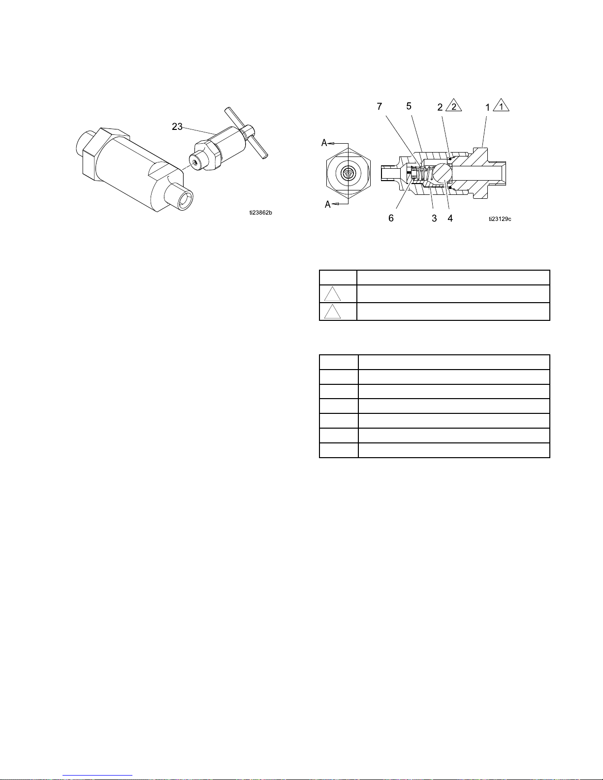
Outlet Outlet
Outlet
Check Check
Check
Valves Valves
Valves
Parts Parts
Parts
Outlet Outlet
Outlet
Check Check
Check
Valves Valves
Valves
Parts Parts
Parts
List: List:
List:
127631 127631
127631
(3/4 (3/4
(3/4
in. in.
in.
male male
male
npt npt
npt
inlet) inlet)
inlet)
25C189 25C189
25C189
(1/2 (1/2
(1/2
in. in.
in.
male male
male
npt npt
npt
inlet) inlet)
inlet)
Ref. Ref.
Ref.
Part Part
Part
Description Description
Description
Qty. Qty.
Qty.
1127882
NUT,seat(includes2*and4)for
187631version
1
25C190NUT,seat(includes2*and4)for
25C189version
1
2*
102595
PACKING,o-ring
1
3181492
GUIDE,ball
3
4102972BALL,metallic1
5
17A091
HOUSING,ball,check
1
6181535RETAINER,spring1
7
108361
SPRING,compressor
1
23245143VALVE,pressurebleed1
*
If the outlet check valve is disassembled, the o - ring (2) must be
replaced. The o - ring is designed to be crushed, and not reused.
Parts Parts
Parts
Specications: Specications:
Specications:
Ref. Ref.
Ref.
Instruction Instruction
Instruction
1
Torqueto101–108N•m(75–80ft-lb)
2
Applylubricant
Accessories: Accessories:
Accessories:
Part Part
Part
Description Description
Description
17B291
MIXER,jiffy,PS-1
24Z266
KIT,suctionset,1in.nptx6ftL
24Z274
KIT,suctionset,1in.nptx3ftL
24Z270
KIT,suction,drum,1in.nptx10ftL
17M677
SoftwareUpdateToken**
25C188
KIT,hopper(seePartsListforcontents)
**
See the Driver Operation/Repair manual for “ Software Software
Software
Token Token
Token
Update Update
Update
” procedure.
3A3164D
27
Page 28
Parts
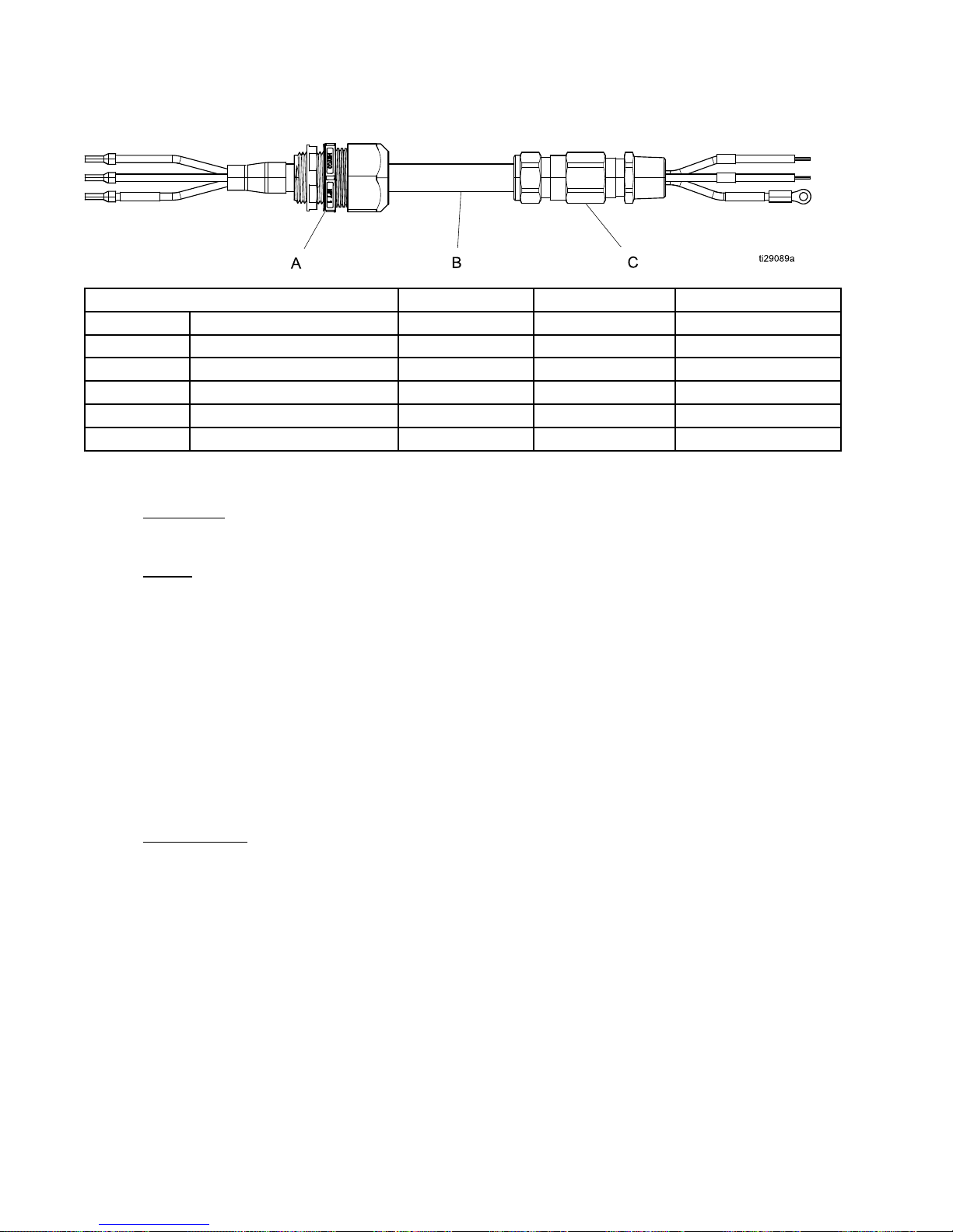
ATEX/Hazardous ATEX/Hazardous
ATEX/Hazardous
Location-Rated Location-Rated
Location-Rated
Power Power
Power
Cord Cord
Cord
Kits Kits
Kits
(1–gland (1–gland
(1–gland
cable cable
cable
shown) shown)
shown)
ATEX/Hazardous ATEX/Hazardous
ATEX/Hazardous
Location Location
Location
- --Rated Rated
Rated
Power Power
Power
Cords: Cords:
Cords:
A AA– ––Cord Cord
Cord
Grip Grip
Grip
B BB– ––Cable Cable
Cable
C CC– ––Cable Cable
Cable
Gland Gland
Gland
24Z267*
KIT,powercable,1gland,8M
111
24Z268*
KIT,powercable,1gland,15M
111
24Z269*
KIT,powercable,1gland,30M
111
24Z271
KIT,powercable,2gland,8M
—
12
24Z272
KIT,powercable,2gland,15M
—
12
24Z273
KIT,powercable,2gland,30M
—
12
*
Only one end has ATEX/Hazardous location cable gland. Power Supply must be outside of ATEX/Hazardous location for ratings to apply.
A: A:
A:
Cord Cord
Cord
Grip Grip
Grip
(ordinary (ordinary
(ordinary
location) location)
location)
PowerSupplymustbeoutsideofATEX/Hazardouslocationforratingstoapply.
B: B:
B:
Cable Cable
Cable
MOR® MOR®
MOR®
Polyrad® Polyrad®
Polyrad®
XT XT
XT
- --125 125
125
Armored Armored
Armored
and and
and
Sheathed Sheathed
Sheathed
Cable Cable
Cable
(125° (125°
(125°
C CCTemperature Temperature
Temperature
Rating) Rating)
Rating)
Manufacturer:GeneralCable
ManufacturerP/N:279220
UL UL
UL
1309 1309
1309
Type Type
Type
X110 X110
X110
(UL (UL
(UL
Listed Listed
Listed
File File
File
No. No.
No.
E85994) E85994)
E85994)
IEEE IEEE
IEEE
1580 1580
1580
Type Type
Type
P P
P
CSA CSA
CSA
C22.2 C22.2
C22.2
No. No.
No.
245 245
245
Type Type
Type
X110 X110
X110
IEC IEC
IEC
60092 60092
60092
– ––350 350
350
API API
API
- --RP14F*** RP14F***
RP14F***
***PermanufacturerGeneralCable,suitableforuseinClassI,Division1,andZone1HazardousLocations
wheninstalledinaccordancewithAPI-RP14F.Cableglandratingsmayhaveaneffectonoverallratings
andmustalsobeconsidered.
Forotherratings,listingsandinstallationinstructionsseemanufacturer’swebsite:http://www.generalcable.com/
C: C:
C:
Cable Cable
Cable
Gland Gland
Gland
– ––for for
for
driver, driver,
driver,
with with
with
ratings ratings
ratings
CROCLOCK CROCLOCK
CROCLOCK
®Cable Cable
Cable
Gland Gland
Gland
Manufacturer:PeppersCableGlands
ManufacturerP/N:CR-3B/NP/20/075NPT
Certicate Certicate
Certicate
No. No.
No.
ABS: ABS:
ABS:
09–LD463991–PDA 09–LD463991–PDA
09–LD463991–PDA
(American (American
(American
Bureau Bureau
Bureau
of ofofShipping) Shipping)
Shipping)
CSA: CSA:
CSA:
1356011 1356011
1356011
•Ex Ex
Ex
d ddIIc IIc
IIc
/ //Ex Ex
Ex
e eeII IIIIClass Class
Class
I IIZone Zone
Zone
1 1
1
•Class Class
Class
I IIDivision Division
Division
2, 2,2,Groups Groups
Groups
A, A,
A,
B, B,
B,
C CCand and
and
D D
D
ATEX: ATEX:
ATEX:
BAS BAS
BAS
01ATEXT2271X 01ATEXT2271X
01ATEXT2271X
IECEx: IECEx:
IECEx:
SIR SIR
SIR
07.0099X 07.0099X
07.0099X
Foradditionalcerticates/listingsandinstallationinstructions,seemanufacturer’swebsite:
http://peppersamerica.com/
28 3A3164D
Page 29
Dimensions
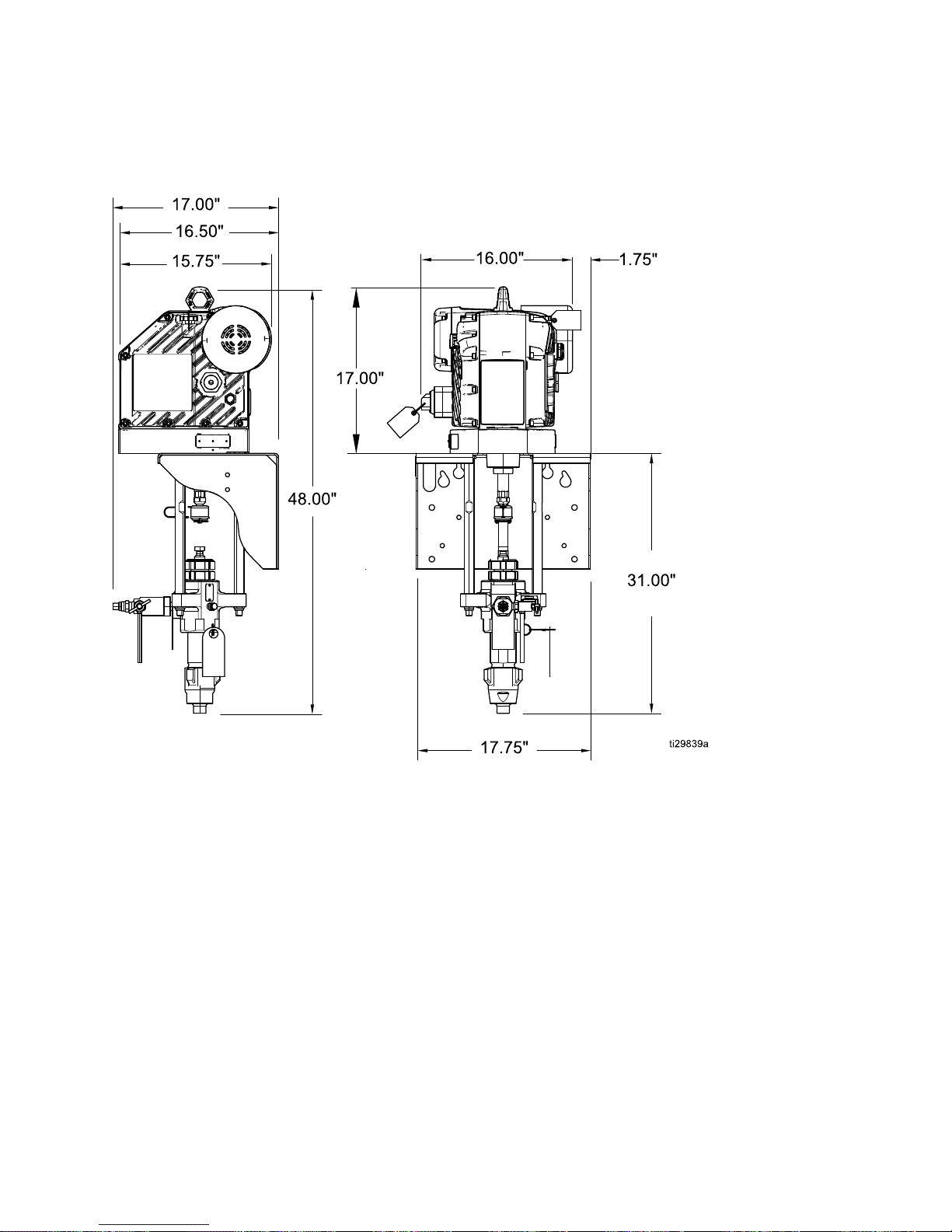
Dimensions Dimensions
Dimensions
Wall Wall
Wall
Mount Mount
Mount
Systems Systems
Systems
3A3164D 29
Page 30
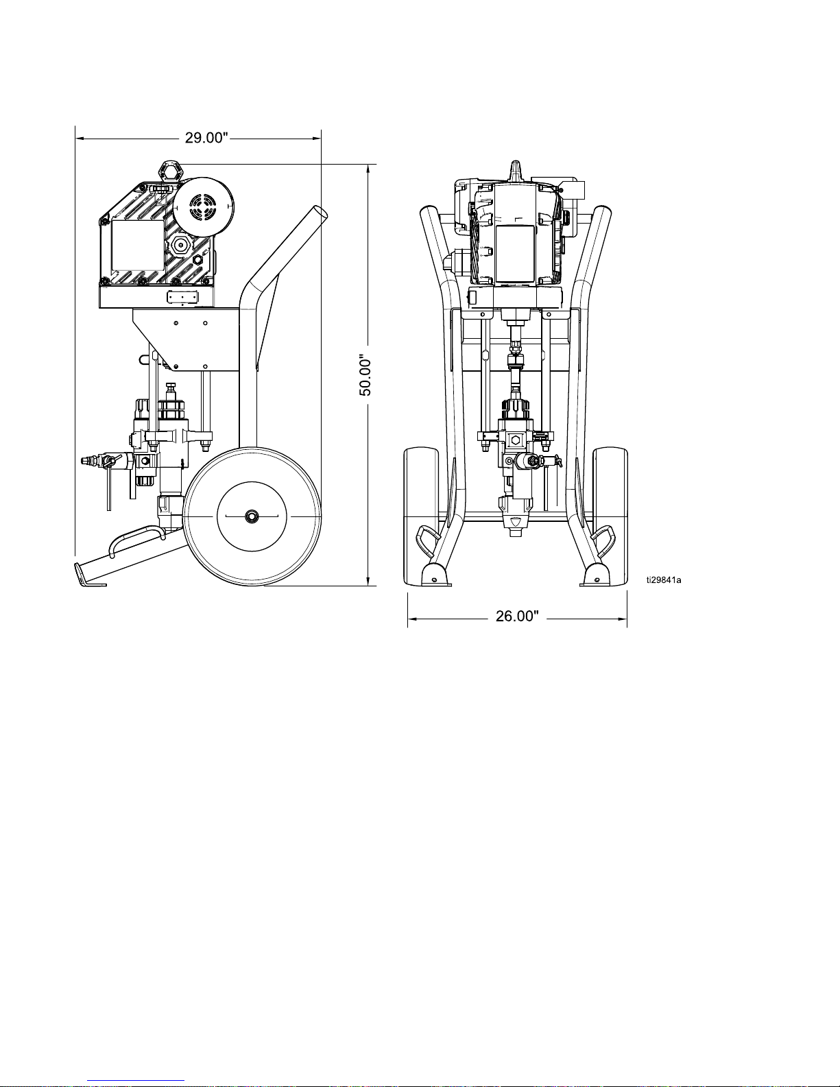
Dimensions
Cart Cart
Cart
Systems Systems
Systems
30 3A3164D
Page 31
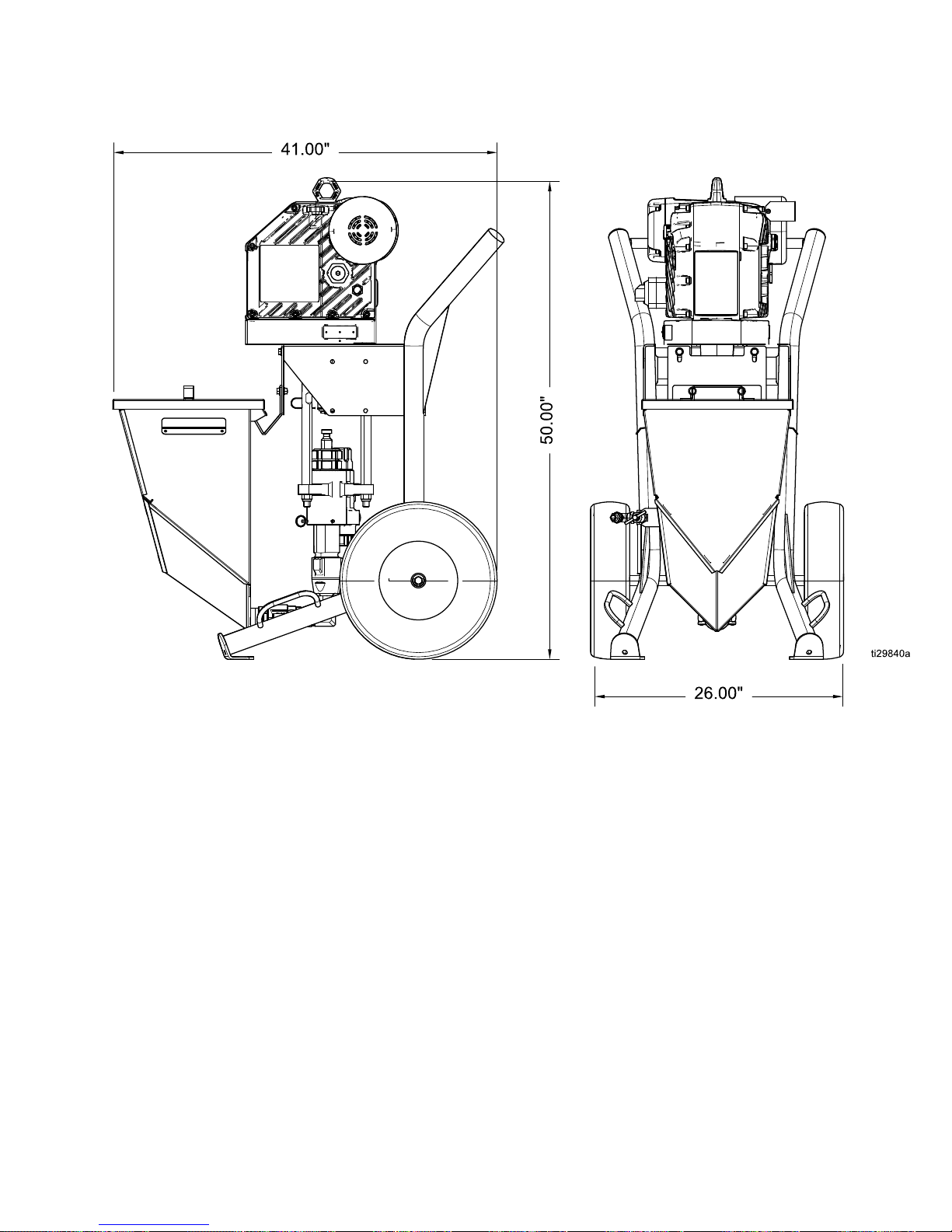
Dimensions
Hopper Hopper
Hopper
Systems Systems
Systems
3A3164D 31
Page 32
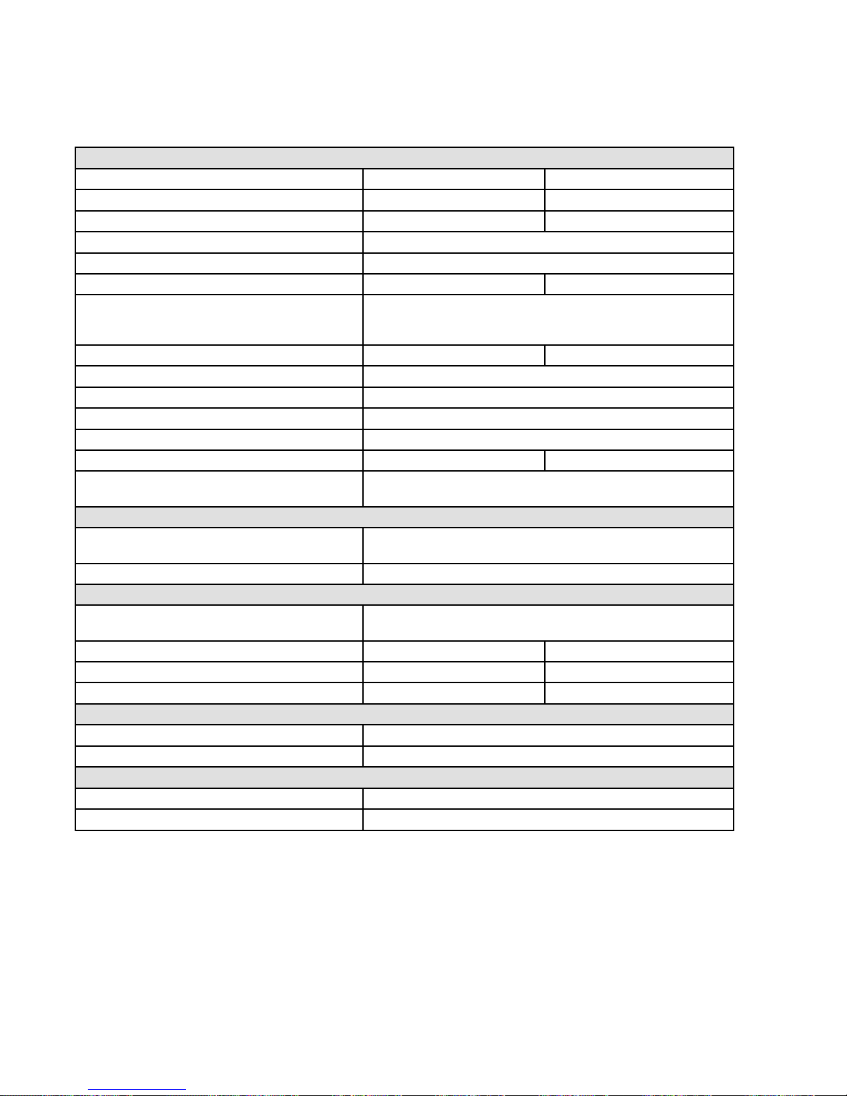
TechnicalSpecications
Technical Technical
Technical
Specications Specications
Specications
Ex35 Ex35
Ex35
e ee- --Xtreme Xtreme
Xtreme
Sprayers Sprayers
Sprayers
U.S. U.S.
U.S.
Metric Metric
Metric
Maximumuidworkingpressure
3500psi240bar,24.0MPa
Strokelength
4.75in.120mm
Maximumcontinuouscyclerate44cyclesperminute
TipSize
.023in.
Weight295lb135kg
Wettedparts
CarbonSteel,AlloySteel,304,440and17–PHGrades
ofStainlessSteel,ZincandNickelPlating,DuctileIron,
TungstenCarbide,PTFE;Leather,Aluminum
Operatingtemperaturerange23°to120°F-5°to50°C
MaximumuidtemperatureSeeModelsinformationinOperation/Repairmanual.
Inputvoltage
200–240VAC,singlephase,50/60Hz
Inputpower2.5kVA
MinimumRecommendedgeneratorsize5kW
Oilcapacity
1.0–1.2quarts0.9–1.1liters
OilspecicationGracopartnumber16W645silicone-freeISO
220syntheticEPgearoil
Inlet/OutletSizes
Fluidinletsize
1in.npt(m)[alsoincludes1in.nps(swivel)to
1in.npt(m)adapterelbow]
Fluidoutletsize
1/2npt(m)[alsoincludes1/2npt(f)to3/8npt(m)adapter]
HoseRequirements
MinimumpressureTheminimumhosepressureratingshouldbeequaltoor
greaterthanthemaximumuidworkingpressureofsprayer
Minimumlength
50ft.
15m
MinimumID3/8in.10mm
MaximumresistanceperISO80289,100ohms/ft
30,000ohms/m
SoundEmissions(perISO9614)forNormalOperation(Spraying@20cpm)
SoundPressureLpAAverage
70.2dBA
SoundPowerLwATotalPower
76.7dBA
SoundEmissions(perISO9614)forMaximumSpeed(Flushing@44cpm)
SoundPressureLpAAverage
77.4dBA
SoundPowerLwATotalPower
85.1dBA
32 3A3164D
Page 33
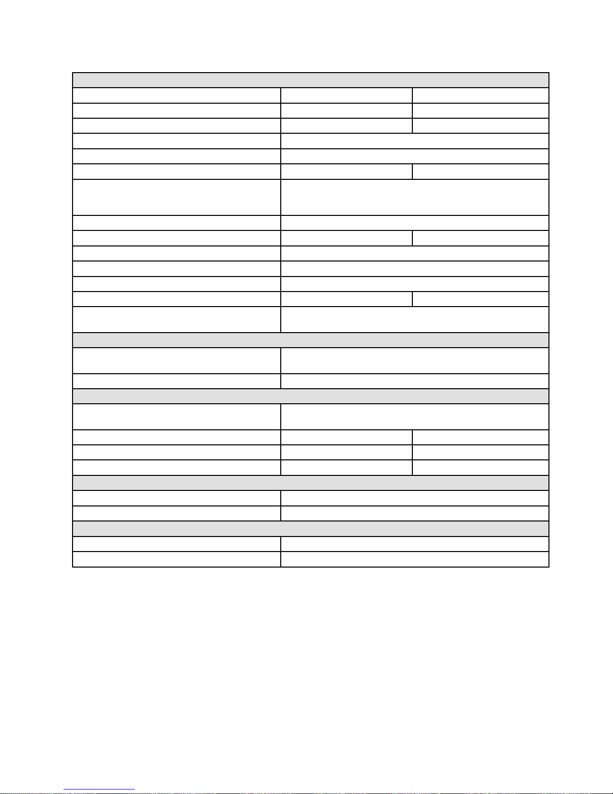
TechnicalSpecications
Ex45 Ex45
Ex45
e ee- --Xtreme Xtreme
Xtreme
Sprayers Sprayers
Sprayers
U.S. U.S.
U.S.
Metric Metric
Metric
Maximumuidworkingpressure
4500psi310bar,31.0MPa
Strokelength
4.75in.120mm
Maximumcontinuouscyclerate44cyclesperminute
TipSize
.021in.
Weight295lb135kg
Wettedparts
CarbonSteel,AlloySteel,304,440and17–PHGrades
ofStainlessSteel,ZincandNickelPlating,DuctileIron,
TungstenCarbide,PTFE;Leather,Aluminum
MaximumuidtemperatureSeeModelsinformationinOperation/Repairmanual.
Operatingtemperaturerange23°to120°F-5°to50°C
Inputvoltage
200–240VAC,singlephase,50/60Hz
Inputpower2.5kVA
MinimumRecommendedgeneratorsize5kW
Oilcapacity
1.0–1.2quarts0.9–1.1liters
OilspecicationGracopartnumber16W645silicone-freeISO
220syntheticEPgearoil
Inlet/OutletSizes
Fluidinletsize
1in.npt(m)[alsoincludes1in.nps(swivel)to
1in.npt(m)adapterelbow]
Fluidoutletsize
1/2npt(m)[alsoincludes1/2npt(f)to3/8npt(m)adapter]
HoseRequirements
MinimumpressureTheminimumhosepressureratingshouldbeequaltoor
greaterthanthemaximumuidworkingpressureofsprayer
Minimumlength
50ft.
15m
MinimumID3/8in.10mm
MaximumresistanceperISO80289,100ohms/ft
30,000ohms/m
SoundEmissions(perISO9614)forNormalOperation(Spraying@20cpm)
SoundPressureLpAAverage
70.2dBA
SoundPowerLwATotalPower
76.7dBA
SoundEmissions(perISO9614)forMaximumSpeed(Flushing@44cpm)
SoundPressureLpAAverage
77.4dBA
SoundPowerLwATotalPower
85.1dBA
3A3164D 33
Page 34

Graco Graco
Graco
Standard Standard
Standard
Warranty Warranty
Warranty
GracowarrantsallequipmentreferencedinthisdocumentwhichismanufacturedbyGracoandbearingits
nametobefreefromdefectsinmaterialandworkmanshiponthedateofsaletotheoriginalpurchaserfor
use.Withtheexceptionofanyspecial,extended,orlimitedwarrantypublishedbyGraco,Gracowill,fora
periodoftwelvemonthsfromthedateofsale,repairorreplaceanypartoftheequipmentdetermined
byGracotobedefective.Thiswarrantyappliesonlywhentheequipmentisinstalled,operatedand
maintainedinaccordancewithGraco’swrittenrecommendations.
Thiswarrantydoesnotcover,andGracoshallnotbeliableforgeneralwearandtear,oranymalfunction,
damageorwearcausedbyfaultyinstallation,misapplication,abrasion,corrosion,inadequateorimproper
maintenance,negligence,accident,tampering,orsubstitutionofnon-Gracocomponentparts.Norshall
Gracobeliableformalfunction,damageorwearcausedbytheincompatibilityofGracoequipment
withstructures,accessories,equipmentormaterialsnotsuppliedbyGraco,ortheimproperdesign,
manufacture,installation,operationormaintenanceofstructures,accessories,equipmentormaterials
notsuppliedbyGraco.
Thiswarrantyisconditionedupontheprepaidreturnoftheequipmentclaimedtobedefectivetoan
authorizedGracodistributorforvericationoftheclaimeddefect.Iftheclaimeddefectisveried,Graco
willrepairorreplacefreeofchargeanydefectiveparts.Theequipmentwillbereturnedtotheoriginal
purchasertransportationprepaid.Ifinspectionoftheequipmentdoesnotdiscloseanydefectinmaterial
orworkmanship,repairswillbemadeatareasonablecharge,whichchargesmayincludethecostsof
parts,labor,andtransportation.
THISWARRANTYISEXCLUSIVE,ANDISINLIEUOFANYOTHERWARRANTIES,EXPRESSOR
IMPLIED,INCLUDINGBUTNOTLIMITEDTOWARRANTYOFMERCHANTABILITYORWARRANTY
OFFITNESSFORAPARTICULARPURPOSE.
Graco’ssoleobligationandbuyer’ssoleremedyforanybreachofwarrantyshallbeassetforthabove.
Thebuyeragreesthatnootherremedy(including,butnotlimitedto,incidentalorconsequentialdamages
forlostprots,lostsales,injurytopersonorproperty,oranyotherincidentalorconsequentialloss)shall
beavailable.Anyactionforbreachofwarrantymustbebroughtwithintwo(2)yearsofthedateofsale.
GRACO GRACO
GRACO
MAKES MAKES
MAKES
NO NO
NO
WARRANTY, WARRANTY,
WARRANTY,
AND AND
AND
DISCLAIMS DISCLAIMS
DISCLAIMS
ALL ALL
ALL
IMPLIED IMPLIED
IMPLIED
WARRANTIES WARRANTIES
WARRANTIES
OF OF
OF
MERCHANTABILITY MERCHANTABILITY
MERCHANTABILITY
AND AND
AND
FITNESS FITNESS
FITNESS
FOR FOR
FOR
A AAPARTICULAR PARTICULAR
PARTICULAR
PURPOSE, PURPOSE,
PURPOSE,
IN IN
IN
CONNECTION CONNECTION
CONNECTION
WITH WITH
WITH
ACCESSORIES, ACCESSORIES,
ACCESSORIES,
EQUIPMENT, EQUIPMENT,
EQUIPMENT,
MATERIALS MATERIALS
MATERIALS
OR OR
OR
COMPONENTS COMPONENTS
COMPONENTS
SOLD SOLD
SOLD
BUT BUT
BUT
NOT NOT
NOT
MANUFACTURED MANUFACTURED
MANUFACTURED
BY BY
BY
GRACO. GRACO.
GRACO.
Theseitemssold,butnotmanufacturedbyGraco(suchaselectricmotors,switches,hose,etc.),
aresubjecttothewarranty,ifany,oftheirmanufacturer.Gracowillprovidepurchaserwithreasonable
assistanceinmakinganyclaimforbreachofthesewarranties.
InnoeventwillGracobeliableforindirect,incidental,specialorconsequentialdamagesresultingfrom
Gracosupplyingequipmenthereunder,orthefurnishing,performance,oruseofanyproductsorother
goodssoldhereto,whetherduetoabreachofcontract,breachofwarranty,thenegligenceofGraco,or
otherwise.
FORGRACOCANADACUSTOMERS
ThePartiesacknowledgethattheyhaverequiredthatthepresentdocument,aswellasalldocuments,
noticesandlegalproceedingsenteredinto,givenorinstitutedpursuantheretoorrelatingdirectlyor
indirectlyhereto,bedrawnupinEnglish.Lespartiesreconnaissentavoirconvenuquelarédactiondu
présentedocumentseraenAnglais,ainsiquetousdocuments,avisetprocéduresjudiciairesexécutés,
donnésouintentés,àlasuitedeouenrapport,directementouindirectement,aveclesprocédures
concernées.
Graco Graco
Graco
Information Information
Information
ForthelatestinformationaboutGracoproducts,visitwww.graco.com.
Forpatentinformation,seewww.graco.com/patents.
To To
To
place place
place
an an
an
order, order,
order,
contactyourGracoDistributororcalltoidentifythenearestdistributor.
Phone: Phone:
Phone:
612-623-6921or or
or
Toll Toll
Toll
Free: Free:
Free:
1-800-328-0211Fax: Fax:
Fax:
612-378-3505
Allwrittenandvisualdatacontainedinthisdocumentreectsthelatestproductinformationavailableatthetimeofpublication.
Gracoreservestherighttomakechangesatanytimewithoutnotice.
OriginalInstructions.ThismanualcontainsEnglish,MM3A3164
Graco Graco
Graco
Headquarters: Headquarters:
Headquarters:
Minneapolis
International International
International
Ofces: Ofces:
Ofces:
Belgium,China,Japan,Korea
GRACO GRACO
GRACO
INC. INC.
INC.
AND AND
AND
SUBSIDIARIES SUBSIDIARIES
SUBSIDIARIES
• ••P.O. P.O.
P.O.
BOX BOX
BOX
1441 1441
1441
• ••MINNEAPOLIS, MINNEAPOLIS,
MINNEAPOLIS,
MN MN
MN
55440-1441 55440-1441
55440-1441
• ••USA USA
USA
Copyright Copyright
Copyright
2016, 2016,
2016,
Graco Graco
Graco
Inc. Inc.
Inc.
All All
All
Graco Graco
Graco
manufacturing manufacturing
manufacturing
locations locations
locations
are are
are
registered registered
registered
to totoISO ISO
ISO
9001. 9001.
9001.
www.graco.com
RevisionD–March2017
 Loading...