

Graco EnergyComplete 313221H Instructions - Parts Manual
Instructions & Part s
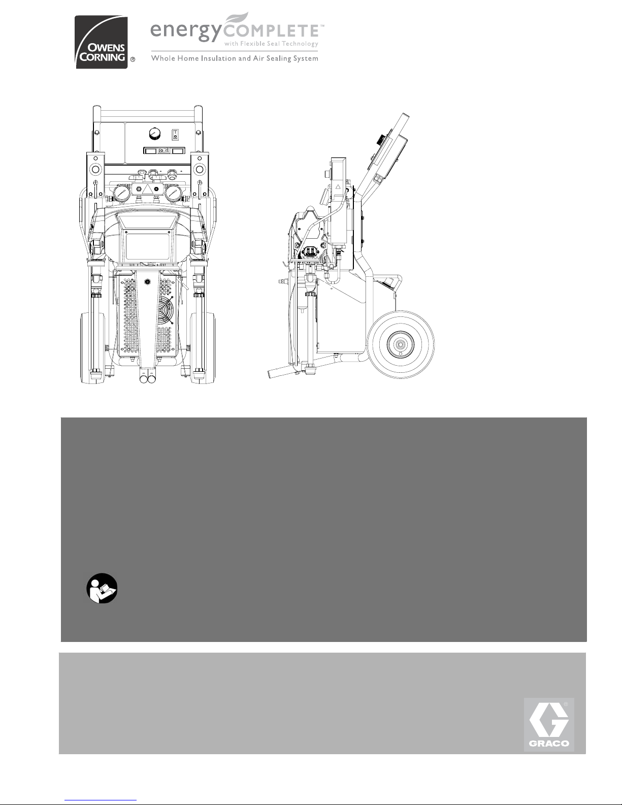
r_256765_313221_39b r_256765_313221_38b
EnergyComplete™ Sprayer
Manual No:
For use with EnergyComplete Air Infiltration Barrier with Flexible Seal T echnology.
Not for use in explosive atmospheres or with flammable materials.
Important Safety Instructions
Read all warnings and instructions in this manual.
Save these instructions.
EnergyComplete Sprayer Packages
313221H
257125 Heated Package
257126 Heated Package with compressor
See page 4 for a list of models, approvals, and maximum working pressures.

Contents
Related Manuals . . . . . . . . . . . . . . . . . . . . . . . . . . . 3
Models . . . . . . . . . . . . . . . . . . . . . . . . . . . . . . . . . . . 4
Warnings . . . . . . . . . . . . . . . . . . . . . . . . . . . . . . . . . 5
Overview . . . . . . . . . . . . . . . . . . . . . . . . . . . . . . . . . . 7
Keep Components A and B Separate . . . . . . . . . . 7
Compatible Solvents . . . . . . . . . . . . . . . . . . . . . . . . 7
Ene rgy Comp l et e Ai r Infiltra tion Bar rie r Temp era tu re
Requirements . . . . . . . . . . . . . . . . . . . . . . . . . . 7
Component Identification . . . . . . . . . . . . . . . . . . . . 8
Controls and Indicators . . . . . . . . . . . . . . . . . . . . . 9
Motor/Pump Control Function Knob . . . . . . . . . . 9
STATUS In d ica to r . . . . . . . . . . . . . . . . . . . . . . . . 9
Mot o r P o wer S witch /C ircu it Bre a k e r . . . . . . . . . . 9
Heater Powe r S wit c h /Cir c u i t Br e a ker . . . . . . . . 10
Heater Temperature Controls . . . . . . . . . . . . . . 10
Fluid Temperature Sensors and Displays . . . . . 10
Air Compressor Power Switch/Circuit Breaker . 11
Air Compressor Controls . . . . . . . . . . . . . . . . . . 11
Setup . . . . . . . . . . . . . . . . . . . . . . . . . . . . . . . . . . . . 12
Preheat Hoses . . . . . . . . . . . . . . . . . . . . . . . . . 17
Startup . . . . . . . . . . . . . . . . . . . . . . . . . . . . . . . . . . 18
Spr a y ing/Dis p e n s ing . . . . . . . . . . . . . . . . . . . . . . . 19
Pause . . . . . . . . . . . . . . . . . . . . . . . . . . . . . . . . . . . 20
Pressure Reli ef Procedure . . . . . . . . . . . . . . . . . . 21
Shutdow n . . . . . . . . . . . . . . . . . . . . . . . . . . . . . . . . 21
Maintenance . . . . . . . . . . . . . . . . . . . . . . . . . . . . . .22
Flushing . . . . . . . . . . . . . . . . . . . . . . . . . . . . . . . . . 23
Troubleshoo ting . . . . . . . . . . . . . . . . . . . . . . . . . . . 25
Status Codes . . . . . . . . . . . . . . . . . . . . . . . . . . . 25
Troubleshooting Chart . . . . . . . . . . . . . . . . . . . . 28
Repair . . . . . . . . . . . . . . . . . . . . . . . . . . . . . . . . . . .33
Before Beginning Repair . . . . . . . . . . . . . . . . . . 33
Recirc/Spray Valves . . . . . . . . . . . . . . . . . . . . . . 34
Disp lac e me n t Pump . . . . . . . . . . . . . . . . . . . . . 35
Control Module . . . . . . . . . . . . . . . . . . . . . . . . .37
Fluid Heaters . . . . . . . . . . . . . . . . . . . . . . . . . . .41
Pressure Transducers . . . . . . . . . . . . . . . . . . . . 41
Drive Housing . . . . . . . . . . . . . . . . . . . . . . . . . . 42
Cycle Counter Switch Replacement . . . . . . . . . 43
Electric Motor . . . . . . . . . . . . . . . . . . . . . . . . . . 44
Compressor . . . . . . . . . . . . . . . . . . . . . . . . . . . .45
Mot o r Bru s h e s . . . . . . . . . . . . . . . . . . . . . . . . . . 47
Fan . . . . . . . . . . . . . . . . . . . . . . . . . . . . . . . . . .47
Parts . . . . . . . . . . . . . . . . . . . . . . . . . . . . . . . . . . . . 48
Suggested Spar e Replacem ent Par ts . . . . . . . . . 57
Ac c ess o rie s . . . . . . . . . . . . . . . . . . . . . . . . . . . . . . 57
Dimensions . . . . . . . . . . . . . . . . . . . . . . . . . . . . . . . 58
Technical Data . . . . . . . . . . . . . . . . . . . . . . . . . . . . 59
Graco Standard Warranty . . . . . . . . . . . . . . . . . . .60
Gra c o In for ma tion . . . . . . . . . . . . . . . . . . . . . . . . .60
2 313221H

Related Manuals
Related Manuals
The following manuals are for EnergyComplete Sprayer components and accessories. Some are supplied with your
package, depending on its configuration. Manuals are available at www.part ner wi thpi nk. com.
EnergyComplete Spray Gun
Part No. Descriptio n
313294 Instruction-Parts Manual
A Side Displacement Pump - White Material
Part No. Descriptio n
313123 Instruction-Parts Manual
B Side Displace me nt Pump - Red Materi al
Part No. Descriptio n
313383 Instruction-Parts Manual
Fluid Heater
Part No. Descriptio n
311210 Instruction-Parts Manual
EnergyComplete Compressor Kit
Part No. Descriptio n
313457 Instruction-Parts Manual
313221H 3

Models
Models
The model no., series letter, and serial no. are located on the back of the EnergyComplete Spray er . For fast er assistance, please have that infor mation ready before calling Cust omer Ser vi c e.
Package
Sprayer
Model Volts
* Electrical
Connection Package Description
15 A cord
(motor)
257125 257089 120 V
15 A cord
(heaters)
15 A cord
(motor)
257126 256765 120 V
15 A cord
(heaters)
15 A cord
(compressor)
* See page 13 for detailed electrical requirements.
All EnergyComplete Sprayer packages are ETL approved.
Heated EnergyComplete Sprayer, insulated
3-hose bundle, Energy-
Complete Spray Gun,
circulation kit
Heated EnergyCom-
plete Sprayer, insulated
3-hose bundle, compres-
sor, EnergyComplete
Spray Gun, circulation kit
Maximum
Working
Pressure,
psi
(MPa, bar)
2000
(14, 140)
2000
(14, 140)
Maximum
Air Working
Pressure,
psi
(MP a , b a r )
100
(0.7, 7)
100
(0.7, 7)
#ONFORMSTO!.3)5,
3TD#ERTIFIEDTO
#!.#3!3TD
#.O
4 313221H
Warnings
Warnings
The following general warnings are for the setup, use, grounding, maintenance, and repair of this equipment. Additional, more specific warnings may be found throughout the body of this manual where applicable. Symbols appear-
ing in the body of the manual refer to these general warnin gs. When these symb ols appear throughout the manual,
refer back to these pages for a description of the specifi c hazard.
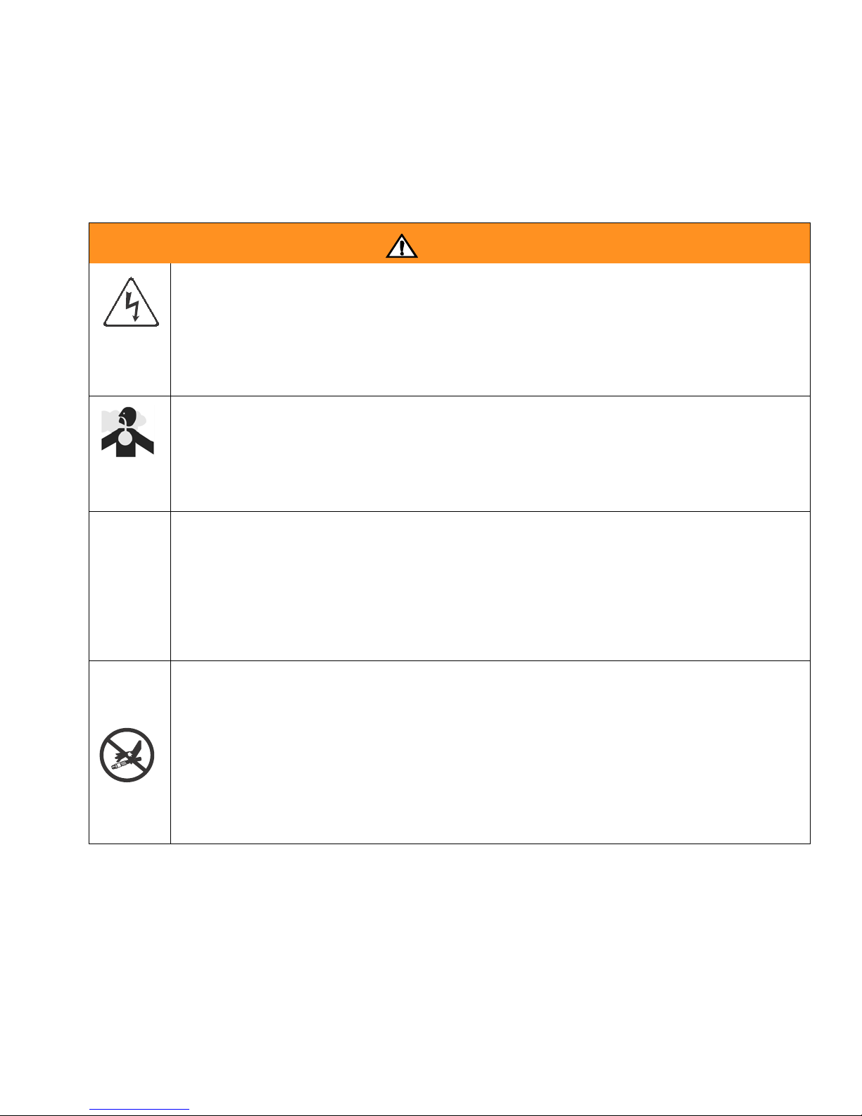
WARNING
ELECTRI C SHOCK HAZARD
Improper grounding, setup, or usage of the system can cause electric shock.
• Turn off and disconnect power cord before servici ng equipment.
• Use only grounded electrical outlets.
• Use only 3-wire extension cords.
• Ensure ground prongs are intact on sprayer and extension cords.
• Do not expose to rain. Store indoors.
TOXIC FLUID OR FUMES HAZARD
Toxic fluids or fumes can cause serious injury or death if splashed in the eyes or on skin, inhaled, or
swallowed.
• Read MSDS’s to know the specific hazar ds of the fluids you are using.
• Store hazar dous fluid in approved containers, and dispo se of it accordin g to applicable guide lines.
PERSONAL PROTECTI VE EQUIPM ENT
You must wear appropriate protective equipment when operating, servicing, or when in the operating
area of the equipment to help protect you from serious inj ur y, including eye injury, inhalation of toxic
fumes, burns, and hearing loss. This equipment includes but is not limited to:
• Protective ey ewear
• Clothing and respirato r as recommended by the fluid and solvent manufacturer
• Gloves
• Hearing protection
SKIN INJ ECTION HAZAR D
High-pressure fluid from gun, hose leaks, or ruptured components will pierce skin. This may look like
just a cut, but it is a serious injury that can result in amputati on. Get immediate surgical treatment.
• Do not point gun at anyone or at any part of the body.
• Do not put your hand over the spray tip.
• Do not stop or deflect leaks with your hand, body, glove, or rag.
• Do not spray without tip guard and trigger guard install ed.
• Engage tri gger lock when not spraying.
•Follow Pressure Relief Procedure in this manual, when you stop spra ying and before cleaning,
checking, or servicing equipment.
313221H 5
Warnings
WARNING
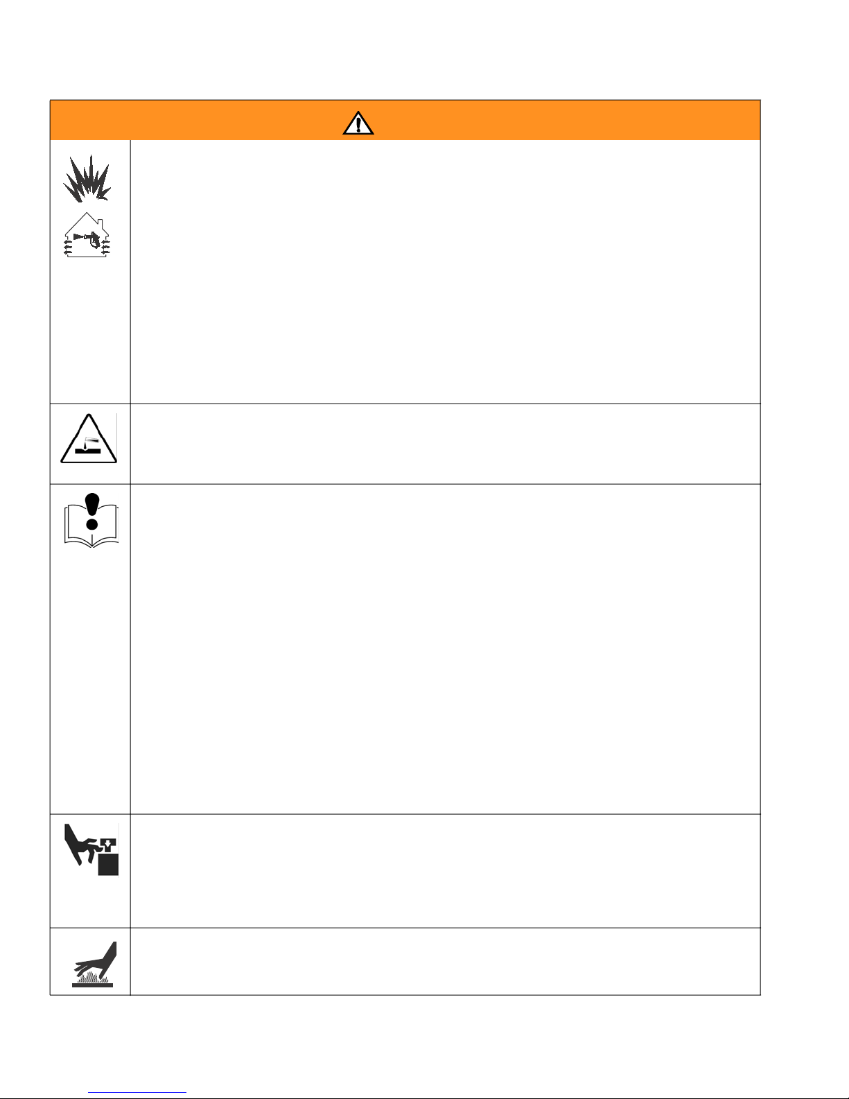
FIRE AN D EX PL OS I ON HA Z ARD
Flammable fumes, such as solvent and paint fumes, in work area can ignite or explode . To help pre-
vent fire and explosion:
• Use equipment only in well ventilated area.
• Eliminate all ignition sources; such as pilot lights, cigarettes, portable electric lamps, and plastic
drop cloths (potent ial static arc).
• Keep work area free of debris, including solvent, rags and gasoline.
• Do not plug or unplug power cords, or turn power or light switches on or off when flammable
fumes are present.
• Ground all equipm ent in work area. See Grounding instructions.
• Use only grounded hoses.
• Hold gun firm ly to side of grounded pail when trigger i ng int o pail.
• If there is static sparki ng or you feel a shock, stop operation im me dia tely. Do not use equip-
ment until you identify and correct the problem.
• Keep a fire extingu isher in the work area.
PRESSURIZED ALUMINUM PARTS HAZARD
Do not use 1,1,1-trichloroethane, methylene chloride, other halogenated hydrocarbon solvents or fluids containing such solv ents in pressurized aluminum equipment. Such use can cause serious chemical reaction and equipm ent ruptur e, and result in death, serious inj ur y, and property damage.
EQUIPMENT MISUSE HAZARD
Misuse can cause death or serious in jury.
• This equipment is for professional use only.
• Do not leave the work area while equipm ent is energized or under press ur e. Turn off all equipment and follow the Pressure Relief Procedure in this manual when equipment is not in use.
• Do not e xceed the maximum working pressure or temperature rating of the lowest rated system
component. See Technical Data in all equipment manuals.
• Use fluids and solvents that are compati ble with equipment wetted parts. See Technical Data in
all equipment manuals. Read fluid and solvent manufacturer’s warnings. For complete information about your materia l, request MSDS from distri butor or retai ler.
• Check equipment daily. Repair or replace worn or damaged parts immedi ately with genuine
Graco replace ment par t s only.
• Do not alter or modify equipment.
• Use equipment only for its intended purpose. Call your Graco distributor for information.
• Route hoses and cables away from traffic areas, sharp edges, moving parts, and hot surfaces.
• Do not kink or over bend hoses or use hoses to pull equipment.
• Keep children and animals away from work area.
• Do not operate the unit when fatigued or under the influence of drugs or alcohol.
• Comply with all applica ble safety regulations.
MOVIN G PARTS HAZARD
Moving par ts can pinch or amputate fingers and other body par t s.
• Keep clear of moving parts.
• Do not operate equipmen t with protective guar ds or covers removed.
• Pressurized equipment can start without warning. Before checking, moving, or servicing equipment, follow the Pressu re Relief Procedu re in this manual. Disconnect power or air supply.
BURN HAZARD
Equipment surfaces and fluid that’s heated can become very hot during operatio n. To avoid severe
burns, do not touch hot fluid or equipment. Wait until equipment/fluid has cooled completely.
6 313221H

Overview
Overview
The EnergyComplete Sprayer is a portable, electric-powered , 4:1 mix ratio proport ioner, for use with
EnergyComplete Air Infiltration Barrier with Flexible
Seal Technology by Owens Corning. Material s must be
self-leveling and pourable, and may be applied with
impingement mix spray guns, disposable mixer guns, or
flush-type mix manifolds.
EnergyComplete Sprayer is siphon-fed from 5 gallon
pails that can be mounted on the unit.
Severe duty, positive displacement recipr ocati ng pist on
pumps meter fluid flow to the gun for mixing and applying. When set to recirculation mode, EnergyComplete
Sprayer will circulate fluids back to the 5 gallon pails.
The EnergyComplete Sprayer includes separate thermostatically controlled heaters for each fluid. Digital displays show the temperatures of the two fluids.
An electronic processor contr ols the motor, monitors
fluid pressures, and alerts the operator if errors occur.
See STATU S Indica tor, page 9, for furt her in forma tion.
Keep Components A and
B Separate
CAUTION
To prevent cross-contamination of the equipment’s
wetted parts, never inter change c omp onent A (white
fluid) and component B (red fluid) parts.
Compatible Solvents
Use the following solvents for cleaning and flushing A
and B fluid.
A and B Fluid Co mp atible Solvent
A side (white) Water
B side (red) Owens Corning B- Sid e Cleane r
EnergyComplete Air
Infiltration Barrier
For models with a compressor: An air compressor provides and regulates air pressure for the spray gun.
EnergyComplete Sprayer has t wo recirculation speeds,
slow and fast, and an adjustable pressure output.
Slow Recirculatio n
• Slow circulation results in a higher temperature
transfer in the heater, so hoses and gun heat up
quicker.
• Good for touchup or low flow spraying, up to moderate temperature.
• Not used to circulate full pails up to temperature.
Fast Recirculation
• Use to support higher flow rates or higher temperatures by preheating the pails.
• Agitates fluid within pails, to avoid heating only the
fluid at the top of the pail.
• Use for flushing.
Pressure Adjust
Automatically maintains selected pressure output for
dispensing or spraying.
Temperature
Requirements
Material Storage
EnergyComplete Ai r Infiltration Barrier A and B fluid
should always be stored between 40-110°F
(4.4-43.3°C). The A side flui d (white) will freeze below
32°F (0°C).
If the A side fluid freezes, stir until the temperature is
between 40-110°F (4.4-43.3°C).
Application
Ensure the temperature of the EnergyComplete Air
Infiltration Barrier A and B fluid is between 70-110°F
(4.4-43.3°C).
Note: Pail heaters may be necessary.
Post Application
Ensure that the ambient air temperatur e where EnergyComplete Air Infiltration Barrier has been sprayed
remains above 40°F (4.4°C) for 24 hours after spraying.
Lower temperatures and higher humidities slow the curing process. The foam will not be resilient until it cures.
The foam will fully cure once warmer temperatures and
lower hu midit y levels return.
313221H 7
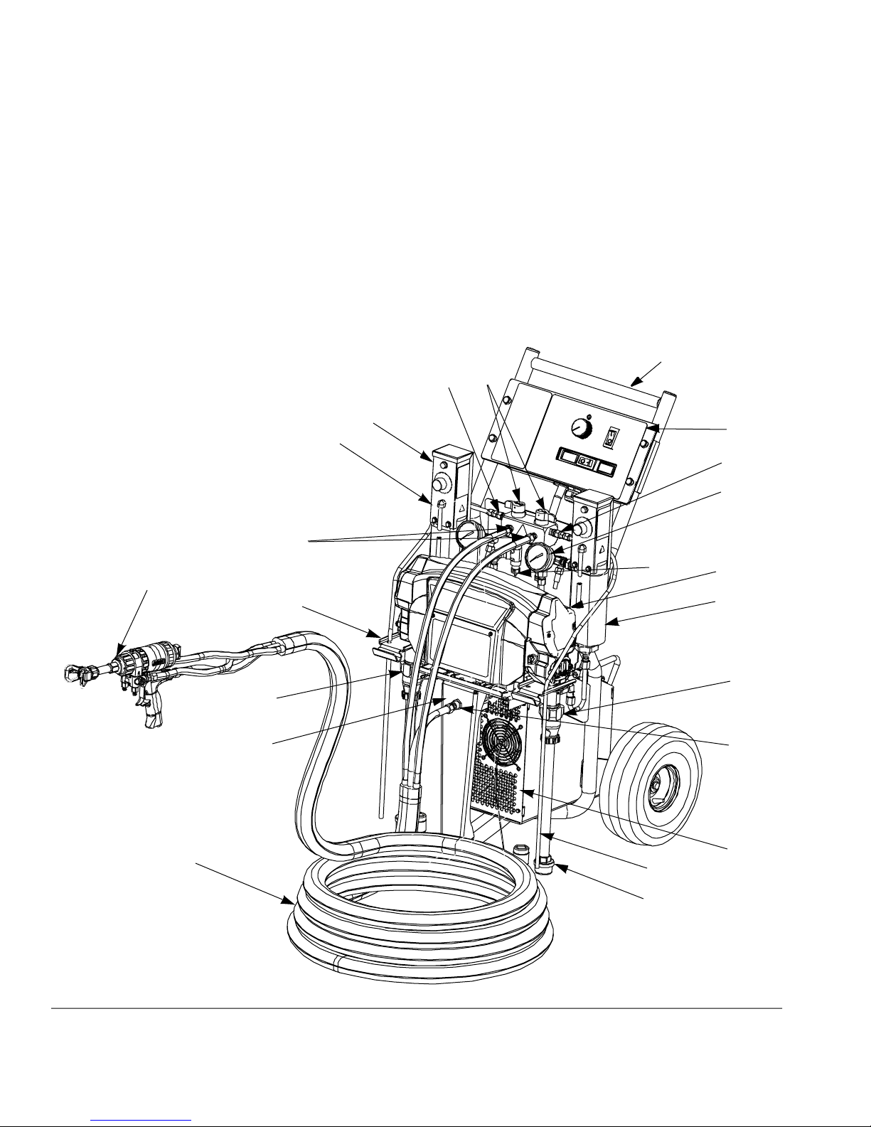
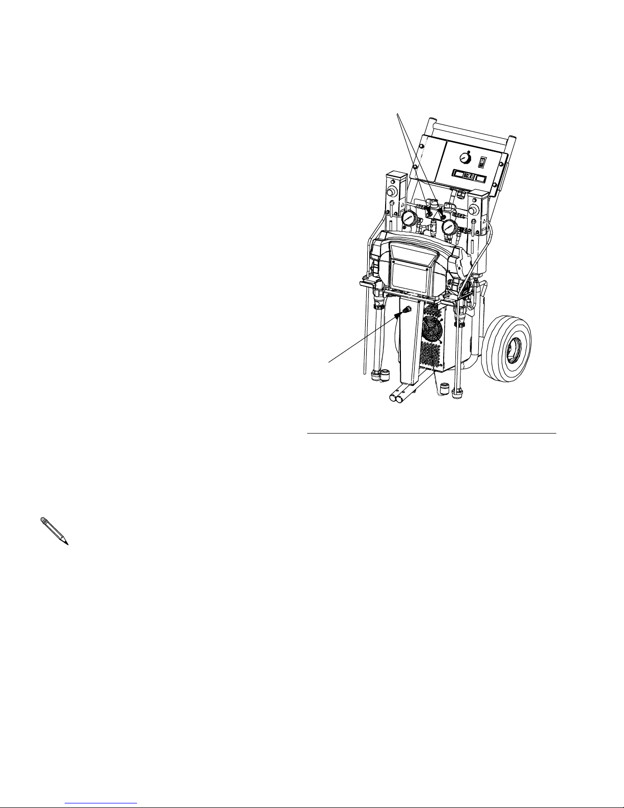
Component Identification
Key for FIG. 1
A Pump A
B Pump B
C H eater A
D H eater B
E Compressor (not supplied with all units)
F Crossbar
G Pail Mounti ng Bracket
H Flu id Press ure Gauges
J Recirc/Spray and Overpressure Rel ief Valves
K Control Panel; see FIG. 2, page 9
Component Identification
L Electri c Motor and Drive Housings
M Suction Tubes
N Reci rcul at ion Tubes
P Air Line outlet
R Outlet Hose Connections
S Recirculation Tube Connectio ns
T Flu id Temperature Sensors
U Ai r Filter/ Mois tu re Separator (behind bracket)
V Insulated Hose Bundle
W EnergyComplete Spray Gun
Heated Package 257126
W
U
F
J
S
C
H
R
T
G
A
K
S
H
L
D
B
P
V
FIG. 1: Component Identific ation, Heat ed EnergyComplete Sprayer
8 313221H
E
N
M
r_256765_313221_b_2
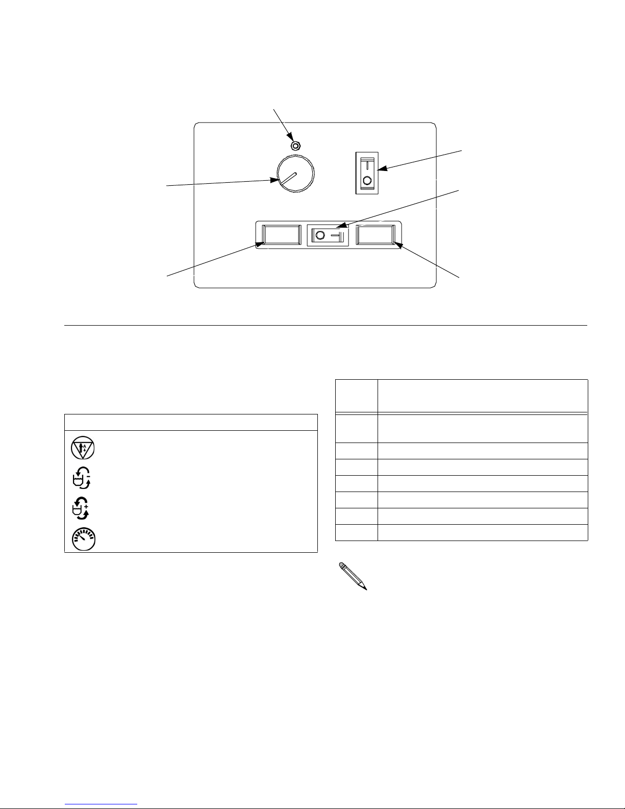
Controls and Indicators
ST
Controls and Indicators
MP
CF
TD TD
FIG. 2. Controls and Ind icator s
Motor/Pump Control Function
Knob
Use knob (CF) to select desired function.
Icon Setting Function
Stop/Park Stops motor and automati-
cally parks pumps.
Slow Recirc Slow recirculation speed.
Fast Recirc Fast reci rculati on speed.
Pressure
Adjust
Adjusts fluid pressure to
gun in spray mode.
HP
r_256765_313221_b_37
Table 1 : Status Codes
(see also the label on back of the control enclosu re)
Code
No. Code Name
1 Pressure imbalance between A and B
sides
2 Unab le to maintain pressure setpoint
3 Pressure transducer A failure
4 Pressure transducer B failure
5 Excessive current draw
6 High motor temperat u re
7 No cycle counter switch input
STATUS Indicator
• Indicator (ST) steady on: Moto r Power switch is
turned on and control board is working.
• Indicator (ST) blinking: If error occurs, STATUS indicator will blink 1 to 7 times to indicate sta tus code,
pause, then repeat. See TABLE 1 for a brief descr ip-
tion of status codes. For more detailed information
and corrective action, see page 25.
313221H 9
The default is to shut down if a status code indication occurs. Codes 1 and 2 may be set to disable automatic shutdown if desired; see page
26. The other codes are not settable.
Motor Po w er Switch /Cir cuit
Breaker
Switch (MP) turns power on to control board and function knob. The switch includes a 20 A circuit breaker.
Controls and Indicators
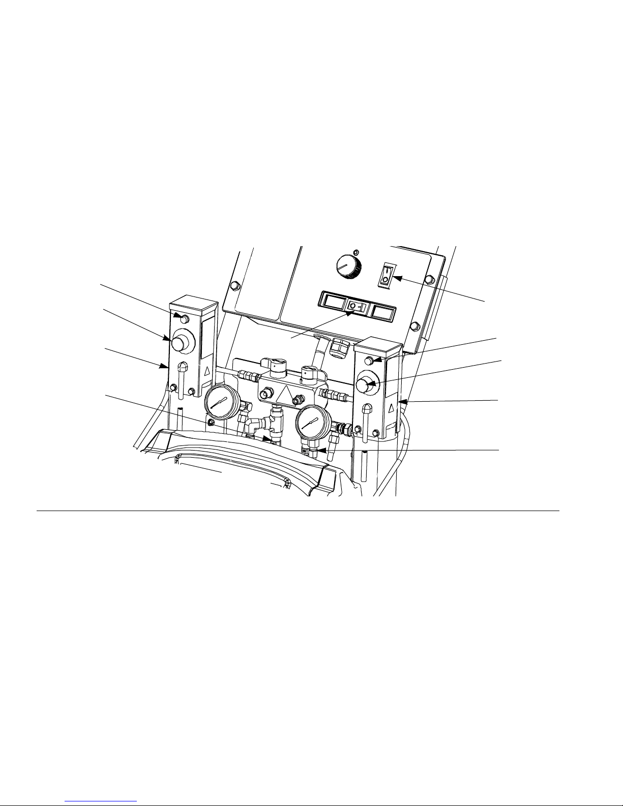
Heater Power Switch/Circuit
Breaker
See FIG. 2. Switch (HP) turns power on to heater thermostats. The switch includes a 20 A circuit breaker.
Heater Temperature Controls
See FIG. 3. Control knobs (HC) set temperature of component A and B heaters. Indicator lights (HL) turn on
when thermostat s are heating, and off when heater
reaches setpoint.
HL
HC
C
HP
Fluid Temperature Sensors and
Displays
See FIG. 2. Fluid temperature sensors (T) monitor actual
temperature of component A and B fluid going to spray
gun. T emperatures are then displayed (TD).
Unit is shipped set to °F. To change to °C, see page 37.
MP
HL
HC
T
FIG. 3. Heater Temperature Controls
D
T
r_256765_313221_b_16
10 313221H

Air Compressor Power
Switch/Circuit Breaker
Switch (CP) turns power on to compressor and regulator. The switch includes a 20 A circuit breaker.
Air Compresso r Controls
Pressure Gauge (PG) indicates set air pressur e by regulator.
Regulator (AR) sets desired air pre ssure.
CP
PG
AR
Controls and Indicators
FIG. 4
r_256765_313221_b_2
313221H 11
Setup
1. Locate EnergyComplete Sprayer
Locate EnergyComplete Sprayer on a level surface. Do
not expose EnergyComplete Sprayer to rain.
Setup
• Object being sprayed: follow your local code.
• Solvent pails used when flushing: follow your local
code. Use only metal pails, which are conductive,
placed on a grounded surface. Do not place pail on
a nonconductive surface, such as paper, plastic, or
cardboard, which interrupts grounding continuity.
2. Electrica l Requirements
Improper wiring may cause electric shock or other
serious injury if work is not performed properly. Have
a qualified electrician perform any electrical work. Be
sure your installation complies with all National, State
and Local safety and fire codes.
Connect EnergyC omplete Sprayer to the correct power
source for your model. See TABLE 2. Models with two or
three power cords must be connected to separate, dedicated circuits. See FIG. 5.
3. Grounding
• To maintain grounding continuity when flushing or
relievin g pressure, hold a metal part of spray gun
firmly to the side of a grounded metal pail, then trig-
ger gun.
The equipment must be grounded. Grounding reduces
the risk of static and electric shock by providing an
escape wire for the electrical current due to static build
up or in the event of a short circuit.
• EnergyComplete Sprayer: grounded through power
cord.
• Generator (if used): fol low y our local code. Start and
stop generator with power cord(s) disconnected.
• Spray gun: grounded through the supplied fluid
hoses, connected to a properly groun ded EnergyComplete Sprayer . Do not operate without at least
one grounded fluid hose.
12 313221H
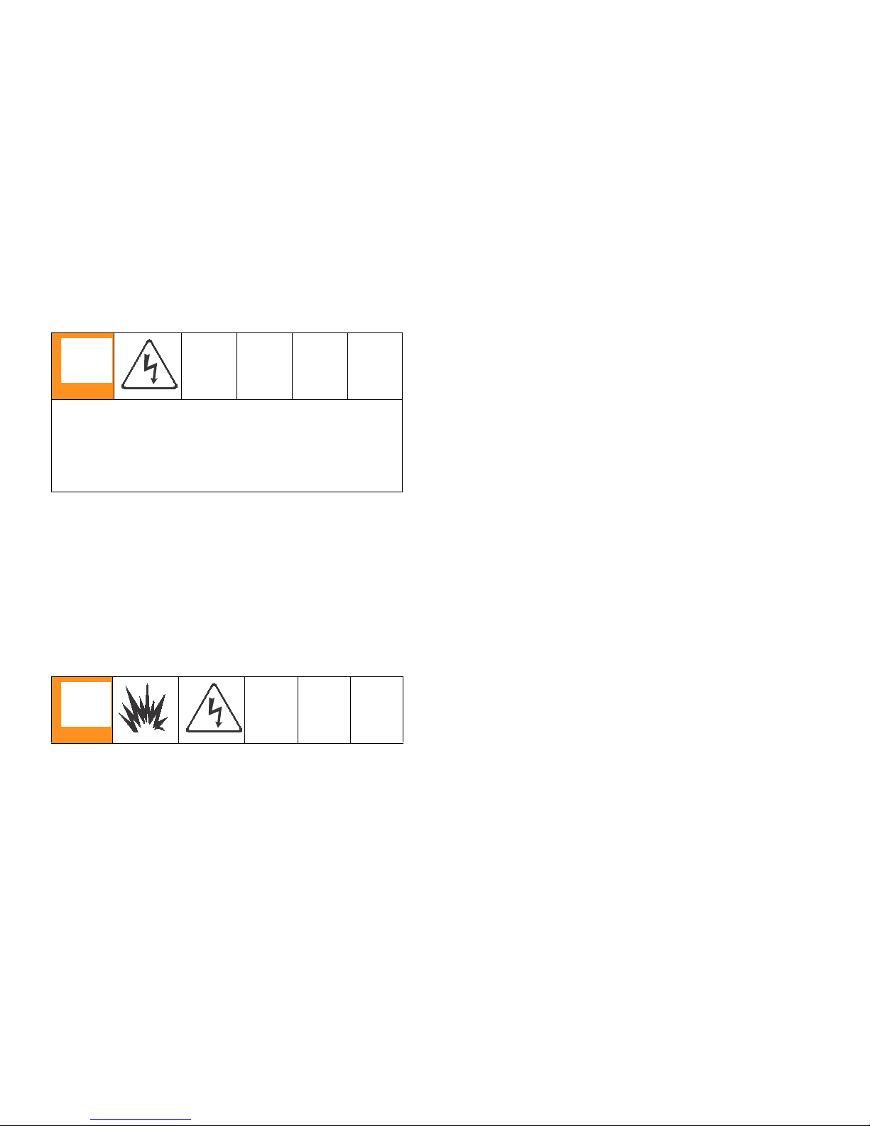
Tabl e 2: Elect r ical Requi r em ent s
Model Requi re d Power Source Power Cord Connector
256765 - 120 V, 1 phase, 50/60 Hz,
three 15 ft (4.5 m) power cords,
Three separate, dedicat ed cir cuits
rated at minimum of 15 A each
Three NEMA 5-15T
Heated
Setup
257089 - 120 V, 1 phase, 50/60 Hz,
two 15 ft (4.5 m) power cord, Heated
Two separate, dedicated circuits
rated at minimum of 15 A each
Tabl e 3: Extension Cord Requirements
Requ ir e d W ir e Size
Up to 100 ft (30 m)
AWG 12
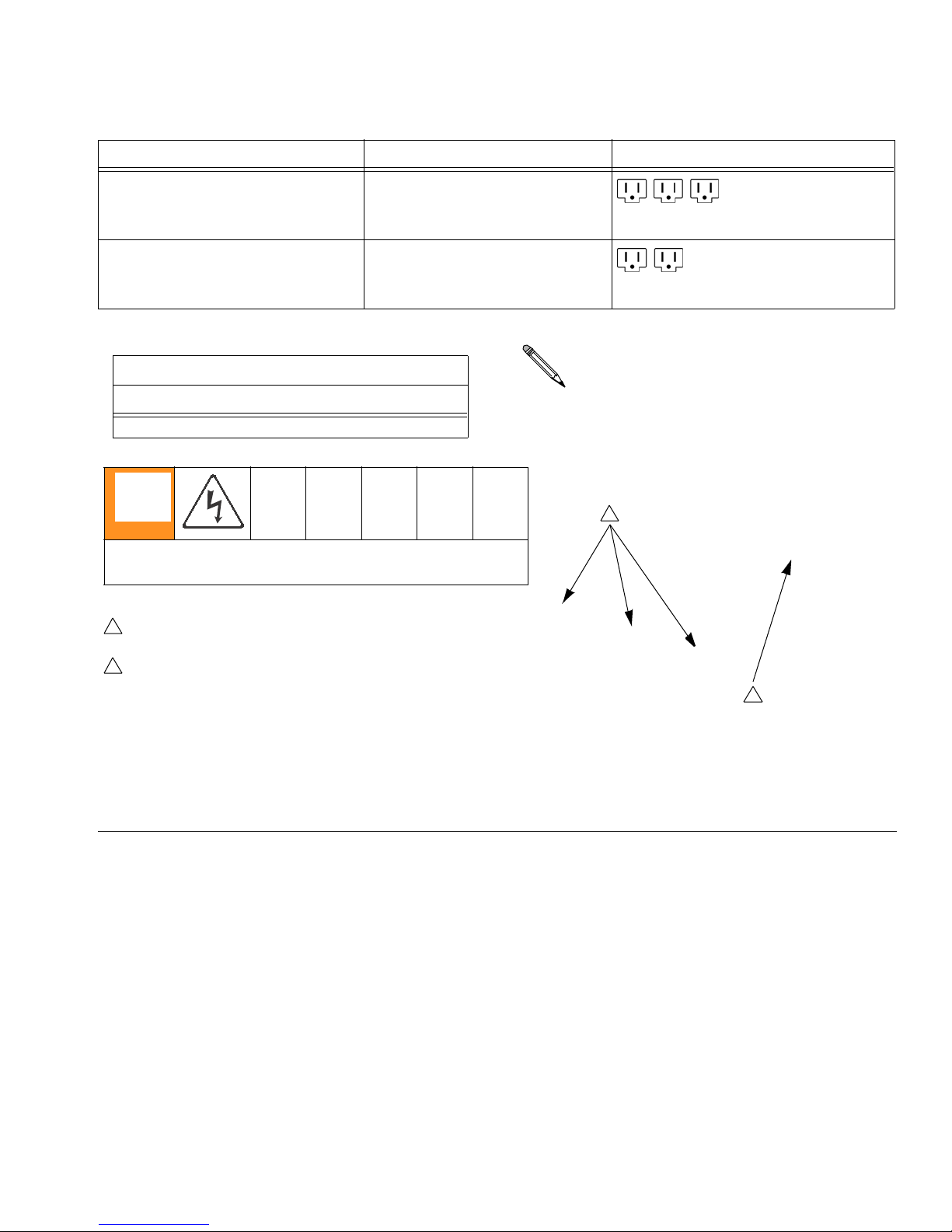
To avoid electric shock, always unplug all cords before servicing EnergyComplete Sprayer.
1
Ensure no other high amp loads are connected
while running EnergyComplete Sprayer.
2
To verify separat e c ircuits , plug in
EnergyComplete Sprayer or a worklight and
cycle breakers on and off.
Heater Power
Tw o NEMA 5-15 T
Cords must be 3-conductor grounded, rated
for your environment.
1
2
Mot o r Powe r
TI12383a
Comp res sor P ower
FIG. 5. Use Three Separate Circuits
313221H 13
4. Connect Fluid Hoses
Setup
Connect fluid supply hose to outlet hose connections (R,
FIG. 6). Fittings ar e sized to prevent connection errors.
Connect whip hose to fluid supply hose with adapter
(50) and nipple (51). Connect other end of hoses to A
and B inputs of gun.
5. Connect Gun Air Hose
Connect gun air hose to the gun air input and to the air
filter outlet (Z). If you are using more than one hose bundle, join the air hoses with the nipple (305) provided with
the hose bundle.
On heated units with Fusion guns, connect the supplied
ball valve and quick-disconnect coupler to the gun air
hose, then connect the coupler to the gun air fitting.
6. Connect main ai r supply
For sprayer s without a compressor, connect the main air
supply to the quick disconnect fitting on the air filter
behind the front brace. Air supply hose must be at least
5/16 in. (8 mm) ID up to 50 ft (15 m) or 3/8 in. (10 mm)
ID up to 100 ft (30 m).
R
Z
r_256765_313221_b_4
FIG. 6. Hose Connect ion s
7. Turn on Air Compressor
Turn on air compr essor power. Set regulator to desired
output pressure as indicated on the gauge.
Air Filter/Moistu re Sepa rator (Z) is equipped
with an automatic moisture drain.
8. Flush Before First Use
The EnergyComplete Spra y e r is te s ted wi th a plasticizer oil at the factory. Flush out the oil with a compatible
solvent before spraying. See page 23.
14 313221H
Setup
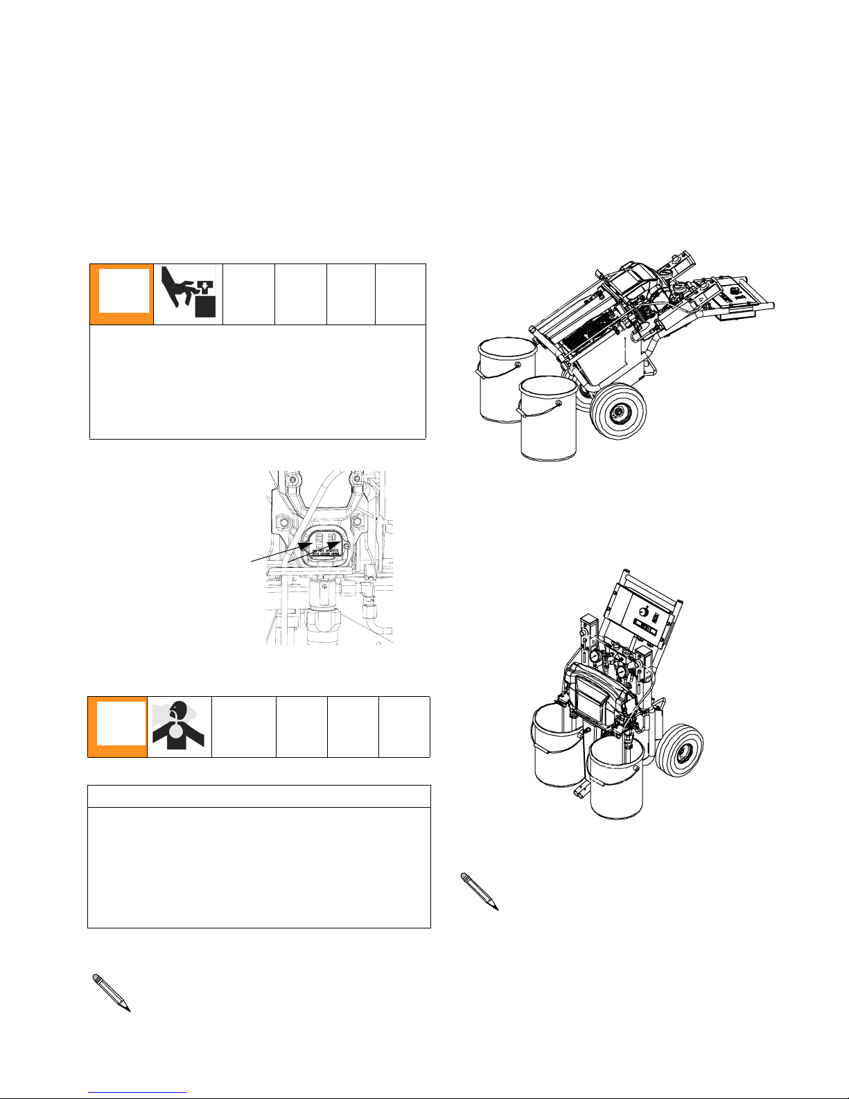
9. Fill Wet-Cups
Keep the felt washers in the pump wet-cups saturated
with Graco ISO pump oil, Part No. 217374. The lubricant
creates a barrier between the red fluid and the atmosphere.
Pump rod and connecting rod move during operation. Moving par ts can cause ser ious inj ur y suc h as
pinching or amputation. Keep hands and fingers
away from wet-cup during operation. Shut off Motor
Power before filling wet-cup.
a. Open red and white fluid pails and posi-
tion in front of suction tubes.
b. Stand behind unit and hold crossbar.
Lean unit backwards until the suction
tubes are above the supply pails.
A
B
r_256765_313221_b_12
Fill wet-cups through
slots in plate, or loosen
screws and swing plate
aside.
10. Install suction tube
NOTICE
To prevent cross-contamination of fluids and equipment parts, never interchange component A and
component B parts or containers.
Label one pail “A” and the other “B”, using the labels
provided. Always doublecheck which material you
have before placing suction tubes in pails.
c. Place suction tubes in pails.
A
B
r_256765_313221_b_17
Cut por ti on of the pail’s lid for suction tube and
assemble on pail to prevent debris from entering
pumps.
Using a drill and mixing blade, mix filled or separated mater ial s in the pail. Materi al left in the
pails overnight may need to be remixed.
313221H 15
Setup
11. Mo unt pa ils
a. Insert pail handles on mounting bracket
(G).
G
A
B
r_256765_313221_b_18
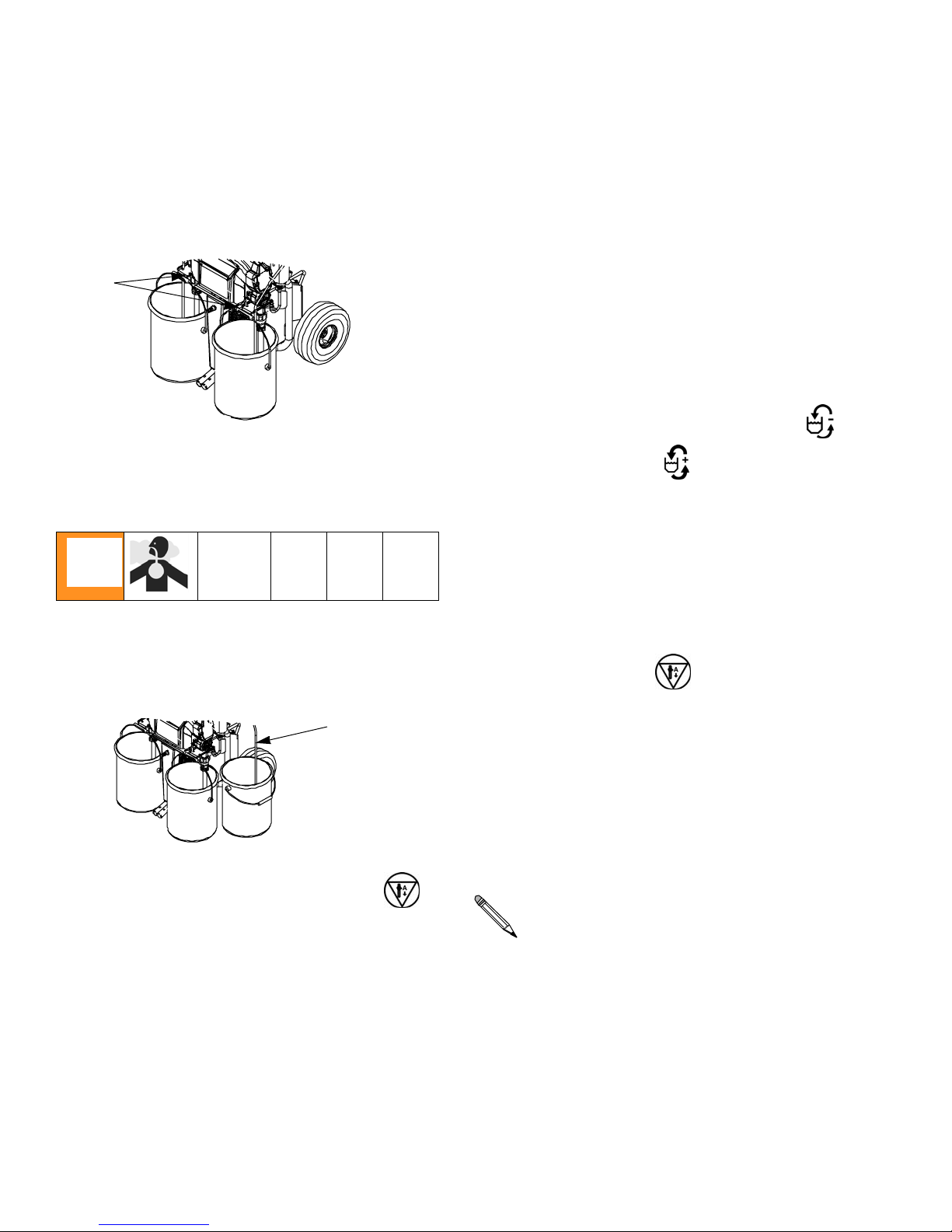
12. Purge air and flush fluid from lines
d. Turn on Motor Power.
e. Set Recirc/Spray valv es to Recirc.
f. Set function knob to Slow Recirc or
Fa st Recirc .
OR
a. Remove both recirculation tubes (N)
from the pails and secure each one in a
dedicated waste container (W).
N
A
B
W
r_256765_313221_b_19
b. Set function knob to Stop/Park .
c. Plug in power cord(s). See TABLE 2,
page 13.
g. When clean fluids exit both recirculation
tubes (P), set function knob to
Stop/Park .
h. Replace recirculat ion tubes in pails.
Preheat hoses if ambient temperature is
below 70°F (43.3°C) or continue with Startup,
page 18.
16 313221H
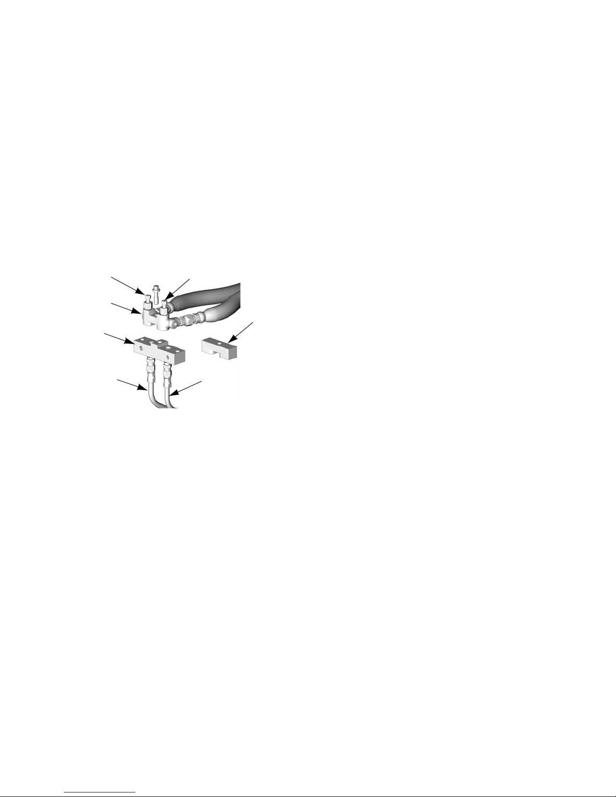
Preheat Hose s
The ambient temperature must be greater than 40°F
(4.4°C).
If the ambient temperature is below 70°F(43.3°C) it is
required to preheat the hoses.
Connect circulatio n lines (CL) to circulat ion manifold
(701). Route circulation lines (CL) back to red and white
fluid pails.
1. Remove block (702). Install circulation manifold
(701) on gun fluid manifold (GM). Open all
valves in the fluid circuit.
Setup
A
GM
701
CL CL
B
702
TI4063a
2. Perform Startup, page 18.
3. Cl ose flu id valves A and B. Remove circulation
manifold (701) from gun fluid manifold (GM).
Attach block (702) to circulation manifold to prevent air from reacting with EnergyComplete Ai r
Infiltration Barrier.
313221H 17

Startup
Equipment surfaces can become very hot. To avoid
severe burns:
• Do not operate EnergyComplete Spra ye r wit hout
all covers and shrouds in place.
• Do not touch hot fluid or equipment.
• Allow equipment to cool completel y before touching it.
• Wear gloves if fluid temperatu re exceeds 110°F
(43°C).
1. Perform Setup, pages 12- 16.
Startup
2. Set function knob to Slow Recirc or Fast
Recirc .
OR
3. Turn on Heater Power.
4. Temporari ly set heater control knobs to maxi-
mum setting.
5. Ci rculate through heaters until temperature
readouts display desired temperature.
6. Adj ust heat er control knobs as neces sar y for a
stable spray temperature.
18 313221H
 Loading...