

Page 1

Instructions–Parts List
TI1377A
EnDure™ Automatic
Dispense Valves
Air-operated dispense valves used for sealant and adhesive materials.
3500 psi (24.10 MPa, 241 bar) Maximum Dynamic Discharge Fluid Working Outlet Pressure
5000 psi (34.5 MPa, 345 bar) Maximum Static Working Pressure
120 psi (.83 MPa, 8.3 bar) Maximum Air Pressure
Important Safety Instructions
Read all warnings and instructions in this manual.
Save these instructions.
309376L
EN
06540A
Page 2

Table of Contents
Table of Contents . . . . . . . . . . . . . . . . . . . . . . . . . . 2
Models . . . . . . . . . . . . . . . . . . . . . . . . . . . . . . . . . . . 3
Warnings . . . . . . . . . . . . . . . . . . . . . . . . . . . . . . . . . 4
Installation . . . . . . . . . . . . . . . . . . . . . . . . . . . . . . . . 7
Maintenance . . . . . . . . . . . . . . . . . . . . . . . . . . . . . . 11
Troubleshooting . . . . . . . . . . . . . . . . . . . . . . . . . . 13
Service . . . . . . . . . . . . . . . . . . . . . . . . . . . . . . . . . . 14
Parts . . . . . . . . . . . . . . . . . . . . . . . . . . . . . . . . . . . . 20
Accessories . . . . . . . . . . . . . . . . . . . . . . . . . . . . . . 30
Dimensions . . . . . . . . . . . . . . . . . . . . . . . . . . . . . . 32
Technical Data . . . . . . . . . . . . . . . . . . . . . . . . . . . . 34
Wiring Diagram . . . . . . . . . . . . . . . . . . . . . . . . . . . 35
Graco Standard Warranty . . . . . . . . . . . . . . . . . . . 36
2 309376L
Page 3

Models
Basic
Valve
Part No.
244535 244910 Valve, ambient or water
244907 244908 Valve, 120 Volt E-Heat
244937 244951 Valve, 230 Volt E-Heat
Complete
Valve
Part No.
244961 Valve, 120 Volt E-Heat
244962 Valve, 230 Volt E-Heat
244909 Valve, 230 Volt E-Heat
297261 Complete Valve, 240 Volt
245184 Valve, 120 Volt E-Heat
Description
(Replaces ...)
conditioned. Replaces
C27340 hard seat and
918512 soft seat snuff-back,
if application is under 95 C
(200 F).
Replaces valve 194485.
Any heated PrecisionFlo
before XL (July 2001) if
application is under 95 C
(200 F).
Replaces 243694 hard seat
and 243696 soft seat snuffback valves. Any Therm-OFlow Plus (after July 2000)
if application is under 95 C
(200 F).
Replaces C34068 hard
seat, 918483 soft seat
snuff-back, any
Therm-O-Flow before
Therm-O-Flow Plus (July
2000) if application is 95 C
(200 F) to 204 C (400 F).
Replaces 243694 hard seat
and 243696 soft seat snuffback valves. Any Therm-OFlow Plus (after July 2000) if
application is 95 C (200 F)
to 204 C (400 F).
E– Heat; Swirl Equipped
Replaces valve 243695
hard seat with 1/2” npt (m)
outlet. Any Therm-O-Flow
before Therm-O-Flow Plus
(July 2000) if application is
95 C (200 F) to 204 C (400
F).
Replaces C34079 hard seat
with 1/2” npt (m) outlet. Any
Therm-O-Flow Plus (after
July 2000) if application is
95 C (200 F) to 204 C (400
F).
Maximum
Fluid
Heater Voltage
Temperature
Rating C (F)
95 C (200 F) Nonpowered
95 C (200 F) 120 VAC
95 C (200 F) 230 VAC
204 C (400 F) 120 VAC
204 C (400 F) 230 VAC
204 C (400 F) 240 VAC
204 C (400 F) 230 VAC
204 C (400 F) 120 VAC
Pin Connector Wattage
ambient or water
circulation for
temperature
conditioning
6 Pin round
8 Pin square
6 Pin round
8 Pin square
8 Pin square
8 Pin square
6 Pin round
0
150
200
150
200
200
150
200
Valve Outlet
Connection
5/8–18 male
thread.
Retainer nut
with 1/8 npt(f)
5/8-18 male
thread.
Retainer nut
with 1/8 npt(f)
5/8-18 male
thread.
Retainer nut
with 1/8 npt(f)
5/8-18 male
thread.
Retainer nut
with 1/8 npt(f)
5/8-18 male
thread.
Retainer nut
with 1/8 npt(f)
5/8-18 male
thread with
swirl adapter
1/2 npt (m) 23
1/2 npt (m) 27
Parts
Page
29
27
23
27
23
309376L 3
Page 4

Warnings
The following warnings are for the safe setup, use, grounding, maintenance, and repair of this equipment. The
exclamation point symbol alerts you to a general warning and the hazard symbols refer to procedure-specific risks.
Refer back to these warnings. Additional, product-specific warnings may be found throughout the body of this manual
where applicable.
WARNING
EQUIPMENT MISUSE HAZARD
Equipment misuse can cause the equipment to rupture, malfunction, or start unexpectedly and result in serious
injury.
INSTRUCTIONS
• This equipment is for professional use only.
• Read all instruction manuals, warnings, tags, and labels before operating the equipment.
• Use the equipment only for its intended purpose. If you are uncertain, call your Graco distributor.
• Do not alter or modify this equipment. Use only genuine Graco parts and accessories.
• Check the equipment daily. Repair or replace worn or damaged parts immediately.
• Do not exceed the maximum air working pressure of 1 MPa (8.3 bar, 120 psi) to the applicator.
• Do not exceed the maximum fluid working pressure of 24 MPa (241 bar, 3500 psi) to the applicator or manifold.
• Never exceed the recommended working pressure or the maximum air inlet pressure stated on your pump or in
the Technical Data on page 34.
• Be sure that all spray/dispensing equipment and accessories are rated to withstand the maxi- mum working
pressure of the pump. Do not exceed the maximum working pressure of any component or accessory used in the
system.
• Route hoses away from traffic areas, sharp edges, moving parts, and hot surfaces.
• Do not expose Graco standard hoses to temperatures above 180°F (82°C) or below -40°F (-40°C). Do not expose
Graco electrically heated hoses to temperatures above 400°F (222°C) or below -40°F (-40°C).
• Do not use the hoses to pull the equipment.
• Use only fluids and solvents that are compatible with the equipment wetted parts. See the Technical Data sections
of all the equipment manuals. Read the fluid manufacturer's warnings.
• Always wear protective eyewear, gloves, clothing, and respirator as recommended by the fluid and solvent
manufacturers.
• Wear hearing protection when operating this equipment.
• Comply with all applicable local, state and national fire, electrical and other safety regulations.
4 309376L
Page 5

WARNING
HOT SURFACE AND FLUID HAZARD
Heated fluid can cause severe burns and can cause equipment surfaces to become very hot.
• Wear protective gloves and clothing when operating this equipment in a heated system.
• Do not touch the metal heat sink when the surface is hot.
• Allow the equipment to cool thoroughly before servicing.
Some heated systems are designed to dispense Polyurethane (PUR) heated materials. PUR systems are supplied
with ventilation hoods, and require proper ventilation and specially designed system components.
SKIN INJECTION HAZARD
Spray from the applicator, hose leaks, or ruptured components can inject fluid into your body and cause extremely
serious injury, including the need for amputation. Fluid splashed in the eyes or on the skin can also cause serious
injury.
• Fluid injected into the skin might look like just a cut, but it is a serious injury. Get immediate surgical treatment.
• Do not point the applicator at anyone or at any part of the body.
• Do not put hand or fingers over the front of the applicator.
• Do not stop or deflect fluid leaks with your hand, body, glove, or rag.
• Follow the Pressure Relief Procedure on page 14 whenever you are instructed to: relieve pressure; stop
dispensing; clean, check, or service the equipment; or install or clean a tip or nozzle.
• Tighten all the fluid connections before operating the equipment.
• Check the hoses, tubes, and couplings daily. Replace worn, damaged, or loose parts immediately. Permanently
coupled hoses cannot be repaired; replace the entire hose.
• ALWAYS wear eye protection and protective clothing when installing, operating, or servicing this dispensing
equipment.
• Do not remove or modify any part of the applicator; this can cause a malfunction and result in serious bodily injury.
• Use extreme caution when cleaning or changing tips. If the tip clogs while applying material, ALWAYS follow the
Pressure Relief Procedure on page 14, then remove the tip to clean it.
• NEVER wipe off build-up around the tip or air cap until pressure is fully relieved.
309376L 5
Page 6

WARNING
FIRE, EXPLOSION, AND ELECTRIC SHOCK HAZARD
Improper grounding, poor air ventilation, open flames, or sparks can cause a hazardous condition and result in fire or
explosion and serious injury.
• Ground the equipment and the object being sprayed. The Heated Automatic Dispense Valve is grounded to truth
earth ground inside the electrical control panel. See Grounding on page 9.
• Ground the equipment and the object being sprayed, and all other electrically conductive objects in the dispense
area. Proper grounding dissipates static electricity generated in the equipment. See Grounding on page 9.
• Do not use this equipment with flammable liquids.
• Keep the dispense area free of debris, including solvent, rags, and gasoline.
• If there is any static sparking or you feel an electric shock while using the equipment, stop dispensing
immediately. Do not use the equipment until you have identified and corrected the problem.
• Make sure all electrical work is performed by a qualified electrician only.
• Have any checks, installation, or service to electrical equipment performed by a qualified electrician only.
• Make sure all electrical equipment is installed and operated in compliance with applicable codes.
• Make sure power is disconnected when servicing and repairing equipment.
• Before operating the equipment, extinguish all open flames or pilot lights in the dispense area.
• Do not smoke in the dispensing area.
• Keep liquids away from the electrical components
• Disconnect electrical power at the main switch before servicing the equipment.
• Never exceed maximum wattage of the supply unit.
TOXIC FLUID HAZARD
Hazardous fluids or toxic fumes can cause serious injury or death if splashed in the eyes or on the skin, swallowed,
or inhaled.
• Provide fresh air ventilation to avoid the buildup of vapors from the fluid being dispensed.
• Know the specific hazards of the fluid you are using.
• Store hazardous fluid in an approved container. Dispose of hazardous fluid according to all local, state and national
guidelines.
• Always wear protective eyewear, gloves, clothing and respirator as recommended by the fluid and solvent
manufacturer.
• Avoid exposure to heated material fumes.
6 309376L
Page 7

Installation
TI1377A
Fluid
Inlet
Water
Circulation
Ports
Install the automatic applicator as follows:
• mount the automatic dispense valve
• attach dispense tip or nozzle
• connect the air lines
• connect material hose
• if heated, connect the electrical cable
• if temperature conditioned, connect the water
circulation
• make sure the automatic dispense valve is
grounded
Mount the Automatic Dispense Valve
Mount the automatic dispense valve to the mounting
bracket on a stationary support or robotic arm (Fig. 1),
using two M6x1.0 socket head screws and two flat
washers. If your application is heated, be sure to
position the insulation block between the dispense valve
and the mounting bracket, (Fig. 2). Refer to the
dimensions on page 32.
Mounting
Holes
Ambient or temperature conditioned model shown
Fig. 1 ______________________________________
309376L 7
Page 8

Installation
Open and Close
ports are on this
side.
Fluid Inlet
Connect Air Lines to Dispense Valve
CAUTION
Only use air fittings that are rated at a temperature
equal to or higher than the operating temperature
of your fluid dispensing system. Lower rated air
fittings could melt and cause damage to the
automatic dispense valve.
These valves are air to open and air to close with a
spring to bias them closed. Use a 4-way exhausting
solenoid to operate these valves.
Be sure to connect the appropriate air lines to the
appropriate ports (Fig. 2), and securely connect air lines
to dispense valve air ports. See page 32.
Connect Material Hose to Dispense Valve
Securely connect the material hose to the dispense
valve material inlet port. See Fig. 2.
Connect Electrical Cable to Electrically
Heated Dispense Valves
Connect electrical cable plug from your Therm-O-Flow,
Therm-O-Flow Plus, or PrecisionFlo hose or control.
A six-pin round connector is used on 120 volt valves and
an eight-pin square connector is used on 240 volt
valves.
Temperature
insulation
spacer
240 volt heated model shown
Fig. 2 ______________________________________________________________________________________
8 309376L
Page 9

Installation
67
5412
3
TI0305
240 Volt models
Grounding
WARNING
FIRE, EXPLOSION, AND ELECTRIC
SHOCK HAZARD
To reduce the risk of fire, explosion, or
electric shock:
• The power source conduit is not an
adequate ground for the system.
The unit must be grounded to either the
building ground or a true earth ground.
• A qualified electrician must complete all
grounding and wiring connections and
check the resistance.
Ground lead coming
from contact 8 is
fastened to the
valve body
• Refer to your local code for the requirements for a
"true earth ground" in your area.
• Also read and follow the warnings on page 6.
Electrically Heated Models.
Ground the automatic dispense valve:
1. Connect the connector from a heated hose to the
receptacle on the dispense valve.
Ground lead
coming from pin
E is fastened to
the valve body.
Heater
cartridge
Fig. 3 ______________________________________
120 Volt models
RTD
sensor
Fig. 4_______________________________________
2. Connect the electrical cable to the electrical control
panel.
3. Verify that socket contact E on six pin models
(see Fig. 5) or contact eight on eight pin models
(see Fig. 4), inside control panel receptacle,
is connected to true earth ground.
See page 35 for schematics.
Snuff-Back
Snuff-back is created when the needle is pulled back
through a restrictive ring before it closes against the
carbide seat.
For maximum snuff-back, leave the ring in place.
For maximum flow with less snuff-back, remove the ring.
For additional snuff-back, use a quick exhaust valve
(104661) on the "open" air port.
Nozzle selection and gun movement also effect fluid
cut-off characteristics.
309376L 9
Page 10

Installation
Connecting the Electrical Cable from a
Therm-O-Flow Plus Heated Hose
1. Wrap the hose cable around the hose one time.
Connect the electrical cable from the hose to the
valve cable; lock the metal clip on the top of the
connector. See Fig. 5.
2. Place the flat side of the cable connection against
the hose, making sure the metal clip faces away
from the hose. This will prevent damage to the hose
from the clip rubbing against it. See Fig. 6.
3. Secure the cable connector to the hose with heavy
tape or Velcro straps. For installations where the
dispense valve is moving, it is recommended that
the connector be wrapped with the Graco accessory
Velcro wrap (198422) and 2 Velcro straps (198442)
as shown in Fig. 7.
Fig. 5 ______________________________________
Fig. 6 ______________________________________
Fig. 7 ______________________________________
10 309376L
Page 11

Maintenance
The following tables list recommended maintenance procedures and frequencies. The maintenance is divided
between mechanical and electrical tasks. A typical application is a valve mounted on a robot dispensing a
moderately abrasive sealant.
Mechanical
Task
Inspect for leaks
Check hoses for wear*
Check/tighten fluid connections*
Check/tighten air connections*
Lube packings
Rebuild dispense valve
Replace valve
* Assumes movement from automation.
Electrical
Task
Check cables for wear
Verify cable connections
Verify resistance of electric heaters
Verify resistance of RTD sensors
Daily
Daily
Weekly
Weekly
Monthly or
30,000 cycles
Monthly
3-6 months or
125,000 cycles
6 Months
6-12 months or
250,000 cycles
18-24 months or
500,000 cycles
36-48 months or
1,000,000 cycles
6-8 years or
2,000,000 cycles
12 Months
Packing Lubrication
This valve has a primary seal, a pressurized grease
area, and a secondary seal. The key to long seal life is
that the secondary seal only has to seal grease.
When dispensing filled materials this grease should be
refreshed once a month.
309376L 11
1. Remove one of the zerk grease fittings (23).
2. Using a grease gun, pump a high quality grease like
#115982 (high temperature moisture free) into the
remaining zerk fitting until fresh grease comes out
the other side.
3. Replace the grease fittings and give the valve one
more shot of grease to pressurize the cavity.
Page 12

Maintenance
Factors affecting valve life
The maintenance tables should be used as a guideline
for frequency of maintenance tasks. Additional factors
that affect valve life include the following:
• Process fluid - Abrasive or fiber filled fluids are
much harder on seals, shafts, and seats than
non-abrasive fluids such as oil.
• Pressure drop across the valve seat - As the
valve opens or closes, the fluid is accelerated to a
high velocity at the needle/seat contact area. The
rate of wear at the valve will be much greater at
3000 psi than at 1000 psi. Changing nozzle or tip
size can have a substantial affect on wear.
• Number of cycles - This has a much greater affect
on valve wear than number of gallons. If you can do
the same job with fewer on/off cycles, the valve will
last longer.
• Speed of actuation - Snapping the valve open and
closed quickly will give longer needle and seat life.
Avoid long air tube runs after the solenoid, or use
quick exhaust valves (104661) on the dispense
valve.
• Air pressure - This is what provides the force to
hold the hardened SST needle against the carbide
seat to seal against fluid pressure. Any leakage on
these hard parts, at high pressure, will quickly
"worm-hole" the parts and cause the valve to fail.
This valve has been designed with two air pistons to
give it an exceptionally high, 68:1 advantage of air
pressure to fluid pressure. This means that you can
reliably operate at 60 psi of air, even with 4000 psi
of downstream pressure.
12 309376L
Page 13
Troubleshooting
Some solutions require disassembling the automatic dispense valve. Always relieve system pressure before performing these procedures.
WARNING
To reduce the risk of serious injury whenever you are instructed to relieve pressure, always follow the
Pressure Relief Procedure (page 14).
See PARTS section for the parts that need to be serviced.
Problem Cause(s) Solution(s)
Air leaks from automatic
dispense valve
Material leaks from front of
automatic dispense valve
Material leaks from automatic
dispense valve body
Automatic dispense valve does
not shut off
Automatic dispense valve does
not shut off
Automatic dispense valve does
not shut off
Automatic dispense valve does
not heat material
Automatic dispense valve will
not open
Loose air connections Check air connections.
Worn o-rings Replace o-rings in cylinder.
Seal, needle, or seat is worn Replace seat seals (12 & 26), needle (7),
and seat (13).
Obstruction inside dispense valve Remove nose piece (6). Check and
replace if necessary, seals (12 & 26),
needle (7), and seat (13).
Worn needle Check and replace needle (7), if
necessary. If replacing needle, you must
reverse or replace seat (13).
Worn seat (Base seal models) Check and replace or reverse seat (13) if
necessary. Replace needle (7) with seat
(13).
Seal not installed correctly Check seals (15 & 16) and replace if
Seal is worn
Loose air connections Check air connections.
Worn needle-seal interface Replace rod seal (12 & 26), needle (7),
Broken retaining ring (10) or debris in air
cylinder.
Spring broken or not installed correctly Disassemble dispense valve. Check
Loose heater wires Check and reconnect wire connections.
Loose sensor wires Check and reconnect wire connections.
Heater unit failed Replace heater.
Sensor failed Replace sensor.
Temperature controller failed Replace temperature controller.
No power to heating circuitry Apply power to heating circuitry.
Fluid pressure in outlet line greater than
24.1 MPa (241 bar, 3500 psi)
Air cylinder pressure too low Increase air pressure
necessary.
and seat (13).
Disassemble dispense valve. Check and
replace, if necessary, retaining ring (10)
and o-rings (17, 18, 19 and 21).
spring (24) and replace, if necessary.
Reduce outlet restrictions
Reduce fluid pressure
309376L 13
Page 14
Service
Pressure Relief Procedure
WARNING
HOT SURFACE AND FLUID HAZARD
The material and equipment will be hot!
To reduce risk of injury, wear eye
protection, gloves and protective clothing
when installing, operating, or servicing this
dispensing system.
SKIN INJECTION HAZARD
The system pressure must be manually
relieved to prevent the system from
starting or spraying accidentally. Fluid
under high pressure can be injected
through the skin and cause serious injury.
To reduce the risk of an injury from
injection, splashing fluid, or moving parts,
follow the Pressure Relief Procedure
whenever you:
• are instructed to relieve the pressure
• stop spraying/dispensing
• install or clean the nozzle
• check or service any of the system
equipment
This procedure describes how to relieve pressure from
the automatic dispense valve. See your supply unit or
system documentation for instructions on relieving
pressure for the entire dispensing system. Use this
procedure whenever you shut off the dispense valve
and before checking or adjusting any part of the system,
to reduce the risk of serious injury.
1. Shut off the material supply.
2. If heated, shut off electrical power to the automatic
dispense valve.
3. Close all self bleeding air supply valves for supply
unit.
4. Have a container ready to catch the drainage, then
bleed off material pressure by actuating the
dispense valve.
5. Shut off air supply to valve.
NOTE: If you suspect that the nozzle or hose is
completely clogged, or that pressure has not
been fully relieved after following the steps
above, very slowly loosen the tip retaining nut
or hose end coupling to relieve pressure
gradually, then loosen completely. Then clear
the tip/nozzle or hose.
PRESSURIZED FLUID HAZARD
High pressures can cause serious
personal injury. Be sure to open the
dispense valve during system heat-up
to alleviate pressure which might occur in
the system due to material expansion.
14 309376L
Page 15
Service
Prepare to Service Automatic Dispense
Valve
If the unit is hot, determine whether or not you can
service the unit after it has cooled down. Some
materials, like polyurethanes, may cure permanently
when cooled and exposed to air, preventing you from
disassembling the dispense valve. If you are working
with such a material, service the unit while the material
is at a temperature where the material is soft enough to
work with. If the material can be reheated at a later time,
you can service the unit after it has cooled, reheating
the material as necessary.
Perform this procedure before servicing the automatic
dispense valve.
1. Relieve the system pressure.
WARNING
To reduce the risk of serious injury, whenever you
are instructed to relieve pressure, always follow the
Pressure Relief Procedure (page 14).
4. Remove power from the automatic dispense valve.
WARNING
HOT SURFACE AND FLUID HAZARD
The material and equipment will be hot!
To reduce risk of injury, wear eye
protection, gloves and protective clothing
when servicing this dispensing system
component.
5. If the material in the dispense valve can be
reheated, wait for the dispense valve to cool
thoroughly before servicing it.
If the material in the dispense valve cures
permanently when cooled and/or exposed to air,
service the unit while the material is at a
temperature where the material is soft enough to
work with.
2. Make sure material flow has been shut off.
3. Make sure system air has been shut off.
309376L 15
Page 16
Service
TI1378A
Service the Automatic Dispense Valve
The dispense valves can be serviced or replaced
without disconnecting the fluid hose or temperature
control cables or tubes.
Disconnect Automatic Dispense Valve from its
Inlet Manifold
Remove the automatic dispense valve from its mounting
bracket.
1. Perform the procedures in Prepare to Service
Automatic Dispense Valve on page 15.
WARNING
HOT SURFACE AND FLUID HAZARD
The material and equipment will be hot!
To reduce risk of injury, wear eye
protection, gloves and protective clothing
when servicing this dispensing system
component.
2. Disconnect air lines from dispense valve air ports.
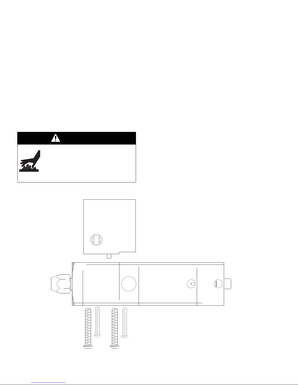
3. Remove 4 M-6 socket head screws that connect the
valve body to the inlet manifold. (see Fig. 8.)
4. Pull the valve body straight away from the inlet
manifold.
Reconnect Automatic Dispense Valve to Mounting
Bracket
1. Install new o-ring on fluid passage and water
passages if used.
2. Line up valve body with locating pins and heater
and sensor if used.
3. Push valve straight on to pins. Torque retaining
screws evenly to 50-60 in/lb.
4. Reconnect air lines to dispense valve air ports.
Fig. 8 ______________________________________________________________________________________
16 309376L
Page 17

Service
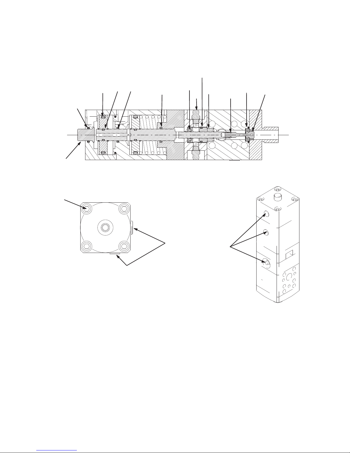
Valve models 244535, 244907, and 244937
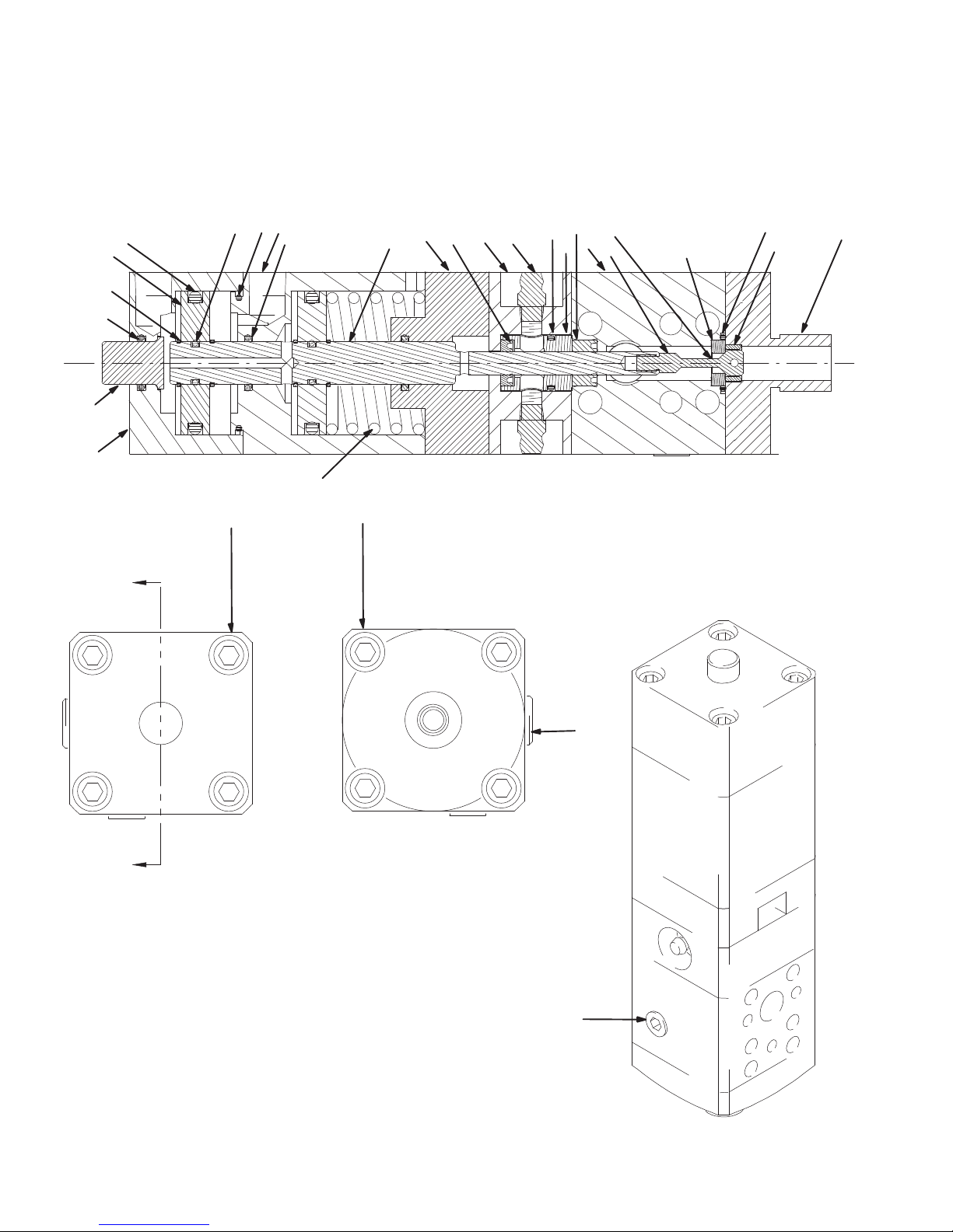
NOTE: See parts drawing on page 20 for parts
referenced in parentheses ( ).
Disassemble Automatic Dispense Valve
NOTE: The fluid section and the air section can be
serviced independently.
Fluid Section
1. Remove 4 screws (22) and pull the nose piece (6)
straight off.
2. Insert a 3/32 punch or an allen wrench through the
hole in the head of the needle (7) and unscrew from
shaft (8). Another punch can be used through the
hole in shaft (8) to keep it from turning.
3. Remove seat (13) and gasket (12).
4. Pull fluid housing (5) and grease bearing housing
(4) from the shaft.
Air Section
1. Remove 4 screws (22) from top of valve. Pull top air
cylinder housing (1) straight off.
2. Remove the first retaining ring (10), piston (9), and
second retaining ring (10).
NOTE: Use only the new retaining rings provided in
repair kit when reassembling air section of valve.
3. Pull lower air cylinder housing (2) straight away from
housing (3)
4. Remove shaft (8) if fluid section has been
disassembled.
309376L 17
Page 18

Service
Assembly of Automatic Dispense Valve
Valve models 244535, 244907, and 244937
NOTE: See parts drawing on page 20 for parts
referenced in parentheses ( ). See service drawing on
page 19 for references to steps in this procedure [x].
Air Section
1. Lubricate all seals and sliding parts with a high
temperature, moisture free grease such as
#115982 grease cartridge (ordered separately).
2. Assemble o-rings (17), (19), and (21) into or onto
their respective parts as shown. Install o-ring (18)
only to housing (3).
3. Insert shaft (8), (small end first) into housing (3).
NOTE: • Do not overextend retaining ring (10) during
installation and repair.
• Make sure to assemble retaining ring
longitudinally down the shaft diameter.
• Do not stretch the ring around the diameter.
• Use only the new retaining rings provided in
repair kit when reassembling air section of
valve.
4. Assemble the lowest retaining ring (10 ) on the
shaft. Add o-ring (18) onto the shaft, then add spring
(24), a piston (9), and the next retaining ring (10).
5. Slide housing (3) straight down over shaft (8) with
pieces aligned as shown.
6. Add next retaining ring (10), o-ring (18), piston (9),
and last retaining ring (10).
7. Insert button (33) into housing (1) and push
assembly down over the piston and shaft.
Fluid Section
10. Lubricate all seals and sliding parts with a high
temperature, moisture free grease such as
#115982 grease cartridge (ordered separately).
11. Carefully insert “U” cup (15) into bearing (11) with
the open end of the seal facing into the bearing.
Install o-ring (21) on the outside groove of the
bearing.
12. Insert the bearing, “U” cup end first, into the grease
housing (4). Push this assembly onto shaft (8) while
holding bearing (11) into housing (4).
13. Carefully insert “U” cup (16), lips first, into the
appropriate end of housing (5). Push this assembly
onto shaft (8), up against housings (3) and (4).
14. Place the valve in a vice such that it is pushing
button (33) to compress the spring.
15. Place the clear plastic gasket (12) and seat (13) into
their groove on housing (5). The seat is reversible
and can go in either way.
16. Insert needle (7) through seat (13). While holding
shaft (8), screw the needle (7) into shaft (8) using
Locktite blue thread locker. Tighten with a 3/32 pin
or punch to approximately 15-20 lb-in.
17. Place snuff-back ring (14) in nose piece (6) and
white o-ring (26) in its groove on housing (5). Align
nose piece (6) and push straight into place. If higher
flow and less snuff-back is desired, do not use the
snuff-back ring (14).
18. Insert four screws (22) with Locktite blue thread
locker and tighten evenly, compressing bearing (11)
to 40-45 lb-in.
8. Align the open/close air ports as shown.
9. Insert four screws (22) and torque evenly to 40-50
lb-in.
18 309376L
19. Cycle valve 25 times at full air pressure to set
hardened needles to carbide seat.
20. Install one fitting (23). Pump grease (27) across
bearing (11) and out other side. Install second fitting
(23) and apply another shot of grease.
21. Use pipe thread sealant on plugs (36 and 35).
Page 19
Service
TI1379A
[1]
[1]
[1]
[12]
[11]
[1]
[1]
[1]
[1]
[20]
[14]
[17]
[15]
[16]
[8]
[21]
[18]
[x] Refers to instruction steps from
procedure on page 18.
Fig. 9 ______________________________________________________________________________________
309376L 19
Page 20
Parts
TI1380A
1
2
34
5
6
7
17
26
15
14
18
12
11
10
8
13
9
33
21
19
21
23
21
16
22
22
35
36
TI1379A
24
Model numbers 244535, 244907, and 244937
20 309376L
Page 21

Parts
Model numbers 244535, 244907, and 244937
Ref
Part No. Description Qty.
No.
1 24X841 KIT, cylinder, valve 1
2 24X842 KIT, cylinder, air, top 1
3 197508PKG HOUSING, cylinder, air 1
4 197503 HOUSING, lubrication 1
5 197505 HOUSING, material 1
6 198280 FLANGE, nose piece
(models 244535 and 244907)
6 198443 FLANGE, nose piece
(model 244937)
7** 626062 NEEDLE, sst hardened 1
8 15E014 SHAFT, valve 1
9 111094 PISTON 2
10** 15E017 RING, retaining, external 4
11** 626064 BEARING, lube 1
12** 171860 GASKET, seat 1
13** 185467 SEAT, valve 1
14** 626060 INSERT, snuff-back 1
15** 551191 PACKING, u-cup Fluoroelastomer
1/4, 1/2, 1/8 (model 244535)
15** 617491 PACKING, u-cup urt 1/4, 1/2, 1/8
(models 244907 and 244937)
1
1
1
1
Ref
Part No. Description Qty.
No.
16** 551190 SEAL, u-cup polymt 1/4, 1/2, 1/4
(model 244535)
16** 551193 SEAL, u-cup PTFE 1/4, 1/2, 1/4
(models 244907 and 244937)
17** 116978 PACKING, o-ring, fluroelastomer 2
18** 106555 PACKING, o-ring, fluroelastomer 2
19** 102895 PACKING, o-ring, cylinder,
fluroelastomer
21** 103610 PACKING, o-ring, fluroelastomer 4
22 111112 SCREW, cap, socket head 8
23** 100846 FITTING, lubtn, st 2
24 111092 SPRING, valve 1
26** 104319 PACKING, o-ring 1
27* 115982 LUBRICANT, synthetic, grease 1
33 198234 BUTTON, valve 1
35 101970 PLUG, pipe, headless 1
36 110208 PLUG, pipe, headless 1
* Not shown or included. Order separately.
** Included in repair kits. Kits also include manifold o-rings for all
models.
1
1
1
NOTE: Do not overextend retaining rings (10) during
installation and repair.
Repair Kits
Part No. Description
15E012 Standard seals
15E011 High temperature seals
309376L 21
Page 22
Parts
TI1382A
2
8
9, 11, 20
1
6
10
5
7
9
3
21
22
12
13
15
16
19
18
4
17
Notes:
Install sensor (3) and heater (8) with a coating of heat
sink compound (14)
Torque screws (6) evenly to 50-60 lb-in.
A pin crimper is used to make these connections.
Soldering is acceptable for replacements if a new pin is
used.
1
2
3
Ground wire
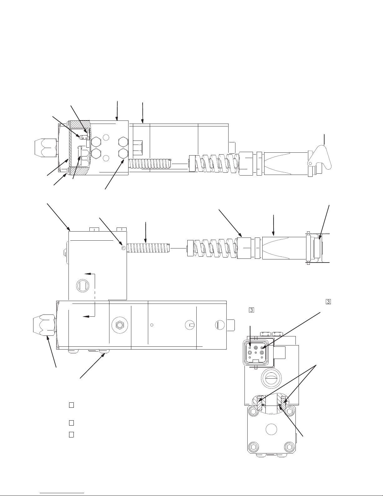
Models 244962, 244909, and 244951 (240 V. Models)
22 309376L
Page 23

Parts
Models 244962, 244909, and 244951 (240 V. Models)
Ref
No.
1 244535 VALVE, ext, dispense, 200 deg. F
1 244907 VALVE, ext, dispense, 400 deg. F
1 244937 VALVE, (model 244951) 1
2 198236 MANIFOLD, electrical 1
3 C32255 SENSOR, temperature 1
4 C32089 RETAINER, nozzle 1
5** 109576 PACKING, o-ring, fluroelastomer 1
6 116412 SCREW, cap, button head, M6 x 60 4
7 114618 PIN, dowel, dia. 3/16 x 1/2 lg 2
8 116614 HEATER, cartridge, 240 V 1
9 114185 SCREW, cap, button head 3
10 198232 GUARD, manifold, 1
Part
No.
Description Qty.
(model 244962)
(model 244909)
Repair Kits
Part No. Description
15E012 Standard seals
15E011 High temperature seals
Ref
No.
1
1
11 101674 TERMINAL, ring, ground 1
12 105672 SCREW, set, sch. 1
13 116675 CORD, flex, 1
14* 073019 LUBRICANT, thermal 1
15 116673 BUSHING, strain relief 1
16 116637 CONNECTOR, cable coupler hood 1
17 115860 INSERT, male 1
18 116640 CONTACT, connector 4
19 115862 CONNECTOR, male, crimp 1
20 065345 WIRE, copper, electrical
21 513035 SCREW, cap, shcs 4
22 197843 Block, mounting 1
* not shown
** Included in repair kits. Kits also include manifold o-rings for all
models.
Part
No.
Description Qty.
2 ft.
(16 AWG)
309376L 23
Page 24
Parts
5
7
19
18
6
22
12
13
15
16
4, 26
17
2
8
9, 11, 20
1
10
9
21
23
Notes:
Install sensor (3) and heater (8) with a coating of heat
sink compound (14)
Torque screws (6) evenly to 50-60 lb-in.
A pin crimper is used to make these connections.
Soldering is acceptable for replacements if a new pin is
used.
1
2
3
Ground wire
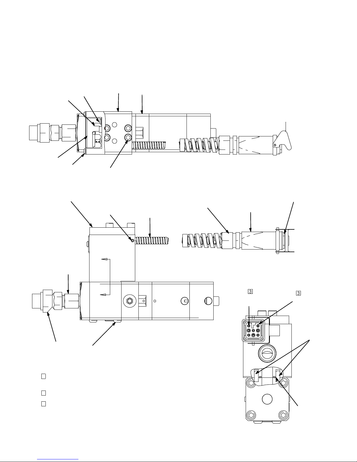
Model 297261 (240 V Model)
24 309376L
Page 25

Parts
Model 297261 (240 V Model)
Ref
Part No. Description Qty.
No.
1 244907 VALVE, ext, dispense, 400 deg. F 1
2 198236 MANIFOLD, electrical 1
4 118072 HEAD, applicator, swirl 1
5** 109576 PACKING, o-ring, fluroelastomer 1
6 116412 SCREW, cap, button head,
M6 x 60
7 114618 PIN, dowel, dia. 3/16 x 1/2 lg 2
8 116614 HEATER, cartridge, 240 V 1
9 114185 SCREW, cap, button head 3
10 198232 GUARD, manifold, 1
Repair Kits
Part No. Description
15E012 Standard seals
15E011 High temperature seals
Ref
Part No. Description Qty.
No.
11 101674 TERMINAL, ring, ground 1
12 105672 SCREW, set, sch. 1
13 116675 CORD, flex, 1
14* 073019 LUBRICANT, thermal 1
4
15 116673 BUSHING, strain relief 1
16 116637 CONNECTOR, cable coupler hood 1
17 115860 INSERT, male 1
18 116640 CONTACT, connector 4
19 115862 CONNECTOR, male, crimp 1
20 065345 WIRE, copper, electrical
(16 AWG)
21 513035 SCREW, cap, shcs 4
22 197843 Block, mounting 1
23 15H098 ADAPTER, swirl 1
26 117950 NOZZLE, swirl, .030 1
* not shown
** Included in repair kits. Kits also include manifold o-rings for all
models.
2 ft.
309376L 25
Page 26
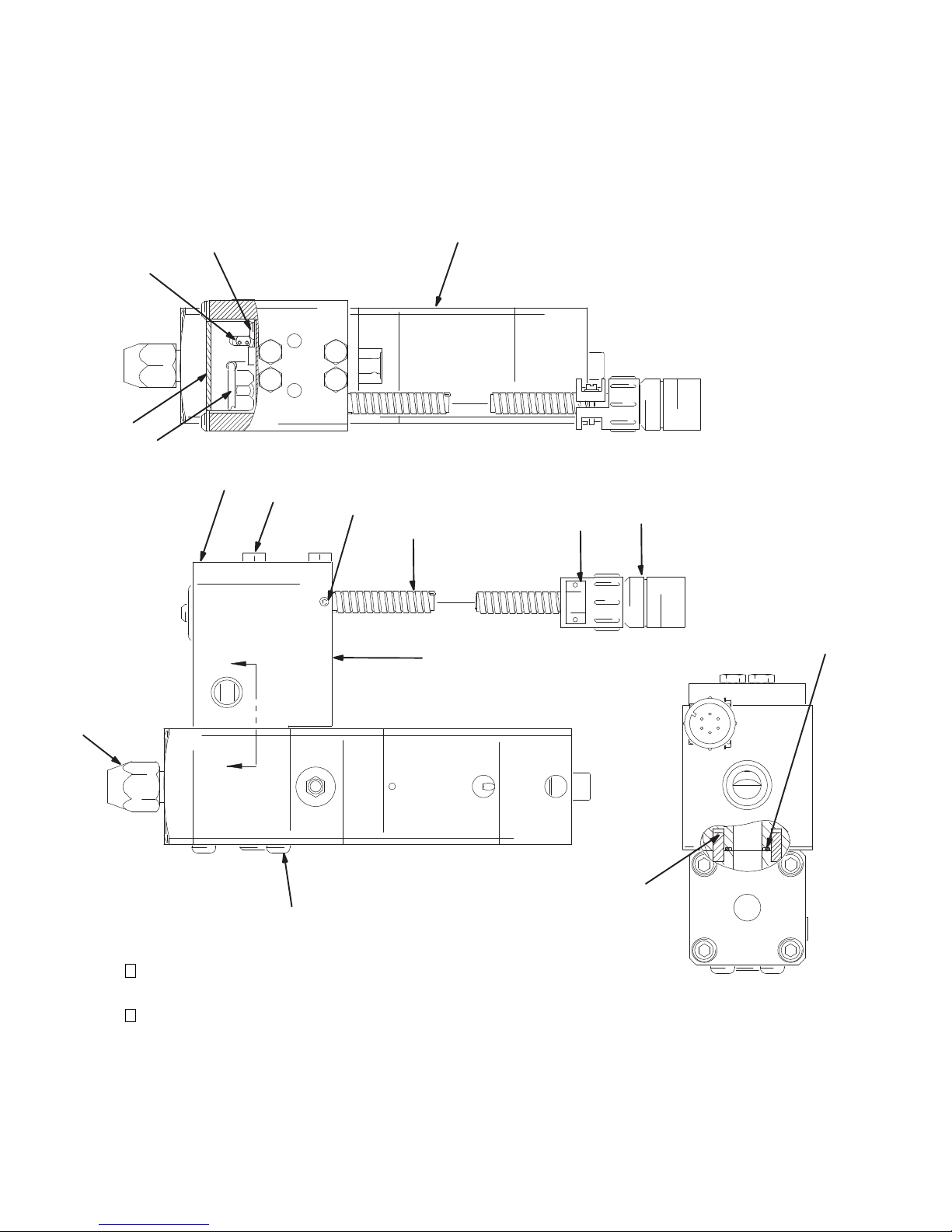
Parts
TI1384A
TI1384A
TI1384A
8
9, 11, 16
1
10
3
19
18
12
13
17
15
2
6
4
5
7
Notes:
Install sensor (3) and heater (8) with a coating of heat
sink compound (14)
Torque screws (6) evenly to 50-60 in/lbs
1
2
Models 244961, 244908, and 245184 (120 V. Models)
26 309376L
Page 27

Parts
Models 244961, 244908, and 245184 (120 V. Models)
Ref
Part No. Description Qty.
No.
1 244535 VALVE, ext, dispense, 200 deg. F
(model 244961)
1 244907 VALVE, ext, dispense, 400 deg. F
(model 244908)
1 244937 VALVE, ext, dispense, 1/2 npt
(model 245184)
2 198236 MANIFOLD, electrical 1
3 C32255 SENSOR, temperature 1
4 C32089 RETAINER, nozzle 1
5** 109576 PACKING, o-ring, fluroelastomer 1
6 116412 SCREW, cap, button head,
7 114618 PIN, dowel, dia. 3/16 x 1/2 lg 2
M6 x 60
Repair Kits
Part No. Description
15E012 Standard seals
15E011 High temperature seals
1
1
1
4
Ref
No.
8 116613 HEATER, cartridge, 120 V 1
9 114185 SCREW, cap, button head 3
10 198232 GUARD, manifold, 1
11 101674 TERMINAL, ring, ground 1
12 105672 SCREW, set, sch. 1
13 116675 CORD, flex, 1
14* 073019 LUBRICANT, thermal 1
15 116639 CONNECTOR, receptacle, male 1
16 065345 WIRE, copper, electrical
17 116688 CLAMP, cable 1
18 513035 SCREW, cap, shcs 4
19 197843 Block, mounting 1
* not shown
** Included in repair kits. Kits also include manifold o-rings for all
models.
Part No. Description Qty.
2 ft.
(16 AWG)
309376L 27
Page 28
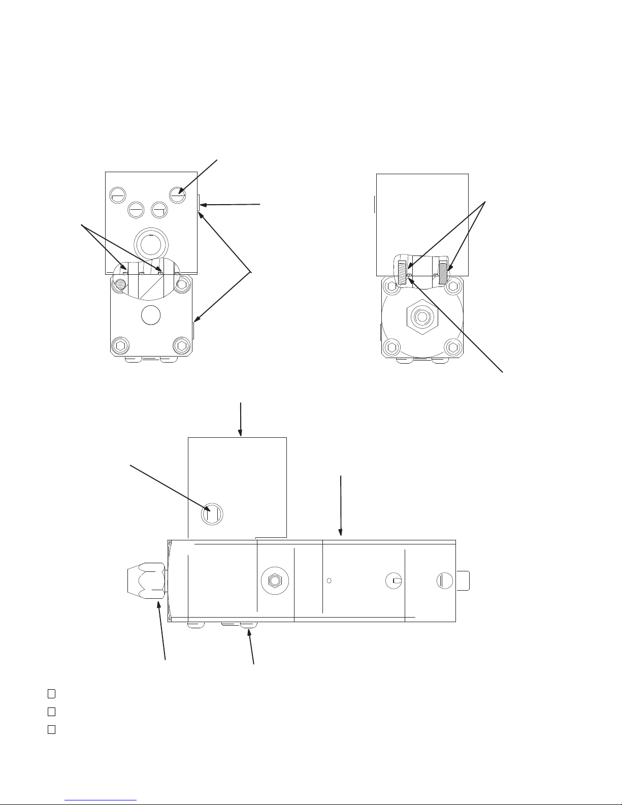
Parts
1
TI1378A
TI1378A
TI1378A
4
2
6
8
5
10
7
(1) 1/4 npt water
circulation inlet port
(4) 1/8 npt(f) water
circulation outlet ports
(2) 1/8 npt(f)
RTD sensor ports
1
2
3
Model 244910 (ambient or temperature conditioned)
Notes:
Apply pipe sealant to threads per G standard 4.0520
Torque screws (7) evenly to 50–60 lb-in.
Mounting screws (9) loose with valve
28 309376L
Page 29

Parts
Model 244910 (ambient or temperature conditioned)
Ref
Part No. Description Qty.
No.
1 244535 VALVE, ext, dispense, 200 deg. F 1
2 198235 MANIFOLD, water 1
3* 070408 SEALANT, pipe, sst 1
4 110208 PLUG, pipe, headless 5
5** 109576 PACKING, o-ring, fluroelastomer 1
6** 106555 PACKING, o-ring 2
Repair Kits
Part No. Description
15E012 Standard seals
15E011 High temperature seals
Ref
No.
7 116412 SCREW, cap, button head 4
8 114618 PIN, dowel dia 3/16 x 1/2 lg 2
9 513035 SCREW, cap, shcs 4
10 C32089 RETAINER, seat 1
* not shown
** Included in repair kits. Kits also include manifold o-rings for all
models.
Part No. Description Qty.
309376L 29
Page 30

Accessories
Use Only Genuine Graco Parts and Accessories
Description Part No.
Tube Fittings for Air or Water
Suggested air fittings for automatic dispense valve air inlet ports. Do not use fittings with
temperature ratings that are lower than the operating temperature of your system. Contact your
Graco Service Representative for more information. These fittings are rated for at least 150 psi at
140°F.
°
elbow, push-in tube 1/8” male 1/4” O.D. 597151
90
°
elbow, push-in tube 1/8” male 5/32” (4mm) 198171
90
Straight push-in tube 1/8” male 1/4” O.D. 104172
Straight push-in tube 1/8” male 5/32” (4mm) 114263
For heated hoses reference 309160.
Solenoid Valve Kits for High Temperature Valves
For heated double acting air actuated valves. Includes solenoid, 24” high temperature air tubes,
air fittings, and muffler.
Hose and Cable Kit
8 pin square female connector and 10 ft. of cable to mate with 240 VAC valves 244021
Quick Exhaust Valve
1/8 npt(f) 104661
Temperature Conditioning Accessories (Water Circulation)
RTD Sensor. 1/8 npt(m) x .81” (21mm) insertion length
3 pin Picofast connector fits the cable below
Sensor cable. 6 ft. (1.8 m) 198458
3-pin Picofast 90° connector for RTD above (198457)
3-pin Omega connector on control end. Fits St. Clair temperature conditioning cable.
NOTE: The following accessories are not applicable to Model 297261.
Swirl Orbiter Adapters
Alternate nosepiece for valve outlet. 3/4-16 JIC(m). Fits inlet swivel on orbiter 197504
45° orbiter mount uses the following parts:
45° Nosepiece 197842
Alternate orbiter nut 198323
Fitting nosepiece to orbiter 198324
Streaming Adapter
Alternate outlet nut to retain 270xxx streaming tips or 182xxx fan tips (See Manual 308813) 617585
Steel Dispense Nozzles
1/8 npt (m)
Repair Kits
Standard seals 15E012
High temperature seals 15E011
NPT Tube
Coil Voltage C58942
120 Volt AC 243703
230 Volt AC C59038
24 Volt DC
198457
Length Orifice Size
2” .125 607665
2” .094 161505
2.12” .055 164799
1.22” .125 C17009
2.43” .09 x.37 ribbon hardened tip C01025
30 309376L
Page 31

Accessories
Description Part No.
Cable Wrap
10” x 10” nylon fabric pad with Velcro strip. Used to secure the valve cable connector to the
heated hose. Protects the electrical connectors in applications where the valve is being moved.
Velcro Straps
1” x 12” strap used to secure ends of wrap 198422 above. 198442
Fluid Inlet Adapters
1/2” NPT(m) x No. 8 JIC(m) (3/4 –16 with 37° flare)
1/2” NPT(m) x No. 10 JIC(m) (7/8 –14 with 37° flare)
1/2” NPT(m) x No. 12 JIC(m) (1-1/16 –12 with 37° flare)
Grease Gun
3 oz. cartridge 551189
198422
C20700
C20703
C20642
309376L 31
Page 32
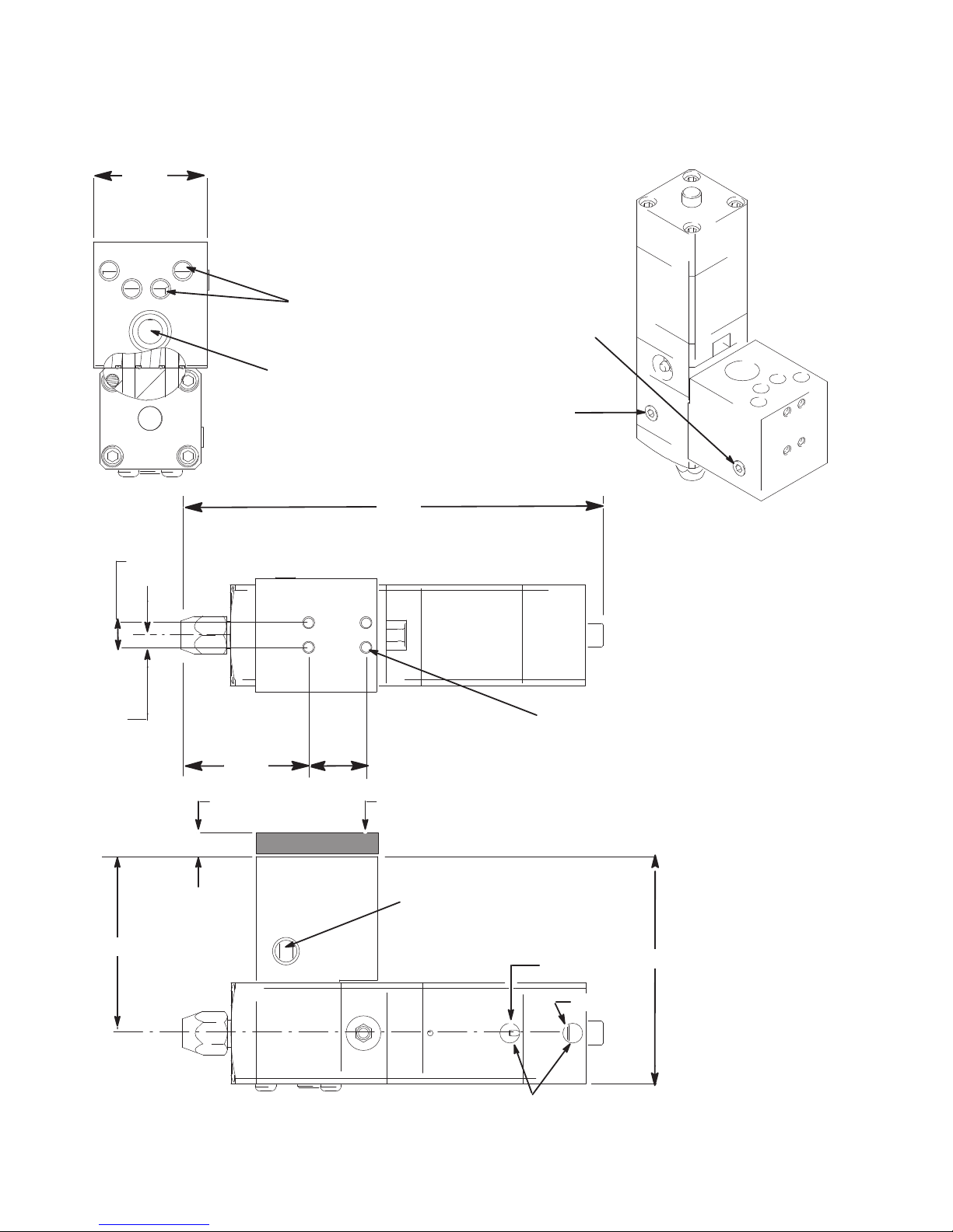
Dimensions
TI1377A
TI1378A
2.250
(4) 1/8 npt(f) temperature
conditioning water outlets
1/2 npt(f) process fluid
inlet
1/8 npt(f)
RTD
sensor
port
Optional
RTD port
8.310
.489
.244
2.531
1.135
(4) M6 x 1 mounting holes x .46” (11.6 mm)
full thread depth
Electrically heated models have
an insulating mounting block
.375
3.500
4.500
1/4 npt(f) temperature
conditioning water inlet
Air to close
Air to open
1/8 npt(f)
32 309376L
Page 33
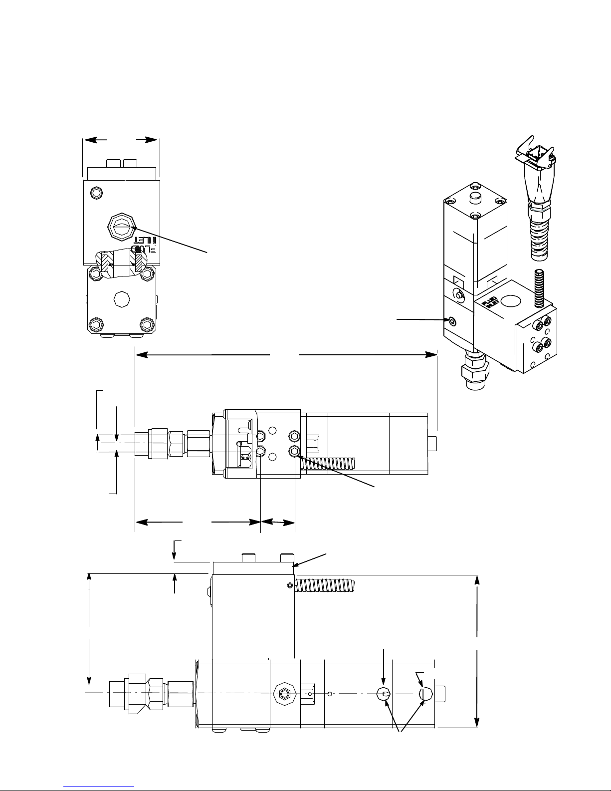
Dimensions
2.250
Optional
RTD port
9.86
.489
.244
3.215
1.135
(4) M6 x 1 mounting holes x .46” (11.6 mm)
full thread depth
Electrically heated models have
an insulating mounting block
.375
3.500
4.500
Air to close
Air to open
1/8 npt(f)
1/2 npt(f) process
fluid inlet
Model 297261 Only
309376L 33
Page 34

Technical Data
Maximum working fluid pressure 24.1 MPa (241 bar, 3500psi)
Maximum static fluid pressure 34.5 MPa (345 bar, 5000 psi)
Maximum working dry air pressure .83 MPa (8.3 bar,120 psi)
Maximum working temperature
Standard seals in models 244535, 244910,
244961, 244962 95°C (200°)
High temperature seals in models 244907,
244908, 244909, 244937, 244951, 245184 204°C (400°)
Material Inlet on inlet manifold (all models) 1/2" npt(f)
Air Inlets (open and close) 1/8" npt
120 Volt Heater 150w @ 120 VAC, 96 ohms +/-10
pins C and F
240 Volt Heater 200w @ 240 VAC, 288 ohms +30/-40
pins 1 and 2
RTD Sensor (120 Volt models - pins A and B) 100 Ohm platinum RTD, 0.00385 ohm/ohm/deg C
(240 Volt models - pins 3 and 4) (108.2 ohms @ 21° C (70° F))
Weight (automatic dispense valve + manifold) approx. 1.8 kg (4 lbs)
Model 244910 can be temperature conditioned with circulating water. The valve/manifold is equipped with:
(1) 1/4 npt(f) water inlet
(4) 1/8 npt(f) water outlets
(2) 1/8 npt(f) ports that can be used for a temperature sensor (see page 30).
WETTED PARTS (all valves)
Aluminum, Stainless Steel, chrome, carbide, acetal plastic, PTFE, fluoroelastomer
PRIMARY SEAL MATERIALS
Model 244535 - Polymyte
®
(orange) standard temperature
Models 244907 and 244937 - graphite fiber reinforced PTFE (black) high temperature
Material Outlet
244951 and 245184 1/2 npt(m)
244910, 244961, 244962,
244908, 244909
Polymyte is a trademark of Parker Seal.
5/8–18 with nut to accept
1/8 npt nozzles
34 309376L
Page 35
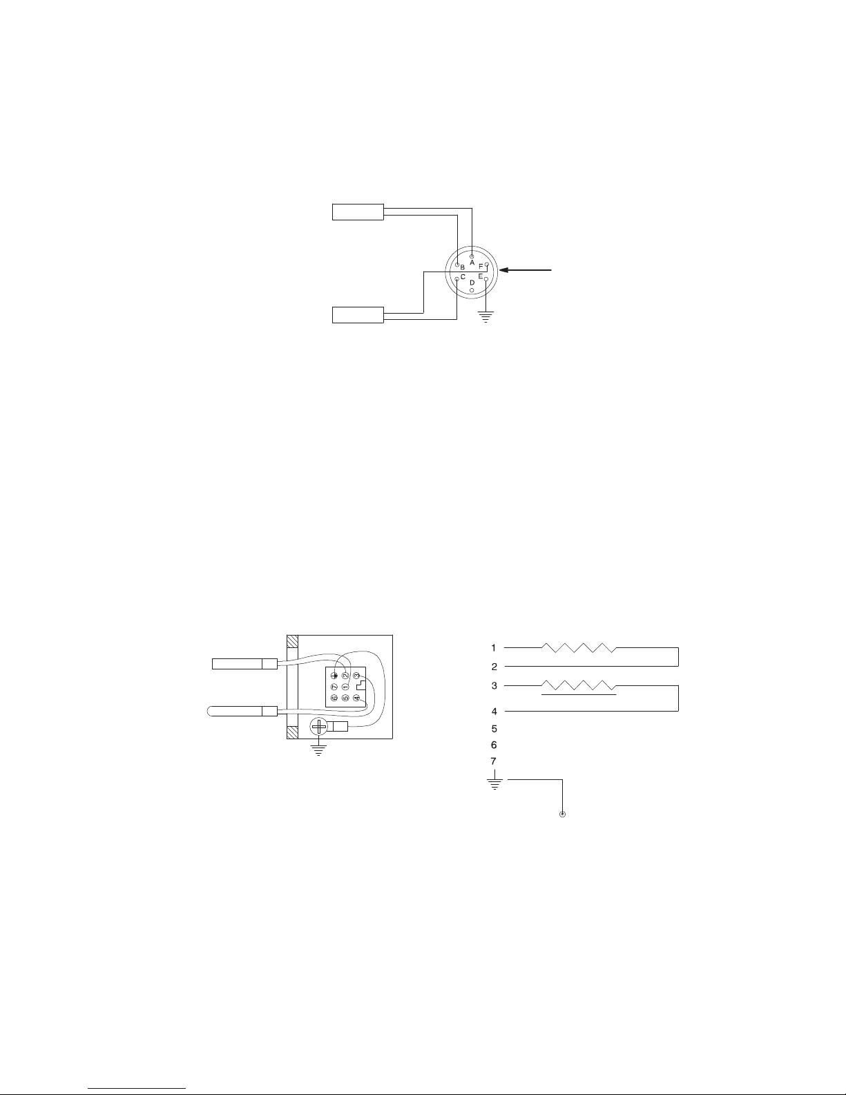
Wiring Diagram
SENSOR RTD
All Therm-O-Flow Plus™ accessories
HEATER
SENSOR
(NOT USED)
(NOT USED)
(NOT USED)
SENSOR RTD
120 Volt Models
108 +/–1 Ω @ 70°F
90–100 Ω @ 70°F
HEATER 150 W @ 120 VOLTS
NOTE: ALLOW SUFFICIENT LEAD LENGTH TO BE ABLE TO
ROTATE CONNECTOR BRACKET ±
18, 36
180.
Past Therm-O-Flow™ accessories
240 Volt Models
248-318
108 +/–1 Ω @ 70°F
Ω @ 70°F
HEATER
200 W @ 240 VOLTS
SCHEMATIC DIAGRAMWIRING DIAGRAM
309376L 35
Page 36

Graco Standard Warranty
Graco warrants all equipment referenced in this document which is manufactured by Graco and bearing its name to be free from defects in
material and workmanship on the date of sale to the original purchaser for use. With the exception of any special, extended, or limited warranty
published by Graco, Graco will, for a period of twelve months from the date of sale, repair or replace any part of the equipment determined by
Graco to be defective. This warranty applies only when the equipment is installed, operated and maintained in accordance with Graco's written
recommendations.
This warranty does not cover, and Graco shall not be liable for general wear and tear, or any malfunction, damage or wear caused by faulty
installation, misapplication, abrasion, corrosion, inadequate or improper maintenance, negligence, accident, tampering, or sub- stitution of
non-Graco component parts. Nor shall Graco be liable for malfunction, damage or wear caused by the incompatibility of Graco equipment with
structures, accessories, equipment or materials not supplied by Graco, or the improper design, manufacture, installation, operation or
maintenance of structures, accessories, equipment or materials not supplied by Graco.
This warranty is conditioned upon the prepaid return of the equipment claimed to be defective to an authorized Graco distributor for verification of
the claimed defect. If the claimed defect is verified, Graco will repair or replace free of charge any defective parts. The equipment will be returned
to the original purchaser transportation prepaid. If inspection of the equipment does not disclose any defect in material or workmanship, repairs
will be made at a reasonable charge, which charges may include the costs of parts, labor, and transportation.
THIS WARRANTY IS EXCLUSIVE, AND IS IN LIEU OF ANY OTHER WARRANTIES, EXPRESS OR IMPLIED, INCLUDING BUT NOT
LIMITED TO WARRANTY OF MERCHANTABILITY OR WARRANTY OF FITNESS FOR A PARTICULAR PURPOSE.
Graco's sole obligation and buyer's sole remedy for any breach of warranty shall be as set forth above. The buyer agrees that no other remedy
(including, but not limited to, incidental or consequential damages for lost profits, lost sales, injury to person or property, or any other incidental or
consequential loss) shall be available. Any action for breach of warranty must be brought within two (2) years of the date of sale.
GRACO MAKES NO WARRANTY, AND DISCLAIMS ALL IMPLIED WARRANTIES OF MERCHANTABILITY AND FITNESS FOR A
PARTICULAR PURPOSE, IN CONNECTION WITH ACCESSORIES, EQUIPMENT, MATERIALS OR COMPONENTS SOLD BUT NOT
MANUFACTURED BY GRACO.
These items sold, but not manufactured by Graco (such as electric motors, switches, hose, etc.), are subject to the warranty, if any, of their
manufacturer. Graco will provide purchaser with reasonable assistance in making any claim for breach of these warranties.
In no event will Graco be liable for indirect, incidental, special or consequential damages resulting from Graco supplying equipment hereunder, or
the furnishing, performance, or use of any products or other goods sold hereto, whether due to a breach of contract, breach of warranty, the
negligence of Graco, or otherwise.
FOR GRACO CANADA CUSTOMERS
The parties acknowledge that they have required that the present document, as well as all documents, notices and legal proceedings entered into,
given or instituted pursuant hereto or relating directly or indirectly hereto, be drawn up in English. Les parties reconnaissent avoir convenu que la
rédaction du présent document sera en Anglais, ainsi que tous documents, avis et procédures judiciaires exécutés, donnés ou intentés à la suite
de ou en rapport, directement ou indirectement, avec les procedures concernées.
Graco Information
For the latest information about Graco products, visit www.graco.com.
For patent information, see www.graco.com/patents.
TO PLACE AN ORDER, contact your Graco distributor or call to identify the nearest distributor.
Phone: 612-623-6921 or Toll Free: 1-800-328-0211 Fax: 612-378-3505
All written and visual data contained in this document reflects the latest product information available at the time of publication.
GRACO INC. AND SUBSIDIARIES • P.O. BOX 1441 • MINNEAPOLIS MN 55440-1441 • USA
Copyright 2004, Graco Inc. All Graco manufacturing locations are registered to ISO 9001.
Graco reserves the right to make changes at any time without notice.
Original instructions. This manual contains English. MM 309376
International Offices: Belgium, China, Japan, Korea
Graco Headquarters: Minneapolis
www.graco.com
Revision L, September 2018
 Loading...