

Page 1
Instructions-Parts
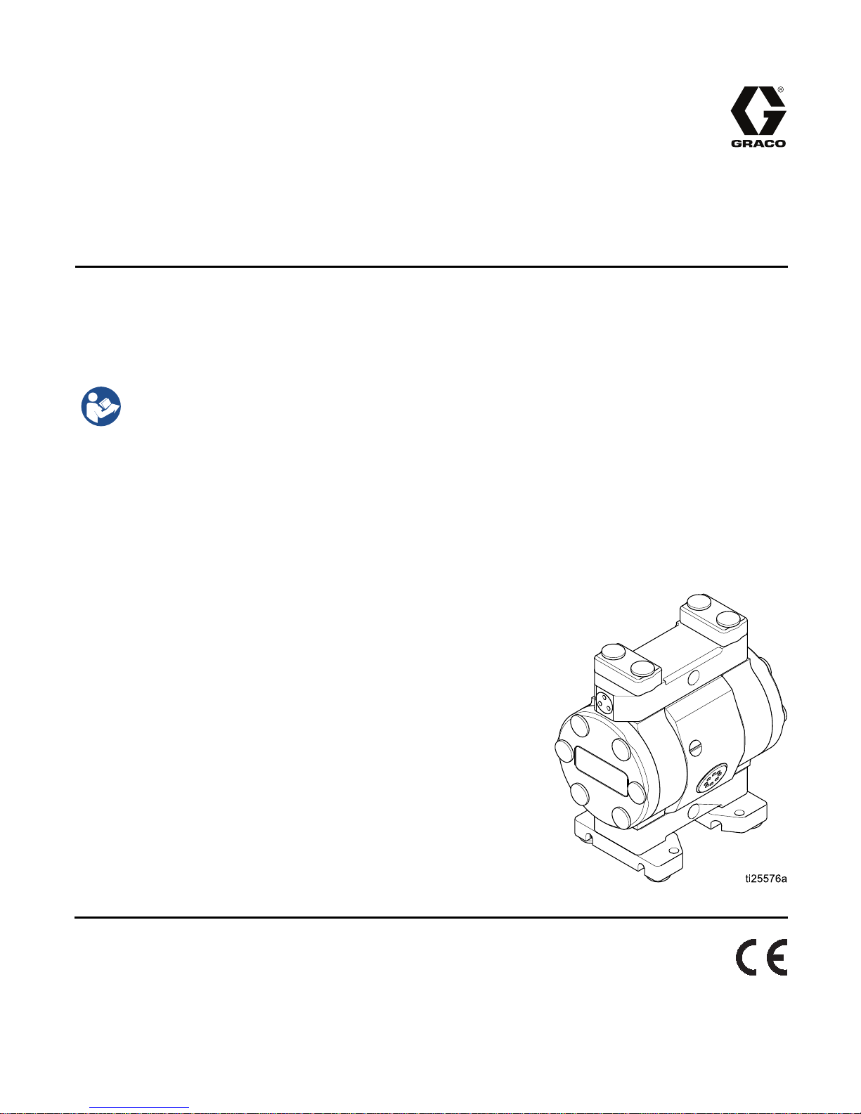
ChemSafe™ 205
Air-Operated
1/4–inch hig
Not approved for use in European explosive atmosphere locations.
100 psi (0.7 MPa, 7.0 bar) Maximum Air
Supply Pressure
100 psi (0.7 MPa, 7.0 bar) Maximum
Fluid Working Pressure
h purity pump for industrial applications.For professional use only.
Important
Read all warnings and instructions in this manual. Save these
instructions.
Safety Instructions
Diaphragm Pump
334792E
EN
PROVEN QUALITY. LEADING TECHNOLOGY.
Page 2

Contents
Warnings ........................................................... 3
Configuration Number Matrix............................... 6
Installatio
Operation........................................................... 13
Maintenance ...................................................... 15
n.......................................................... 8
General Info
Tighten Fast
Tips to Reduc
Mount The Pu
Ground The S
Air Lines...................................................... 10
Air Exhaust
Fluid Suppl
Fluid Outl
Tighten Fasteners........................................ 13
Flush the Pump Before First Use .................. 13
Start and Adjust the Pump............................ 13
Pressure Relief Procedure............................ 14
Pump Shutdown .......................................... 14
Maintenance Schedule................................. 15
Lubrication................................................... 15
rmation ..................................... 8
eners........................................ 8
e Cavitation............................. 8
mp ......................................... 9
ystem ..................................... 10
Ventilation ................................. 11
y Line ......................................... 12
et Line........................................... 12
Tighten Threaded Connections..................... 15
Flushing and Storage ................................... 15
Troubleshooting.................................................. 16
Repair................................................................ 18
Disassemble
Disassemble
Reassemble
Reassemble
Torque Instructions............................................. 22
Notes................................................................. 23
Parts.................................................................. 24
Kits.................................................................... 26
Dimensions ........................................................ 27
Performan
Technical Data ...................................................29
Graco Standard ChemSafe Pump
ce Charts............................................ 28
Warranty............................................... 30
the Fluid Section...................... 18
the Center Section ................... 19
the Center Section.................... 19
the Fluid Section....................... 20
2
334792E
Page 3
Warnings
Warnings
The following warnings are for the setup, use, grounding, maintenance, and repair of this equipment. The
exclamation point symbol alerts you to a general warning and the hazard symbols refer to procedure-specific
risks. When these symbols appear in the body of this manual or on warning labels, refer back to these
Warnings. Product-specific hazard symbols and warnings not covered in this section may appear throughout
the body of this manual where applicable.
WARNING
FIRE AND EX
Flammable fumes, such as solvent and paint fumes, in work area can ignite or explode. To help
prevent fire and explosion:
• Use equipment only in well ventilated area.
• Eliminate all ignition sources; such as pilot lights, cigarettes, portable electric lamps, and
plastic drop cloths (potential static arc).
•Keepwork
• Do not plug or unplug power cords, or turn power or light switches on or off when flammable
fumes are present.
• Ground all equipment in the work area. See Grounding instructions.
•Useonly
• Hold gun firmly to side of grounded pail when triggering into pail. Do not use pail liners unless
they are antistatic or conductive.
• Stop operation immediately if static sparking occurs or you feel a shock. Do not use
equipment until you identify and correct the problem.
• Keepaw
• Route exhaust away from all ignition sources. If diaphragm ruptures, fluid may be exhausted
with air.
c charge may build up on plastic parts during cleaning and could discharge and ignite
Stati
flamma
• Clean plastic parts only in well ventilated area.
• Do not
• Do not operate electrostatic guns in equipment work area.
ble vapors. To help prevent fire and explosion:
PLOSION HAZARD
area free of debris, including solvent, rags and gasoline.
grounded hoses.
orking fire extinguisher in the work area.
cleanwithadrycloth.
PRESSURIZED EQUIPMENT HAZARD
Fluid from the equipment, leaks, or ruptured components can splash in the eyes or on skin
and cause serious injury.
low the Pressure Relief Procedure when you stop spraying/dispensing and before
•Fol
aning, checking, or servicing equipment.
cle
• Tighten all fluid connections before operating the equipment.
• Check hoses, tubes, and couplings daily. Replace worn or damaged parts immediately.
334792E 3
Page 4
Warnings
WARNING
EQUIPMENT MISUSE HAZARD
Misuse can ca
• Do not operate the unit when fatigued or under the influence of drugs or alcohol.
• Do not exceed
system compo
• Use fluids and solvents that are compatible with equipment wetted parts. See Technical Data
in all equipment manuals. Read fluid and solvent manufacturer’s warnings. For complete
information about your material, request MSDS from distributor or retailer.
• Do not leave the work area while equipment is energized or under pressure.
•Turnoffall
• Check equipment daily. Repair or replace worn or damaged parts immediately with genuine
manufacturer’s replacement parts only.
• Do not alter or modify equipment. Alterations or modifications may void agency approvals
and create safety hazards.
•Makesure
• Use equipment only for its intended purpose. Call your distributor for information.
• Route hoses and cables away from traffic areas, sharp edges, moving parts, and hot surfaces.
• Do not kin
• Keep children and animals away from work area.
• Comply with all applicable safety regulations.
THERMAL
Fluids subjected to heat in confined spaces, including hoses, can create a rapid rise in pressure
due to the thermal expansion. Over-pressurization can result in equipment rupture and serious
injury.
use death or serious injury.
the maximum working pressure or temperature rating of the lowest rated
nent. See Technical Data in all equipment manuals.
equipment and follow the Pressure Relief Procedure when equipment is not in use.
all equipment is rated and approved for the environment in which you are using it.
k or over bend hoses or use hoses to pull equipment.
EXPANSION HAZARD
• Open a valve to relieve the fluid expansion during heating.
• Replace hoses proactively at regular intervals based on your operating conditions.
TIC PARTS CLEANING SOLVENT HAZARD
PLAS
Many solvents can degrade plastic parts and cause them to fail, which could cause serious
injury or property damage.
• Use only compatible water-based solvents to clean plastic structural or pressure-containing
parts.
•SeeTechnical Data in this and all other equipment instruction manuals. Read fluid and
solvent manufacturer’s MSDSs and recommendations.
4
334792E
Page 5
WARNING
TOXIC FLUID OR FUMES HAZARD
Warnings
Toxic fluids o
inhaled, or s
• Read MSDSs to know the specific hazards of the fluids you are using.
• Route exhaus
the air.
• Store hazardous fluid in approved containers, and dispose of it according to applicable
guidelines.
BURN HAZARD
Equipment surfaces and fluid that’s heated can become very hot during operation. To avoid
severe burns:
• Do not touch hot fluid or equipment.
PERSONAL PROTECTIVE EQUIPMENT
Wear appropriate protective equipment when in the work area to help prevent serious injury,
including eye injury, hearing loss, inhalation of toxic fumes, and burns. This protective
equipment includes but is not limited to:
•Protect
• Respirators, protective clothing, and gloves as recommended by the fluid and solvent
manufacturer.
r fumes can cause serious injury or death if splashed in the eyes or on skin,
wallowed.
t away from work area. If diaphragm ruptures, fluid may be exhausted into
ive eyewear, and hearing protection.
334792E 5
Page 6
Configuration Nu
mber Matrix
Configuration
Number
Matrix
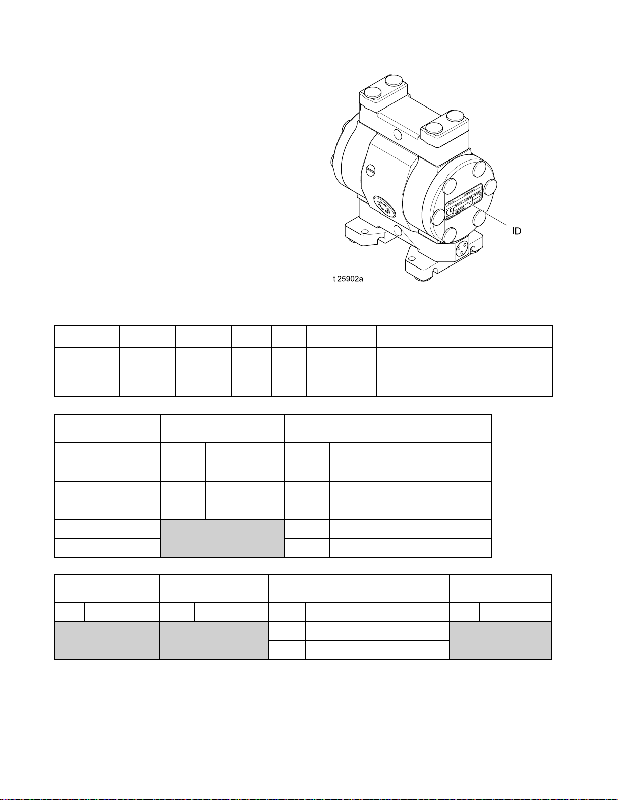
Check the iden
Configuratio
following ma
pump.
Sample Con
205PT P01A PT3
Pump
Model
tification plate (ID) for the
n Number of your pump. Use the
trix to define the components of your
figuration Number:
Center
Section
and Air
Valve
Fluid
Covers
and
Manifol
205PT-P01APT3PTPTPOPT
PT PT
Seats
ds
Balls Diaphrag
PO
PT
ms
Manifold and Seat Seals
Pump
205PT
1/4 in.PTFE
205 UH
. UHMWPE
1/4 in
Seat Material
PTFE
PT
Center Section and Air
Valve Material
P01A
P03A
Ball Material Diaphragm Material
PT
Polypropylene
center with npt
air inlet
ropylene
Polyp
rwith
cente
ir inlet
bspt a
PTFE
Fluid Covers and Manifolds
PT3
PT4
UH3
UH4
BN
EP
PO
PTFE, npt
PTFE,
UHMWPE, npt
UHMWPE, bspt
N
Buna
EPDM
E Overmolded
PTF
bspt
Manifold and Seat
Seal Material
PTFE
PT
6 334792E
Page 7

Models
Configuration Nu
mber Matrix
Model Pump
24X430
24X429
24X511
24X509
24X532
24X533
24X508
24X507
1/4 in. PTFE
1/4 in.
UHMWPE
Air & Fluid
Connection
Threads
bspt
npt
bspt
npt
bspt
npt
bspt
npt
Fluid Covers &
Manifolds
PTFE
UHMW
Balls &
Seats
PTFE
Diaphragm
PTFE/EPDM
Overmolded
EPDM
Buna N
Manifold Seal
PTFE
334792E
7
Page 8

Installation
Installation
General Information
The Typical I
selecting an
your Graco di
system to sui
Graco Parts
are adequat
system’s re
Reference letters in the text, for example (A), refer to
the callouts in the figures.
Variations in color between the plastic components
of this pump are normal. Color variation does not
affect the performance of the pump.
Storage: P
upon deli
Flushing
nstallation shown is only a guide for
d installing system components. Contact
stributor for assistance in planning a
t your needs. Always use Genuine
and accessories. Be sure all accessories
ely sized and pressure rated to meet the
quirements.
umps that are not put into operation
very must be stored appropriately. See
and Storage, page 15.
Tighten Fasteners
Before m
first tim
Remove
Torque
Replac
operat
pump ha
in ther
or if t
tempe
ounting and using the pump for the
e, check and retorque all external bolts.
all protective bolt covers (37). Follow
Instructions, page 22, to tighten all bolts.
e the bolt covers (37). After the first day of
ion, retorque the bolts. Retorque the bolts if the
s been idle for an extended time, been used
mal cycling applications, been disassembled,
here is a large difference between environmental
ratures and fluid temperatures.
Tips to Reduce Cavitation
Cavitation i
collapse of b
or excessive
including pi
balls, and s
the pump. Ca
both result
Cavitation depends on the vapor pressure of the
pumped liquid, the system suction pressure, and the
velocity pressure. It can be reduced by changing any
of these factors.
1. Reduce vapor pressure: Decrease the
temperature of the pumped liquid.
2. Increase suction pressure:
a. Lower the
b. Reduce t
c. Increas
3. Reduce
the pum
Pumped liquid viscosity is also very important but
normally is controlled by factors that are process
dependent and cannot be changed to reduce
cavitation. Viscous liquids are more difficult to pump
and more prone to cavitation.
n an AODD pump is the formation and
ubbles in the pumped liquid. Frequent
cavitation can cause serious damage,
tting and early wear of fluid chambers,
eats. It may result in reduced efficiency of
vitation damage and reduced efficiency
in increased operating costs.
installed position of the pump
relative
piping.
length t
fittings
to the liquid level in the supply.
he friction length of the suction
Remember that fittings add friction
o the piping. Reduce the number of
to reduce the friction length.
e the size of the suction piping.
liquid velocity: Slow the cyclic rate of
p.
8 334792E
Graco recommends taking all the above factors
into account in system design. To maintain pump
efficiency, supply only enough air pressure to the
pump to achieve the required flow.
o distributors can supply site specific
Grac
estions to improve pump performance and
sugg
ce operating costs.
redu
Page 9

Mount The Pump
To avoid serious injury from toxic fluid or fumes:
• Ventilate to a remote area. The pump
exhaust air may contain contaminants. See
Air Exhaust Ventilation, page 11.
• Never move or lift a pump under pressure. If
dropped, the fluid section may rupture. Always
follow the Pressure Relief Procedure, page 14,
before moving or lifting the pump.
1. Mount the pump so the exhaust port remains
clear of the production area. Exhaust air may
contain debris and condensation from the air
supply and air chamber.
Installation
2. Be sure the mounting surface can support the
weight of the pump, hoses, and accessories, as
well as the stress caused during operation.
3. For all mountings, be sure the pump is secured
with screws through the mounting feet. Always
mount the pump upright.
4. Make sure the surface is flat and that the pump
doesn’t wobble.
5. For ease of operation and service, mount the
pump so air inlet, fluid inlet and fluid outlet ports
are easily accessible.
ssories/Components Not Supplied
Acce
A Air supply line J Air inlet port
B
C Air filter/regulator assembly
D
E
F
GF
H
d-type master air valve (required
Blee
our pump)
for y
Master air valve (to isolate the
filter/regulator for service)
Grounded flexible fluid supply line
Fluid drain valve (required for your
pump)
luid shutoff valve
rounded, flexible fluid outlet line
G
334792E 9
em Components
Syst
K
L Fluid inlet port
M Fluid outlet port
N
ust port and muffler
Exha
Mounting feet
Page 10

Installation
Ground The Sys
The equipment must be grounded to reduce the
risk of static sparking. Static sparking can cause
fumes to ignite or explode. Grounding provides an
escape wire for the electrical current.
• Always ground the entire fluid system as
described below.
• The pumps are not conductive. Any system
used to pump flammable fluids must be properly
grounded.
• Follow your local fire codes.
Before operating the pump, ground the system as
explained below.
• Pump: Always ground the entire fluid system by
making sure the fluid has an electrical path to a
true earth ground.
• Air and fluid hoses: Use only flexible grounded
hoses with a maximum of 500 ft. (150 m) combined
hose length to ensure grounding continuity.
• Air compressor: Follow manufacturer’s
recommendations.
• Fluid supply container: Follow local code.
• Solvent pails used when flushing: Follow local
code. Use only conductive metal pails, placed
on a grounded surface. Do not place the pail
on a nonconductive surface, such as paper or
cardboard, which interrupts grounding continuity.
tem
Air Lines
1. Install an air
the fluid press
thesameasthe
2. Locate a bleed
the pump and u
sure the valv
and located d
Trapped air can cause the pump to cycle
unexpectedly, which could result in serious
injury from splashing.
3. Locate ano
from all a
them duri
4. An air lin
moisture
5. Install a
the acce
pump air
ID.Ifah
use a lar
regulator and gauge (C) to control
ure. The fluid stall pressure will be
setting of the air regulator.
-typemasterairvalve(B)closeto
se it to relieve trapped air. Be
e is easily accessible from the pump
ownstream from the regulator.
ther master air valve (D) upstream
ir line accessories and use it to isolate
ng cleaning and repair.
e filter (C) removes harmful dirt and
from the compressed air supply.
grounded, flexible air hose (A) between
ssories and the 1/8 npt(f) or 1/8 bspt
inlet. Use a hose with a minimum 1/4 in.
ose longer than 10 ft. (3 m) is required,
ger diameter hose.
Check your system electrical continuity after the
initial installation, and then set up a regular schedule
for checking continuity to be sure proper grounding
is maintained.
10 334792E
Page 11

Installation
Air Exhaust Ventilation
If pumping toxic fluids, you must vent the exhaust
away from people, animals, food handling areas,
and all sources of ignition. Follow all applicable
codes.
NOTE: Do not restrict the air exhaust port. Excessive
exhaust restriction can cause erratic pump operation.
To provide a remote exhaust:
1. Use Kit 17F610 (
separately.
2. Remove the muf
exhaust port (
3. Install the a
4. Install a gro
longer than 1
diameter hos
the hose.
5. Place a cont
linetocatc
If the diaph
will exhaus
NPT) or 17F611 (BSPT), sold
fler (U) from the pump air
K).
daptor from the kit.
unded air exhaust hose (S). If a hose
0 ft. (3 m) is required, use a larger
e. Avoid sharp bends or kinks in
ainer (T) at the end of the air exhaust
h fluid in case a diaphragm ruptures.
ragm ruptures, the fluid being pumped
t with the air.
A Air supply line
J
K Exhaust port U
Air inlet port (not visible)
S Grounded air exhaust hose
T
Container for remote air exhaust
Muffler
334792E
11
Page 12

Installation
Fluid Supply L
1. Use grounded, flexible fluid hoses (E). See
Ground The System, page 10.
2. If the inlet fluid pressure to the pump is more
than 25% of the outlet working pressure, the
ball check valves will not close fast enough,
resulting in inefficient pump operation. Excessive
inlet fluid pressure also will shorten diaphragm
life. Approximately 3–5 psi (0.02–0.03 MPa,
0.21–0.34 bar) should be adequate for most
materials.
ine
3. For maximum suction lift (wet and dry), see
Technical Data, page 29. For best results, always
install the pump as close as possible to the
material source. Minimize suction requirements
to maximize pump performance.
Fluid Outlet
1. Use grounded, flexible fluid hoses. See
Ground The System, page 10,
2. Install a fluid drain valve (F) near the fluid outlet.
3. Install a shutoff valve (G) in the fluid outlet line.
Line
2
1
334792E
Page 13

Operation
Operation
Tighten Faste
Before mounting and using the pump for the
first time, check and retorque all external bolts.
Remove all protective bolt covers (37). Follow
Torque Instructions, page 22, to tighten all bolts.
Replace the bolt covers (37). After the first day of
operation, retorque the bolts. Retorque the bolts if the
pump has been idle for an extended time, been used
in thermal cycling applications, been disassembled,
or if there is a large difference between environmental
temperatures and fluid temperatures.
Flush the P
The pump was tested in water. If water could
contaminate the fluid you are pumping, flush the
pump thoroughly with a compatible solvent. See
Flushing and Storage, page 15.
ners
ump Before First Use
Start and Adju
st the Pump
NOTICE
To avoid dama
pumped fluid
See Technic
1. Be sure the p
Ground The S
2. Check fitti
compatibl
ge to your pump, be certain that all
s are compatible with wetted parts.
al Data, page 29.
ump is properly grounded. See
ystem, page 10.
ngstobesuretheyaretight. Usea
e liquid thread sealant on male threads.
NOTICE
Do not ove
The soft p
3. Place the suction tube (if used) in fluid to be
pumped.
NOTE: If
than 25%
check va
in ineffi
rtighten fluid inlet and outlet fittings.
lastic threads can be stripped easily.
fluid inlet pressure to the pump is more
of outlet working pressure, the ball
lves will not close fast enough, resulting
cient pump operation.
NOTICE
Excess
diaph
4. Place the end of the fluid hose into an appropriate
container.
5. Close the fluid drain valve (F).
6. Back out the air regulator knob and open all
bleed-type master air valves.
7. If the fluid hose has a dispensing device, hold
it open.
8. Slowly increase air pressure with the air regulator
until the pump just starts to cycle. Allow the
pump to cycle slowly until all air is pushed out of
the lines and the pump is primed.
NOT
ju
no
9. If
th
10.Cl
ive fluid inlet pressure can reduce
ragm life.
E: Use lowest possible air pressure to prime,
st enough to cycle the pump. If the pump does
t prime as expected, turn air pressure DOWN.
you are flushing, run the pump long enough to
oroughly clean the pump and hoses.
ose the bleed-type master air valve.
334792E 13
Page 14

Operation
Pressure Reli
Follow the Pressure Relief Procedure
whenever you see this symbol.
This equipment stays pressurized until pressure
is relieved manually. To help prevent serious
injury from pressurized fluid, such as splashing
in the eyes or on skin, follow the Pressure Relief
Procedure when you stop pumping and before you
clean, check, or service the equipment.
1. Shut off the air supply to the pump.
ef Procedure
2. Open the dispensing valve, if used.
3. Open the fluid drain valve to relieve fluid
pressure. Have a container ready to catch the
drainage.
Pump Shutdow
At the end of the work shift and before you check,
adjust, clean, or repair the system, follow the
Pressure Relief Procedure, page 14.
n
4
1
334792E
Page 15

Maintenance
Maintenance
Maintenance Schedule
Establish a p
based on the p
maintenance
or leakage du
muffler may r
air lines an
performanc
reventive maintenance schedule
ump’s service history. Scheduled
is especially important to prevent spills
e to diaphragm failure. A clogged
estrict pump performance. Inspect
d muffler media regularly to maintain
e.
Lubrication
Thepumpis
to require
packings
under nor
lubricated at the factory. It is designed
no further lubrication for the life of the
. There is no need to add an inline lubricator
mal operating conditions.
Tighten Threaded Connections
Before e
and repl
threade
mounti
necess
guidel
Torque
ach use, check all hoses for wear or damage
ace as necessary. Check to be sure all
d connections are tight and leak-free. Check
ng bolts. Check bolts. Tighten or retorque as
ary. Although pump use varies, a general
ine is to retorque bolts every two months. See
Instructions, page 22.
Flushing and Storage
•Flushbefor
end of the da
equipment
•Flushatth
connector
• Use solven
wetted par
•Alwaysflu
before st
e fluid can dry in the equipment, at the
y, before storing, and before repairing
.
e lowest pressure possible. Check
s for leaks and tighten as necessary.
t that is compatible with the equipment
ts and the material being dispensed.
shthepumpandrelievethepressure
oring it for any length of time.
NOTICE
Flush the pump often enough to prevent the fluid
you are pumping from drying or freezing in the
pump and damaging it.
Storage: Pumpsmustbestoredinanenvironment
where they are clean, dry, and protected from
extreme temperatures, UV radiation, and vibration.
Graco recommends an ambient temperature range of
60°F-80°F (15°C-25°C), with a humidity level below
65%.
334792E 15
Page 16

Troubleshooting
Troubleshooting
Problem Cause Solution
Pump cycles but will not prime.
Pump cycles at stall or fails to hold
pressure at stall.
Pump will not cycle, or cycles once
and stops.
Pump is running too fast, causing
cavitation before prime.
Check valve ball is severely warn
or wedged in seat or manifold.
Seat is severely worn.
Outlet or inlet is clogged.
Inlet or outlet valve is closed.
Inlet fittings or manifolds are loose.
Manifold o-rings are damaged.
Check valve balls, seats or o-rings
are worn.
Spool valve is stuck or dirty.
Air supply pressure too low. Increase air supply pressure.
Spool valve is worn or damaged.
Check valve ball is severely worn
or wedged in seat or manifold.
Dispensing valve is clogged. Relieve pressure and clear valve.
Diaphragm is ruptured. Replace.
Lower inlet pressure.
Replace ball and seat.
Replace ball and seat.
Unclog.
Open.
Tighten.
Replace o-rings.
Replace.
Disassemble and clean air
valve. Use clean dry air.
Replace spool valve.
Replace ball and seat.
Pump operates erratically.
Air bubbles in fluid.
Exhaust air contains fluid being
pumped.
Moisture in exhaust air. Inlet air has high humidity. Use drier air supply.
Suction line is clogged.
Check valve balls are sticky or
leaking.
Diaphragm is ruptured. Replace.
Exhaust is restricted. Remove restriction.
Spool valve is damaged or worn.
Air supply is erratic. Repair air supply.
Exhaust muffler is icing.
Suction line is loose.
Diaphragm is ruptured. Replace.
Manifolds are loose, or seats or
manifold o-rings are damaged.
Diaphragm glide seals or o-rings
are damaged.
Pump is cavitating. Reduce pump speed, increase
Diaphragm is ruptured. Replace.
Inspect; clear.
Clean or replace.
Replace spool valve.
Use drier air supply.
Tighten.
Tighten manifold bolts or replace
seats and/or o-rings.
Replace.
suction hose diameter, or increase
inlet head.
16 334792E
Page 17

Troubleshooting
Problem
Pump exhausts excessive air at
stall.
Pump leaks air externally.
Pump leaks fl
uid externally.
Cause Solution
Spool valve se
als are worn or
Replace.
damaged.
Fluid covers are loose. Retorque.
Diaphragm is damaged. Replace.
Manifold fittings are loose
Retorque.
Fluid covers are loose. Retorque.
Diaphragms
are damaged.
Replace.
334792E
17
Page 18

Repair
Repair
NOTE: Before repairing the pump, follow the
Pressure Relief Procedure, page 14.
Disassemble the Fluid Section
1. Remove all bolt covers (37).
2. Usea3mmAllenwrenchtoremovethebase
plates (12) and the inlet manifold (10).
3. Remove the check seat (21) and ball (22).
Without scratching the inner bore, use a hook to
remove the inlet check cage (20).
4. Turn over the pump.
5. Usea3mmAllenwrenchtoremovetheoutlet
manifold (8) and retainer (11).
6. Without scratching the inner bore, use a hook to
remove the outlet ball retainer (19). Remove the
ball (22) and check seat (21).
7. Reattach the manifold bolts (29) to keep the fluid
cover nuts (18) aligned.
8. Remove the nuts (28) and bolts (24) using two 7
mm sockets, to hold on one side and to turn the
other. The nuts (28) will come off of one side.
Remove the bolts (24).
NOTE: The nuts are permanently affixed to one
end of the bolts.
9. Remove the fluid cover retainers (9) and the fluid
covers (6) from the body (1).
18 334792E
Page 19

Repair
Disassemble t
1. One diaphragm (25) should screw off by hand.
Slide the second diaphragm out with the shaft
(5) still attached.
2. Use the supplied tool (46) to remove the muffler
(14) from the body. Remove all muffler parts.
Inspect the mesh baffle spacers (38) and felt
mufflers (15). Replace as needed.
3. Use the supplied tool (45) to remove the sleeve
caps (3). Remove the shaft glide seal (17) and
o-ring (32) from the ID of the caps. Remove
o-ring (32) from the face of each cap. Remove
the EPDM ring (36) from the seat for each sleeve
cap (3).
4. Use an appropriate-sized socket to press out the
main and center sleeve assemblies (2 & 4).
he Center Section
Reassemble th
1. Install a plug (40) in each of the three unused
ports.
2. Install the muffler media (15 & 38) into the
muffler. Use the new felt mufflers (15‡) supplied
in the rebuild kit. Muffler parts must be placed
in the exact order shown in the illustration. Use
the supplied tool (46) to screw the muffler (14)
into the exhaust port (the port with 2 holes on the
bottom).
3. Lubricate and install an o-ring (32‡) and then the
shaft glide seal (17‡) in the ID of each sleeve cap
(3). Lubricate and install an o-ring (32‡) on the
face of each sleeve cap (3).
4. Lubricate and install an EPDM ring (36‡) into
the seat for the sleeve cap (3), in the center of
the body (1).
5. Apply medium-strength thread locker to the
threads of a sleeve cap (3). Use the tool (45) to
install it into one side of the body just until it is
flush with the surface. Do not overtighten.
e Center Section
334792E 19
Page 20

Repair
6. Turn the center section over. Spread a thin film
of lubricant evenly across the o-rings on the main
and center sleeve assemblies (2 & 4). Be careful
not to plug the air holes. Put the center assembly
(4) inside the main assembly (2), and use an
appropriate-sized socket to press the sleeve
assemblies into the body.
7. Lubricate and install an EPDM ring (36‡) into
the seat for the sleeve cap (3), in the center of
the body (1).
8. Apply medium-strength thread locker to the
threads of the second sleeve cap (3). Use the
tool (45) to install the second sleeve cap (3) into
the body. Tighten just until the cap is flush with
the surface. Do not overtighten.
9. If using new diaphragms, remove the thread
cover on each diaphragm (25†).
10. Tighten the pump shaft (5) onto one diaphragm,
hand tight only. Do not use any tools on the shaft.
11. Lubricate the shaft, then install it in the body.
Turn the diaphragm as you push it in. Then,
tighten the other diaphragm onto the shaft, hand
tight only.
5. Place a belleville washer (27) with the rounded
side toward the nut, then a flat washer (26) on
each tie bolt (24). Thread the first tie bolt (24)
through one fluid cover retainer (9), and then the
second tie bolt (24) through the other fluid cover
retainer (9). This necessary so that the first two
tie bolts come in from opposite sides to help keep
everything together before clamping.
6. Thread a fluid cover (6), the center section
assembly, the other fluid cover (6) onto the first
two tie bolts (24) and between the fluid cover
retainers (9).
Reas
1. Insert the top two fluid cover nuts (18), threaded
2. Thread the manifold bolts (29) a few turns into
3. Repeat steps 1 and 2 for the other fluid cover.
4. Install the fluid covers with the top checks toward
semble the Fluid Section
end first.
the nuts (18), just to keep the nuts from rotating.
the air inlet.
20 334792E
7. Plac
8. Pla
9. As
10.Ca
e the assembly in a clamp or vice. Tighten
e first two tie bolts (24) are exposed on each
so th
. Thread the remaining tie bolts (24) through
side
assembly.
the
ce a flat washer (26), a belleville washer (27),
a nut (28) on each tie bolt. Tighten the bolts
and
d-tight. Do not tighten to torque specification
han
.
yet
semble the bottom checks. Insert the inlet ball
tainer (20†), the ball (22†), and the seat (21†),
re
th the chamfered side down (toward the ball).
wi
refully remove the manifold bolts (29) from
e bottom of the fluid covers (6), keeping nuts
th
8) aligned.
(1
Page 21

11. Align the inlet manifold (10) on the assembly.
Orient the manifold so the inlet port is facing the
correct direction for your application (either the
same as, or the opposite from, the exhaust port).
12. Align the inlet manifold retainers (12). Place a
belleville washer (27), then a washer (26) on
each bolt. The rounded side of the belleville
washer must face toward the head of the
fastener. Install the bolts (29), just hand-tight for
now, then flip the pump over.
13. Assemble the top checks. Insert the seat (21†)
with the chamfered side up, the ball (22†), and
the outlet ball retainer (19†).
14. Carefully remove the manifold bolts (29) from
the top of the fluid covers (6), keeping nuts (18)
aligned.
15. Align the outlet manifold (8) with the dowels on
the top of the body.
16. Align the outlet manifold retainers (11). Place
a belleville washer (27), then a washer (26) on
each bolt. Install the bolts (29) hand-tight.
17. Follow Torque Instructions, page 22.
18. Replace all bolt covers (37†).
Repair
334792E
Figure 1
21
Page 22

Torque Instructions
Torque Instructions
If fluid cover or manifold bolts have been loosened,
it is important to torque them using the following
procedure to improve sealing.
3. Turn each screw by 1/2 turn or less working in a
crisscross pattern to specified torque.
4. Repeat for fluid manifolds.
NOTICE
Do not over-t
will damage t
NOTE: Alway
torquing flu
1. Remove the protective bolt covers (37) with
a screwdriver. Carefully work the screwdriver
under the lip of each cap and gently pry it off.
2. Start all fluid cover screws a few turns. Then, turn
down each screw just until head contacts cover.
Fluid Cover Screws Fluid Manifold Screws
orque. Tightening the bolts too tight
he pump.
s completely torque fluid covers before
id manifolds.
Fluid Covers 20 in-lb (2.3
Fluid
Manifolds
Assembly
Torque
N∙m)
15 in-lb (1.7
N∙m)
Re-Torque
15 in-lb (1.7
N∙m)
10 in-lb (1.1
N∙m)
2
2
334792E
Page 23

Notes
Notes
334792E 23
Page 24

Parts
Parts
1
2
4
2
uded in all Center and Fluid Section
incl
ild kits.
Rebu
Follow Torque Instructions, page 22.
icate using PFPE grease (17G558);
Lubr
334792E
Page 25

NOTE: Many parts are included in one or more kits.
Please see Kits, page 26, for the complete list of
available kits and their contents.
Parts
Ref
1 17F203
2‡ 17F590
Part Description
BODY
SLEEVE, main;
assembly
3 17F063
4‡ 17F589
CAP, sleeve
SLEEVE, center;
assembly
5‡
6
17F095
SHAFT, diaphragm
COVER, fluid
17F157 PTFE
17F163 UHMWPE
7
17F089
ADAPTER, inlet, 1/8 in.
BSPT
17F088 NPT
8
17F04
17F0
17F0
MANIFOLD, outlet
2
PTFE, BSPT
19
UHMWPE, BSPT
62
PTFE
,NPT
17F021 UHMWPE, NPT
9 17F205
10
17F043
17F020
RETAINER, fluid cover
MANIFOLD, inlet
PTFE, BSPT
UHMWPE, BSPT
17F044 PTFE, NPT
7F022UHMWPE, NPT
1
11 17F206
RETAINER, manifold
12 17F204 PLATE, base 2
13 17F192
PLUG, 1/4 in. (6 mm),
PTFE
14 17F077
15‡ 17F080
17‡ 17F196
18 17F187
CAP, muffler
MUFFLER, felt; 4–pack
SEAL, shaft; 4–pack
NUT, fluid cover,
stainless steel
19† 17F101 RETAINER, ball, outlet
(top); PTFE
20† 17F105 RETAINER, ball, inlet
(bottom); PTFE
Qty
1
1
2
1
1
2
1
1
2
1
2
2
1
1
1
8
2
2
Ref
21†
22† 17F214 BALL, check, 3/8 in.,
Part Description
--
SEAT
Qty
4
1
4–pack, PTFE
24 17F178
25†
BOLT, tie
DIAPHRAGM, 2–pack
6
1
17F207 Buna-n
17F208 EPDM
17F209
26 17F193
PTFE Overmolded
WASHER, 4 mm,
1
stainless steel, 20–pack
27 17F194
WASHER, belleville,
1
0.375 in. diameter;
50–pack
28 17F179 NUT, hex, M4 x 0.7 12
29 17F180
SCREW, cap, socket
8
head, M4 x 0.7 x 60 mm
30 17F190FEET,
31 17F197
O-RI
2–pa
32‡ 17F198
O-RI
6–p
35 17F201
O-R
3–p
36‡
37† 17F225
--
EP
PL
di
38 17F079
S
3
40 17F191
PLUG, 1/4 in. npt
rubber, 4–pack
NG, #12, EPDM,
ck
NG, #13, EPDM,
ack
ING, #21, EPDM,
ack
DM RING, 0.06 in.
UG, cap, 0.47
ameter, 20–pack
PACER, baffle, mesh;
–pack
1
1
1
2
2
1
1
3
41 17F188 PIN, 0.26 x 0.27 3
43▲ 17F418 LABEL, warning 1
44▲ 17F419 LABEL, warning,
1
multilingual
45 17F796
TOOL, wrench, sleeve
1
cap
46 17F795
TOOL, wrench, muffler
1
cap
47†‡
17G558 LUBRICANT, PFPE
1
334792E 25
Page 26

Kits
▲
Replacement Warning labels, signs, tags, and
cards are available at no cost.
†
Parts included in Fluid Section Rebuild Kit, sold
separately. See Kits, page 26, for the correct
kit for your pump.
‡
Parts included in Center Section Rebuild Kit
17F112, sold separately.
Kits
Center Section Rebuild Kit 17F112
Kit Includes:
Ref.
2
4
5
15
17
32
36 EPDM ring 2
47 PFPE Lubricant 1
Fluid Section Rebuild Kits 17F113, 17F114, and
17F118
Kits Include:
Ref.
19
20 Inlet Ball Retainer 2
21
22
25
37
47 PFPE Lubricant 1
Description
Main Slee
Center S
Diaphra
Felt Muf
Shaft S
#13 O-r
Description
Outlet Ball Retainer
Seat
Check Ball
Diaphragm
PTFE Overmolded (Kit 17F113)
EPDM (Kit 17F114)
Buna-n (Kit 17F118)
Cap Plug
ve Assembly
leeve Assembly
gm Shaft
fler
eal
ing
Qty
1
1
1
2
2
4
Qty
2
4
4
2
20
Air Motor Assembly Kit 17F596
Kit Includes:
Ref.
2
3
4
17
32
Main Cap Assembly 17F591
Kit Includes:
Ref.
3
17
32
36 EPDM ring 2
Body A
Kit I
Ref.
1Body 1
2
3
4
14
15
17
32
38
40 Pl
41 Pi
Description
Main Slee
Sleeve C
Center S
Shaft Se
#13 O-r
Description
Sleeve Cap
Shaft Seal
#13 O-ring
ssembly Kit 17F605
ncludes:
Descr
Main Sleeve Assembly
Sleeve Cap
Center Sleeve Assembly
Muffler Cap
Felt Muffler
Shaft Seal
#13 O-ring
Mesh Baffle Spacer
ug
n
ve Assembly
ap
leeve Assembly
al
ing
iption
Qty
1
2
1
6
6
Qty
1
1
2
Qty
1
2
1
1
2
2
4
3
3
3
26 334792E
Page 27

Dimensions
Dimensions
Ref. US
A 1.1 in. 28 mm
B 4.3 in. 113 mm
C
D 5.5 in. 139 mm
E 4.2 in. 107 mm
F 6.5 in. 166 mm
G
H 2.5 in
J 2.8 in
K (hole diameter)
2.7 in. 69 mm
.
3.3 in
.
.
.
0.3 in
Metric
83 mm
64 mm
70 mm
7mm
Mountin
g Layout
334792E
27
Page 28

Performance Cha
rts
Performance C
harts
Test Conditions: The pump was tested in water with
the inlet submerged.
(0.69, 6.9)
(0.62, 6.2)
(0.55, 5.5)
(0.49, 4.9)
(0.42, 4.2)
PSI
(0.35, 3.5)
(0.28, 2.8)
(0.21, 2.1)
(0.14, 1.4)
(0.07, 0.7)
Operating Air Pressure
A
100 psi
(0.7 MPa, 7.0 bar)
B
(MPa, bar)
70 psi (0.48 MPa, 4.8 bar)
C
40 psi (0.28 MPa, 2.8 bar)
Fluid Pressure
Approxima
0 62 125 187 250 312
100
90
80
70
60
50
40
30
20
10
0
0.0 0.5
(1.9)
te Cycles per Minute
A
B
C
1.0
(3.8)
Fluid Flow — gpm (lpm)
1.5
(5.7)
2.0
(7.6)
2.5
(9.5)
HowtoReadtheCharts
1. Locate fluid flow rate along
bottom of chart.
2. Follow vertical line up to
intersection with selected
operating air pressure
curve.
3. Follow left to scale to read
fluid outlet pressure (top
chart) or air consumption
(bottom chart)
(m
scfm
3
/min.)
Air Consumption
Approximate Cycles per Minute
0 62 125 187 250 312
9.0
(0.25)
7.2
(0.20)
6.4
(0.18)
5.6
(0.15)
4.8
(0.13)
4.0
(0.11)
3.2
(0.09)
2.4
(0.06)
1.6
(0.04)
0.8
(0.02)
0
0.0 0.5
(1.9)
Fluid Flow — gpm (lpm)
1.0
(3.8)
A
B
C
1.5
(5.7)
2.0
(7.6)
2.5
(9.5)
28 334792E
Page 29

Technical Data
Technical Data
ChemSafe 205 D
Maximum fluid working pressure
Minimum air startup pressure 30 psi 0.21 MPa, 2.1 bar
Fluid inlet
Maximum suction lift (reduced if balls don’t
seat well due to damaged balls or seats,
lightweight balls, or extreme speed of cycling)
Maximum s
Minimum recommended ambient air
temperature for operation and storage.
NOTE: ChemSafe pumps may be operated
in low temperature environments. Take care
to avoid freezing or crystallization of the
fluid inside or outside of the pump. Running
the pump at temperatures below freezing
may accelerate the wear of the elastomer
components in the pump.
Air con
Fluid flow per cycle
Maximum free-flow delivery
and outlet size
sumption at maximum flow
iaphragm Pump
ize pumpable solids
US
100 psi 0.69 MPa, 6.9
1/4 npt 1/4 bspt
Wet: 31.2 ft.
Dry: 6.5 ft.
0.06 in. 1.5 mm
32° F 0° C
2.5 gp
m
m
4.8 scf
0.008 gallons 0.03 liters
Metric
Wet: 9.5 m
Dry: 2 m
0.14 scmm
m
9.5 lp
bar
Maximum pump speed 375 cycles per minute
ht; PTFE [UHMW]
Weig
Wetted Parts PTFE, EPDM, NBR, UHMWPE
imum fluid temperature
Max
PTFE Pumps
MWPE Pumps
UH
oise (dBa)
N
ound power was measured per ISO-9614–2: 1997. Sound pressure was tested 3.28 ft (1 m) from the
S
quipment.
e
Sound Power
At 100 cycles per minute 61 dBa
At 375 cycles per minute 64 dBa
Sound Pressure
At 100 cycles per minute 70 dBa
At 375 cycles per minute 74 dBa
b[3.0lb]
4.1 l
212° F 100° C
158° F 70° C
1.9 k
g[1.4kg]
334792E 29
Page 30

Graco Standard ChemSafe Pump Warranty
Graco warrants all equipment referenced in this document which is manufactured by Graco and bearing its
name to be free from defects in material and workmanship on the date of sale to the original purchaser for
use. With the exception of any special, extended, or limited warranty published by Graco, Graco will, for a
period of twelve months from the date of sale, repair or replace any part of the equipment determined
by Graco to be defective. This warranty applies only when the equipment is installed, operated and
maintained in accordance with Graco’s written recommendations.
This warranty does not cover, and Graco shall not be liable for general wear and tear, or any malfunction,
damage or wear caused by faulty installation, misapplication, abrasion, corrosion, inadequate or improper
maintenance, negl
Graco be liable for malfunction, damage or wear caused by the incompatibility of Graco equipment
with structures, accessories, equipment or materials not supplied by Graco, or the improper design,
manufacture, in
not supplied by
This warranty is conditioned upon the prepaid return of the equipment claimed to be defective to an
authorized Graco distributor for verification of the claimed defect. If the claimed defect is verified, Graco
will repair or replace free of charge any defective parts. The equipment will be returned to the original
purchaser transportation prepaid. If inspection of the equipme
or workmanship, repairs will be made at a reasonable charge, which charges may include the costs of
parts, labor, and transportation.
THIS WARRANTY IS EXCLUSIVE, AND IS IN LIEU OF ANY OTHER WARRANTIES, EXPRESS OR
IMPLIED, INCLUDING BUT NOT LIMITED TO WARRANTY OF MERCHANTABILITY OR WARRANTY
OF FITNESS FOR A PARTICULAR PURPOSE.
Graco’s sole obligation and buyer’s sole remedy for any breach of warranty shall be as set forth above.
The buyer agrees that no other remedy (including, but not limited to, incidental or consequential damages
for lost profits, lost sales, injury to person or property, or any other incidental or consequential loss) shall
be available. Any action for breach of warranty must be brought within two (2) years of the date of sale.
GRACO MAKES NO WARRANTY, AND DISCLAIMS ALL IMPLIED WARRANTIES OF
MERCHANTABILITY AND FITNESS FOR A PARTICULAR PURPOSE, IN CONNECTION WITH
ACCESSORIES, EQUIPMENT, MATERIALS OR COMPONENTS SOLD BUT NOT MANUFACTURED BY
GRACO. These items sold, but not manufactured by Graco (such as electric motors, switches, hose, etc.),
are subject to the warranty, if any, of their manufacturer. Graco will provide purchaser with reasonable
assistance in making any claim for breach of these warranties.
In no event will Graco be liable for indirect, incidental, special or consequential damages resulting from
Graco supplying equipment hereunder, or the furnishing, performance, or use of any products or other
goods sold hereto, whether due to a breach of contract, breach of warranty, the negligence of Graco, or
otherwise.
FOR GRACO CANADA CUSTOMERS
The Parties acknowledge that they have required that the present document, as well as all documents,
notices and legal proceedings entered into, given or instituted pursuant hereto or relating directly or
indirectly hereto, be drawn up in English. Les parties reconnaissent avoir convenu que la rédaction du
présente document sera en Anglais, ainsi que tous documents, avis et procédures judiciaires exécutés,
donnés ou intentés, à la suite de ou en rapport, directement ou indirectement, avec les procédures
concernées.
igence, accident, tampering, or substitution of non-Graco component parts. Nor shall
stallation, operation or maintenance of structures, accessories, equipment or materials
Graco.
nt does not disclose any defect in material
Graco Information
For the latest information about Graco products, visit www.graco.com.
For patent information, see www.graco.com/patents.
To place an order, contact your Graco Distributor or call to identify the nearest distributor.
Phone: 612-623-6921 or Toll Free: 1-800-328-0211 Fax: 612-378-3505
All written and visual data contained in this document reflects the latest product information available at the time of publication.
Graco reserves the right to make changes at any time without notice.
Original Instructions. This manual contains English. MM 334792
International Offices: Belgium, China, Japan, Korea
GRACO INC. AND SUBSIDIARIES • P.O. BOX 1441 • MINNEAPOLIS MN 55440-1441 • USA
Copyright 2015, Graco Inc. All Graco manufacturing locations are registered to ISO 9001.
Graco Headquarters: Minneapolis
www.graco.com
Revision E, April 2018
 Loading...