

Page 1
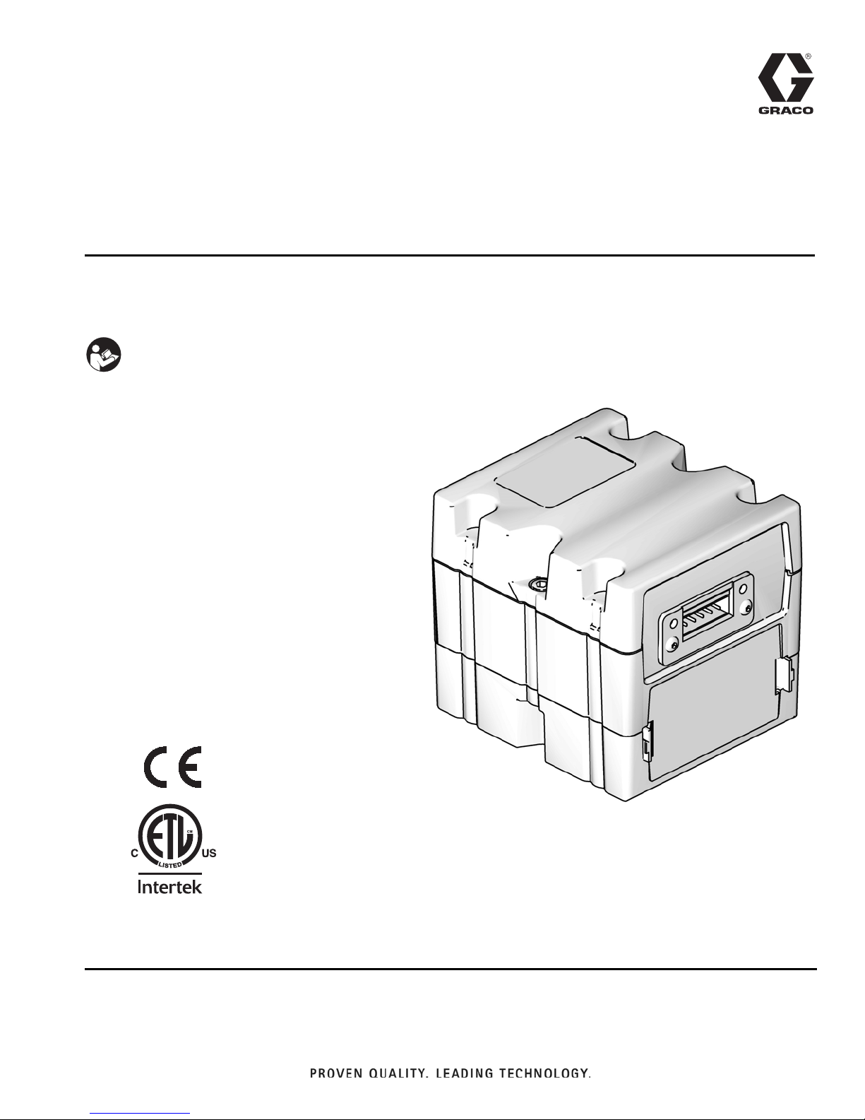
Instructions - Parts
Communications
Gateway Module
For use with Graco Control Architecture based systems to provide fieldbus
communications capabilities.
Important Safety Instructions
Read all warnings and instructions in the system
operation manual. Savetheseinstructions.
312864B
4003764
Conforms to
UL Std. 508
Certified to CAN/CSA Std.
C22.2 No. 14
TI11985A
Page 2
Models
Contents
Models ...................................2
Component Identification ....................3
Overview ..................................4
Installation ................................4
Setup .....................................5
Troubleshooting ...........................10
Parts ....................................11
Technical Data ............................11
Graco Standard Warranty ...................12
Graco Information ........................12
Models
Communications
Gateway Module Part No. Fieldbus
CGMDN0 DeviceNet
CGMEP0 EtherNet/IP
CGMPB0 PROFIBUS
CGMPN0 PROFINET
To order replacement parts, see Parts on page 11.
To order installation kits for a GracoControl Architecture
based system, see the system operation manual.
2 312864B
Page 3
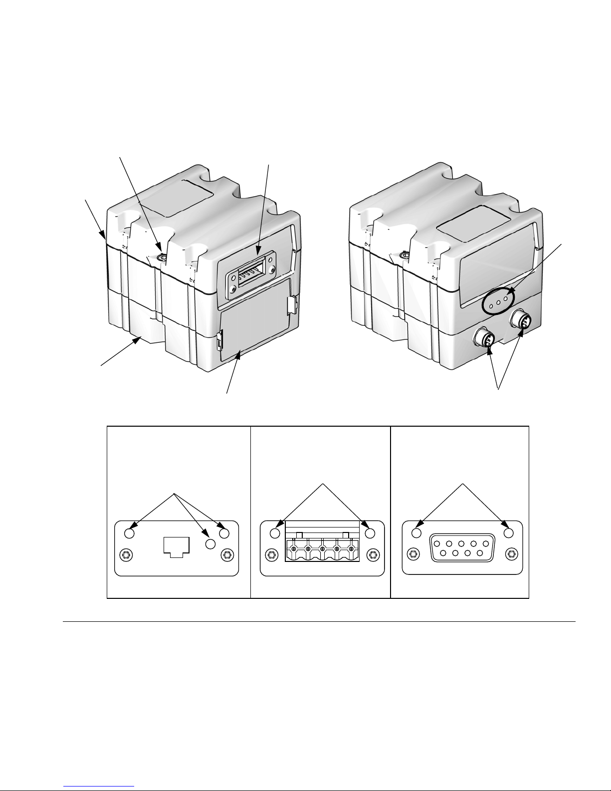
Component Identification
Front Back
D
A
C (see Fieldbus Connector Table)
Component Identification
F
B
E
Fieldbus ConnectorsTable (C)
PROFINET
or
EtherNet/IP
G
TI11814A TI11815A TI11816A
FIG.1:
Key:
A Communications Gateway Module
B Base
C Fieldbus Connector
D Module Connection Screws
E Access Cover
F Module Status LEDs
G Fieldbus Status LEDs (see descriptions on page 6)
H CAN Connectors
TI11985A
DeviceNet
TI11972A
H
PROFIBUS
G G
312864B 3
Page 4
Overview
Overview
Module Description
The Communications Gateway Module (CGM) provides
a control link between Graco ControlArchitecture based
systems and a selected fieldbus.This provides the
means for remote monitoring and control by external
automation systems.
Data provided by the CGM to the fieldbus depends on
which Graco Control Architecture based system and
fieldbus are connected. A data map supplied on a map
token is defined for this pairing. Once the data map has
been loaded into the CGM,it is stored internally,and the
map token is no longer required for operation.
Data Exchange
Data is available by block transfer, cyclic transfer,
change of state triggered, and explicit access to individual attributes as defined by the fieldbus specification.
NOTE:
The following system network configuration files are
available at www.graco.com
Module Requirements
Power Supply
The CGM requires a 12-30 VDC @ 0.2 A power supply.
Refer to the system manual for system level power supply guidelines.
Environment Conditions
Refer to the system manual for guidelines regarding
environment conditions for the CGM.
Installation
The CGM is available for use with all Graco Control
Architecture based systems that have compatible
design. Each CGM requires the following to operate ina
system:
• Mounting hardware
• Map token
• Fieldbus files
• EDS file: DeviceNet or Ethernet/IP fieldbus networks
• GSD file: PROFIBUS fieldbus networks
• SDML: PROFINET fieldbus networks
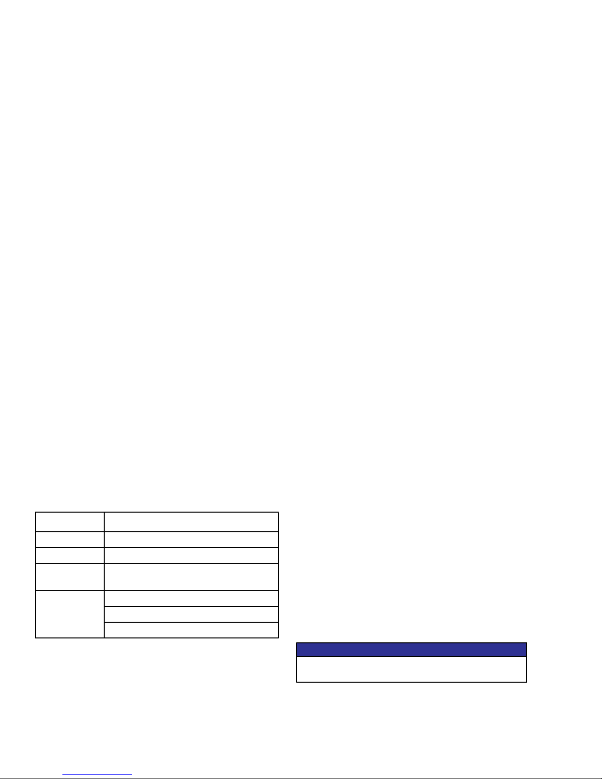
Module Status LED Signals
Signal Description
Green on System is powered up
Yellow Internal communication in progress
Red
Solid
*Red
(7 flashes)
*The red LED (F) will flash a code, pause, then repeat.
See Diagnostic Information on page 10.
NOTE:
Verify that you are using the correct token for your system and reinstall token. If fails, order new token.
CGM hardware failure
Data map load failure
Incorrect data map for fieldbus type
No data map loaded
If your system is compatible for use with a CGM, install
the supplied CGM as explained in the system operation
manual or installation kit manual.
If the CGM is offered only as an accessory for your system, see Accessories in the system operation manual
for available CGM kits.
Connect Cables
If your system is supplied with the CGM and required
components, connect cables as explainedin the system
operation manual.
If the CGM is offered as an accessory for your system,
connect cables as explained in the CGM mounting kit
manual.
NOTICE
Route cables to avoid interference with moving
parts.
4 312864B
Page 5
Setup
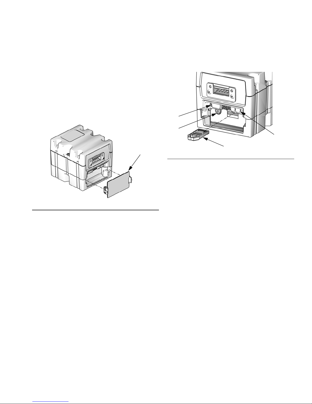
Setup
Install or Update Data Map
NOTE:
The fieldbus connection is temporarily disabled during
the installation or update of a map token.
1. Ensure system is inactive.
2. Remove access cover (E).
E
TI12319A
FIG.2
3. Insert and press map token (T) firmly into slot.
L
S
M
T
FIG.3
4. Press and hold the map upload push button (M) for
three seconds. The red LED (L) will flash twice,
pause, and repeat once after the data map is successfully uploaded. This may take up to 10 seconds.
NOTE:
The rotary switch (S) has no function for the CGM.
TI12320A
5. Remove token (T). Store in a safe place.
6. Replace access cover (E).
312864B 5
Page 6

Setup
Fieldbus Connectors
PROFINET
MS
NS
FIG.4
The Ethernet interface operates at 100Mbit, full duplex, as required by PROFINET. The Ethernet interface is auto
polarity sensing and auto-crossover capable.
Network Status (NS)
State Description Comments
Off Offline - No power
Green On-line, (RUN) - Connection with IO Controller established
Flashing Green On-line, (STOP) - Connection with IO Controller established
Module Status (MS)
State Description Comments
Link
TI11814A
- No connection with IO Controller
- IO Controller with RUN state
- IO Controller in STOP state
Off Not initialized No power or module in “SETUP” or “NW_INIT” state
Green Normal operation Diagnostic event(s) present
Flashing Green Initialized, diagnostic event(s) present Used by engineering tools to identify node on net-
work
Red Exception error Module in state “EXCEPTION”
Red (1 flash) Configuration error Expected Identification differs from Real Identifica-
tion
Red (2 flashes) IP Address not set Set IP address via system monitor or DNS server
Red (3 flashes) Station Name not set Set Station Name via system monitor
Red (4 flashes) Major Internal Error Cycle system power; replace module
Link/Activity (Link)
State Description
Off No Link, no communication present
Green Link established, no communication present
Green, flashing Link established, communication present
6 312864B
Page 7

EtherNet/IP
Setup
MS
Link
TI11814A
IG.5
F
NS
The Ethernet interface operates at 100Mbit, full duplex, as required by PROFINET. The Ethernet interface is auto
polarity sensing and auto-crossover capable.
Network Status (NS)
State Description
Off No power or no IP address
Green On-line, one or more connections established (CIP Class 1 or 3)
Flashing Green On-line, no connections established
Red Duplicate IP address, FATAL error
Flashing Red One or more connections timed out (CIP Class 1 or 3)
Module Status (MS)
State Description
Off No power
Green Controlled by a Scanner in Run state
Flashing Green Not configured, or Scanner in Idle state
Red Major fault (EXCEPTION-state, FATAL error etc.)
Flashing Red Recoverable fault(s)
LINK/Activity (Link)
State Description
Off No link, no activity
Green Link established
Flashing Green Activity
312864B 7
Page 8

Setup
DeviceNet
NS
MS
23451
TI11815A
DC
FIG.6
Network Status (NS)
State Description
Off Not online / No power
Green On-line, one or more connections are established
Flashing Green
On-line, no connections established
(1 Hz)
Red Critical link failure
Flashing Red (1 Hz) One or more connections timed-out
Alternating Red/Green Self test
Module Status (MS)
State Description
Off No power or not initialized
Green Initialized
Flashing Green (1 Hz) Missing or incomplete configuration, device needs com-
missioning
Red Unrecoverable Fault(s)
Flashing Red (1 Hz) Recoverable Fault(s)
Alternating Red/Green Self test
DeviceNet Connector (DC)
Pin Signal Description
1 V- Negative bus supply voltage
2 CAN_L CAN low bus line
3 SHEILD Cable shield
4 CAN_H CAN high bus line
5 V+ Positive bus supply voltage
8 312864B
Page 9

PROFIBUS
Setup
OP
12345
DC
9876
FIG.7
Operation Mode (OP)
State Description
Off Not online / No power
Green On-line, data exchange
Flashing Green On-line, clear
Flashing Red
Parameterization error
(1 flash)
Flashing Red
PROFIBUS Configuration error
(2 flashes)
Status Mode (ST)
ST
TI11816A
State Description
Off No power or not initialized
Green Initialized
Flashing Green Initialized, diagnostic event(s) present
Red Exception error
PROFIBUS Connector (DC)
Pin Signal Description
1- 2- 3 B Line Positive RxD/TxD, RS485 level
4 RTS Request to send
5 GND Bus Ground (isolated)
6 +5V Bus Output +5V termination power (isolated)
7- 8 A Line Negative RxD/TxD, RS485 level
9- Housing Cable Shield Internally connected to the Anybusprotective earth via
cable shield filters according to the PROFIBS standard.
312864B 9
Page 10

Troubleshooting
Troubleshooting
Diagnostic Information
Module Status LED Signal Diagnosis Solution
Red (7 flashes) Data map load failure Verify that you are using the correct
Incorrect data map for fieldbus type
No data map loaded
The red LED (F) will flash a code, pause, then repeat.
token for your system type and reinstall token. If installation fails, order
new token.
10 312864B
Page 11
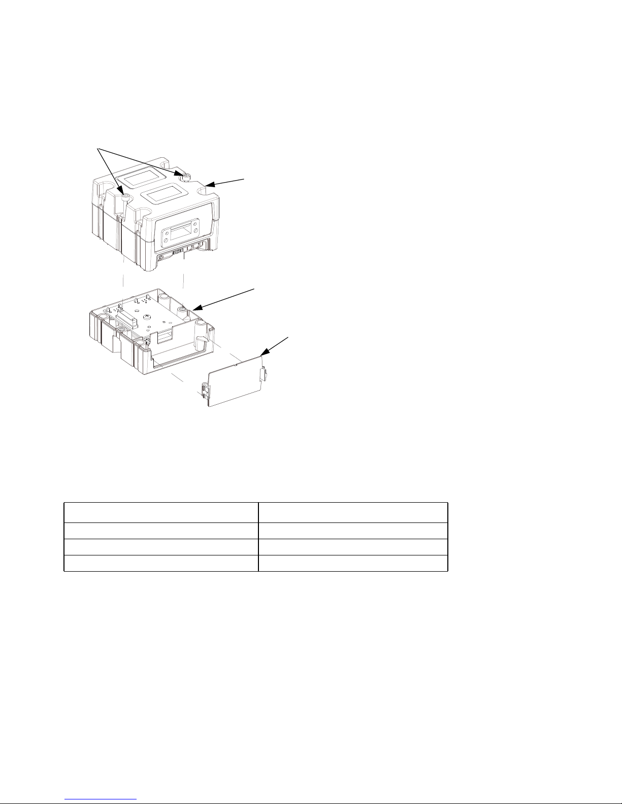
Parts
CGMPB0, CGMPN0, CGMEP0, CGMDN0
Parts
D
Parts
Qty
A
B
E
Ref Part No. Description
A 15V759 MODULE, Gateway,
DeviceNet; CGMDN0 only
15V760 MODULE, Gateway,
EtherNet/IP; CGMEP0 only
15V761 MODULE, Gateway,
PROFIBUS; CGMPB0 only
15V762 MODULE, Gateway,
PROFINET; CGMPN0 only
B 289697 Base 1
D 114135 SCREW, mounting, module connec-
tion
E 277674 COVER, access 1
.
1
1
1
1
2
Technical Data
Category Data
Power requirements 12-30 VDC @ 0.2 A
Weight 12.8 oz.
Dimensions 4.3 in. x 3.8 in. x 3.8 in.
312864B 11
Page 12

Graco StandardWarranty
Graco warrants all equipment referencedinthisdocumentwhichismanufactured by Graco and bearing its name to be free from defects in
material and workmanship on the date of sale to the original purchaser for use. With the exception of any special, extended, or limited warranty
published by Graco, Graco will, for a period of twelve months from the date of sale, repair or replace any part of the equipment determined by
Graco to be defective. This warranty applies only when the equipment is installed, operated and maintained in accordance with Graco’s written
recommendations.
This warranty does not cover, and Graco shall not be liable for general wearandtear, or any malfunction, damage or wear caused by faulty
installation, misapplication, abrasion, corrosion, inadequate or improper maintenance, negligence, accident, tampering, or substitution of
non-Graco component parts. Nor shall Graco be liable for malfunction, damage or wear caused bytheincompatibilityofGraco equipment with
structures, accessories, equipment or materials not supplied by Graco, or the improper design, manufacture, installation, operation or
maintenance of structures, accessories, equipment or materials not supplied by Graco.
This warranty is conditioned upon the prepaid return of the equipment claimed to be defective to an authorized Graco distributor for verification of
the claimed defect. If the claimed defectisverified, Graco will repair or replace free of charge any defective parts. Theequipmentwillbereturned
to the original purchaser transportation prepaid. If inspection of the equipment does not disclose any defect in material or workmanship, repairs
will be made at a reasonable charge, which charges mayincludethecostsofparts, labor, and transportation.
THISWARRANTY IS EXCLUSIVE, AND IS IN LIEU OF ANY OTHERWARRANTIES, EXPRESS OR IMPLIED, INCLUDING BUT NOT
LIMITEDTO WARRANTY OF MERCHANTABILITY ORWARRANTY OF FITNESS FOR A PARTICULAR PURPOSE.
Graco’s sole obligation and buyer’s sole remedy forany breach of warranty shall be as set forth above.Thebuyer agrees that no other remedy
(including, but not limited to, incidental or consequential damages for lost profits, lost sales, injury to person or property, or any other incidental or
consequential loss) shall be available. Any action for breach of warranty must be brought within two (2) years of the date of sale.
GRACO MAKES NOWARRANTY, AND DISCLAIMS ALL IMPLIED WARRANTIES OF MERCHANTABILITY AND FITNESS FOR A
PARTICULAR PURPOSE, IN CONNECTION WITH ACCESSORIES, EQUIPMENT, MATERIALS OR COMPONENTS SOLD BUT NOT
MANUFACTURED BY GRACO.These items sold, but not manufactured by Graco (such as electric motors, switches,hose, etc.), are subject to
the warranty, if any, of their manufacturer. Gracowillprovide purchaser with reasonable assistance in making any claim for breach of these
warranties.
In no event willGracobeliable for indirect, incidental, special or consequential damages resulting from Graco supplying equipment hereunder, or
the furnishing, performance, or use of any products or other goods sold hereto, whether due to a breach of contract, breach of warranty, the
negligence of Graco, or otherwise.
FOR GRACO CANADA CUSTOMERS
The Parties acknowledge that they have required that the present document, as well as all documents, notices and legal proceedings entered into,
given or instituted pursuant hereto or relating directly or indirectly hereto, be drawn up in English. Les parties reconnaissent avoir convenu que la
rédaction du présente document sera en Anglais, ainsi que tous documents, avis et procédures judiciaires exécutés, donnés ou intentés, à la suite
de ou en rapport, directement ou indirectement, avec les procédures concernées.
Graco Information
TO PLACE AN ORDER, contact your Graco distributor or call to identify the nearest distributor.
Phone: 612-623-6921 orToll Free: 1-800-328-0211 Fax: 612-378-3505
PARA EFETUAR ENCOMENDAS OU PARA ASSISTÊNCIATÉCNICA, contate o seu distribuidor da Graco.
POUR PLACER UNE COMMANDE OU DEMANDER DU SERVICE, contactez votre distributeur Graco.
PARA REMITIR UN PEDIDO O SOLICITAR SERVICIO, póngase en contacto con el distribuidor de Graco.
All written and visual data contained in this document reflects the latest product information available at the time of publication.
Graco reserves the right to make changes at any time without notice.
International Offices: Belgium, China, Japan, Korea
GRACO INC. AND SUBSIDIARIES • P.O. BOX 1441 • MINNEAPOLIS MN 55440-1441 • USA
Copyright 2008, Graco Inc. All Graco manufacturing locations are registered to ISO 9001.
This manual contains English. MM 312864
Graco Headquarters: Minneapolis
www.graco.com
Revision B - April 2016
 Loading...