

Page 1
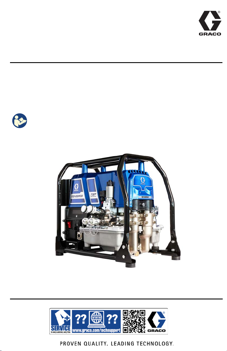
Operation, Repair, Parts
Renegade TSP
3A6884B
Torque Series Pump
Renegade TSP is a hydraulic power pack for use with bolt torquing wrenches only.
For professional use only.
Not approved for use in explosive atmospheres or hazardous (classified) locations.
Models: 17U632, 17U633, 17U634, 17U635
10,000 psi (68.9 MPa, 700 bar) Maximum Working Pressure
Important Safety Instructions
Read all warnings and instructions in this manual and on the unit before using
the equipment. Be familiar with the controls and the proper usage of the
equipment. Save these instructions.
EN
Page 2

Contents
Contents
Contents . . . . . . . . . . . . . . . . . . . . . . . . . . . . . . . . . . . . . . . . . . . . . . . . . . . . . . . . . . 2
Models . . . . . . . . . . . . . . . . . . . . . . . . . . . . . . . . . . . . . . . . . . . . . . . . . . . . . . . . . . . . 3
Warnings . . . . . . . . . . . . . . . . . . . . . . . . . . . . . . . . . . . . . . . . . . . . . . . . . . . . . . . . . . 4
Component Identification . . . . . . . . . . . . . . . . . . . . . . . . . . . . . . . . . . . . . . . . . . . . . 7
Controls and Indicators . . . . . . . . . . . . . . . . . . . . . . . . . . . . . . . . . . . . . . . . . . . . 8
Grounding . . . . . . . . . . . . . . . . . . . . . . . . . . . . . . . . . . . . . . . . . . . . . . . . . . . . . . . . . 9
Power Requirements . . . . . . . . . . . . . . . . . . . . . . . . . . . . . . . . . . . . . . . . . . . . . . 9
Extension Cords . . . . . . . . . . . . . . . . . . . . . . . . . . . . . . . . . . . . . . . . . . . . . . . . . 9
Pressure Relief Procedure . . . . . . . . . . . . . . . . . . . . . . . . . . . . . . . . . . . . . . . . . . . 10
Setup . . . . . . . . . . . . . . . . . . . . . . . . . . . . . . . . . . . . . . . . . . . . . . . . . . . . . . . . . . . . 11
Pendant Setup . . . . . . . . . . . . . . . . . . . . . . . . . . . . . . . . . . . . . . . . . . . . . . . . . . 11
Fill Oil Tank . . . . . . . . . . . . . . . . . . . . . . . . . . . . . . . . . . . . . . . . . . . . . . . . . . . . 11
Modes . . . . . . . . . . . . . . . . . . . . . . . . . . . . . . . . . . . . . . . . . . . . . . . . . . . . . . . . 12
Prime TSP Power Pack Procedure . . . . . . . . . . . . . . . . . . . . . . . . . . . . . . . . . . 12
Connect Hose and Tool . . . . . . . . . . . . . . . . . . . . . . . . . . . . . . . . . . . . . . . . . . . 13
Hose Prime Procedure . . . . . . . . . . . . . . . . . . . . . . . . . . . . . . . . . . . . . . . . . . . 13
Operation . . . . . . . . . . . . . . . . . . . . . . . . . . . . . . . . . . . . . . . . . . . . . . . . . . . . . . . . . 14
Shut Down . . . . . . . . . . . . . . . . . . . . . . . . . . . . . . . . . . . . . . . . . . . . . . . . . . . . . 15
Cleaning . . . . . . . . . . . . . . . . . . . . . . . . . . . . . . . . . . . . . . . . . . . . . . . . . . . . . . 15
Display . . . . . . . . . . . . . . . . . . . . . . . . . . . . . . . . . . . . . . . . . . . . . . . . . . . . . . . . . . . 16
Main Menu Operation . . . . . . . . . . . . . . . . . . . . . . . . . . . . . . . . . . . . . . . . . . . . 16
Change Display Units . . . . . . . . . . . . . . . . . . . . . . . . . . . . . . . . . . . . . . . . . . . . 17
Select Control Device . . . . . . . . . . . . . . . . . . . . . . . . . . . . . . . . . . . . . . . . . . . . 17
Secondary Menu (Stored Data) . . . . . . . . . . . . . . . . . . . . . . . . . . . . . . . . . . . . . 18
Maintenance . . . . . . . . . . . . . . . . . . . . . . . . . . . . . . . . . . . . . . . . . . . . . . . . . . . . . . 19
Recycling and Disposal at End of Life . . . . . . . . . . . . . . . . . . . . . . . . . . . . . . . . 19
Troubleshooting . . . . . . . . . . . . . . . . . . . . . . . . . . . . . . . . . . . . . . . . . . . . . . . . . . . 20
Repair . . . . . . . . . . . . . . . . . . . . . . . . . . . . . . . . . . . . . . . . . . . . . . . . . . . . . . . . . . . . 28
Calibration Procedure . . . . . . . . . . . . . . . . . . . . . . . . . . . . . . . . . . . . . . . . . . . . 28
Pump Removal . . . . . . . . . . . . . . . . . . . . . . . . . . . . . . . . . . . . . . . . . . . . . . . . . 30
Pump Installation . . . . . . . . . . . . . . . . . . . . . . . . . . . . . . . . . . . . . . . . . . . . . . . . 31
2-Way, Poppet Valve Replacement . . . . . . . . . . . . . . . . . . . . . . . . . . . . . . . . . . 32
Pressure Set Valve Replacement . . . . . . . . . . . . . . . . . . . . . . . . . . . . . . . . . . . 33
Pressure Relief Valve Replacement (1,500 and 12,000 PSI) . . . . . . . . . . . . . . 33
4-Way Valve Replacement . . . . . . . . . . . . . . . . . . . . . . . . . . . . . . . . . . . . . . . . 34
Transducer Replacement . . . . . . . . . . . . . . . . . . . . . . . . . . . . . . . . . . . . . . . . . 37
Pendant Battery Replacement . . . . . . . . . . . . . . . . . . . . . . . . . . . . . . . . . . . . . . . . 38
Hydraulic Schematic . . . . . . . . . . . . . . . . . . . . . . . . . . . . . . . . . . . . . . . . . . . . . . . . 39
Wiring Diagram - 120V . . . . . . . . . . . . . . . . . . . . . . . . . . . . . . . . . . . . . . . . . . . . . . 40
Wiring Diagram - 230V . . . . . . . . . . . . . . . . . . . . . . . . . . . . . . . . . . . . . . . . . . . . . . 41
Renegade TSP Torque Series Pump Parts . . . . . . . . . . . . . . . . . . . . . . . . . . . . . . 42
Manifold Assembly Parts . . . . . . . . . . . . . . . . . . . . . . . . . . . . . . . . . . . . . . . . . . . . 44
Motor Assembly Parts . . . . . . . . . . . . . . . . . . . . . . . . . . . . . . . . . . . . . . . . . . . . . . 46
Control Box Parts - 120V . . . . . . . . . . . . . . . . . . . . . . . . . . . . . . . . . . . . . . . . . . . . 48
Control Box Parts - 230V . . . . . . . . . . . . . . . . . . . . . . . . . . . . . . . . . . . . . . . . . . . . 50
Technical Specifications . . . . . . . . . . . . . . . . . . . . . . . . . . . . . . . . . . . . . . . . . . . . 52
Compliance . . . . . . . . . . . . . . . . . . . . . . . . . . . . . . . . . . . . . . . . . . . . . . . . . . . . . . . 53
Radio Frequency Approvals . . . . . . . . . . . . . . . . . . . . . . . . . . . . . . . . . . . . . . . 53
Graco Standard Warranty . . . . . . . . . . . . . . . . . . . . . . . . . . . . . . . . . . . . . . . . . . . 54
Graco Information . . . . . . . . . . . . . . . . . . . . . . . . . . . . . . . . . . . . . . . . . . . . . . . . . . 55
2 3A6884B
Page 3

Models
Models
Model
No. Name Voltage Pendant
17U632
17U633
17U634
17U635
Renegade TSP
Torque Series Pump
Renegade TSP
Torque Series Pump
Renegade TSP
Torque Series Pump
Renegade TSP
Torque Series Pump
120V
120V
230V
230V
Corded 10,000 psi (68.9 MPa, 700 bar)
Wireless 10,000 psi (68.9 MPa, 700 bar)
Corded 10,000 psi (68.9 MPa, 700 bar)
Wireless 10,000 psi (68.9 MPa, 700 bar)
Maximum Working Pressure
psi (MPa, bar)
3A6884B 3
Page 4
Warnings
WARNING
Warnings
The following warnings are for the setup, use, grounding, maintenance, and repair of this
equipment. The exclamation point symbol alerts you to a general warning and the hazard
symbols refer to procedure-specific risks. When these symbols appear in the body of this
manual or on warning labels, refer back to these Warnings. Product-specific hazard symbols
and warnings not covered in this section may appear throughout the body of this manual where
applicable.
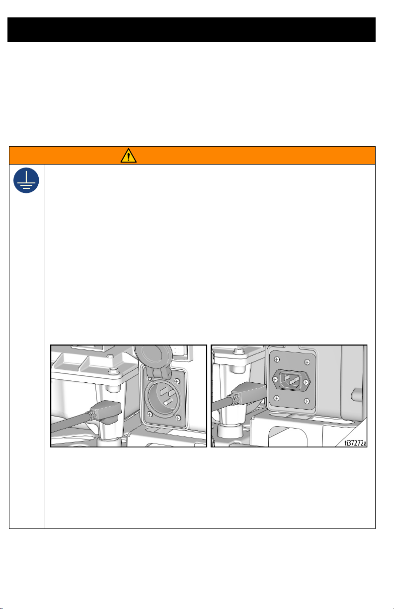
GROUNDING
This product must be grounded. In the event of an electrical short circuit, grounding reduces
the risk of electric shock by providing an escape wire for the electric current. This product is
equipped with an appropriate grounding electrical inlet. This product must be plugged into an
outlet that is properly installed and grounded in accordance with all local codes and regulations.
• Improper installation of the grounding electrical inlet is able to result in a risk of electric
shock.
• When repair or replacement of the electrical inlet is required, do not connect the grounding
wire to either flat blade terminal.
• The wire with insulation having an outer surface that is green with or without yellow stripes
is the grounding wire.
• Check with a qualified electrician or serviceman when the grounding instructions are not
completely understood, or when in doubt as to whether the product is properly grounded.
• Do not modify the electrical inlet. Only connect the product to an extension cord having the
same configuration as the electrical inlet.
• This product is for use on a nominal 120V or 230V circuit and has a grounding electrical
inlet as illustrated in the figure below.
• Do not use a 3-to-2 adapter with this product.
• Extension Cords:
• Use only a 3-wire extension cord that has a grounding plug and a grounding receptacle that
mates with the electrical inlet on the product.
• Make sure your extension cord is not damaged. Use 12 AWG (2.5 mm
the current that the product draws.
2
) minimum to carry
• An undersized cord results in a drop in line voltage and loss of power and overheating.
4 3A6884B
Page 5
Warnings
WARNING
SKIN INJECTION HAZARD
High-pressure leaks are able to inject oil into the body and cause serious bodily injury that can
result in amputation. In the event that injection occurs, get immediate surgical treatment.
• Do not handle pressurized hoses. Escaping oil under pressure can penetrate the skin,
causing serious injury.
• Do not stop or deflect leaks with your hand, body, glove or rag.
• Do not leave the unit energized or under pressure while unattended. When the unit is not
in use, turn off the unit and follow the Pressure Relief Procedure.
• Check hoses and couplings daily. Replace worn or damaged parts immediately.
•
This system is capable of producing 10,000 psi (68.9 MPa, 700 bar). Use Graco replacement
parts or accessories that are rated at a minimum of 10,000 psi (68.9 MPa, 700 bar).
• Verify that all connections are secure before operating the unit.
• Know how to stop the unit and bleed pressure quickly. Be thoroughly familiar with the
controls.
FIRE AND EXPLOSION HAZARD
Flammable fumes in work area can ignite or explode. To help prevent fire and explosion:
• This equipment generates sparks. Do not use in explosive atmospheres or hazardous
(classified) locations.
• Use only in well-ventilated areas.
• Do not plug or unplug power cords, or turn power or light switches on or off, when
flammable fumes are present.
• Keep work area free of debris, including solvent, rags, and gasoline.
• Keep a working fire extinguisher in the work area.
EQUIPMENT MISUSE HAZARD
Misuse can cause death or serious injury.
• Do not operate near children. Keep children away from equipment at all times.
• Do not overreach or stand on an unstable support. Keep effective footing and balance at
all times.
• Stay alert and watch what you are doing.
• Do not leave the unit energized or under pressure while unattended. When the unit is not
in use, turn off the unit and follow the Pressure Relief Procedure.
• Do not operate the unit when fatigued or under the influence of drugs or alcohol.
• Avoid damaging hydraulic hoses. Avoid sharp bends and kinks when routing hydraulic
hoses. Do not kink or over-bend the hose. Using a bent or kinked hose will cause severe
back-pressure. Sharp bends or kinks will cause internal damage to the hose leading to
premature hose failure.
• Do not drop heavy objects on hydraulic hoses. A sharp impact may result in internal
damage to the hose. Applying pressure to a damaged hose may cause it to rupture.
• Do not expose the hose to temperatures or to pressures in excess of those specified by
the hose manufacturer.
• Do not use the hose as a strength member to pull or lift the equipment.
• Do not alter or modify equipment. Alterations or modifications may void agency approvals
and create safety hazards.
• The system operating pressure must not exceed the pressure rating of the lowest rated
piece in the system.
•
Make sure all equipment is rated and approved for the environment in which you are using it.
3A6884B 5
Page 6
Warnings
WARNING
ELECTRIC SHOCK HAZARD
This equipment must be grounded. Improper grounding, setup, or usage of the system can
cause electric shock.
• Turn off and disconnect extension cord before servicing equipment.
• Connect only to grounded electrical outlets.
• Use only 3-wire extension cords.
• Ensure ground prongs are intact on electrical inlet and extension cords.
• Store indoors.
LIFTING HAZARD
This equipment is heavy. To avoid injury, lift using:
• Two persons, or
• A hoist attach to the Lift Point.
MOVING PARTS HAZARD
Moving parts can pinch, cut or amputate fingers and other body parts.
• Keep clear of moving parts.
• Do not operate equipment with protective guards or covers removed.
• Before checking, moving, or servicing equipment, follow the Pressure Relief Procedure
and disconnect all power sources.
PERSONAL PROTECTIVE EQUIPMENT
Wear appropriate protective equipment when in the work area to help prevent serious injury,
including eye injury, hearing loss, inhalation of toxic fumes, and burns. This protective
equipment includes but is not limited to:
• Protective eye wear and hearing protection.
6 3A6884B
Page 7
Component Identification
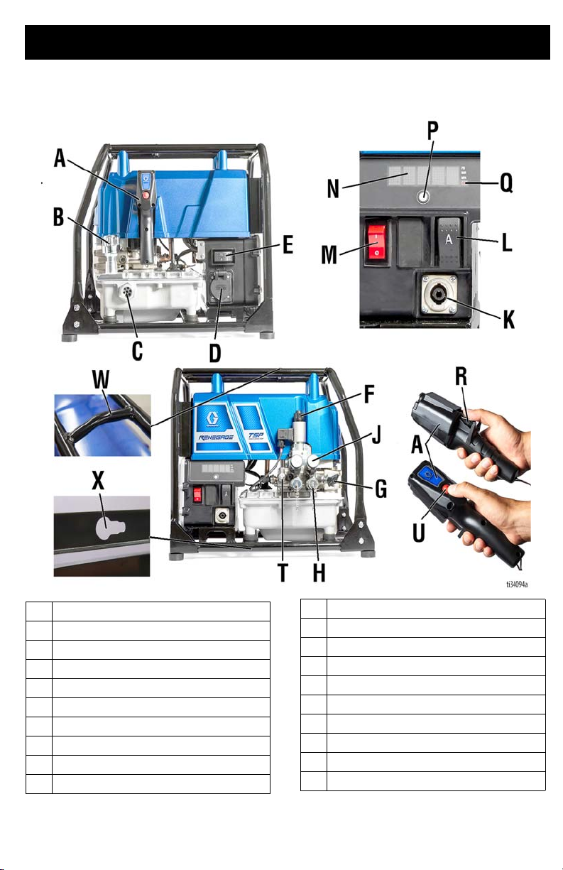
Component Identification
A
Pendant
B
Oil Fill Cap (Breather)
C
Oil Level Sight
D
Electrical Inlet
E
15/20A Switch (120V only)
F
Pressure Relief Button
G
Pressure Setting Valve
H
Hose Connection – Advance
J
Hose Connection – Return
K
Pendant Connector
3A6884B 7
L
Manual Advance Switch
M
On/Off Switch
N
Display
P
Display Button
Q
Wireless Remote Signal Indicator
R
Pendant Advance Switch
T
Pressure Gauge Port
U
Pump Stop Switch
W
Lift Point
X
Pump Rod Puller
Page 8

Component Identification
Controls and Indicators
Item Description
On/Off Switch Turns TSP power pack on or off.
15A/20A Switch
(120V only)
Pressure Setting Valve Controls pressure at the tool. Turn clockwise to increase pressure.
Pressure Relief Button Relieves pressure in the system (pressure goes to zero).
Manual Advance Switch
or Pendant Advance
Switch
Display Shows pressure and other control information.
Display Button Cycles Display through display information.
Pendant Pump Stop
Switch
Sets TSP power pack to either 15A or 20A. Select setting based on
your circuit rating. Select 20A when a 20A circuit is available. Using the
20A setting provides the maximum performance. Select 15A when a
15A circuit is available.
Activates pump to advance the tool when pressed.
Stops pump early if pump stop is needed.
8 3A6884B
Page 9

Grounding
The equipment must be grounded to
reduce the risk of electric shock. Improper
grounding can cause electric shock.
Grounding provides an escape wire for the
electric current.
All electrical wiring must be done by a
qualified electrician and comply with all
local codes and regulations.
Grounding
Power Requirements
100-120 VAC, 50/60 Hz, 15A/20A, single
phase.
220-240 VAC, 50/60 Hz, 10A, single phase.
Extension Cords
Use a 3-wire extension cord with an
undamaged ground contact.
Use a 3-wire, 12 AWG (2.5 mm
extension cord. Longer cords and higher
gauge cords reduce performance.
The plug must be plugged into an outlet that
is properly installed and grounded in
accordance with all local codes and
regulations.
Do not modify plug! If it will not fit in outlet,
have grounded outlet installed by a qualified
electrician. Do not use an adapter.
2
) minimum
3A6884B 9
Page 10
Pressure Relief Procedure
Pressure Relief Procedure
Follow the Pressure Relief
Procedure whenever you see this
symbol.
To help prevent serious injury from
pressurized fluid, such as skin injection,
splashing fluid and moving parts, follow the
Pressure Relief Procedure before
cleaning, checking, or servicing the
equipment.
NOTE: The TSP power pack is designed to
automatically relieve pressure when the
pump motor stops.
1. Verify displayed pressure goes to zero
when motor stops.
2. If pressure is not zero, then press
Pressure Relief Button.
3. Verify pressure has dropped to zero.
4. If you suspect that pressure has not
been fully relieved, rotate the Pressure
Setting Valve counterclockwise until
rotation stops.
10 3A6884B
Page 11
Setup
FULL
Setup
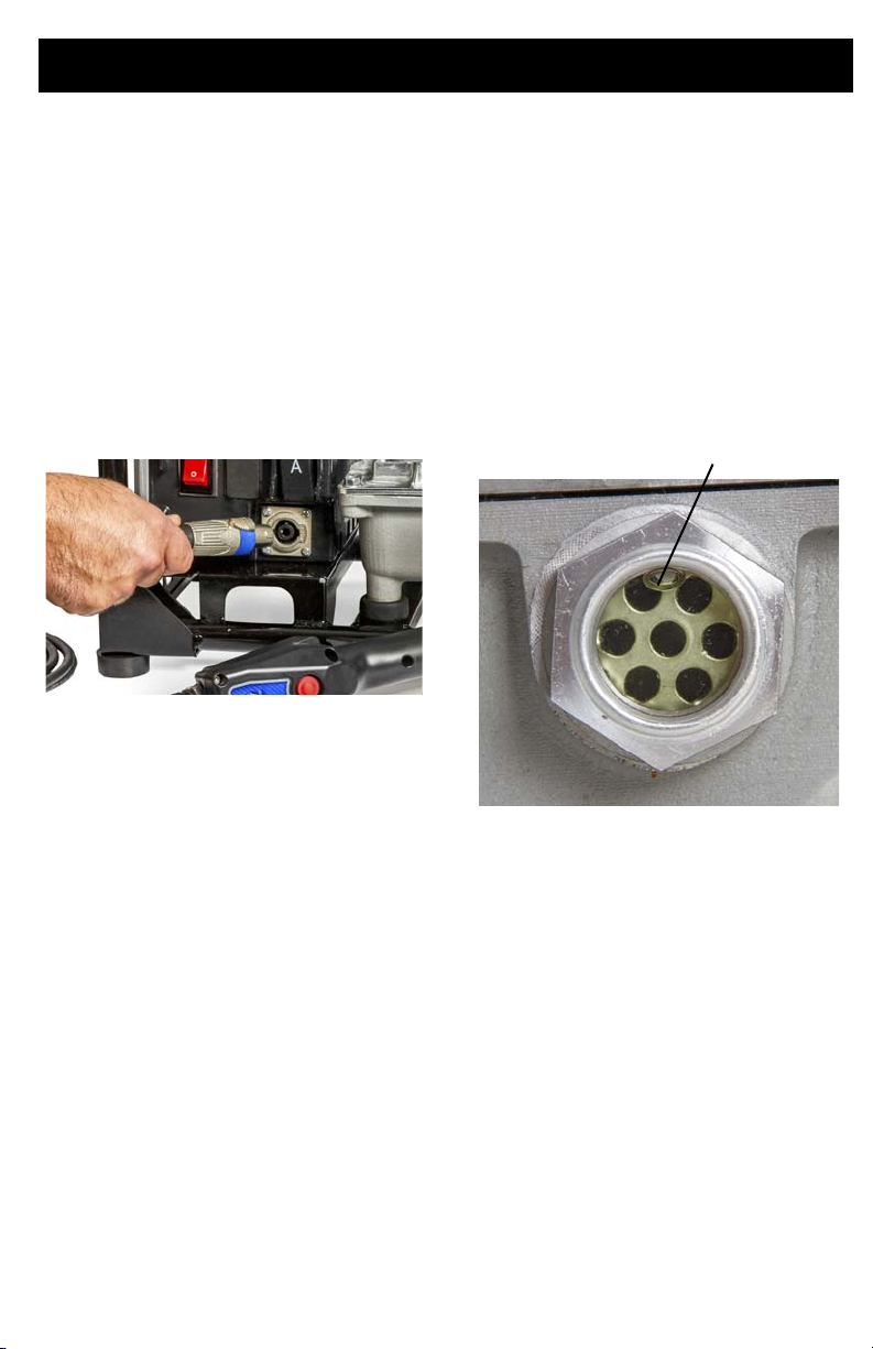
Pendant Setup
Corded Pendant
Attach Corded Pendant by lining up the tab
on the plug with the socket located on the
power pack control. Insert the plug and turn
clockwise until you hear the lock click. The
Corded Pendant must be selected to be the
active control, see Select Control Device
page 17.
Wireless Pendant
The Wireless Pendant must be selected to be
the active control. See Select Control
Device page 17.
Fill Oil Tank
Unit is shipped without hydraulic oil. Before
the first use, fill tank with hydraulic oil, see
Recommended Oil Temperature Ranges
for Various Hydraulic Oil Weights
1. Remove Oil Fill Cap.
2. Add hydraulic oil until oil is visible at the
top of the Sight Glass.
3. Replace Oil Fill Cap.
page 52.
3A6884B 11
Page 12
Setup
Modes
The TSP power pack has three modes:
prime, calibration, and operation.
The prime mode removes air from the pump.
The calibration mode calibrates the
pressure sensor. See Calibration
Procedure page 28.
The operation mode is the normal mode in
which the TSP power pack is ready to torque
bolts.
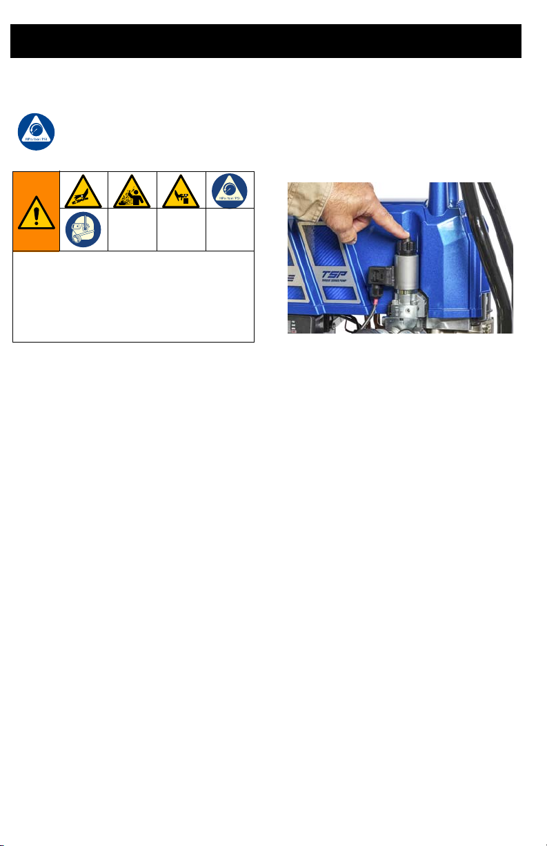
Prime TSP Power Pack Procedure
Priming is required after initial oil fill or pump
replacement. Unit may also require priming
when displayed control pressure reading
fluctuates continuously.
1. Disconnect hoses, if attached.
2. Plug in TSP power pack.
3. Turn ON/OFF switch to ON position.
4. Turn Pressure Setting Valve
counterclockwise until rotation stops.
This is the zero pressure setting.
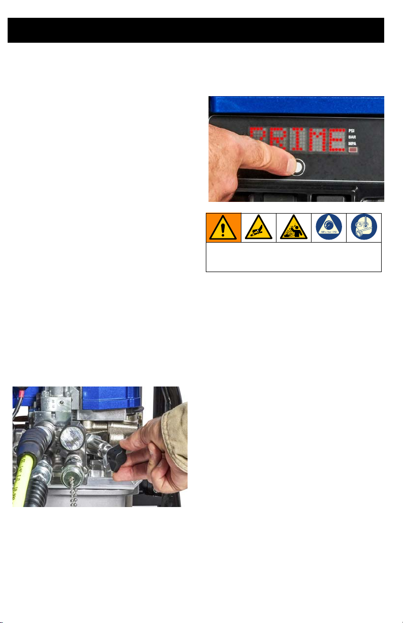
5. Cycle through primary menu by short
pressing the control Display Button until
PRIME appears on Display.
High-pressure leaks are able to inject oil
into the body and cause serious bodily
injury. Do not stop leaks with hand or rag.
6. Press the Advance Switch on selected
control device to start prime mode. 90
will appear on the Display and will count
down in seconds as the prime procedure
automatically occurs.
NOTE: Press Display Button or Pump Stop
Switch any time while in prime mode to
cancel the procedure.
NOTE: TSP power pack will automatically
return to operation mode when prime
procedure is complete.
7. To ensure the TSP power pack is
primed, set pressure to 8000 psi and
press the Advance Switch on selected
control device. The Display pressure
reading should be steady at 8000 +/- 50
psi. If pressure fluctuations are 100 psi or
greater, the Prime TSP Power Pack
Procedure should be repeated.
8. Inspect for leaks. If leaking occurs,
tighten all fittings and repeat the Prime
TSP Power Pack Procedure.
9. Check hydraulic fluid level.
12 3A6884B
Page 13

Setup
Connect Hose and Tool
The TSP power pack uses flush-face
quick-release couplings that are durable and
easy to clean. To connect hose and tool,
follow the steps below.
1. Wipe the mating surfaces of the
couplings on the TSP power pack and
the hoses with a clean rag before making
connection.
2. Connect the hoses from the TSP power
pack to the hydraulic tool.
NOTE: When making connections, do not
over stretch the hoses or bend hoses at a
sharp angle.
Hose Prime Procedure
Prime and flush the hoses each time a hose
is replaced or when swapping tools.
Continuous use of a hose and tool
combination should not require a prime and
flush procedure unless the hoses lose oil.
1. Turn ON/OFF switch to OFF position.
2. Connect hoses to the manifold on the
TSP power pack.
3. Connect hoses together at tool end of
the hose.
4. Turn ON/OFF switch to ON position.
5. Set pressure control to minimum
pressure.
6. Run the TSP power pack for 30 seconds
to purge the air from the hoses.
7. Check hydraulic oil level. Fluid level
should be at the top of the oil level sight
glass. Add oil as needed.
3A6884B 13
Page 14
Operation
Operation
FIRE AND EXPLOSION WARNING
To avoid serious injury, do not use in
explosive atmospheres or hazardous
(classified) locations.
High pressure leaks are able to inject oil
into the body and cause serious bodily
injury. Before each use, inspect hydraulic
lines, fittings, and hoses for breaks,
cracks, worn spots, bulges, kinks and any
other damage. Replace damaged lines,
fittings, or hoses immediately. Never
attempt to repair the damaged parts.
1. Determine desired torque for your
application (nut or bolt specifications
based on the specific project
recommendations or standards
required).
2. Determine desired pump pressure by
referencing wrench specifications for
torque and pressure.
3. Connect hoses and wrench to TSP
power pack. Only use hoses and
wrenches rated at a minimum of 10,000
psi (68.9 MPa, 700 bar).
4. Plug extension cord into TSP power
pack.
AMPUTATION OR CRUSH HAZARD
Unexpected pump activation can cause
serious injury. Ensure hands are clear of
wrench crush points when activating TSP
power pack.
5. Turn ON/OFF switch to ON position.
High-pressure leaks are able to inject oil
into the body and cause serious bodily
injury. Do not stop leaks with hand or rag.
6. Activate TSP power pack with the
selected control device; see Select
Control Device page 17. While holding
Advance Switch, adjust Pressure
Setting Valve until desired pump
pressure is shown on Display or gauge.
NOTE: Inspect for leaks. If leaking occurs,
tighten all fittings and repeat the Prime TSP
Power Pack Procedure page 12.
7. Attach wrench to nut or bolt per wrench
manufacturer’s specifications.
8. Activate TSP power pack by pressing
and holding Advance Switch until end of
wrench stroke. End of stroke is indicated
either by the wrench, the pack pressure
rising rapidly, the nut stopping, or some
combination of these factors.
9. Release Advance Switch and wrench
will automatically return.
10. Repeat steps 8 and 9 until job is
complete.
14 3A6884B
Page 15

Operation
Shut Down
1. Turn ON/OFF switch to OFF position.
Unplug the TSP power pack.
2. Disconnect hoses from TSP power pack.
Cleaning
Proper care and maintenance is
recommended for best experience with the
TSP power pack. For proper maintenance
activity and intervals, see Maintenance page
19.
To clean, wipe TSP power pack and hoses
with a rag to remove any accumulated oil and
dirt after every use.
Wash TSP power pack with mild soap and
water as needed. High pressure washing is
not recommended.
3A6884B 15
Page 16

Display
Display
Main Menu Operation
1. Turn power ON. Display will show
as unit powers on.
2. Once powered on, Display will show
PRESSURE (in PSI, bar, or MPa - as
selected). Refer to Change Display
Units page 17.
3. Short press Display Button and SET
HOURS will scroll past on screen.
NOTE: SET HOURS is a resettable hour
meter that may be used to monitor oil change
intervals.
4. Short press Display Button and
LIFETIME HOURS will scroll past on
screen.
NOTE: LIFETIME HOURS displays a lifetime
hour meter and cannot be reset.
5. Short press Display Button and name of
the selected control device will scroll
past on screen. If no control device is
selected, SELECT CONTROL DEVICE
will scroll past on screen.
a. Press and hold Display Button to
select control device. Refer to
Select Control Device page 17.
6. Short press Display Button and PRIME
will scroll past on screen.
a. Press and hold Display Button to
reset hours to 0.
16 3A6884B
a. Press and Hold Display Button to
enter prime mode. Refer to Prime
TSP Power Pack Procedure page
12.
7. Short press Display Button to return to
PRESSURE screen.
Page 17
Display
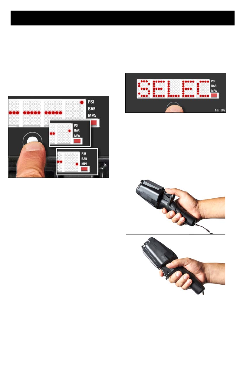
Change Display Units
NOTE: To change display units you must be
in the pressure screen with the pressure
display at zero.
1. Press and hold the Display Button for
5 seconds to change pressure units (psi,
bar, MPa) to desired units. Selection of
bar or MPa changes gallons to liters x 10.
Select Control Device
1. Short press Display Button three times to
move to SELECT CONTROL DEVICE
mode.
2. Press the Advance Switch on desired
control device to select it. Options
available are:
a. Manual Advance Switch.
b. Corded Pendant.
c. Wireless Pendant.
NOTE: The TSP power pack may be paired
with only one control at any time. Any
previously selected devices will be ignored
when a new device is selected.
3A6884B 17
Page 18

Display
Secondary Menu (Stored Data)
NOTE: Secondary Menu contains the
calibration procedure plus information that
may be useful during troubleshooting or
repair.
1. To enter Secondary Menu turn power
switch on while holding Display Button.
Continue to hold Display Button until
CALIBRATE appears.
2. CALIBRATE scrolls past on the Display.
4. Short press Display Button and
SOFTWARE REVISION scrolls past on
the Display.
5. Short press Display Button and LAST
CODE scrolls past on the Display.
a. Press and hold Display Button and
CLEAR will appear for three
seconds on the Display. NO CODE
STORED will then scroll past on
the Display.
a. Press and hold button to enter
CALIBRATION mode. Refer to
Calibration Procedure page 28
for calibration instructions.
b. Short press Display Button to return
3. Short press Display Button and SERIAL
NUMBER scrolls past on the Display.
18 3A6884B
to the CALIBRATE screen.
Page 19

Maintenance
Maintenance
Routine maintenance is important to ensure proper operation of your TSP power pack.
Maintenance includes performing routine actions that keep your TSP power pack in operation
and prevent trouble in the future.
Activity Interval
Inspect pump, hoses, and tools for damage or leaks.
Inspect fan opening for blockage. Daily.
Pressure calibration. Per company, customer, or job
Change hydraulic oil. 40 motor hours.
Recycling and Disposal at End of Life
At the end of the product’s useful life,
dismantle and recycle it in a responsible
manner.
Preparation:
•
Perform the Pressure Relief
Procedure, page 10.
• Drain and dispose of fluids according to
applicable regulations. Refer to the
material manufacturer’s Safety Data
Sheet.
Daily.
specification.
Dismantle and recycle:
•
Remove motors, circuit boards,
displays, and other electronic
components. Remove the battery from
the wireless pendant. Recycle
according to applicable regulations.
• Do not dispose of electronic
components with household or
commercial waste.
• Deliver remaining product to a recycling
facility.
3A6884B 19
Page 20

Troubleshooting
Troubleshooting
1. Follow Pressure Relief Procedure
page 10, before troubleshooting or
repairing TSP power pack.
2. Check all possible problems and causes
before disassembling TSP power pack.
Problem Cause Solution
Unit does not start when plugged in
and power switch is “ON”.
Motor stops under load. Low Voltage. Reset circuit breaker, if tripped.
Blowing circuit breakers. Pump is exceeding circuit
Motor runs but unit will not pump
oil.
Pump does not reach full pressure. Bad transducer. Test with gauge on gauge port to very.
Pump stalls at ~4500 psi. Poppet valve not functioning
Extension cord. Check
extension cord continuity
with ohmmeter.
Low Voltage.
Meter must read: 85-130
VAC (120V),.
Meter must read: 170-260
VAC (240V).
Circuit breaker has tripped. Reset circuit breaker.
breaker rating.
Pump is not primed. Perform Prime TSP Power Pack
Low hydraulic oil level. Add oil see, Fill Oil Tank page 11.
High-pressure pump issue. Replace high-pressure pump. see Pump
Pressure set valve issue. Replace pressure set valve, see
High-pressure relief valve
issue.
4-way valve issue. Replace 4-way valve, see 4-Way Valve
properly.
Replace extension cord.
Reset circuit breaker.
Try another outlet.
Use a heavier gauge extension cord.
Turn off other electric loads.
Use a heavier gauge extension cord.
Make certain that the 15A/20A Switch is
set to the correct position for the circuit
that the unit is plugged in to (120V only).
Set 15A/20A Switch to 15A setting (120V
only).
Procedure page 12.
Replace transducer, see Transducer
Replacement page 37.
Replacement page 30.
Pressure Set Valve Replacement page
33.
Replace high-pressure relief valve, see
Pressure Relief Valve Replacement
(1,500 and 12,000 PSI) page 33.
Replacement page 34.
Replace poppet valve, see 2-Way,
Poppet Valve Replacement page 32.
20 3A6884B
Page 21

Troubleshooting
Problem Cause Solution
Maximum pressure is ~3,300 psi. High pressure pump issue. Replace high pressure pump, see Pump
Unit runs slow. Air in hydraulic system. Check oil level and fill as needed. Perform
Unit set to 15A setting (120V
only).
Hose connection filter
plugged.
Hi-flow pump issue. Replace hi-flow pump, see Pump
High pressure pump issue. Replace high pressure pump, see Pump
4-way valve issue. Replace 4-way valve, see 4-Way Valve
Unit builds full pressure, but torque
wrench fails to advance.
Torque wrench fails to retract. Return flow from wrench is
Pressure indicator does not read
zero (0) psi/bar when pump is
stopped.
TSP power pack does not run at all.
Display shows CODE 03.
Torque is greater than
wrench capacity at full
pressure.
Advance flow line to wrench
is restricted or blocked.
restricted or blocked.
Pressure not relieved. Perform Pressure Relief Procedure
Pressure indicator or gauge
is out of calibration.
Transducer connection
issue (control board is not
detecting a pressure signal).
Replacement page 30.
Prime TSP Power Pack Procedure page
12 and Hose Prime Procedure page 13.
Connect to a 20 Amp circuit and set
switch to 20A setting.
Switch hose connection to other
connectors. Replace filter fitting as
needed.
Replacement page 30.
Replacement page 30.
Replacement page 34.
Use a torque wrench with a larger
capacity.
Check hose couplers for full engagement.
Check hose couplers for full engagement.
page 10.
Replace pressure transducer or
recalibrate with Calibration Procedure
page 28.
1. Set TSP power pack to OFF and
disconnect power to TSP power
pack.
2. Check transducer connection.
3. Disconnect transducer from
connector. Check to see if transduce r
contacts are clean and secure.
4. Reconnect transducer and
connector. Connect power, turn TSP
power pack ON and press Advance
Switch. If TSP power pack does not
run, set TSP power pack to OFF and
proceed to next step.
5. Connect a confirmed working
transducer to transducer connector.
6. Turn TSP power pack ON and press
Advance Switch. If TSP power pack
runs, install new transducer. Replace
control board if TSP power pack does
not run.
3A6884B 21
Page 22

Troubleshooting
Problem Cause Solution
TSP power pack does not run at all.
Display shows CODE 04.
Control board detected
voltage surges.
1. Set TSP power pack to OFF and
disconnect power to TSP power
pack.
2. Locate a good voltage supply to
prevent damage to electronics.
TSP power pack does not run at all.
Display shows CODE 05.
Control is commanding
motor to run, but motor shaft
does not rotate.
1. Remove pumps and try to run TSP
power pack. If motor runs, check for
locked or frozen pump or dr ive train. If
TSP power pack does not run,
continue to step 2.
2. Set TSP power pack to OFF and
disconnect power to TSP power
pack.
3. Remove top half of shroud frame and
shroud.
4. Set TSP power pack to OFF and spin
pump crank 1/2 turn. Restart TSP
power pack. If TSP power pack runs,
replace control board. If TSP power
pack does not run, continue to step 5.
5. Set TSP power pack to OFF and
disconnect power to TSP power
pack.
6. Open control box by removing 8
screws that attach control assembly
to control box. Locate motor
connector (large 6-pin connector)
and disconnect.
7. Perform Spin Test: Test at large
6-pin motor field connector. Test
motor by placing a jumper across pins
1 & 2. Rotate motor fan at about 2
revolutions per second. A cogging
resistance to motion should be felt at
the crank. The motor should be
replaced if no resistance is felt.
Repeat for pin combinations 1 & 3
and 2 & 3. Pin 4 (the green wire) is not
used in this test. If all spin test is
positive, continue to step 6 (see
connections below).
22 3A6884B
Page 23

Troubleshooting
Problem Cause Solution
3A6884B 23
Page 24

Troubleshooting
Resistance Table:
TSP Power Pack 0 ohms
Problem Cause Solution
TSP power pack does not run at all.
Display shows CODE 05.
Control is commanding
motor to run, but motor shaft
does not rotate.
8. Perform Field Short Test: Test at
large 6-pin motor field connector.
There should not be continuity from
pin 4, the ground wire, and any of the
remaining pins. If motor field
connector tests fail, replace motor.
9. Check Motor Thermal Switch:
Unplug thermal wires. Set meter to
ohms. Meter should reach the proper
resistance across pins 5 & 6.
24 3A6884B
Page 25

Problem Cause Solution
Resistance Table:
TSP Power Pack 0 ohms
TSP power pack does not run at all.
Display shows CODE 06.
Troubleshooting
Motor overheated. Note: Motor must be cooled down for the
test.
1. Keep TSP power pack in cooler
location with good ventilation. Make
sure motor air intake is not blocked.
2. Set TSP power pack to OFF and
disconnect power to TSP power
pack.
3. Open control box by removing 8
screws that attach control assembly
to control box.
4. Check thermal switch inside control
box.
5. Disconnect 6-pin connector. Make
sure contacts are clean and secure.
Measure resistance of the thermal
switch (thermal switch is across pins
5 & 6). If reading is not correct,
replace motor.
6. Check Motor Thermal Switch:
Unplug thermal wires. Set meter to
ohms. Meter should reach the proper
resistance across pins 5 & 6.
7. Reconnect 6-pin connector. Connect
power, turn TSP power pack ON and
press Advance Switch. If TSP power
pack does not run, replace control
board.
3A6884B 25
Page 26

Troubleshooting
Problem Cause Solution
TSP power pack does not run at all.
Display shows CODE 08.
Incoming voltage too low for
TSP power pack operation.
1. Set TSP power pack to OFF and
disconnect power to TSP power
pack.
2. Remove other equipment that uses
the same circuit.
3. Locate a good voltage supply to
avoid damage to electronics.
TSP power pack does not run at all.
Display shows CODE 10.
TSP power pack does not run at all.
Display shows CODE 12.
TSP power pack does not run at all.
Display shows CODE 15.
Control board is over
heating.
Excessive current protection
enabled.
Motor not spinning (no
current to motor).
1. Make sure motor air intake is not
blocked.
2. Make sure fan is securely attached
to motor shaft.
3. Replace control board.
4. Replace motor.
Cycle power on and off.
1. Set TSP power pack to OFF and
disconnect power to TSP power
pack.
2. Remove top half of shroud frame and
shroud.
3. Set TSP power pack to OFF and spin
pump crank 1/2 turn. Restart TSP
power pack. If TSP power pack runs,
replace control board. If TSP power
pack does not run, continue to step 5.
4. Turn power on. If code continues,
replace control board.
26 3A6884B
Page 27

Problem Cause Solution
TSP power pack does not run at all.
Display shows CODE 16.
TSP power pack does not run at all.
Display shows CODE 17.
Motor position sensor not
working.
TSP power pack plugged
into wrong voltage.
Troubleshooting
1. Set TSP power pack to OFF and
disconnect power to TSP power
pack.
2. Open control box by removing 8
screws that attach control assembly
to control box.
3. Disconnect motor position sensors
and inspect for damage at
connectors.
4. Reconnect sensor.
5. Turn power ON. If code continues,
replace motor.
1. Set TSP power pack to OFF and
disconnect power to TSP power
pack.
2. Locate a good voltage supply to avoi d
damage to electronics.
3A6884B 27
Page 28

Repair
Repair
Calibration Procedure
The TSP power pack should be re-calibrated
after replacing the transducer or control
assembly. The TSP power pack should also
be re-calibrated as needed based on your
company’s business practices and if you
suspect the TSP power pack is not operating
correctly.
NOTE: This procedure requires the use of a
high precision calibration gauge or data
acquisition system to be used as a calibration
standard. It is recommended to leave hoses
attached to the TSP power pack while
calibrating.
1. Connect the calibration high precision
gauge or data acquisition system to the
pressure gauge port or one of the
advance ports of the hose distribution
manifold.
2. Power up the TSP power pack, but do
not press the Advance Switch.
3. Make sure that the pressure set valve is
fully relieved and all pressure in the TSP
power pack is relieved; see Pressure
Relief Procedure, page 10. There
should be zero pressure in the TSP
power pack.
4. Enter the secondary menu, see
Secondary Menu (Stored Data) page
18.
5. CALIBRATE scrolls on the Display.
6. Press and hold the Display Button for a
few seconds to start the calibration
procedure. Calibration mode has been
entered when RUN TO 8000 PSI
PRESS DISPLAY BUTTON TO SAVE
scrolls on the Display.
28 3A6884B
Page 29

Repair
7. Press the TSP power pack Advance
Switch. Set pressure to 8000 psi per the
calibration gauge or data acquisition
system. While keeping the power pack
running at 8000 psi, press the Display
Button to lock in the 8000 psi value for
the controller.
NOTE: If calibration procedure is successful,
DONE will display on the screen for three
seconds, and then pack will return to normal
operation mode.
NOTE: If the calibration procedure was
unsuccessful, the following message will
scroll on the Display: CALIBRATION
FAILED. Press Display Button to continue.
Perform Pressure Relief Procedure page
10, then cycle power to the TSP power pack
and retry calibration procedure.
NOTE: If calibration procedure is never
successful, replace pressure transducer; see
Transducer Replacement page 37.
3A6884B 29
Page 30

Repair
Pump Replacement
Tools Required: 13 mm wrench.
Pump Removal
(High flow displacement pump shown)
Pump removal includes disassembling the
pump guard and pump bolts and removing
the pump.
1. Perform Pressure Relief Procedure,
page 10 and disconnect power to the
TSP power pack. Tilt unit 90 degrees
backwards to keep oil from running out
when pump is removed.
2. Remove the pump guard (50) and
retaining bolt (43).
3. Remove pump bolts (qty 6).
4. Slowly slide pump out of the drive
housing. Allow filter to drain into
reservoir during removal.
30 3A6884B
Page 31

Repair
Pump Installation
(High flow displacement pump shown)
Pump installation includes securing the pump
and connecting to the fluid inlet and outlet.
1. Install pump tank o-ring and manifold
seals.
2. Slide pump assembly into drive housing
while ensuring the piston rod head is
properly aligned in the assembly
housing.
Failure to properly align piston rod head into
housing during reassembly could severely
damage the TSP power pack during
operation.
NOTE: Adjust pump rod length with pump rod
puller if needed.
NOTICE
3A6884B 31
Page 32

Repair
3. Attach pump housing to manifold with
four screws and flat washers. Torque
screws to 50-70 in-lbs. (5.6-7.9 N
4. Attach pump housing to reservoir with
two screws and flat washers. Torque to
20-25 ft-lbs (27.1-33.4 N•m).
5. Replace pump guard (50) with retaining
bolt (43).
•m).
2-Way, Poppet Valve Replacement
Tools Required: Phillips screwdriver, 7/8 in.
wrench, 3/4 in. wrench.
1. Perform Pressure Relief Procedure,
page 10 and disconnect power to the
TSP power pack.
2. Remove top half of frame and shroud.
3. Completely loosen Phillips screw from
terminal. Remove the terminal.
4. Remove top 3/4 in. top retaining nut and
discard.
32 3A6884B
Page 33

Repair
5. Lift the black solenoid to gain clearance
to the 7/8 in. hex on the body of the
poppet valve. Loosen and remove.
6. Install new solenoid valve without the
new 3/4 in. top retaining nut.
7. Torque the 7/8 in. hex to 19-21 ft. lbs
(25.8-28.5 N•m).
8. Reinstall the top 3/4 in. retaining nut,
torque to 4-5 ft. lbs (5.4-6.8 N•m).
9. Reconnect the terminal and tighten
Phillips head screw.
Pressure Set Valve Replacement
Tools Required: 1-1/16 in. wrench.
1. Perform Pressure Relief Procedure,
page 10 and disconnect power to the
TSP power pack.
2. Use a 1-1/16 in. wrench to loosen.
3. Remove plastic protective cap from new
valve. Ensure washer remains on new
valve.
4. Screw in new valve by hand. Tighten to
57-61 ft. lb (77.2-82.7 N
•m).
Pressure Relief Valve Replacement (1,500 and 12,000 PSI)
Tools Required: 16 mm wrench.
1. Perform Pressure Relief Procedure,
page 10 and disconnect power to the
TSP power pack.
2. Loosen and remove valve with 16 mm
wrench.
3. Replace new valve and torque to 50-55
ft. lbs (67.8-74.6 N
•m).
10. Reinstall shroud and top half of frame.
1,500 psi relief valve shown
3A6884B 33
Page 34

Repair
4-Way Valve Replacement
Tools Required: Phillips screwdriver, 5 mm
Allen wrench, 10 mm wrench.
Remove 4-Way Valve
1. Perform Pressure Relief Procedure,
page 10 and disconnect power to the
TSP power pack.
2. Remove top half of frame and shroud.
4. Remove finger-tight nut on top of valve.
Remove coil from valve.
5. Use a 5 mm Allen wrench to remove the
four M6 screws that secure the 4-Way
Valve to the diverter block. Remove the
4-way valve. Save the M6 screws for
reuse later.
3. Using a Phillips screwdriver, fully loosen
retainer screw. Pull plug off from the
valve.
34 3A6884B
Page 35

Repair
6. Use a 5 mm Allen wrench to remove the
three M6 screws that secure the diverter
block to the manifold. Remove the
diverter block.
7. Make certain the old o-rings are
removed from the manifold.
NOTICE
Failure to remove existing o-rings from
manifold could result in equipment damage
if multiple o-rings are re-installed into the
valve manifold upon reassembly.
Install 4-Way Valve
1. Remove finger-tight nut on top of new
valve. Remove coil from new valve.
2. Using a 5 mm Allen wrench, carefully
separate the 4-way valve from the
diverter block. Ensure o-rings remain in
place on 4-way valve. Set valve aside on
a clean surface.
3. To remove the protective cover from the
bottom of the diverter block remove the
three hex nuts. Dispose of the three hex
nuts and protective cover.
3A6884B 35
Page 36

Repair
4. Ensure new o-rings are installed in
diverter block and remain in place.
Position diverter block on the manifold.
Align the three screws in the diverter
block with the corresponding holes in the
manifold. Secure with the three M6
screws. Torque to 6-8 ft-lbs (8.1-10.8
N•m).
5. Reattach coil on to valve. Tighten plastic
nut finger-tight to top of valve.
6. Position the 4-way valve on the diverter
block, it will only fit in one position.
Secure with the four M6 screws. Torque
to 6-8 ft-lbs (8.1-10.8 N•m).
7. Remove and dispose of plastic cover
over the plug on the terminal of new
valve.
8. Attach wire harness into terminal on
4-way valve, secure by tightening the
retaining screw.
36 3A6884B
Page 37

Repair
Transducer Replacement
Tools Required: 15/16 in. wrench.
Remove Transducer
1. Perform Pressure Relief Procedure
page 10 and disconnect power to the
TSP power pack.
2. Lift connector locking tab on transducer
electrical connector.
3. Unplug electrical connector from
transducer.
4. Use 15/16 in. wrench to remove
transducer from the manifold.
Install Transducer
1. Apply sealant to transducer threads.
2. Start threading transducer into the
manifold.
3. Using a 15/16 in. socket, tighten
transducer to 50-55 ft-lbs (68.8-75.6
N•m).
4. Plug electrical connector into the
transducer.
5. Verify proper operation and inspect for
leaks. If leaks are found, stop unit and
re-torque transducer.
6. Perform Calibration Procedure page
28.
3A6884B 37
Page 38

Pendant Battery Replacement
CR123A
BATTERY
Pendant Battery Replacement
38 3A6884B
Page 39

Hydraulic Schematic
Hydraulic Schematic
Ref Part Description Ref Part Description
1 19Y114 KIT, repair, manifold 19 19Y104 PUMP, high pressure
2 19Y107 KIT, valve, 4-way, directional 48 195695 FILTER, fluid
3 19Y110 KIT, valve, manual pressure set 49 19Y214 FITTING, filter, 1/4 NPT male
6 19Y353 VALVE, 2-way, poppet 50 17U673 FITTING, QD, male, high
7 19Y108 KIT, transducer, high pressure 54 19Y113 KIT, manifold, distribution
8 17U675 VALVE, pressure relief, 1500 psi 56 17U671 FITTING, QD, female, high
9 17U685 VALVE, pressure relief, 12000
10 17Z470* VALVE, check, high pressure 81 19Y215 FITTING, filter, 1/4 NPT female
11 17U703 RESERVOIR, machined
18 19Y106 PUMP, high flow * Included in kit 19Y114
psi
73 17U696 COOLER, oil
pressure
pressure
3A6884B 39
Page 40

Wiring Diagram - 120V
See Control Box Parts 120V page 48 for 120V
control box wiring
Wiring Diagram - 120V
Ref Part Description Ref Part Description
1 19Y111 KIT, motor, hydraulic power
2 19Y107 KIT, valve, 4-way, directional 27 17U610 BOX, control (120V)
6 19Y353 VALVE, 2-way, poppet 74 19Y115 ASSEMBLY, control
7 19Y108 KIT, transducer, high pressure 79 17U625 HARNESS, main, w/ strain relief
13 17S588 WIRE, green, 16 AWG 8”, #10,
22 17U721 FAN, oil cooler (120V)
40 3A6884B
pack
serrated
26 120660 SWITCH, rocker
85 17U743 ANTENNA, RF
Page 41

Wiring Diagram - 230V
See Control Box
Parts - 230V page
50 for 230V control
box wiring
Wiring Diagram - 230V
Ref Part Description Ref Part Description
1 19Y111 KIT, motor, hydraulic power
2 19Y107 KIT, valve, 4-way, directional 27 17U629 BOX, control (230V)
6 17U666 Valve, 2-way, poppet 74 19Y115 ASSEMBLY, control
7 19Y10 KIT, transducer, high pressure 79 17U625 HARNESS, main, w/ strain relief
13 17S588 WIRE, green, 16 AWG 8”, #10,
22 18B723 FAN, oil cooler (230V)
pack
serrated
26 120660 SWITCH, rocker
85 17U743 ANTENNA, RF
3A6884B 41
Page 42

Renegade TSP Torque Series Pump Parts
Ref. Torque Ref. Torque Ref. Torque
20-25 ft-lbs (27.1-33.4 N•m) 30-40 in-lbs (3.4-4.5 N•m) 110-120 in-lbs
(12.4-13.6 N•m)
40-45 in-lbs (5.1-6.2 N•m) 10-12 in-lbs (1.1-1.4 N•m)
95-105 in-lbs
(10.7-11.9 N•m)
40-45 in-lbs (4.5-5.1 N•m)
513249191021
Renegade TSP Torque Series Pump Parts
42 3A6884B
Page 43

Renegade TSP Torque Series Pump Parts
Renegade TSP Torque Series Pump Parts List
Ref. Part Description Qty.
1 19Y111 KIT, motor, hydraulic
power pack
14 100132 WASHER, flat 8
15 119695 DAMPENER, engine
mount
16 19Y252 FRAME, bottom,
painted
19 19Y251 LABEL, pendant 1
22 17U721 FAN, oil cooler, 120V 1
23 17U722 GUARD, 1
24 17U723 SCREW, shcs, m4 x
70mm
25 108768 SCREW, M8, , cap,
hex head
26 104541 NUT, lock 4
28 17Z490 BUMPER 4
29 131327 BOLT, flange head,
serrated, 1/4
36 18A977 SCREW, hex, hd 4
37 124709 SCREW, hex hd,
flange
38 100718 WASHER 1
39 17Z459 SCREW, grounding 1
45 17U752 COVER, motor,
painted
46 17U745 FRAME, top, painted 1
1
4
1
2
4
4
4
1
Ref. Part Description Qty.
61 PENDANT, complete
61a 18A681 MAGNET, lanyard 1
61b 24F260 KIT, battery cap w/
66 17U756 LABEL, brand 1
67 17U757 LABEL, warning, EN,
70 124757 SCREW, M8x40 2
73 17U696 COOLER, oil 1
89 17U682 LABEL, brand, side 1
96 19Y147 LABEL, operator,
97 19Y369 WIRE, jumper, green 1
99 114993 SCREW, mach, pan
100 105689 NUT, machine hex 1
Replacement safety labels, tags, and cards are
available at no cost.
19Y103 WIRED 1
19Y102 WIRELESS includes
CR123A battery
O-ring
FR, ES
(120V models)
19Y577 LABEL, warning
(230V models)
pendant
wash hd
1
1
1
1
1
2
3A6884B 43
Page 44

Manifold Assembly Parts
Ref. Torque Ref. Torque
50-55 ft-lbs (68.8-75.6 N•m) 6-8 ft-lbs (8.1-10.8 N•m)
57-61 ft-lbs (77-83 N•m) 19-21 ft-lbs (25.8-28.5 N•m)
4-5 ft-lbs (5.4-6.8 N•m)
17284
Manifold Assembly Parts
44 3A6884B
Page 45

Manifold Assembly Parts List
7
Ref. Part Description Qty.
1 19Y114 KIT, repair, manifold 1
2 19Y107 KIT, valve, 4-way,
3 19Y110 KIT, valve, manual,
6 19Y353 VALVE, 2-way,
7 19Y108 KIT, transducer, high
8 17U675 VALVE, pressure
9 17U685 VALVE, pressure
10† 19Y593 KIT, repair, valve,
10a 17Z470 VALVE check,
10b 17U662 GASKET, plug 1
10c 17U661 PLUG, body 1
18 19Y418 LABEL, pressure
49 19Y214 FITTING, filter, 1/4
50 17U673 FITTING, qd, male,
51 17U674 FITTING, qd, cap 2
directional
pressure set
poppet
pressure
relief, 1500 PSI
relief, 12000 PSI
check, hp
high-pressure
control
NPT male
high pressure
1
1
1
1
1
1
2
1
1
1
2
Manifold Assembly Parts
Ref. Part Description Qty.
52† 557897 O-RING, -010, 90d,
53† 104282 O-RING, packing 2
54 19Y113 KIT, manifold,
56 17U671 FITTING, qd, female,
57 17U672 FITTING, qd, plug 2
58* 17Z498 PLUG, pipe 1
59* 110580 SCREW, cap, socket hd4
60* 108050 WASHER, lock, spring 4
81 19Y215 FITTING, filter, 1/4
* Parts included in Kit 19Y113
† Parts included in Kit 19Y114
Parts included in Kit 19Y593
buna
distribution
high pressure
NPT female
8
1
2
1
3A6884B 45
Page 46

Motor Assembly Parts
Ref. Torque Ref. Torque Ref. Torque
190-210 in-lbs
(21.5-23.7 N•m)
95-105 in-lbs
(10.7-11.9 N•m)
10-12 in-lbs (1.1-1.4 N•m)
20-25 ft-lbs (27.1-33.4 N•m) 5-7 ft-lbs (6.8-9.5 N•m) 40-45 ft-lbs (54.2-61.0 N•m)
50-70 in-lbs (5.6-7.9 N•m) 145-155 in-lbs
(16.4-17.5 N•m)
57-61 ft-lbs (77-83 N•m)
155-175 in-lbs (5.6-6.8 N•m) 30-40 in-lbs (3.4-4.5 N•m)
45-55 in-lbs (5.1-6.2 N•m) Cranks to be assembled 180°
out of phase
4
10
19
51123
6
12
26
7139
14
Motor Assembly Parts
46 3A6884B
Page 47

Motor Assembly Parts List
Motor Assembly Parts
Ref. Part Description Qty.
1 19Y111 KIT, motor, hydraulic
power pack
2 116074 WASHER, thrust 2
3 107434 BEARING, thrust 2
4 19Y112 KIT, crank, assembled 2
5 17J166 BEARING, thrust 2
6 17U652 HOUSING, drive,
complete
8 17U699 LID, reservoir,
machined
9 17U701 PLATE, diverter,
reservoir
10 17U702 SCREW, fhh, M6 x
20MM
11 17U703 RESERVOIR,
machined
12 17U705 ROD, connecting, high
flow
13 17U707 ROD, connecting, high
pressure
17*† 17U720 O-RING, 128, 70D,
buna
18 19Y106 PUMP, high flow
includes 17, 37, 40, 42,
43, 44, 47, 48, 52, 53,
72
19 19Y104 PUMP, high pressure
includes 17, 37, 41, 42,
43, 44, 47, 48, 52, 53,
72
20 104572 WASHER, lock spring 6
21 117536 SCREW. cap, hex
head
30 17U729 SCREW 4
1
1
1
1
12
1
1
1
2
1
1
6
Ref. Part Description Qty.
31 17U730 FITTING, indicator,
fluid level
32 17U731 CAP, breather, fill 1
33 17U732 O-RING, 382, 70A 1
34 17U733 PLUG, drain 1
37*† 124709 SCREW, hex hd,
flange
40* 17U588 VALVE, inlet check,
high flow
41† 17U606 VALVE, inlet check,
high pressure
42*† 17U593 SUPPORT, inlet
strainer
43*† 107558 SCREW, cap, hex hd 4
44*† 17U744 SCREW, hex, m8 x
55mm
47*† 159346 WASHER 2
48*† 243226 FILTER, fluid 2
52*† 557897 O-RING 5
53*† 104282 O-RING 2
69 17Z489 WASHER, metal,
sealing
71 17S590 GUARD, pump 1
72*† 111003 WASHER, flat 12
75 105676 SCREW, mach, PNH 2
84 17U644 BRACKET, antenna
mount
85 17U743 ANTENNA, RF 1
* Included in Kit 19Y106
† Included in Kit 19Y104
1
7
1
1
2
8
4
1
3A6884B 47
Page 48

Control Box Parts - 120V
Ref. Torque Ref. Torque
10-12 in-lbs (1.1-1.4 N•m) 15-20 in-lbs (1.7-2.3 N•m)
17-21 in-lbs (1.9-2.4 N•m) 40-45 in-lbs (4.5-5.1 N•m)
253
21
Control Box Parts - 120V
48 3A6884B
Page 49

Control Box Parts List
Control Box Parts - 120V
Ref. Part Description Qty.
1 278893 BOX, control, 120V 1
2 17U638 BOARD, assembly,
8 114528 SCREW, mach,
9 17U617 CONNECTOR, power,
10 HARNESS, power 1
17U618 120V
11 17U621 PLATE, backer, power
12 17Z458 STUD, terminal,
13 17S588 WIRE, green, 16 AWG,
14 100166 NUT, full hex 2
15 24Y030 KIT, repair, coil filter,
16 16U215 SCREW, Phillips,
17 17U616 CONNECTOR,
18 17U727 HARNESS, wire,
display
Phillips, PNHD
inlet
240V
connection
ground
8”, #10 serrated
Includes 16
PND, 120V
pendant
board to switches
1
8
1
1
1
1
1
1
1
1
Ref. Part Description Qty.
19 17U620 PLATE, backer,
20 19Y411 COVER, connector 1
22 17U645 SEAL, panel 4
23 17U614 SWITCH, rocker,
24 17U615 SWITCH, two position,
25 17U613 PLUG, hole 1
26 120660 SWITCH, rocker, I/O 1
74 19Y115 CONTROL, assembly,
75 105676 SCREW, mach, PNH 13
76 114391 SCREW, grounding 1
77 17U623 BRACKET, wire 1
78 17U622 WASHER, fender #8 2
79 17U625 HARNESS, main,
88 17U619 LABEL, display 1
pendant connection
advance
15A/20A
120V, Includes 75 and
76
w/strain relief
1
1
1
1
1
3A6884B 49
Page 50

Control Box Parts - 230V
Ref. Torque Ref. Torque
10-12 in-lbs (1.1-1.4 N•m) 15-20 in-lbs (1.7-2.3 N•m)
17-21 in-lbs (1.9-2.4 N•m)
253
Control Box Parts - 230V
50 3A6884B
Page 51

Control Box Parts List
Control Box Parts - 230V
Ref. Part Description Qty.
1 278893 BOX, control, 120V 1
2 17U638 BOARD, assembly,
8 114528 SCREW, mach,
9 17U767 BRACKET, IEC
10 17U637 HARNESS, IEC power
11 17U621 PLATE, backer, power
12 17Z458 STUD, terminal,
13 17S588 WIRE, green, 16 AWG,
14 100166 NUT, full hex 2
15 24W147 BOARD, filter, 230V 1
16 124131 SCREW, mach, pan
17 17U616 CONNECTOR,
display
Phillips, PNHD
connector
inlet
connection
ground
8”, #10 serrated
head
pendant
1
8
1
1
1
1
1
1
1
Ref. Part Description Qty.
18 17U727 HARNESS, wire,
19 17U620 PLATE, backer,
20 19Y411 COVER, connector 1
22 17U645 SEAL, panel 4
23 17U614 SWITCH, rocker,
25 17U613 PLUG, hole 2
26 120660 SWITCH, rocker, I/O 1
74 19Y620 KIT, repair, control
75 105676 SCREW, mach, PNH 13
76 114391 SCREW, grounding 1
77 17U623 BRACKET, wire 1
78 17U622 WASHER, fender #8 2
79 17U625 HARNESS, main,
88 17U619 LABEL, display 1
board to switches
pendant connection
advance
bard, 230V
w/strain relief
1
1
1
1
1
3A6884B 51
Page 52

Technical Specifications
Technical Specifications
Hydraulic Power Pack
US Metric
Pressure
Maximum delivery
Fluid outlet npt
Generator minimum
Motor (brushless DC)
120V, A, Hz
230V, A, Hz
Environmental temperature range -40°–120°F -40°– 49°C
Oil reserve capacity 1 gallon 3.8 liter
Recommended hydraulic oil
Operating oil viscosity range
(centistokes)
Dimensions
Weight (dry) 85 lb 39 kg
Height 17 in. 43 cm
Length 17.75 in. 25 cm
Width 14 in. 36 cm
Ingress Protection
Power pack assembly 44
Pendants 56
Noise (dBa)*
Maximum sound power
Maximum sound pressure
Notes:
*Sound pressure measured 3.1 feet (1 meter) from equipment.
Sound power measured per ISO-3744.
10,000 psi 700 bar, 68.9 MPa
1.7 gpm 6.4 lpm
1/4 in. 1/4 in.
4000 W 4000 W
2 HP 1500 W
20A, 50/60 20A, 50/60
10A, 50/60 10A, 60/60
Grade ISO 10-68
See chart below
94.0 dBa @ 70 psi (0.48 MPa, 4.8 bar)
80.0 dBa @ 70 psi (0.48 MPa, 4.8 bar)
Recommended Oil Temperature Ranges for Various Hydraulic Oil Weights
52 3A6884B
Page 53

Compliance
California Proposition 65
WARNING: This product can expose you to chemicals known to the State of California
to cause cancer and birth defects or other reproductive harm. For more information
go to www.P65Warnings.ca.gov.
Radio Frequency Approvals
Compliance
Transmitter Frequency (all models): 433.92 MHz
Transmitter Power (all models): -9.50 dBm
The enclosed device complies with Part 15 of the FCC Rules and with Industry Canada
license-exempt RSS standard(s). Operation is subject to the following two conditions:(1) this
device may not cause harmful interference and (2) this device must accept any interference
received, including interference that may cause undesired operation.
Changes or modifications not expressly approved by the party responsible for compliance could
void the user’s authority to operate the equipment.
This equipment is not granted protection against harmful interference and cannot cause
interference on systems properly authorized.
NOTE: FCC/IC Notice (all models)
FCC ID: JHICED2
IC: 4840A-CED2
3A6884B 53
Page 54

Graco Standard Warranty
Graco Standard Warranty
Graco warrants all equipment referenced in this document which is manufactured by Graco and bearing
its name to be free from defects in material and workmanship on the date of sale to the original purchaser
for use. With the exception of any special, extended, or limited warranty published by Graco, Graco will,
for a period of twelve months from the date of sale, repair or replace any part of the equipment
determined by Graco to be defective. This warranty applies only when the equipment is installed,
operated and maintained in accordance with Graco’s written recommendations.
This warranty does not cover, and Graco shall not be liable for general wear and tear, or any malfunction,
damage or wear caused by faulty installation, misapplication, abrasion, corrosion, inadequate or
improper maintenance, negligence, accident, tampering, or substitution of non-Graco component parts.
Nor shall Graco be liable for malfunction, damage or wear caused by the incompatibility of Graco
equipment with structures, accessories, equipment or materials not supplied by Graco, or the improper
design, manufacture, installation, operation or maintenance of structures, accessories, equipment or
materials not supplied by Graco.
This warranty is conditioned upon the prepaid return of the equipment claimed to be defective to an
authorized Graco distributor for verification of the claimed defect. If the claimed defect is verified, Graco
will repair or replace free of charge any defective parts. The equipment will be returned to the original
purchaser transportation prepaid. If inspection of the equipment does not disclose any defect in material
or workmanship, repairs will be made at a reasonable charge, which charges may include the costs of
parts, labor, and transportation.
THIS WARRANTY IS EXCLUSIVE, AND IS IN LIEU OF ANY OTHER WARRANTIES, EXPRESS OR
IMPLIED, INCLUDING BUT NOT LIMITED TO WARRANTY OF MERCHANTABILITY OR WARRANTY
OF FITNESS FOR A PARTICULAR PURPOSE.
Graco’s sole obligation and buyer’s sole remedy for any breach of warranty shall be as set forth above.
The buyer agrees that no other remedy (including, but not limited to, incidental or consequential
damages for lost profits, lost sales, injury to person or property, or any other incidental or consequential
loss) shall be available. Any action for breach of warranty must be brought within two (2) years of the
date of sale.
GRACO MAKES NO WARRANTY, AND DISCLAIMS ALL IMPLIED WARRANTIES OF
MERCHANTABILITY AND FITNESS FOR A PARTICULAR PURPOSE, IN CONNECTION WITH
ACCESSORIES, EQUIPMENT, MATERIALS OR COMPONENTS SOLD BUT NOT MANUFACTURED
BY GRACO. These items sold, but not manufactured by Graco (such as electric motors, switches, hose,
etc.), are subject to the warranty, if any, of their manufacturer. Graco will provide purchaser with
reasonable assistance in making any claim for breach of these warranties.
In no event will Graco be liable for indirect, incidental, special or consequential damages resulting from
Graco supplying equipment hereunder, or the furnishing, performance, or use of any products or other
goods sold hereto, whether due to a breach of contract, breach of warranty, the negligence of Graco, or
otherwise.
54 3A6884B
Page 55

Graco Information
Graco Information
For the latest information about Graco products, visit www.graco.com.
For patent information, see www.graco.com/patents.
TO PLACE AN ORDER, contact your Graco distributor or call 1-800-690-2894 to identify the
nearest distributor.
3A6884B 55
Page 56

All written and visual data contained in this document reflects the latest product information available at
Graco reserves the right to make changes at any time without notice.
Original instructions. This manual contains English. MM 3A6884
the time of publication.
Graco Headquarters: Minneapolis
International Offices: Belgium, China, Japan, Korea
GRACO INC. AND SUBSIDIARIES • P.O. BOX 1441 • MINNEAPOLIS MN 55440-1441 • USA
Copyright 2019, Graco Inc. All Graco manufacturing locations are registered to ISO 9001.
www.graco.com
Revision B, January 2020
 Loading...