

Page 1
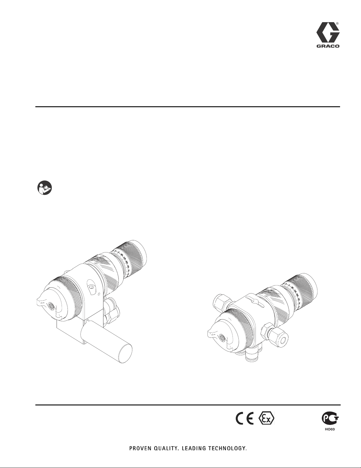
Instructions/Parts
™
AirPro
EFX Automatic
313869B
Spray Gun
Conventional, HVLP, HiTEch, and LVMP automatic guns for small component finishing
applications. For professional use only.
100 psi (0.7 MPa, 7 bar) Maximum Working Fluid Pressure
100 psi (0.7 MPa, 7 bar) Maximum Working Air Pressure
Important Safety Instructions
Read all warnings and instructions in this
manual. Save these instructions.
See page 2 for model information.
ENG
Guns with manifold
TI14428A
TI14427A
Guns without manifold
II 2 G c IIB T6
Page 2

Models
Contents
Models . . . . . . . . . . . . . . . . . . . . . . . . . . . . . . . . . . . 2
Warnings . . . . . . . . . . . . . . . . . . . . . . . . . . . . . . . . . 3
Selection Charts . . . . . . . . . . . . . . . . . . . . . . . . . . . 6
Gun Selection . . . . . . . . . . . . . . . . . . . . . . . . . . . 6
Proper Needle/Nozzle Selection . . . . . . . . . . . . . 6
Models With Manifolds . . . . . . . . . . . . . . . . . . . . 7
Models Without Manifolds . . . . . . . . . . . . . . . . . . 7
Air Caps . . . . . . . . . . . . . . . . . . . . . . . . . . . . . . . 8
Sample Pattern Sizes and Shapes . . . . . . . . . . . 8
Needle Assembly Identification . . . . . . . . . . . . . . 8
Installation . . . . . . . . . . . . . . . . . . . . . . . . . . . . . . . 10
Ventilate Spray Booth . . . . . . . . . . . . . . . . . . . . 10
Configure Gun and Manifold . . . . . . . . . . . . . . . 10
Ground System . . . . . . . . . . . . . . . . . . . . . . . . . 11
Mount Gun . . . . . . . . . . . . . . . . . . . . . . . . . . . . 12
Setup . . . . . . . . . . . . . . . . . . . . . . . . . . . . . . . . . . . . 13
Connect Air Line . . . . . . . . . . . . . . . . . . . . . . . . 13
Connect Fluid Hose . . . . . . . . . . . . . . . . . . . . . 15
Flush Spray Gun . . . . . . . . . . . . . . . . . . . . . . . . 16
Position Air Cap . . . . . . . . . . . . . . . . . . . . . . . . 16
Adjust Spray Pattern . . . . . . . . . . . . . . . . . . . . . 16
Operation . . . . . . . . . . . . . . . . . . . . . . . . . . . . . . . . 18
Pressure Relief Procedure . . . . . . . . . . . . . . . . 18
Apply Fluid . . . . . . . . . . . . . . . . . . . . . . . . . . . . . 18
Daily Gun Care . . . . . . . . . . . . . . . . . . . . . . . . . 19
General System Maintenance . . . . . . . . . . . . . . 20
Clean and Flush Gun . . . . . . . . . . . . . . . . . . . . . 20
Troubleshooting . . . . . . . . . . . . . . . . . . . . . . . . . . . 22
Service . . . . . . . . . . . . . . . . . . . . . . . . . . . . . . . . . . 24
Disassembly . . . . . . . . . . . . . . . . . . . . . . . . . . . 24
Reassembly . . . . . . . . . . . . . . . . . . . . . . . . . . . . 25
Parts . . . . . . . . . . . . . . . . . . . . . . . . . . . . . . . . . . . . 26
Repair Kits . . . . . . . . . . . . . . . . . . . . . . . . . . . . . . . 28
Accessories . . . . . . . . . . . . . . . . . . . . . . . . . . . . . . 28
Dimensions . . . . . . . . . . . . . . . . . . . . . . . . . . . . . . . 29
Mounting Hole Layouts . . . . . . . . . . . . . . . . . . . . . 30
Technical Data . . . . . . . . . . . . . . . . . . . . . . . . . . . . 32
Air Flow . . . . . . . . . . . . . . . . . . . . . . . . . . . . . . . . . . 34
Spray Pattern Test Report . . . . . . . . . . . . . . . . . 35
Graco Standard Warranty . . . . . . . . . . . . . . . . . . . 36
Graco Information . . . . . . . . . . . . . . . . . . . . . . . . . 36
Models
Orifice Size
Spray Type
Conventional
Conventional
Conventional
Conventional
Conventional
HVLP
HVLP
HVLP
HVLP
HiTEch
HiTEch
HiTEch
LV MP
LV MP
LV MP
LV MP
LV MP
LV MP
Air Brush
Gun without needle,
nozzle, or air cap
* Needle tip and nozzle exit constructed from tungsten carbide.
in. (mm)
0.028 (0.7) 24B857 24B877
0.035 (0.9) 24B858 24B878
0.043 (1.1) 24B859 24B879
0.051 (1.3) 24B860 24B880
0.059 (1.5) 24B861* -----
0.020 (0.5) 24B862 -----
0.028 (0.7) 24B863 24B881
0.043 (1.1) 24B864 24B882
0.051 (1.3) 24B865 24B883
0.028 (0.7) 24B866 24B884
0.039 (1.0) 24B867* 24B885*
0.059 (1.5) 24B868* 24B886*
0.020 (0.5) 24B869 24B887
0.028 (0.7) 24B870 24B888
0.035 (0.9) 24B871 24B889
0.043 (1.1) 24B872 24B890
0.051 (1.3) 24B873 24B891
0.059 (1.5) 24B874* -----
0.028 (0.7) 24B875 24B892
N/A 24B876 24B893
Models with
Manifold**
Models without
Manifold
** Models with manifold have fully stainless steel fluid passages.
2 313869B
Page 3
Warnings
Warnings
The following warnings are for the setup, use, grounding, maintenance, and repair of this equipment. The exclamation point symbol alerts you to a general warning and the hazard symbol refers
to procedure-specific risk. Refer back to these warnings. Additional, product-specific warnings
may be found throughout the body of this manual where applicable.
WARNING
FIRE AND EXPLOSION HAZARD
Flammable fumes, such as solvent and paint fumes, in work area can ignite or
explode. To help prevent fire and explosion:
• Use equipment only in well ventilated area.
• Eliminate all ignition sources; such as pilot lights, cigarettes, portable electric
lamps, and plastic drop cloths (potential static arc).
• Keep work area free of debris, including solvent, rags and gasoline.
• Do not plug or unplug power cords, or turn power or light switches on or off when
flammable fumes are present.
• Ground all equipment in the work area. See Grounding instructions.
• Use only grounded hoses.
• Hold gun firmly to side of grounded pail when triggering into pail.
• If there is static sparking or you feel a shock, stop operation immediately. Do not
use equipment until you identify and correct the problem.
• Keep a working fire extinguisher in the work area.
313869B 3
Page 4
Warnings
WARNING
EQUIPMENT MISUSE HAZARD
Misuse can cause death or serious injury.
• Do not operate the unit when fatigued or under the influence of drugs or alcohol.
• Do not exceed the maximum working pressure or temperature rating of the lowest
rated system component. See Technical Data in all equipment manuals.
• Use fluids and solvents that are compatible with equipment wetted parts. See
Technical Data in all equipment manuals. Read fluid and solvent manufacturer’s
warnings. For complete information about your material, request MSDS from distributor or retailer.
• Do not leave the work area while equipment is energized or under pressure. Turn
off all equipment and follow the Pressure Relief Procedure when equipment is
not in use.
• Check equipment daily. Repair or replace worn or damaged parts immediately
with genuine manufacturer’s replacement parts only.
• Do not alter or modify equipment.
• Use equipment only for its intended purpose. Call your distributor for information.
• Route hoses and cables away from traffic areas, sharp edges, moving parts, and
hot surfaces.
• Do not kink or over bend hoses or use hoses to pull equipment.
• Keep children and animals away from work area.
• Comply with all applicable safety regulations.
PRESSURIZED EQUIPMENT HAZARD
Fluid from the gun/dispense valve, leaks, or ruptured components can splash in the
eyes or on skin and cause serious injury.
• Follow the Pressure Relief Procedure when you stop spraying and before clean-
ing, checking, or servicing equipment.
• Tighten all fluid connections before operating the equipment.
• Check hoses, tubes, and couplings daily. Replace worn or damaged parts immedi-
ately.
PRESSURIZED ALUMINUM PARTS HAZARD
Use of fluids that are incompatible with aluminum in pressurized equipment can
cause serious chemical reaction and equipment rupture. Failure to follow this warning
can result in death, serious injury, or property damage.
• Do not use 1,1,1-trichloroethane, methylene chloride, other halogenated hydrocar-
bon solvents or fluids containing such solvents.
• Many other fluids may contain chemicals that can react with aluminum. Contact
your material supplier for compatibility.
4 313869B
Page 5
Warnings
WARNING
TOXIC FLUID OR FUMES HAZARD
Toxic fluids or fumes can cause serious injury or death if splashed in the eyes or on
skin, inhaled, or swallowed.
• Read MSDSs to know the specific hazards of the fluids you are using.
• Store hazardous fluid in approved containers, and dispose of it according to appli-
cable guidelines.
PERSONAL PROTECTIVE EQUIPMENT
You must wear appropriate protective equipment when operating, servicing, or when
in the operating area of the equipment to help protect you from serious injury, including eye injury, hearing loss, inhalation of toxic fumes, and burns. This equipment
includes but is not limited to:
• Protective eyewear, and hearing protection.
• Respirators, protective clothing, and gloves as recommended by the fluid and sol-
vent manufacturer.
313869B 5
Page 6

Selection Charts
Selection Charts
TERMS
Light Fluid: Up to 18 seconds with No. 2 Zahn
cup (20 centipoise)
Medium Fluid:19 to 28 seconds with No. 2
Zahn cup (20-64 centipoise)
Heavy Fluid: Greater than 28 seconds with
No. 2 Zahn cup (greater than 64 centipoise) --
2.8 Volatile Organic Compounds, High-solid
Polyurethanes, Heavy Waterborne Enamels
Gun Selection
HVLP Guns
An HVLP gun is a high transfer efficiency gun
that limits the air pressure at the air cap to
10 psi (0.07 MPa, 0.7 bar) maximum. In some
areas, an HVLP gun is required for compliance
with environmental standards. See the Air Cap
chart, page 8, for maximum inlet pressure.
Proper Needle/Nozzle Selection
The spray gun's needle/nozzle kits range in
size to provide different fluid flow rates. As a
general guideline, use the fluid nozzle that will
give the required flow with the needle fully triggered at a fluid pressure of 5–20 psi
(0.035–0.14 MPa, 0.35–1.4 bar).
• For low flow rates or light viscosity fluid,
select the smaller nozzle sizes.
• For high flow rates or high viscosity fluid,
select the larger nozzle sizes.
• For abrasive fluids, the gun models with
tungsten carbide needle tip and nozzle are
recommended.
Orifice Size
in. mm oz/min cc/min
Viscosity
Flow
LVMP Guns
An LVMP gun is a high transfer efficiency gun
that has been tested to have a transfer efficiency greater than or equal to HVLP guns. In
addition, the LVMP air cap consumes much
less air than the HVLP air cap. Graco LVMP
guns have no restrictions on air cap pressures.
Conventional Guns
A conventional gun has excellent atomization
and high production rates typically with some
reduction in transfer efficiency.
HiTEch Guns
A HiTEch gun is a high transfer efficiency gun
with excellent atomization. Graco HiTEch guns
have no restrictions on air cap pressures.
0.020 0.5 light 0.2-1.7 5-50
0.028 0.7 light 0.3-3.4 10-100
0.035 0.9 light-medium 0.5-5.1 15-150
0.039 1.0 light-medium 0.7-6.8 20-200
0.043 1.1 light-medium 0.8-8.5 25-250
0.051 1.3 medium 1.2-11.8 35-350
0.059 1.5 medium 1.5-15.2 45-450
6 313869B
Page 7

Selection Charts
Models With Manifolds
Includes: Orifice Size
Gun
Assembly
Part No. Type
24B857 Conventional 24D177 24C182 0.028 0.7 Stainless Steel Indexing Plastic
24B858 Conventional 24C198 24C182 0.035 0.9 Stainless Steel Indexing Plastic
24B859 Conventional 24C199 24C182 0.043 1.1 Stainless Steel Indexing Plastic
24B860 Conventional 24C200 24C182 0.051 1.3 Stainless Steel Indexing Plastic
24B861 Conventional 24D178 24C182 0.059 1.5 Carbide Indexing Plastic
24B862 HVLP 24D302 24C183 0.020 0.5 Stainless Steel Indexing Plastic
24B863 HVLP 24D179 24C183 0.028 0.7 Stainless Steel Indexing Plastic
24B864 HVLP 24D305 24C183 0.043 1.1 Stainless Steel Indexing Plastic
24B865 HVLP 24D306 24C183 0.051 1.3 Stainless Steel Indexing Plastic
24B866 HiTEch 24D303 24D703 0.028 0.7 Stainless Steel Ultra Precision Stainless Steel
24B867 HiTEch 24C221 24D703 0.039 1.0 Carbide Ultra Precision Stainless Steel
24B868 HiTEch 24C201 24D704 0.059 1.5 Carbide Ultra Precision Stainless Steel
24B869 LV MP 24D277 24C184 0.020 0.5 Stainless Steel Ultra Precision Plastic
24B870 LV MP 24D278 24C184 0.028 0.7 Stainless Steel Ultra Precision Plastic
24B871 LV MP 24D279 24C184 0.035 0.9 Stainless Steel Ultra Precision Plastic
24B872 LV MP 24D280 24C184 0.043 1.1 Stainless Steel Ultra Precision Plastic
24B873 LV MP 24D281 24C184 0.051 1.3 Stainless Steel Ultra Precision Plastic
24B874 LV MP 24D284 24C184 0.059 1.5 Carbide Ultra Precision Plastic
24B875 Air Brush 24C197 24D705 0.028 0.7 Stainless Steel Indexing Plastic
24B876 N/A N/A N/A N/A N/A N/A Indexing Plastic
Needle/
Nozzle Kit
Part No.
Air Cap
with Pin
Part No. in. mm
Construction
of Needle Tip/
Nozzle Exit
Fluid
Adjustment
Knob
Construction
of Fluid
Fitting
Models Without Manifolds
Includes: Orifice Size
Gun
Assembly
Part No. Type
24B877 Conventional 24D177 24C182 0.028 0.7 Stainless Steel Lock Ring Plastic
24B878 Conventional 24C198 24C182 0.035 0.9 Stainless Steel Lock Ring Plastic
24B879 Conventional 24C199 24C182 0.043 1.1 Stainless Steel Lock Ring Plastic
24B880 Conventional 24C200 24C182 0.051 1.3 Stainless Steel Lock Ring Plastic
24B881 HVLP 24D179 24C183 0.028 0.7 Stainless Steel Indexing Plastic
24B882 HVLP 24D305 24C183 0.043 1.1 Stainless Steel Indexing Plastic
24B883 HVLP 24D306 24C183 0.051 1.3 Stainless Steel Indexing Plastic
24B884 HiTEch 24D303 24D703 0.028 0.7 Stainless Steel Ultra Precision Stainless Steel
24B885 HiTEch 24C221 24D703 0.039 1.0 Carbide Ultra Precision Stainless Steel
24B886 HiTEch 24C201 24D704 0.059 1.5 Carbide Ultra Precision Stainless Steel
24B887 LV MP 24D277 24C184 0.020 0.5 Stainless Steel Indexing Plastic
24B888 LV MP 24D278 24C184 0.028 0.7 Stainless Steel Indexing Plastic
24B889 LV MP 24D279 24C184 0.035 0.9 Stainless Steel Indexing Plastic
24B890 LV MP 24D280 24C184 0.043 1.1 Stainless Steel Indexing Plastic
24B891 LV MP 24D281 24C184 0.051 1.3 Stainless Steel Indexing Plastic
24B892 Air Brush 24C197 24D705 0.028 0.7 Stainless Steel Indexing Plastic
24B893 N/A N/A N/A N/A N/A NA Indexing Plastic
Needle/
Nozzle Kit
Part No.
Air Cap
with Pin
Part No. in. mm
Construction
of Needle Tip/
Nozzle Exit
Fluid
Adjustment
Knob
Construction
of Fluid
Fitting
313869B 7
Page 8
Selection Charts
Air Caps
Nozzle Orifice Recommended
Gun/Manifold
Air Cap
Part No. Type
24C182 Conventional 0.028-0.059 0.7-1.5 43 (0.3, 3.0) Blue-Grey
24C183 HVLP 0.020-0.051 0.5-1.3 15 (0.1, 1.0)* Pewter
24D703 HiTEch 0.028-0.039 0.7-1.0 29 (0.2, 2.0) Black
24D704 HiTEch 0.059 1.5 29 (0.2, 2.0) Black
24C184 LVMP 0.020-0.059 0.5-1.5 43 (0.3, 3.0) Brown
24D705 Air Brush 0.028 0.7 29 (0.2, 2.0) Clear
* Maximum compliant HVLP inlet pressure.
Inlet Pressure
psi (MPa, bar) Air Cap Colorin. mm.
Sample Pattern Sizes and Shapes
Recommended
Nozzle
Air Cap
Part No. Type
24C182 Conventional 0.028 (0.7) 43 (0.3, 3.0) 2.7 (80) 6 (15) Taper 1.0-6.0 (25-152)
24C183 HVLP 0.028 (0.7) 15 (0.1, 1.0) 2.7 (80) 6 (15) Straight 1.0-6.5 (25-165)
24D703 HiTEch 0.028 (0.7) 29 (0.2, 2.0) 2.7 (80) 6 (15) Straight 1.0-6.5 (25-165)
24D704 HiTEch 0.059 (1.5) 29 (0.2, 2.0) 2.7 (80) 6 (15) Straight 1.0-6.5 (25-165)
24C184 LVMP 0.028 (0.7) 43 (0.3, 3.0) 2.7 (80) 6 (15) Straight 1.0-6.5 (25-165)
24D705 Air Brush 0.028 (0.7) 29 (0.2, 2.0) 1.0 (30)
Orifice
in. (mm)
Gun/Manifold
Inlet Pressure
psi (MPa, bar)
Fluid* Flow
Rate
oz/min (cc/min)
Spray
Distance
in (cm)
2 (5)
4 (10) 0.6 (15)
6 (15) 0.7 (19)
Pattern
Shape
Round
Pattern Size*
in. (mm)
0.5 (13)
* Fluid viscosity for these samples was 30 centipoise.
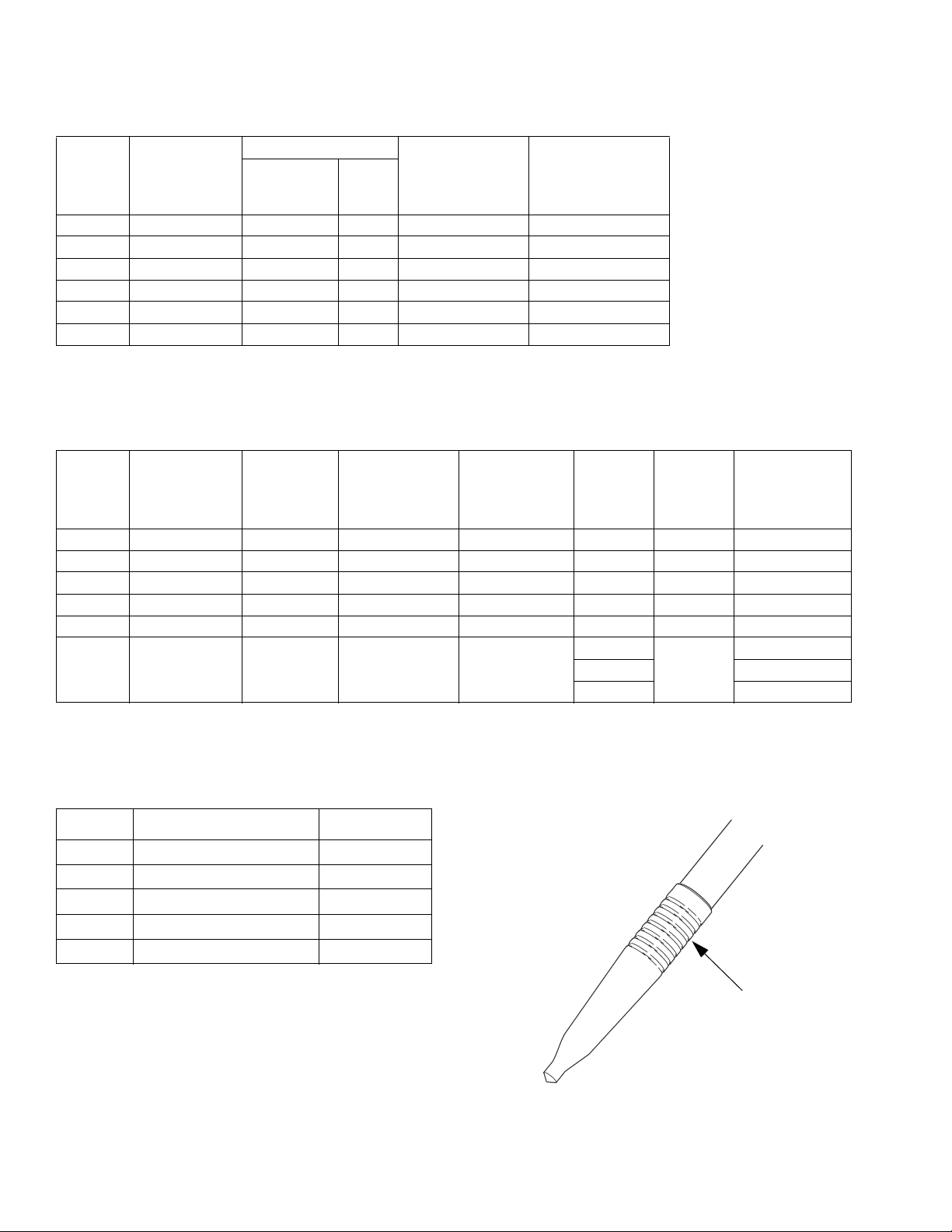
Needle Assembly Identification
Part Needle Assembly Size # of Grooves
24C190 0.5 mm 1
24C191 0.7 mm 2
24C192 0.9 mm 3
24C193 1.1 mm 4
24C194 1.3 mm 5
Grooves
ti14043a
8 313869B
Page 9

Selection Charts
313869B 9
Page 10
Installation
Installation
This spray gun can spray most coatings or finishes currently being used for small component plastic, wood and metal finishing
applications, while easily operating from paint
delivery systems, such as pressure pots or
remote pumps for production line operation.
The air regulator must have a minimum air flow
capacity of 30 scfm at 100 psi (0.7 MPa,
7.0 bar) air pressure.
Ventilate Spray Booth
To prevent hazardous concentrations of toxic
and/or flammable vapors, spray only in a properly ventilated spray booth. Do not operate the
spray gun unless ventilation fans are
operating.
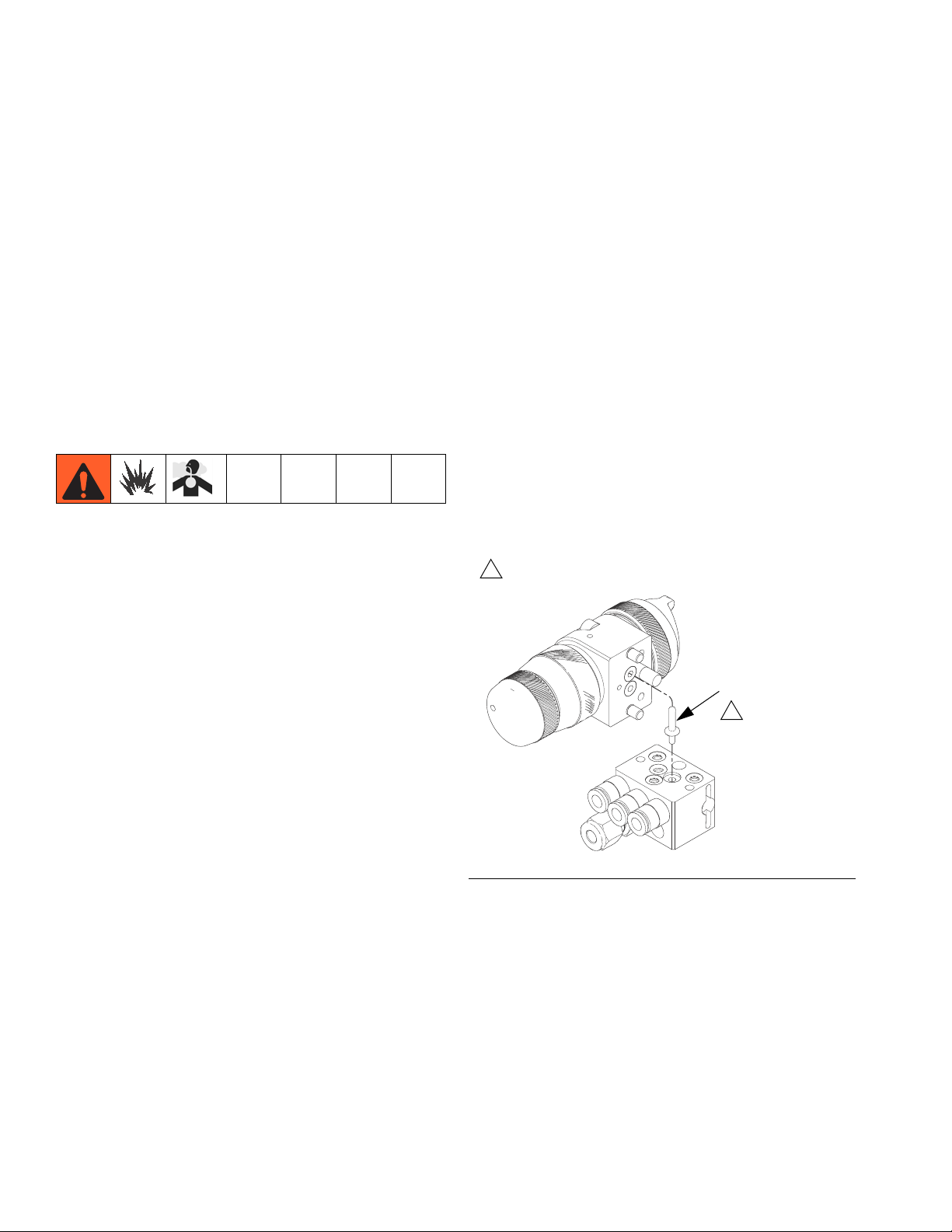
Configure Gun and Manifold
Guns with Manifold
See FIG. 1. The gun is shipped with a fluid plug
(25). To use the gun in a circulating system, do
not install the plug. In a non-circulating system,
install the plug as shown to minimize flush
time.
1. Connect the fluid supply line to one fluid
port fitting and the fluid return line to the
other. The manifold fluid ports are
reversible.
2. Install the gun on the manifold, using the
two screws. Torque the screws evenly to
50 in-lb (5.6 N•m).
1
Do not install when used in circulating systems.
• Check and follow all national, state, and
local codes regarding air exhaust velocity
requirements.
• Check and follow all local safety and fire
codes.
25
1
TI14429A
FIG. 1: Guns with Manifold
10 313869B
Page 11

Installation
Guns without Manifold
The gun is shipped ready for use in a circulating system, with a fitting installed in each fluid
port. Connect the fluid supply line to one fluid
inlet fitting (15) and the fluid return line to the
other.
To use the gun in a non-circulating system,
remove one fitting and replace with plug (33,
shipped loose). Use the 3/16 allen wrench
supplied to tighten the plug.
1
Install for use in a non-circulating system.
2
Use fitting (15) for use in a circulating system.
15
Pump/Fluid Supply
Ground the pump by connecting a ground wire
and clamp between the fluid supply and a true
earth ground as instructed in your separate
pump instruction manual.
Air Compressors and Hydraulic Power
Supplies
Ground the air compressors and hydraulic
power supplies according to the manufacturer
recommendations.
Spray Gun
Ground the spray gun by mounting the manifold to a properly grounded reciprocator, robot,
or stationary mount. Check the electrical resistance between the manifold and a true earth
ground. Resistance must not exceed
1 megohm.
1
33
TI14430A
FIG. 2: Guns without Manifold
2
Ground System
The following grounding instructions are minimum requirements for a system. Your system
may include other equipment or objects that
must be grounded. Check your local electrical
code for detailed grounding instructions for
your area and type of equipment. Your system
must be connected to a true earth ground.
Fluid Supply Container
Ground the fluid supply container according to
local code.
Object Being Sprayed
Ground the object that is being sprayed
according to local code.
Solvent Pails
Ground all solvent pails that are used when
flushing according to local code. Use only conductive metal pails placed on a grounded surface. Do not place the pail on a non-conductive
surface, such as paper or cardboard, which
interrupts the grounding continuity.
313869B 11
Page 12

Installation
Mount Gun
Reciprocating Arm Rod Mount
To mount the gun on a reciprocating arm rod
[0.75 in. (19 mm) diameter maximum], insert
the bar (A) through the hole in the manifold as
shown in FIG. 3.
NOTE: Use the 1/8 in. alignment slot (P) to
assist in orienting the gun.
Secure the gun to the bar by tightening the
mounting screw (B).
C
A
B
FIG. 3: Reciprocating Arm Mount
P
TI14433A
Stationary Support
To mount the gun on a stationary support, refer
to FIG. 4 and to the correct mounting hole layout for your gun, page 30 - 31.
1. Align the gun or manifold with the alignment pins. Locate alignment slot and holes
per the mounting hole layout.
Guns with manifold
C
Guns without manifold
FIG. 4: Stationary Support Mount
TI14434A
TI14435A
2. Secure the gun to the support with two M8
x 1.25 capscrews (C). The screws must be
long enough to engage the threaded holes
to a depth of 1/4 in. (6 mm).
12 313869B
Page 13

Setup
Setup
Connect Air Line
NOTE:
• If your regulated air source does not
have a filter, install an air filter (G) on
each air line to ensure a dry, clean air
supply to the gun. Dirt and moisture can
ruin the appearance of your finished
workpiece. See FIG. 5.
• You must install a separate air pressure
regulator (F) on the CYL, FAN, and
ATOM air lines to control air pressure to
the gun. See FIG. 6 and FIG. 7.
• Install a bleed type air shutoff valve (E)
on each gun air supply line, downstream of the gun air regulator, to shut
off air to the gun.
1. The gun cylinder, fan, and atomization air
must be supplied and regulated separately.
To regulate air remotely, use solenoids (see
FIG. 6 and FIG. 7).
NOTE: The three air inlet fittings accept 6 mm
OD tubing.
2. Connect each air hose (D) to a regulated
air supply line (H).
H
G
FIG. 5: Connect Air Line
FED
ti01990a
313869B 13
Page 14

Setup
Air regulator
ATOMIZING AIR
2-way solenoid
valve
CYLINDER AIR
3-way solenoid
valve
FAN AIR
FIG. 6: Remote Air Regulation using Solenoid (Guns with Manifold)
FAN AIR
CYLINDER AIR
2-way solenoid
TI14444A
valve
2-way solenoid
valve
3-way solenoid
valve
ATOMIZING AIR
TI14445A
2-way solenoid
valve
FIG. 7: Remote Air Regulation using Solenoid (Guns without Manifold)
14 313869B
Page 15

Setup
Connect Fluid Hose
NOTE:
• Before connecting the fluid line, blow it
out with air and flush it with solvent. Use
solvent that is compatible with the fluid
to be sprayed.
• Install a fluid regulator (L) on the fluid
line to control fluid pressure to the gun.
See FIG. 8.
• Install a fluid shutoff valve (M) to shut off
the fluid supply to the gun.
• Filter the fluid line of coarse particles
and sediment to avoid clogging the fluid
nozzle and causing finishing defects.
Inline fluid filter 24B707 is available.
L
In a non-circulating system, remove the
gun fluid outlet fitting (T) and plug the outlet
port with the pipe plug (33) supplied for
guns without manifold. Guns with manifold
use plug 24C211 (25, see page 10).
KEY
N Cylinder Air Inlet: accepts 6 mm OD tubing
P Atomization Air Inlet: 6 mm OD tubing
R Fan Air Inlet: 6 mm OD tubing
S Fluid Inlet: 6 mm OD tubing
T Fluid Outlet (circulating gun only): 6 mm OD tubing
With Manifold
N
RP
K
M
J
ti7016a
FIG. 8: Connect Fluid Hose.
1. Connect the fluid supply hose (J) to the gun
fluid inlet (S), 6 mm OD tube fitting. See
IG. 9.
F
2. Connect the other end of the fluid hose (J)
to a regulated fluid supply outlet (M).
3. In a circulating system, connect a
grounded fluid return hose to the gun fluid
outlet (T). See FIG. 9.
Without Manifold
T (or S)
P
N
FIG. 9: Air and Fluid Ports
S (or T)T (or S)
TI14436A
S (or T)
R
TI14437A
313869B 15
Page 16

Setup
Flush Spray Gun
Before running any paint through the spray
gun:
1. Flush the gun with a solvent that is compatible with the fluid to be sprayed, using the
lowest possible fluid pressure and a
grounded metal container. See Clean and
Flush Gun, page 20.
2. Perform Pressure Relief Procedure,
page 18.
Position Air Cap
Air caps are factory-set with the alignment pin
(A) set to a vertical spray pattern. To change
the air cap to a horizontal spray pattern, use a
1/16 in. hex wrench to unscrew the alignment
pin (A) and relocate it to the horizontal spray
pattern hole. When relocating the pin use low
strength thread locker. Torque to 1.5-2.5 in-lb
(0.2-0.3 N•m). Do not overtighten. Refer to
FIG. 10.
Adjust Spray Pattern
Do not exceed 100 psi (0.7 MPa, 7 bar)
maximum fluid and air pressure. Higher
pressures can cause parts to rupture and
result in serious injury.
Use the fluid pressure regulator to adjust the
spray gun fluid flow. All models are equipped
with a fluid control knob to make precise fluid
flow adjustments.
Follow these steps to establish the correct fluid
flow and air flow:
1. To achieve desired flow, adjust the fluid flow
using the fluid pressure regulator (L)
installed in the gun fluid line. Typical industrial flow rates will vary with regulator pressures from 5 to 30 psi (34 to 210 kPa,
0.3 to 2.1 bar). If the fluid pressure is too
low at the desired flow rate, install a smaller
nozzle. If the fluid pressure is too high,
install a larger nozzle.
For spray guns equipped with the fluid control knob, you can make flow rate changes
at the spray gun. Rotate the fluid control
knob clockwise to reduce the flow.
A
ti8171a
Vertical Pattern
A
Horizontal Pattern
ti8170a
ti8172a
FIG. 10: Position Air Cap
16 313869B
Page 17

L
ti7019a
FIG. 11: Fluid Pressure Regulator
NOTE: A larger fluid nozzle at a reduced fluid
pressure will maintain the same flow rate, but
the fluid stream (velocity) will slow down.
When air is applied, the lower velocity allows
the air to act on the fluid longer, which
improves atomization.
2. Using the air pressure regulator (F), set the
fan and atomizing air supply pressure per
Table 1. Use these suggested settings as a
starting point.
Table 1: Suggested Starting Settings
Spray
Type
Conven-
tional
HVLP 15 (0.1, 1.0) 15 (0.1, 1.0)
HiTEch 29 (0.2, 2.0) 29 (0.2, 2.0)
LVMP 43 (0.3, 3.0) 43 (0.3, 3.0)
Air Brush NA 29 (0.2, 2.0)
Fan Air
psi (MPa, bar)
43 (0.3, 3.0) 43 (0.3, 3.0)
Atomizing Air
psi (MPa, bar)
Setup
NOTE: HVLP Gun Limits
HVLP Guns: local laws may limit the maximum
pressure to 10 psi (70 kPa, 0.7 bar) at the air
cap for compliance. See the table on page 8
for maximum HVLP manifold inlet pressures.
To measure pressure at the air cap, use the
appropriate HVLP Pressure Verification Kit.
F
ti01997
FIG. 12: Air Pressure Regulator
3. Test the spray pattern atomization while
keeping the gun a consistent distance,
about 6 to 8 inches (150 to 200 mm), from
the test piece.
Check the atomization quality. Increase the
gun atomizing air supply pressure with the
air pressure regulator in 5 psi (34 kPa, 0.3
bar) increments until you obtain the desired
atomization.
NOTE: For the best transfer efficiency, use the
lowest setting needed to achieve desired finish
quality.
4. If the spray pattern is too wide or split,
reduce the fan air pressure.
NOTE: Reducing the fan air pressure to 0 psi
(or fully closing the fan adjustment valve) will
produce a round pattern.
To further control the spray pattern, use an
alternate air cap. For a list of available air caps,
see page 8.
313869B 17
Page 18

Operation
Operation
Pressure Relief Procedure
1. Turn off all bleed type air valves and all
other air and fluid supplies to the gun.
2. Trigger the gun into a grounded metal
waste container to relieve fluid pressure.
ti8174a
FIG. 13: Pressure Relief
To achieve best results when applying fluid:
• Keep gun perpendicular and 6 to 8 in.
(150 to 200 mm) from object being
sprayed.
• Use smooth, parallel strokes across sur-
face to be sprayed with 50% overlap.
Incorrect
TI14439A
Apply Fluid
The gun does not have an air shutoff. The air
should be activated before the fluid to ensure
full atomization of fluid and prevent buildup on
the air cap.
Adjust the system control device, if it is automatic, so the gun starts spraying just before
meeting the part and stops as soon as the part
has passed.
Correct
TI14438A
FIG. 14: Correct Spray Method
18 313869B
Page 19

Daily Gun Care
NOTICE
Methylene chloride with formic or propionic
acid is not recommended as a flushing or
cleaning solvent with this gun as it will
damage aluminum and nylon components.
NOTICE
Solvent left in gun air passages could result in a poor quality paint finish. Do not
use any cleaning method which may allow solvent into the gun air passages.
Do not wipe the gun with a cloth soaked
Do not point the gun up while cleaning it.
in solvent; wring out the excess.
Operation
ti8100a
ti4827a
Do not use metal tools to clean the air
cap holes as this may scratch them;
Do not immerse the gun in solvent.
ti8101a
313869B 19
scratches can distort the spray pattern.
ti8175a
Page 20

Operation
General System Maintenance
• Follow the Pressure Relief Procedure,
page 18.
• Clean the fluid and air line filters daily.
• Check for any fluid leakage from the gun
and fluid hoses. Tighten fittings or replace
equipment as needed.
• Flush the gun before changing colors and
whenever you are done operating the gun.
Clean and Flush Gun
1. Follow the Pressure Relief Procedure,
page 18.
2. Shut off the gun fan and atomizing air.
3. Supply a compatible solvent to the gun fluid
inlet.
4. Point the gun down into a grounded metal
container, and flush the gun with solvent
until all traces of paint are removed from
the gun passages.
9. Dip the end of a soft-bristle brush into a
compatible solvent. Do not continuously
soak the brush's bristles with solvent and
do not use a wire brush.
ti4845a
FIG. 15: Use solvent-dipped soft-bristle brush
10.With the gun pointed down, clean the front
of the gun, using the soft-bristle brush and
solvent.
11.Scrub the air cap retaining ring, air cap,
and fluid nozzle with the soft-bristle brush
(see FIG. 16). To clean out air cap holes,
use a soft implement, such as a toothpick,
to avoid damaging critical surfaces. Clean
the air cap and fluid nozzle daily, minimum.
Some applications require more frequent
cleaning.
5. Follow the Pressure Relief Procedure,
page 18.
6. Disconnect the solvent supply.
7. Remove the air cap retaining ring and air
cap.
NOTICE
Trigger the gun whenever you tighten or
remove the nozzle. This keeps the needle
IG. 16: Clean air cap, ring and fluid nozzle
F
ti8176a
seat away from the nozzle seating surface
and prevents the seat from being dam-
12.Install the air cap retaining ring and air cap.
aged.
13.Dampen a soft cloth with solvent and wring
8. Clean the air cap retaining ring, air cap,
and fluid nozzle with solvent.
20 313869B
out the excess. Point the gun down and
wipe off the outside of the gun.
Page 21

Operation
313869B 21
Page 22

Troubleshooting
Troubleshooting
Problem Cause Solution
Spray Pattern Normal pattern. No action necessary.
Right
Spray Pattern Dirty or damaged air cap or
fluid nozzle.
Wrong
Heavy top
or bottom
Spray Pattern Fan pressure too high for vis-
cosity of material being
sprayed.
Wrong
Split pattern
Rotate air cap (5) 180°.
If pattern follows air cap, problem is in air cap. Clean and
inspect. If pattern is not corrected, replace air cap.
If pattern does not follow the air
cap, the problem is with the
fluid nozzle (4). Clean and
inspect the nozzle. If the pattern is not corrected, replace
nozzle.
Reduce fan air pressure and
increase material viscosity.
Spray Pattern Dirty or distorted air horn
holes.
Clean and inspect air cap (5). If
pattern is not corrected,
replace air cap.
Wrong
22 313869B
Page 23

Troubleshooting
Problem Cause Solution
Gun spitting. Air getting into paint stream. Check if fluid source is empty
and fill.
Tighten fluid nozzle (4).
Check fluid nozzle o-ring (3) for
damage.
Check fluid nozzle (4) for damage.
Will not spray. Fluid control valve (11) turned
too far clockwise.
Adjust fluid control valve (11)
counterclockwise.
Fluid source empty. Refill.
Excessive air blowing back. Loose fluid nozzle (4). Tighten fluid nozzle (4).
Damaged fluid nozzle seal (3). Replace seal (3).
Gun fluid pressure is too high
with gun triggered (cannot
Using needle/nozzle kit with
too small orifice.
Use needle/nozzle kit with
larger orifice.
achieve desired flow rate).
Using a low fluid pressure set-
ting, the fluid flow is too high,
Using needle/nozzle kit with
too large orifice.
Use needle/nozzle kit with
smaller orifice.
making it necessary to restrict
needle travel to reduce fluid
flow.
Fluid system will not operate at
low enough pressure [below
10 psi (70 kPa, 0.7 bar)].
Fluid flow is fluttering while
spraying.
There is no fluid regulator, or
air regulator is not sensitive
enough at low pressure.
Add low pressure fluid regula-
tor, or add more sensitive low
pressure air regulator.
Fluid source empty. Refill.
313869B 23
Page 24

Service
Service
screws (16) and remove the gun from
the manifold.
NOTE: Numbers in parenthesis in the text refer
to the reference numbers in the figures and in
the parts list.
Disassembly
1. Follow the Pressure Relief Procedure,
page 18.
2. Remove gun for service:
a. With Manifold: Use the 4 mm allen
wrench supplied to unscrew the two
1
Torque to 155-165 in-lb (18-19 N•m).
2
Torque to 80 in-lb (9.0 N•m).
b. Without Manifold: Disconnect the air
and fluid hoses. Remove the gun from
the mounting arm.
3. Remove the air cap retaining ring (21) and
air cap (5).
4. Remove the fluid adjustment knob (11) and
spring (10).
5. Pull the piston (7) and fluid needle (6) out
of the back of the gun.
11
10
7
6
2
2
1
4
21
5
FIG. 17
24 313869B
ti14946a
Page 25

Service
6. Use a 1/16 hex wrench to loosen the fluid
needle set screw (7a). Remove the needle
(6) from the piston (7).
7. Check the fluid needle (6) for damage or
excessive wear. Replace the needle if necessary.
NOTICE
The needle and tip are permanently
bonded. To prevent damage to the needle,
do not try to separate.
8. Use the 10 mm hex nut driver to remove
the fluid packing nut (2).
9. Use the 10 mm wrench to remove the
nozzle (4).
Reassembly
1. Lightly grease the new nozzle (4), which
includes o-ring (3). Use the 10 mm wrench
to install the nozzle. Torque to 155-165 in-lb
(18-19 N•m).
2. Install the new air cap assembly (5,
includes air cap, o-ring, washer, and alignment pin) and the retaining ring (21).
7
1
7a
1
Torque to 4.5 to 5.5 in-lb (0.5 to 0.6 N•m).
FIG. 18
6
ti14944a
NOTICE
To avoid damage, the nozzle (4) must be
installed before the needle (6).
5. Grease the needle shaft and piston o-ring.
Push the needle/piston assembly into the
gun as far as possible. Insert spring (10).
6. Turn counterclockwise to fully open the fluid
adjustment knob (11). Install the knob
hand-tight.
NOTE: If you have an ultra-precision fluid
adjustment knob, loosen the set screw to
adjust the position of the hash markings for
convenient reading.
NOTE: Be sure to move the alignment pin if
you want a horizontal spray pattern. See Posi-
tion Air Cap, page 16.
3. Use the 10 mm hex nut driver to install new
fluid packing nut (2, includes o-ring).
Torque to 80 in-lb (9.0 N•m).
ti14947a
Set screw
4. Insert the new needle (6) in the piston (7).
FIG. 19
Apply medium-strength thread sealant to
the setscrew (7a). Use the 1/16 hex wrench
to torque the setscrew to 4.5 to 5.5 in-lb
(0.5 to 0.6 N•m).
313869B 25
Page 26

Parts
Parts
Guns with Manifold
5a
5c
5b
5d
18
7
7b
1
16
6
2
7a
Ultra-precision knob
3
4
Indexing
knob
Lock ring
20
13
20
13
15
14
10
11
and cap
21
Guns without Manifold
4
5d
5a
5b
5c
21
15
12
19
1
3
17
7a
2
7b
6
15
ti14447a
11
10
7
ti14945a
14
ti14448a
26 313869B
Page 27

Parts
Parts in Common Additional Parts for Models with Manifold
Ref. Part Description Qty.
1 ----- BODY 1
2 24C205 FLUID PACKING ASSEMBLY 1
3 111457 O-RING (included with Part 4) 1
4 See Table NOZZLE, fluid (includes Part 3) 1
5 See Table AIR CAP ASSEMBLY (includes
Parts 5a-5d)
5a ----- AIR CAP 1
5b✓ ----- O-RING 1
5c✓ ----- WASHER, UMHWPE 1
5d ----- PIN, alignment 1
6 See Table NEEDLE assembly 1
7 24C202 PISTON, needle stop (includes
Parts 7a and 7b)
7a ----- SCREW, set, 6-32 UNC x 1/16 in. 1
7b ----- O-RING 1
10 24C207 SPRING, compression 1
11
24D065
24C204
24C203
14 120538 FITTING, tube, air line,
15
24C213
24D046
21 289079 RETAINING RING, assembly
23 114141 TOOL, wrench, hex, 1/16, not
24 107157 TOOL, wrench, allen, 4 mm, not
26 101821 TOOL, wrench, allen, 3/16, not
31 24C210 TOOL, wrench, metric, not shown 1
32 24C209 TOOL, nut driver, hex, 10 mm,
33 100139 PLUG, pipe, not shown, shipped
KNOB, fluid adjustment
Ultra-Precision
Indexing
Lock ring and cap
1/8 npt x 6 mm
FITTING, tube, fluid line,
1/8 npt x 6 mm
Nylon
Stainless steel
(includes 5b and 5c)
shown
shown
shown (Models without manifold)
not shown
loose (Models without
manifold)
Ref. Part Description Qty.
12 24C215 MANIFOLD, gun (includes Parts
13, 14, 15, 19, and 20)
13 106456† O-RING, PTFE, white 2
16 24C206 SCREW, mounting 2
17 24C208 ROD, mounting (includes Part 18) 1
18 ----- SCREW, cap, hex head 1
19 24C212 SCREW, set socket, M8 2
20 112319† O-RING, FX75, black 3
25 24C211 PLUG, manifold, not shown,
shipped loose
----- Not sold separately.
1
✓ Included in Air Cap Seal Kit 289791. See Repair Kits,
page 28.
† Included in Manifold O-Ring Kit 24D827. See Repair
Kits, page 28.
1
3
2
1
1
1
1
1
1
1
1
313869B 27
Page 28

Repair Kits
Repair Kits
Gun Part Number
With
Spray Type
Conventional 24B857 24B877
Conventional 24B858 24B878
Conventional 24B859 24B879
Conventional 24B860 24B880
Conventional 24B861* ----HVLP 24B862 ----HVLP 24B863 24B881
HVLP 24B864 24B882
HVLP 24B865 24B883
HiTEch 24B866 24B884
HiTEch 24B867* 24B885*
HiTEch 24B868* 24B886*
LV MP 24B869 24B887
LV MP 24B870 24B888
LV MP 24B871 24B889
LV MP 24B872 24B890
LV MP 24B873 24B891
LV MP 24B874* ----Air Brush 24B875 24B892
Manifold
Without
Manifold
Item 5
Air Cap
(Includes seals
and alignment
pin)
Nozzle
Orifice
Size
in. (mm)
Needle/Nozzle
Kit
(Includes
Items 4 and 6)
Item 4
Nozzle
(includes
o-ring)
Item 6
Needle
Assembly
(includes
tip)
0.028 (0.7) 24D177 24D174 24C191
0.035 (0.9) 24C198 24C187 24C192
0.043 (1.1) 24C199 24C188 24C193
24C182
0.051 (1.3) 24C200 24C189 24C194
0.059 (1.5) 24D178 24D175 24C195
0.020 (0.5) 24D302 24D296 24C190
0.028 (0.7) 24D179 24D176 24C191
0.043 (1.1) 24D305 24D299 24C193
24C183
0.051 (1.3) 24D306 24D300 24C194
0.028 (0.7) 24D303 24D297 24C191
0.039 (1.0) 24C221 24C219 24C220
24D703
0.059 (1.5) 24C201 24D275 24C195 24D704
0.020 (0.5) 24D277 24D259 24C190
0.028 (0.7) 24D278 24D260 24C191
0.035 (0.9) 24D279 24D261 24C192
0.043 (1.1) 24D280 24D262 24C193
24C184
0.051 (1.3) 24D281 24D263 24C194
0.059 (1.5) 24D284 24D276 24C195
0.028 (0.7) 24C197 24C186 24C191 24D705
* Needle tip and nozzle exit constructed from tungsten carbide.
Accessories
Kit 24C216, Fittings (1/4 inch)
Part Description Qty.
120388 FITTING, tube, air line,
1/8 npt x 1/4 T
111157 FITTING, tube, fluid line,
1/8 npt x 1/4 T
3
2
Kit 24D143, Robot Adapter Kit
Fanuc Paint Mate 200
Compatible with and without manifold.
Kit 24D008, Inlet Air Needle Valve
Includes needle valve and 6mm tube fittings.
Kit 24D827, Manifold O-Rings
Part Description Qty.
106456 O-RING, PTFE, white 2
112319 O-RING, FX75, black 3
HVLP Pressure Verification Kit 24C214
For use in checking air cap atomizing and fan
pattern air pressure at various supply air pressures. Not to be used for actual spraying.
Install the kit air cap on the gun. Turn on the air
to the gun and read the air pressure on the
gauge.
NOTE: To be “HVLP compliant,” the atomizing
and fan pattern air pressure must not exceed
10 psi (70 kPa, 0.7 bar).
28 313869B
Page 29

Dimensions
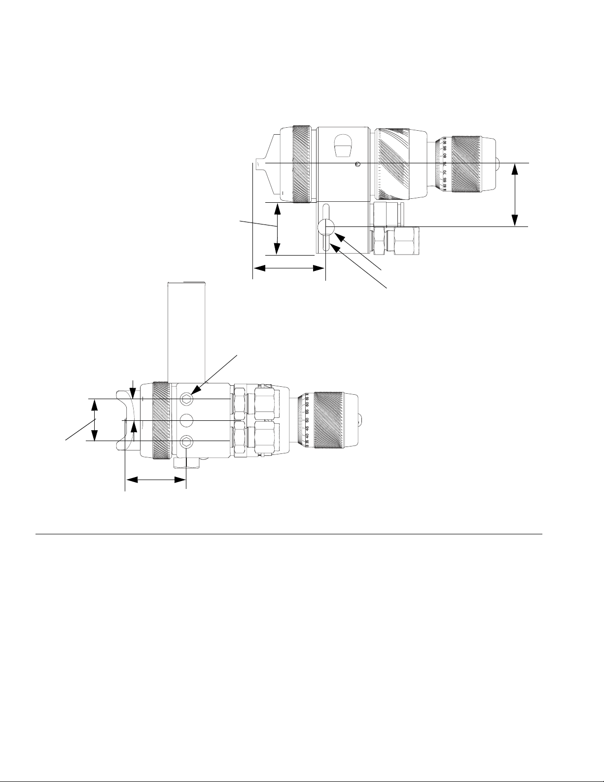
Guns with Manifold
Dimensions
1.3 in.
(33.0 mm)
FIG. 20
4.9 in. (124.5 mm) with Ultra-Precision knob
4.1 in. (104.1 mm) with indexing knob
3.5 in. (88.9 mm) with lock ring and cap
1.4 in.
(35.6 mm)
0.75 in. (19.1 mm)
mounting hole
2.6 in.
(66.1 mm)
TI14440A
1.6 in.
(40.7 mm)
3.8 in.
(96.5 mm)
TI14436A
Guns without Manifold
4.9 in. (124.5 mm) with Ultra-Precision knob
4.1 in. (104.1 mm) with indexing knob
3.5 in. (88.9 mm) with lock ring and cap
2.2 in.
(55.9 mm)
TI14442A
3.5 in.
(88.9 mm)
TI14437A
1.6 in.
(40.6 mm)
FIG. 21
313869B 29
Page 30
Mounting Hole Layouts
Mounting Hole Layouts
Guns with Manifold
0.95 in
(24.1 mm)
ti14700a
1.27 in
(32.3 mm)
0.86 in.
(21.8 mm)
FIG. 22
0.43 in.
(10.9 mm)
1.22 in.
(31.0 mm)
1.4 in
(35.6 mm)
3 x M8 x 1.25
0.34 in. (8.6 mm) thru
0.13 in. (3.3 mm) slot
ti14441a
30 313869B
Page 31

Guns without Manifold
0.95 in.
(24.1 mm)
Mounting Hole Layouts
1.76 in.
(44.7 mm)
M8 x 1.25 T
0.35 in. (8.9 mm) deep
0.13 slot
(3.3 mm)
FIG. 23
ti14701a
313869B 31
Page 32

Technical Data
Technical Data
Maximum working fluid pressure . . . . . . . . . . . . . . . . . . . . 100 psi (0.7 MPa, 7 bar)
Maximum working air pressure . . . . . . . . . . . . . . . . . . . . . 100 psi (0.7 MPa, 7 bar)
Maximum HVLP Inbound Air Pressure. . . . . . . . . . . . . . . . See chart on page 8.
Maximum Working Fluid Temperature . . . . . . . . . . . . . . . . 120° F (49° C)
Minimum Air Cylinder Actuation Pressure . . . . . . . . . . . . . 50 psi (0.34 MPa, 3.4 bar)
Weight
with manifold. . . . . . . . . . . . . . . . . . . . . . . . . . . . . . . . .
with no manifold . . . . . . . . . . . . . . . . . . . . . . . . . . . . . .
Wetted Parts
Models 24B857-24B860, 24B862-24B865,
24B869-24B873, 24B875 . . . . . . . . . . . . . . . . . . . . . . .
Model 24B866. . . . . . . . . . . . . . . . . . . . . . . . . . . . . . . . PTFE, Stainless Steel, Ultra High
Models 24B867 and 24B868. . . . . . . . . . . . . . . . . . . . . PTFE, Stainless Steel, Ultra High
1.3 lb (575 g)
0.6 lb (275 g)
Nylon, PTFE, Stainless Steel, Ultra
High Molecular Weight Polyethylene
Molecular Weight Polyethylene
Molecular Weight Polyethylene,
tungsten carbide
Models 24B861 and 24B874. . . . . . . . . . . . . . . . . . . . . Nylon, PTFE, Stainless Steel, Ultra
High Molecular Weight Polyethylene,
Tungsten Carbide
Models 24B877-24B883, 24B887-24B892 . . . . . . . . . . Anodized Aluminum, Nylon, Stain-
less Steel, Ultra High Molecular
Weight Polyethylene
Models 24B885 and 24B886. . . . . . . . . . . . . . . . . . . . . Anodized Aluminum, Stainless Steel,
Tungsten Carbide, Ultra High Molecular Weight Polyethylene
Model 24B884. . . . . . . . . . . . . . . . . . . . . . . . . . . . . . . . Anodized Aluminum, Stainless Steel,
Ultra High Molecular Weight
Polyethylene
Triggering Speed
These values apply to a new gun with a 12 ft. (3.6 m), 1/4 in. (6.3 mm) OD cylinder air line and a
0.043 in. nozzle. These values will vary slightly with use and with variations in equipment.
Cylinder Air
Pressure
psi (kPa, bar)
Fluid Pressure
psi (kPa, bar)
Air Pressure
psi (kPa, bar)
msec to fully
open
msec to fully
close
50 (0.35, 3.5) 50 (0.35, 3.5) 100 (0.7, 7.0) 48 84
32 313869B
Page 33

Sound Data
Conventional
Measured at 43 psi (0.30 MPa, 3.0 bar) atomizing air and
fan air pressure
Sound Power. . . . . . . . . . . . . . . . . . . . . . . . . . . . . . . .
Sound Pressure . . . . . . . . . . . . . . . . . . . . . . . . . . . . .
HVLP
Measured at 15 psi (0.10 MPa, 1.0 bar) atomizing air
and fan air pressure
Sound Power. . . . . . . . . . . . . . . . . . . . . . . . . . . . . . . .
Sound Pressure . . . . . . . . . . . . . . . . . . . . . . . . . . . . .
HiTEch
Measured at 29 psi (0.20 MPa, 2.0 bar) atomizing air
and fan air pressure
Sound Power. . . . . . . . . . . . . . . . . . . . . . . . . . . . . . . .
Sound Pressure . . . . . . . . . . . . . . . . . . . . . . . . . . . . .
LVM P
Measured at 43 psi (0.30 MPa, 3.0 bar) atomizing air and
fan air pressure
Sound Power. . . . . . . . . . . . . . . . . . . . . . . . . . . . . . . .
Sound Pressure . . . . . . . . . . . . . . . . . . . . . . . . . . . . .
Air Brush
Measured at 29 psi (0.20 MPa, 2.0 bar) atomizing air and
fan air pressure
Sound Power. . . . . . . . . . . . . . . . . . . . . . . . . . . . . . . .
Sound Pressure . . . . . . . . . . . . . . . . . . . . . . . . . . . . .
Technical Data
87.76 dBa
81.11 dBa
78.46 dBa
71.82 dBa
85.61 dBa
79.23 dBa
86.59 dBa
79.92 dBa
73.03 dBa
66.28 dBa
Sound power measured per ISO 9614-2.
313869B 33
Page 34

Air Flow
Air Flow
See the chart to determine air consumption. Add the air consumption values shown for the atomizing air and fan air to get the total air consumption. For example, air cap 24C182 with 35 psi inlet
pressure uses 3.9 scfm atomizing air and 5.4 scfm fan air for a total of 9.3 scfm air consumption.
Air Cap
24C182
(Conv.)
24C183
(HVLP)
24D703
24D704
(HiTEch)
Atomizing
Gun/Manifold
Inlet Pressure
psi (MPa, bar)
10 (0.07, 0.7) 1.5 (0.04) 2.0 (0.06)
15 (0.10, 1.0) 2.0 (0.06) 2.7 (0.08)
20 (0.14, 1.4) 2.5 (0.07) 3.3 (0.09)
25 (0.17, 1.7) 3.0 (0.08) 4.0 (0.11)
30 (0.21, 2.1) 3.5 (0.10) 4.7 (0.13)
35 (0.24, 2.4) 3.9 (0.11) 5.4 (0.15)
40 (0.28, 2.8) 4.4 (0.12) 6.0 (0.17)
45 (0.31, 3.1) 4.9 (0.14) 6.7 (0.19)
50 (0.34, 3.4) 5.4 (0.15) 7.4 (0.21)
10 (0.07, 0.7) 2.2 (0.06) 1.9 (0.05)
15 (0.10, 1.0) 3.0 (0.08) 2.5 (0.07)
20 (0.14, 1.4) 3.8 (0.11) 3.1 (0.09)
25 (0.17, 1.7) 4.6 (0.13) 3.8 (0.11)
30 (0.21, 2.1) 5.4 (0.15) 4.4 (0.12)
35 (0.24, 2.4) 6.2 (0.18) 5.0 (0.14)
40 (0.28, 2.8) 7.0 (0.20) 5.6 (0.16)
45 (0.31, 3.1) 7.8 (0.22) 6.3 (0.18)
50 (0.34, 3.4) 8.6 (0.24) 6.9 (0.19)
10 (0.07, 0.7) 2.2 (0.06) 1.9 (0.05)
15 (0.10, 1.0) 3.0 (0.08) 2.5 (0.07)
20 (0.14, 1.4) 3.8 (0.11) 3.1 (0.09)
25 (0.17, 1.7) 4.6 (0.13) 3.8 (0.11)
30 (0.21, 2.1) 5.4 (0.15) 4.4 (0.12)
35 (0.24, 2.4) 6.2 (0.18) 5.0 (0.14)
40 (0.28, 2.8) 7.0 (0.20) 5.6 (0.16)
45 (0.31, 3.1) 7.8 (0.22) 6.3 (0.18)
50 (0.34, 3.4) 8.6 (0.24) 6.9 (0.20)
Air Flow
SCFM
(m3/min)
Fan Pattern
Air Flow
SCFM
(m3/min)
Air Cap
24C184
(LVMP)
24D705
(Air
Brush)
Atomizing
Gun/Manifold
Inlet Pressure
psi (MPa, bar)
10 (0.07, 0.7) 1.3 (0.04) 1.9 (0.05)
15 (0.10, 1.0) 1.7 (0.05) 2.5 (0.07)
20 (0.14, 1.4) 2.2 (0.06) 3.2 (0.09)
25 (0.17, 1.7) 2.6 (0.07) 3.9 (0.11)
30 (0.21, 2.1) 3.1 (0.09) 4.6 (0.13)
35 (0.24, 2.4) 3.5 (0.10) 5.2 (0.15)
40 (0.28, 2.8) 4.0 (0.11) 5.9 (0.17)
45 (0.31, 3.1) 4.5 (0.13) 6.6 (0.19)
50 (0.34, 3.4) 4.9 (0.14) 7.2 (0.20)
10 (0.07, 0.7) 1.5 (0.04) N/A
15 (0.10, 1.0) 2.0 (0.06) N/A
20 (0.14, 1.4) 2.5 (0.07) N/A
25 (0.17, 1.7) 3.0 (0.08) N/A
30 (0.21, 2.1) 3.5 (0.10) N/A
35 (0.24, 2.4) 3.9 (0.11) N/A
40 (0.28, 2.8) 4.4 (0.12) N/A
45 (0.31, 3.1) 4.9 (0.14) N/A
50 (0.34, 3.4) 5.4 (0.15) N/A
Air Flow
SCFM
3
(m
/min)
Fan Pattern
Air Flow
SCFM
(m3/min)
34 313869B
Page 35

Air Flow
Spray Pattern Test Report
Every AirPro EFX gun must pass a spray pattern test. The test report is printed and shipped in the box with the gun.
A sample is reproduced here, with explanatory notes.
AirPro EFX
Width: the distance from
one end of the pattern to
the other along the spray
pattern major axis.
Height: The distance from
one end of the pattern to
the other along the spray
pattern minor axis.
Consistency: The calculat-
ed variation in concentra-
tion along the spray pattern
major axis.
Position: The distance be-
tween the intended spray
gun center target location
and the actual spray
pattern center location.
Curvature: The vertical
distance between the
spray pattern location and
a line formed by the
intersections of the spray
pattern end points on the
major axis.
Tilt: The angle between a
horizontal line and a line
formed by the spray
pattern major axis.
Spray Pattern Test Report
Test Number: 1234
Operator: JI
Date: 6/17/2009
Part Number: 24B857
Date Code: F09A
Spray Pattern Test Parameters
Width: Passed
Height: Passed
Consistency: Passed
Position: Passed
Curvature: Passed
Tilt: Passed
Actual spray pattern image
Notes:
x Detailed descriptions of the spray pattern test parameters can be found in instruction manual 313869.
x Spray pattern shape is dependent on the material type, material flow rate and air pressure.
Name of the technician who certified your gun.
Date on which the spray test was performed.
Certifies that the gun is within acceptable
Use this number for reference in
limits on all parameters.
Colors (if visible) represent paint
density, with red meaning most paint
particles and blue meaning fewest.
communications with Graco.
Part number of your gun.
Date code for Graco use only.
313869B 35
Page 36

Graco Standard Warranty
Graco warrants all equipment referenced in this document which is manufactured by Graco and bearing its name to be free from defects in
material and workmanship on the date of sale to the original purchaser for use. With the exception of any special, extended, or limited warranty
published by Graco, Graco will, for a period of twelve months from the date of sale, repair or replace any part of the equipment determined by
Graco to be defective. This warranty applies only when the equipment is installed, operated and maintained in accordance with Graco’s written
recommendations.
This warranty does not cover, and Graco shall not be liable for general wear and tear, or any malfunction, damage or wear caused by faulty
installation, misapplication, abrasion, corrosion, inadequate or improper maintenance, negligence, accident, tampering, or substitution of
non-Graco component parts. Nor shall Graco be liable for malfunction, damage or wear caused by the incompatibility of Graco equipment with
structures, accessories, equipment or materials not supplied by Graco, or the improper design, manufacture, installation, operation or
maintenance of structures, accessories, equipment or materials not supplied by Graco.
This warranty is conditioned upon the prepaid return of the equipment claimed to be defective to an authorized Graco distributor for verification of
the claimed defect. If the claimed defect is verified, Graco will repair or replace free of charge any defective parts. The equipment will be returned
to the original purchaser transportation prepaid. If inspection of the equipment does not disclose any defect in material or workmanship, repairs will
be made at a reasonable charge, which charges may include the costs of parts, labor, and transportation.
THIS WARRANTY IS EXCLUSIVE, AND IS IN LIEU OF ANY OTHER WARRANTIES, EXPRESS OR IMPLIED, INCLUDING BUT NOT LIMITED
TO WARRANTY OF MERCHANTABILITY OR WARRANTY OF FITNESS FOR A PARTICULAR PURPOSE.
Graco’s sole obligation and buyer’s sole remedy for any breach of warranty shall be as set forth above. The buyer agrees that no other remedy
(including, but not limited to, incidental or consequential damages for lost profits, lost sales, injury to person or property, or any other incidental or
consequential loss) shall be available. Any action for breach of warranty must be brought within two (2) years of the date of sale.
GRACO MAKES NO WARRANTY, AND DISCLAIMS ALL IMPLIED WARRANTIES OF MERCHANTABILITY AND FITNESS FOR A
PARTICULAR PURPOSE, IN CONNECTION WITH ACCESSORIES, EQUIPMENT, MATERIALS OR COMPONENTS SOLD BUT NOT
MANUFACTURED BY GRACO. These items sold, but not manufactured by Graco (such as electric motors, switches, hose, etc.), are subject to
the warranty, if any, of their manufacturer. Graco will provide purchaser with reasonable assistance in making any claim for breach of these
warranties.
In no event will Graco be liable for indirect, incidental, special or consequential damages resulting from Graco supplying equipment hereunder, or
the furnishing, performance, or use of any products or other goods sold hereto, whether due to a breach of contract, breach of warranty, the
negligence of Graco, or otherwise.
FOR GRACO CANADA CUSTOMERS
The Parties acknowledge that they have required that the present document, as well as all documents, notices and legal proceedings entered into,
given or instituted pursuant hereto or relating directly or indirectly hereto, be drawn up in English. Les parties reconnaissent avoir convenu que la
rédaction du présente document sera en Anglais, ainsi que tous documents, avis et procédures judiciaires exécutés, donnés ou intentés, à la suite
de ou en rapport, directement ou indirectement, avec les procédures concernées.
Graco Information
For the latest information about Graco products, visit www.graco.com.
TO PLACE AN ORDER, contact your Graco distributor or call to identify the nearest distributor.
Phone: 612-623-6921 or Toll Free: 1-800-328-0211 Fax: 612-378-3505
All written and visual data contained in this document reflects the latest product information available at the time of publication.
Graco reserves the right to make changes at any time without notice.
Original instructions. This manual contains English. MM 313869
Graco Headquarters: Minneapolis
International Offices: Belgium, China, Japan, Korea
GRACO INC. P.O. BOX 1441 MINNEAPOLIS, MN 55440-1441
Copyright 2009, Graco Inc. is registered to ISO 9001
www.graco.com
Revised 04/2010
 Loading...