

Page 1
Instructions-Parts List
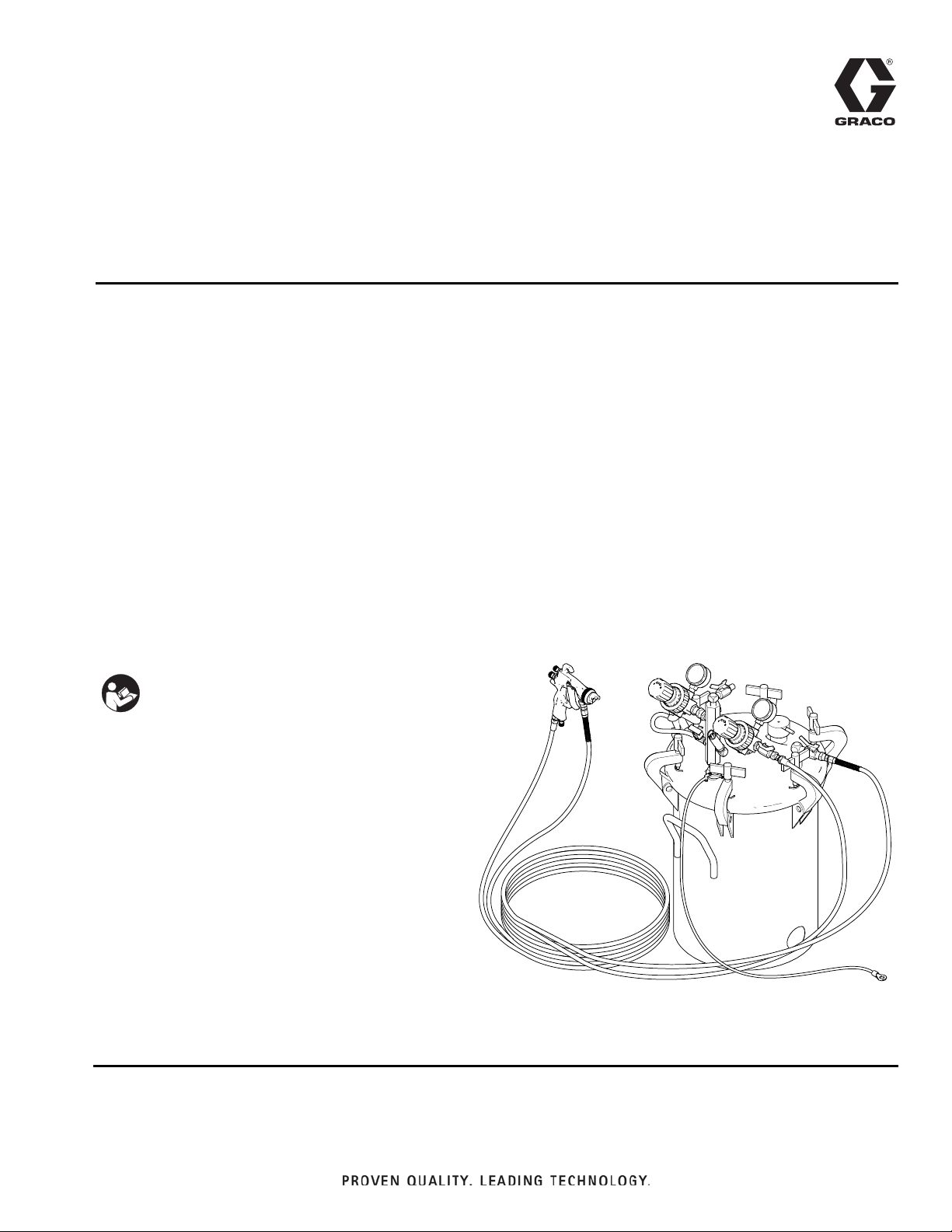
ti0751
Model 237409 shown
5 GAL. (20 LITER) STAINLESS STEEL (ASME) PRESSURE POT
308455N
AirPro™ Air Spray Package
Fine-finish spray package for waterborne and solvent-based fluids. For professional use
only.
100 psi (0.7 MPa, 7.0 bar) Maximum Fluid Working Pressure
100 psi (0.7 MPa, 7.0 bar) Maximum Air Input Pressure
Model 237409, Series B
Complete package includes pressure pot,
AirPro air spray gun with 0.055 (1.4 mm) fluid nozzle 25 ft. (7.6 m)
air and fluid hoses, and air and fluid controls.
EN
Model 237413, Series A
Complete package includes pressure pot, AirPro
HVLP spray gun with 0.055 (1.4 mm) fluid nozzle 25
ft. (7.6 m) air and fluid hoses, an d air and fluid controls.
Important Safety Instructions
Read all warnings and instructions in this
manual, and on the unit, including the power
cord. Save these instructions.
This manual provides basic safety, installation
and operation information for the package.
For your safety, also read the component
manuals supplied with this package before
operating it.
Page 2

Table of Contents
Table of Contents
Table of Contents . . . . . . . . . . . . . . . . . . . . . . . . . . 2
Warnings . . . . . . . . . . . . . . . . . . . . . . . . . . . . . . . . . 3
Setup . . . . . . . . . . . . . . . . . . . . . . . . . . . . . . . . . . . . . 5
Prepare the operator . . . . . . . . . . . . . . . . . . . . . . 5
Prepare the site . . . . . . . . . . . . . . . . . . . . . . . . . . 5
Component Identification . . . . . . . . . . . . . . . . . . 6
Unpack the system . . . . . . . . . . . . . . . . . . . . . . . 7
Connect the hose set and gun to the system . . . 7
Ground the system . . . . . . . . . . . . . . . . . . . . . . . 7
System Component Information . . . . . . . . . . . . . . 8
How to use the AirPro gun . . . . . . . . . . . . . . . . . 8
How to adjust the air regulators . . . . . . . . . . . . . 9
Safety relief valve . . . . . . . . . . . . . . . . . . . . . . . . 9
Operation . . . . . . . . . . . . . . . . . . . . . . . . . . . . . . . . 10
Pressure Relief Procedure . . . . . . . . . . . . . . . . 10
Flush the pressure pot before the first use . . . . 11
Prime the system . . . . . . . . . . . . . . . . . . . . . . . 11
Set the fluid and air pressure . . . . . . . . . . . . . . 11
System Shutdown . . . . . . . . . . . . . . . . . . . . . . . 12
Flushing . . . . . . . . . . . . . . . . . . . . . . . . . . . . . . 12
Parts . . . . . . . . . . . . . . . . . . . . . . . . . . . . . . . . . . . . 14
Model 237409, Series B . . . . . . . . . . . . . . . . . . 14
Model 237413, Series A . . . . . . . . . . . . . . . . . . 16
Technical Specifications . . . . . . . . . . . . . . . . . . . . 18
California Proposition 65 . . . . . . . . . . . . . . . . . . . 18
Notes . . . . . . . . . . . . . . . . . . . . . . . . . . . . . . . . . . . . 19
Graco Standard Warranty . . . . . . . . . . . . . . . . . . . 20
2
Page 3
Warnings
WARNINGWARNINGWARNING
WARNING
Warnings
The following warnings are for the setup, use, grounding, maintenance, and repair of this equipment. The exclamation point symbol alerts you to a general warning and the hazard symbols refer to procedure-specific risks. When
these symbols appear in the body of t his manual or on warn ing labels, ref er back to these Warnings. Product-specific
hazard symbols and warnings not covered in this section may appear throughout the body of this manual where
applicable.
PRESSURIZED EQUIPMENT HAZARD
Fluid from the equipment, leaks, or ruptured compon ents can splash in the eyes o r on skin and cause se rious injury.
• Follow the Pressure Relief Procedure when you stop spraying/dispensing and before cleaning,
checking, or servicing equipment.
• Tighten all fluid connections before operating the equipment.
• Check hoses, tubes, and couplings daily. Replace worn or dama ged parts immediately.
• Handle and route hoses and tubes carefully. Keep the hoses and tubes away fr om moving parts and
hot surfaces. Do not use the hoses to pull equipment. Do not expose Graco hoses to temperatures
above 180°F (82°C) or below -40°F (-40°C).
FIRE AND EXPLOSION HAZARD
Flammable fumes, such as solvent and paint fumes, in work area can ignite or explode. To help prevent
fire and explosion:
• Use equipment only in well ventilated area.
• Eliminate all ignition sources; such as pilot lights, cigarettes, portable electric lamps, and plastic drop
cloths (potential static arc).
• Keep work area free of debris, including solvent, rags and gasoline .
• Do not plug or unplug power cords, or turn powe r or light switches on or off wh en flammable fumes are
present.
• Ground all equipment in the work area. See Grounding instructions.
• Use only grounded hoses.
• Hold gun firmly to side of grounded pail whe n triggering into pa il. Do not use pail liners u nless they are
antistatic or conductive.
• Stop operation immediately if static sparking occurs or you feel a shock. Do not use equipmen t until
you identify and correct the problem.
• Keep a working fire extinguisher in the work area.
3
Page 4
Warnings
WARNINGWARNINGWARNING
WARNING
EQUIPMENT MISUSE HAZARD
Misuse can cause death or serious injury.
• Do not operate the unit when fatigued or under the influence of drugs or alcohol.
• Do not exceed the maximum working pressure or temperature rating of the lowest rated system component. See Technical Data in all equipment manuals.
• Use fluids and solvents that are compatible with equipment we tted parts. See Technical Data in all
equipment manuals. Read fluid and solvent manufacturer’ s warnings. For complete infor mation about
your material, request MSDS from distributor or retailer.
• Do not leave the work area while equipment is energized or under pre ssure.
• Turn off all equipment and follow the Pressure Relief Procedure when equipment is not in use.
• Check equipment daily. Repair or replace worn or d ama ged pa rt s immediat ely with ge nuin e manu fa cturer’s replacement parts only.
• Do not alter or modify equipment. Alterations or modifications may void agency approvals and create
safety hazards.
• Make sure all equipment is rated and approved for the environment in which you are using it.
• Use equipment only for its intended purpose. Call your distributor for information.
• Route hoses and cables away from traffic areas, sharp edges, moving pa rts, and hot surfaces.
• Do not kink or over bend hoses or use hoses to pull equipment.
• Do not expose Graco hoses to temperatures above 180°F (82°C) or below -40°F (-40°C).
• Keep children and animals away from work ar ea .
• Comply with all applicable safety regulations.
TOXIC FLUID OR FUMES HAZARD
Toxic fluids or fumes can cause serious injury or death if splashe d i n the eyes o r on skin, inha led, or swallowed.
• Read MSDSs to know the specific hazards of t he fluids you are using.
• Store hazardous fluid in approved containers, and dispo se of it according to applicable guidelines.
PERSONAL PROTECTIVE EQUIPMENT
Wear appropriate protective equip ment when in t he work area to help prevent serious injur y, including eye
injury, hearing loss, inhalation of toxic fumes, and bu rns. Th is protect ive eq uipment in cludes but is not limited to:
• Protective eyewear, and hearing protection.
• Respirators, protective clothing, and gloves as recommended by the fluid and solvent manufacturer
4
Page 5
Setup
NOTICE
This equipment is compatible with most water-based
materials. See the wetted parts in the Technical
Specifications section and your fluid and solvent
manufacturer’s compatibility information.
Prepare the operator
All persons who operate the system should be trained in
the safe, efficient operation of all system components as
well as the proper handling of the chemical coating. At a
minimum, all operators should thoroughly read the
safety, installation and operation sections of t his manual
and the component manuals.
Setup
Prepare the site
To prevent hazardous concentrations of toxic and/or
flammable vapors, spray only in a properly ventilated
spray booth. Never operate the spray gun unless
ventilation fans are operating. Check and follow all
of the national, state and local codes re garding air
exhaust velocity requirements.
1. Use a minimum 5 HP (3.7 kW) air compressor for
efficient operation.
2. Clear obstacles and debris that could cause an
unsafe operating environment.
3. Bring an air line from your compressed air supply to
the pressure pot location. Be sure the air is dry and
filtered. Install a bleed-type master air valve
upstream from the pressure pot. When it is closed
and the pressure pot air regulator (33) is opened,
the bleed-type master air valve relieves all air pres sure to the equipment components.
4. Ventilate the spray booth.
5
Page 6
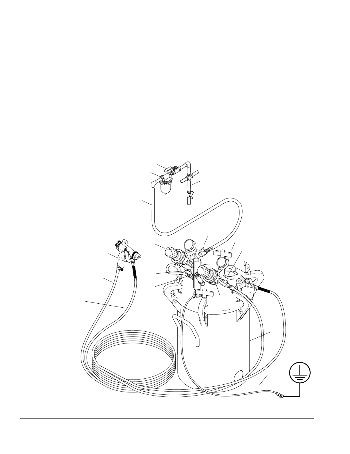
Setup
ti0750
KEY
Components you must supply:
A Bleed-type master air valve
Required for pump; order part
no. 110223, 1/4” npt(f)
B Air filter.
Order part no. 110146, 1/4 npt(f)
C Air supply line
D Air line moisture trap
Components supplied with package:
4 Pressure relief valve
7 Air relief valve
13 Ground wire
17a Gun air shutoff valve
17b Pressure pot air shutoff valve
18 Gun fluid shutoff valve
27 Pressure Pot
33 Pressure pot air regulator
36 Gun air regulator
40 Gun flui d hose
42 AirPro air/HVLP spray gun
43 Gun air hose
A
B
C
17b
18
17A
36
27
13
43
42
40
33
7
4
D
Model 237413 shown
Component Identification
FIG. 1
6
Page 7

Setup
Unpack the system
1. In addition to the assembled unit, t hese components
are packed loosely or separately: hose set, gun,
instruction manuals. These are the manuals you
should receive:
308369 Pressure pot
308167 Air regulator
312414 HVLP spray gun (Model 237413)
312414 Air spray gun (Model 237409)
Connect the hose set and gun to the system
See FIG. 1 on page 6
1. Connect the air hose (43) between the gun air shutoff valve (17a) and the air inlet of the spray gun.
These are 1/4- 18 npsm swivel fittings.
2. Connect the fluid hose (40) between the fl uid shutoff
valve (18) and the fluid inlet of the spray gun. These
are 3/8- 18 npsm swivel fittings.
Ground the system
The equipment must be grounded to reduce the risk
of static sparking. Static sparking can cause fumes to
ignite or explode. Grounding provides an escape wire
for the electric current. Check your local electrical
code for detailed grounding instructions for your area
and type of equipment.
Ground all of this equipment:
Pressure pot: One end of the ground wire (13) is
already connected to the pressure pot. Con nec t th e
other end of the ground wire to a true eart h ground.
Air compressor: Ground according to manufacturer’s
recommendations.
Object being sprayed: Ground according to local code.
Fluid supply container: Ground according to local
code.
3. Verify that all fittings throughout the system ar e
tightened securely.
All solvent pails used when flushing: Ground according to local code. Use only metal pails, which are conductive. Do not place the pail on a non-conductive
surface, such as paper or cardboard, which interrupts
the grounding continuity.
7
Page 8

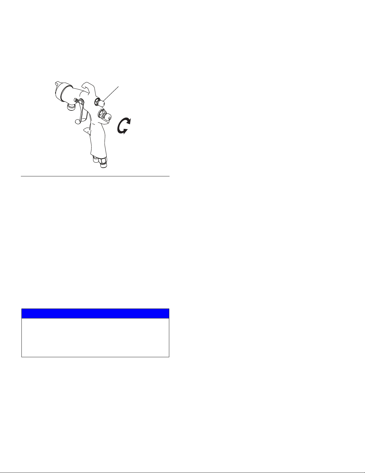
System Component Information
ti2120a
H
G
E
F
CW
CCW
Air cap horns shown
horizontal which produces
a vertical spray pattern
Air cap horns shown vertical
which produces a horizontal spray
pattern
ti2122a
System Component Information
How to use the AirPro gun
See FIG. 2
1. Make all fluid and air adjustments at the pressure
pot for maximum efficiency. See How to adjust the
air regulators, page 9.
NOTE: Monitor the adjustments made to the gun so if
the results are not satisfactory it can easily be retur ned
to its previous adjustment. Refer to your gun manual for
more information.
2. Adjusting Air Spray Gun: Use the fan pattern
adjusting valve (E). Normal adjustment is with the
valve turned out fully clockwise and then turned in
two full turns.
• Turn counterclockwise to widen spray pattern.
• Turn clockwise to narrow spray patter n.
Adjusting HVLP Spray Gun: Use the fan pattern
adjusting valve (E).
• For a round spray pattern, turn the pattern
adjusting valve fully in (clockwise).
• For an oval (flat) spray pattern, turn the pattern
adjusting valve fully out (counterclockwise).
6. Clean and lubricate the gun as instructed in your
separate gun manual.
FIG. 2
3. The fluid adjusting valve (F) is used in systems that
do not have a fluid regulator. As this package
includes a pressure pot regulator (33), use it to
adjust fluid flow. Turn the valve (F) out until full trigger travel is obtained.
4. The gun has a built-in lead and lag operation. When
triggered, the gun emits air before the fluid is discharged. When the trigger is released, the fluid
stops before the air flow stops. This helps assure
the spray is atomized and prevents fluid buildup on
the air cap.
5. Loosen the air cap retaining ring (G) and rotate the
horns (H) of the air cap to obtain the desired spray
position. Tighten the retaining ring snugly, but do not
over tighten it. See F
8
IG. 2 and FIG. 3.
FIG. 3
Page 9

How to adjust the air regulators
4066
Model 237413 shown
33
4
36
See FIG. 4
1. Always open air regulators slowly to prevent surging
during startup.
2. As you look at the system, the regulator (36) on the
right controls air to the gun and the regulat or (33) on
the left controls air to the pressure pot.
3. Model 237409 has two T-handle air regulators (33
and 36). Model 237413 (shown in F
T-handle air regulator (36) and one air regulator with
an adjustment knob (33).
T-Handle Air Regulator
Turn the T-handle (36 and 33- Model 237409 only) in
(clockwise) to open the air regulator. Turn the T-handle
fully out (counterclockwise) to close it. Be sure the jam
nut under the T-handle does not interfere with your
adjustments. Tighten the jam nut to lock in the setting, if
desired.
IG. 4) has one
System Component Information
Air Regulator with Adjustment Knob
Model 237413 only
Pull out the adjustment knob (33), and turn the knob in
(clockwise) to open the air regulator; turn the knob fully
out (counterclockwise) to close it. Push the adjusting
knob in to lock the setting if desired.
FIG. 4
Safety relief valve
See FIG. 4.
The safety relief valve (4) automatically relieves the
pressure pot pressure when the air pressure exceeds
approximately 100 psi (0.7 MPa, 7.0 bar). It resets automatically when the pressure is relieved. Refer to the test
procedure in manual 308369.
9
Page 10

Operation
ti0750
A Bleed-type master air valve
4 Pressure relief valve
7 Air relief valve
17a Gun air shutoff valve
17b Pressure pot air shutoff valve
18 Gun fluid shutoff valve
27 C-clamps
33 Pressure pot air regulator
36 Gun air regulator
40 Gun fluid hose
43 Gun air hose
A
43
40
33
7
4
36
17b
18
17a
27
Model 237413 shown
Operation
Pressure Relief Procedure
This equipment stays pressurized until pressure is
manually relieved. To help prevent seriou s injury from
pressurized fluid, such as skin injection, splashing
fluid and moving parts, follow the Pressure Relief
Procedure when you stop spraying and before
cleaning, checking, or servicing the equipment.
1. Close the gun air shutoff valve (17a). See FIG. 5.
2. Open the air relief valve (7) by turning it counter
clockwise. Leave it open until you reinstall the pressure pot cover (torque c-clamp to 8-10 ft-lbs) or fill
port.
3. Wait until there is no air escaping through the drain
cock fitting before removing the pressure pot cover
or opening the fill port.
FIG. 5
10
Page 11

Operation
Fluid Viscosity
Measured with a #2 Zahn cup
Light (18-25 seconds)
Medium (25-40 seconds)
Heavy (40-60 seconds)
Fluid Droop
8-10” (200-250 mm)
6-8” (150-200 mm)
4-6” (100-150 mm)
1
Fluid Droop: straight
stream before fluid
drops off
1
1
Air Spray Gun
ti12121a
Fluid Viscosity
Measured with a #2 Zahn cup
Light (18-25 seconds)
Medium (25-40 seconds)
Heavy (40-60 seconds)
Fluid Droop
4-6” (100-150 mm)
2-4” (50-100 mm)
1-2” (25-50 mm)
1
Fluid Droop: straight
stream before fluid
drops off
1
1
HVLP Spray Gun
ti12121a
Flush the pressure pot before the first use
Flush with a solvent compatible to your fluid. Consult the
fluid manufacturer’s literature for r ecommendations. See
Flushing on page 12.
Prime the system
1. Remove the pressure pot cover.
2. Place a 5 gal. (20 liter) metal pail of fluid in t he pressure pot, or install the pressure pot liner (supplied)
and fill it with up to 5 gal. (20 liter) of fluid.
NOTE: Order part no.15D059 fo r a package of 20 liners.
3. Tighten the c-clamp handles (27) secure ly.
4. Close the pressure pot and gun air regulators (33,
36).
5. Be sure the air relief valve (7) is closed (clockwise).
6. Be sure the pressure pot air shutoff valve (17b) is
closed (valve handle at a right angle to the valve
body), and then connect the air line (C) to the valve.
7. Open the master air valve (A).
To determine the fluid pressure setting, hold the gun
parallel to the floor. (Be sure to catch the fluid in a
container.) With the gun air pressure turned off, trigger the gun. Adjust the pressure pot regulator (33)
until the straight fluid stream is within the range indicated for the viscosity of your fluid before it drops
off. That is your optimal pressure pot air pressure.
IG. 6 and FIG. 7.
See F
NOTE: If you have the HVLP spray gun, do not exceed
15 psi (103 kPa, 1 bar) to maintain HVLP compliance.
FIG. 6
8. Open the pressure pot air shutoff valve (17b).
9. Adjust the pressure pot air regulator (33) to 10 psi
(69 kPa, 0.7 bar).
10. Open the fluid shutoff valve (18).
11. Hold the gun against and aimed into a grounded
metal waste pail. Trigger the gun slowly. The gun will
emit air until the fluid arrives. When fluid flows freely,
release the gun trigger.
Set the fluid and air pressure
1. With the system primed and the gun air regulator air
regulator closed (36), trigger the gun and adjust the
pressure pot air regulator (33). Refer to F
available, use the pressure setting provide d by your
fluid supplier. Otherwise, use the following instructions to determine the fluid pressure.
FIG. 7
IG. 5. If
2. Release the gun trigger. Install the air cap.
3. Open the gun air shutoff valve (17a). Partially trig ger
the gun so only air is emitted. Set the gun air regulator (36) pressure as follows:
• HVLP Gun - 60 psi (414 kPa, 4.1 bar)
• Air Spray Gun - 65 to 90 psi (448 kPa, 4.5 bar).
11
Page 12
Operation
E
CW
CCW
ti2120a
4. Open the fan pattern adjusting valve (E) by tu rning it
fully counterclockwise, then turn it in 1 to 2 turns.
IG. 8.
See F
FIG. 8
5. Spray a stationary test pattern on scrap paper. Hold
the gun 10 to 12 in. (250-300 mm) from the paper
and spray for 2 or 3 seconds. If the spray pattern is
poorly atomized, the air and/or fluid pressures may
need adjustment.
If the spray pattern atomization is not fine enough,
increase the gun air pressure. If the spray pattern
atomization is too fine, decrease the gun air pressure. If the atomization is still not good enough, try
lowering the fluid pressure in increments of 2 or 3
psi (14 or 21 kPa, 0.1 or 0.2 bar) to achieve the
desired finish quality.
Flushing
When to flush
• Before the first time use
• When changing colors
• Before fluid can dry or settle out in a dormant
system (observe the recommended fluid pot life
on catalyzed fluids)
• Before storing the system
How to flush
See FIG. 9.
1. Relieve pressure.
2. Remove the air cap before flushing. Clean it separately.
3. Remove the pressure pot cover. Remove the tank
liner, if used. Pour in 1 gal. (4 liter) or place a 1 gal.
(4 liter) metal pail of compatible solvent in the pressure pot. Install the cover and tighten the c-clamp
handles (27) to 8-10 ft-lbs.
4. Make sure the pressure pot and gun air regulators
(33, 36) and the master air valve (A) is closed.
5. Be sure the air relief valve (7) is closed (clockwise).
6. Open the master air valve (A).
NOTE: For the most efficient paint usage, use the lowest
air pressure needed to obtain a good finish. Higher air
pressures create more overspray and uses more fluid.
NOTICE
When using catalyzed materials, observe the fluid pot
life as recommended by the fluid manufacturer.
Always flush the system before the pot life has
expired to prevent dried fluid wh ich may be difficult t o
clean out and may damage the system.
System Shutdown
Shut down the system at the end of the work shift and
before checking, adjusting, cleaning or repairing the
system. Always follow the Pressure Relief Procedure,
on page 10.
12
7. Open the pressure pot air shutoff valve (17b).
8. Set the pressure pot air regulator to 20 psi (138 kPa,
1.4 bar).
9. Open the gun fluid shutoff valve (18).
10. Hold the gun against and aimed into gr ounded
metal waste pail. Trigger the gun slowly. When fluid
flows freely, release the gun trigger.
11. For a first-time flush: trigger the gu n and flush with
solvent for 30 seconds.
For flushing after spraying fluid: trigger the gun
and flush with solvent until the system is thoroughly
cleaned. Repeat with clean solvent, if necessary.
12. Release the gun trigger, close the pressure pot air
shutoff valve (17b).
13. Relieve pressure.
Page 13

Operation
ti0750
KEY
A Bleed-type master air valve
4 Pressure relief valve
7 Air relief valve
17a Gun air shutoff valve
17b Pressure pot air shutoff valve
18 Gun fluid shutoff valve
27 C-clamps
33 Pressure pot air regulator
36 Gun air regulator
A
33
17b
18
17a
27
36
4
7
Model 237413 shown
14. Open the tank and clean the inside of the tank and
its suction tube.
15. You are now ready to prime the system with another
fluid or to store the system. Relieve pressure if you
are storing the system.
FIG. 9
13
Page 14
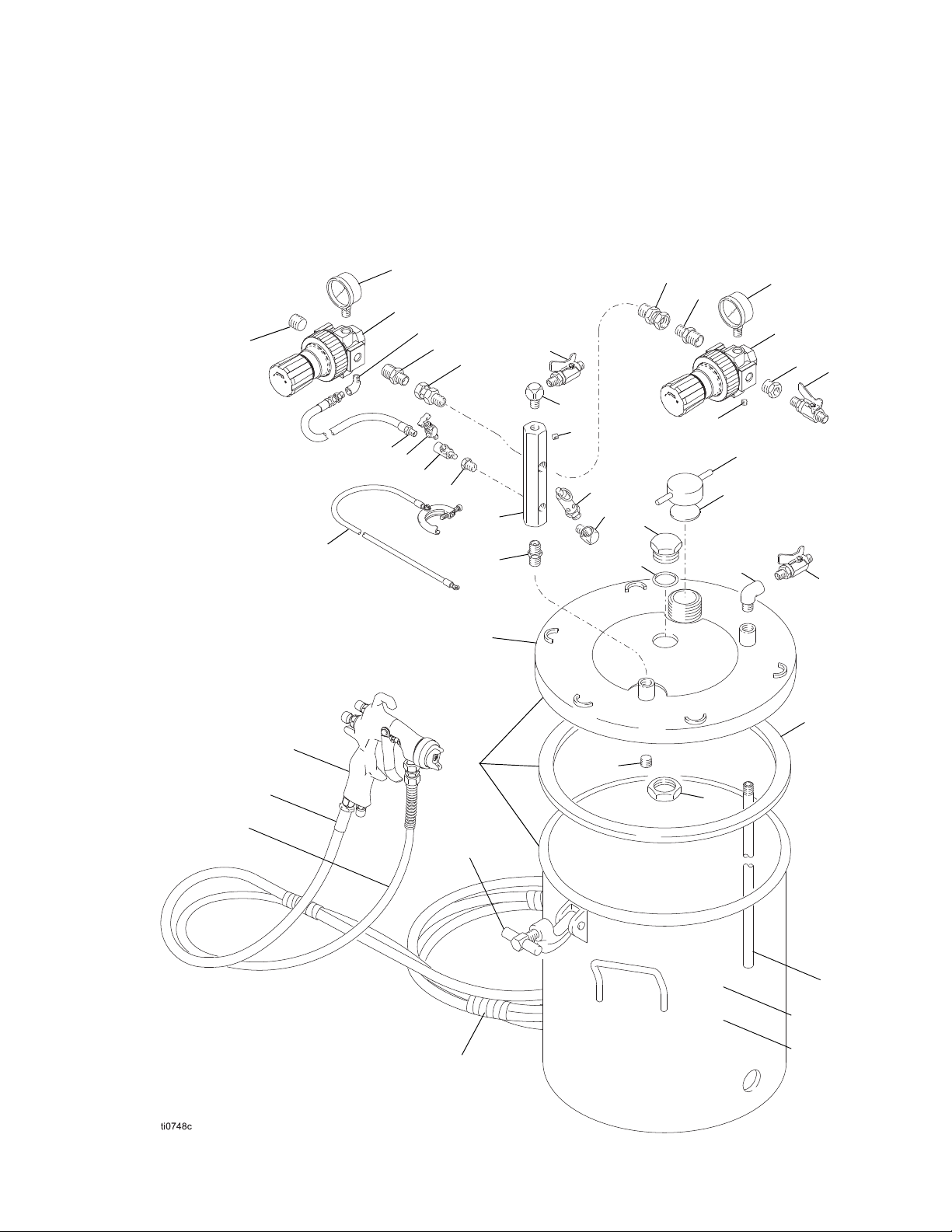
Parts
37
33
36
1
13
5
23
27b, 27c*
27
42
43
40
9
38
39
39
37
38
35
17
14
3
7
11
8
17
2
19
4
2
32
20
15
30
31
18
16
27a
6
22
12
10
21
44
* Torque to 8-10 ft-lbs
Parts
Model 237409, Series B
Includes items 1 to 44
14
Page 15

237409 Series B - Parts List
Parts
Ref.
No. Part No. Description Qty.
1 100361 PLUG 1
2 100840 ELBOW, street, 1/4-18 npt(m x f) 2
3 164724 HOSE, coupled, 1/8-27 npt(m) 1
4 103347 PRESSURE RELIEF VALVE, 100
psi (0.7 MPa, 7 bar), 1/4-18 npt(m)
5 189016 AIR INLET MANIFOLD,
3/8-18 npt x 1/4-18 npt
6 112306 PLUG, pipe, 3/8-18 npt 1
7 101759 AIR RELIEF VALVE 1
8 100030 BUSHING, 1/8-27 npt(f x m) 1
9 112538 ELBOW 1
10 176347 LABEL, identification 1
11 110475 TEE, street, 1/8-27 npt(f x m) 1
12 171976 TUBE, 5 gal. (20 liter) size, 1
13 222011 GROUND WIRE & CLAMP 1
14 156849 NIPPLE, pipe, 3/8-18 npt 1
15 171988 GASKET, chlororene rubber and
cork
16 110756 ELBOW, street, 90°, 3/8 npt (mxf) 1
17 208390 BALL VALVE, 1/4-18 npt(m)
See 307068 for parts
18 237533 BALL VALVE, 3/8-18 npsm(m x f),
See 307068 for parts
19 100139 PLUG, pipe, headless,1/8-27 npt 1
20 210575 CAP, filler 1
21 290044 LABEL, identification 1
22 188784 NUT, jam, hex, 1-1/2-12-unf-2b, 1
23 175078 LABEL, Warning, not shown 1
26 15D059 PRESSURE POT LINERS, Pack-
age of 20, 5 gal. (20 liter) size, pur-
chase separately
Ref.
No. Part No. Description Qty.
27 236087 PRESSURE POT, 5 gal (20 liter),
Includes replaceable items 27a to
27c
27a 117571 GASKET, Santoprene® 1
1
27b 111381 C- CLAMP KIT
1
27c 110143 T-HANDLE 6
30 188880 PLUG, lid 1
31 103414 O-RING, packing, fluoroelastomer 1
32 100721 PLUG, pipe, 3/8-18 npt 1
33 104267 AIR REGULATOR 1
35 100206 BUSHING 1
36 104267 AIR REGULATOR 1
37 160430 AIR PRESSURE GAUGE 2
38 159239 NIPPLE 2
39 155665 SWIVEL 2
40 235339 HOSE, fluid, nylon,
42 288931 AIR SPRAY GUN, conventional,
2
43 210867 AIR HOSE, cpld 1/4 npsm(fbe),
1
44 103473 WIRE TIE STRAP 13
Use only Genuine Graco Parts and Accessories.
Keep these spare parts on hand to reduce down
time.
Replacement Danger and Warning labels, tags
and cards are available at no cost.
includes item 27c
cpld 3/8 npsm (fbe),
1/4” ID x 25’(6.3 mm ID x 7.6 m)
AirPro; See manual 312414
5/16” ID x 25’ (7.9 mm ID x 7.6 m)
6
1
1
1
15
Page 16

Parts
34
36
33
13
5
23
27b, 27c*
27
42
43
40
9
39
37
38
35
17
14
3
7
11
8
17
2
19
4
2
32
20
15
30
31
18
16
27a
6
22
12
10
21
44
25
1
* Torque to 8-10 ft-lbs
Model 237413, Series A
Includes items 1 to 44
16
Page 17

237413 Series A - Parts List
Parts
Ref.
No. Part No.Description Qty.
1 110476 ADAPTER, union, straight swivel,
3/8 npt(m) to 1/4 npsm(f)
2 100840 ELBOW, street, 1/4-18 npt(m x f) 2
3 164724 HOSE, coupled, 1/8-27 npt(m) 1
4 103347 PRESSURE RELIEF VALVE,
100 psi (0.7 MPa, 7 bar),
1/4-18 npt(m)
5 189016 AIR INLET MANIFOLD,
3/8-18 npt x 1/4-18 npt
6 112306 PLUG, pipe, 3/8-18 npt 1
7 101759 AIR RELIEF VALVE 1
8 100030 BUSHING, 1/8-27 npt(f x m) 1
9 112307 ELBOW, street, 90°,
1/8-27 npt (f x m)
10 176347 LABEL, identification 1
11 110475 TEE, street, 1/8-27 npt (f x m) 1
12 171976 TUBE, 5 gal. (20 liter) size 1
13 222011 GROUND WIRE & CLAMP 1
14 156849 NIPPLE, pipe, 3/8-18 npt 1
15 171988 GASKET, chlororene rubb er and cork 1
16 110756 ELBOW, street, 90°, 3/8 npt (mxf) 1
17 208390 BALL VALVE, 1/4-18 npt(m)
See 307068 for parts
18 237533 BALL VALVE, 3/8-18 npsm(m x f),
See 307068 for parts
19 100139 PLUG, pipe, headless,1/8-27 npt 1
20 210575 CAP, filler 1
21 290044 LABEL, identification 1
22 188784 NUT, jam, hex, 1-1/2-12-unf-2b, 1
23 175078 LABEL, Warning, not shown 1
25 151519 NIPPLE, reducing, 1/4-1/8 npt 1
26 15D059 PRESSURE POT LINERS,
Package of 20, 5 gal. (20 liter) size,
purchase separately
Ref.
No. Part No.Description Qty.
27 236087 PRESSURE POT, 5 gal (20 liter),
1
Includes replaceable items
27a to 27c
27a 117571 GASKET, Santoprene
27b 111381 C-CLAMP KIT includes item 27c 6
1
® 1
27c 110143 T-HANDLE 6
30 188880 PLUG, lid 1
31 103414 O-RING, packing, fluoroelastomer 1
1
32 100721 PLUG, pipe, 3/8-18 npt 1
33 111501 AIR REGULATOR, 0-15 psi
(0-103 kPa, 0-1 bar)
34 110444 AIR PRESSURE GAUGE 0-15 psi
1
(0-103 kPa, 0-1 bar)
35 100206 BUSHING 1
36 104267 AIR REGULATO R 1
37 160430 AI R PRESSURE GAUGE 1
38 159239 NIPPLE 1
39 155665 SWIVEL 1
40 235339 HOSE, fluid, nylon, cpld 3/8 npsm
(fbe), 1/4” ID x 25’
(6.3 mm ID x 7.6 m)
42 288938 HVLP GUN, AirPro
2
See manual 312414
43 210867 AIR HOSE, cpld 1/4 npsm(fbe),
1
5/16” ID x 25’ (7.9 mm ID 1 x 7.6 m)
44 103473 WIRE TIE STRAP 13
Use only Genuine Graco Parts and Accessories.
Keep these spare parts on hand to reduce down
time.
Replacement Danger and Warning labels, tags and
1
cards are available at no cost.
1
1
1
1
1
1
17
Page 18

Technical Specifications
Technical Specifications
Maximum Fluid Working Pressure 100 psi 0.7 MPa, 7 bar
Maximum Air Working Pressure 100 psi 0.7 MPa, 7 bar
Gun Air Consumption See manual 312414
Actual Pot Capacity
Wetted Parts
Pressure pot 304/316 stainless steel ASME, Santoprene
Spray gun See manual 312414
Fluid hoses nylon
Fluid fittings 304/316 stainless steel
Notes
All 304, 316 and 17-4 PH stainless steel is electropolished and/or passivate d.
Santoprene® is a registered trademark of the Monsanto Co.
US Metric
8.8 U.S. gallon
thermoplastic polyamide, and PET
33 liter
®
,
California Proposition 65
CALIFORNIA RESIDENTS
WARNING: Cancer and reproductive harm – www.P65warnings.ca.gov.
18
Page 19

Notes
Notes
19
Page 20

Graco Standard Warranty
Graco warrants all equipment referenced in this document which is manufactured by Graco and bearing its name to be free from defects in
material and workmanship on the date of sale to the original purchaser for use. With the exception of any special, extended, or limited warranty
published by Graco, Graco will, for a period of twelve months from the date of sale, repair or replace any part of the equipment determined by
Graco to be defective. This warranty applies only when the equipment is installed, operated and maintained in accordance with Graco’s written
recommendations.
This warranty does not cover, and Graco shall not be liable for general wear and tear, or any malfunction, damage or wear caused by faulty
installation, misapplication, abrasion, corrosion, inadequate or improper maintenance, negligence, accident, tampering, or substitution of
non-Graco component parts. Nor shall Graco be liable for malfunction, damage or wear caused by the incompatibility of Graco equipment with
structures, accessories, equipment or materials not supplied by Graco, or the improper design, manufacture, installation, operation or
maintenance of structures, accessories, equipment or materials not supplied by Graco.
This warranty is conditioned upon the prepaid return of the equipment claimed to be defective to an authorized Graco distributor for verification of
the claimed defect. If the claimed defect is verified, Graco will repair or replace free of charge any defective parts. The equipment will be returned
to the original purchaser transportation prepaid. If inspection of the equipment does not disclose any defect in material or workmanship, repairs will
be made at a reasonable charge, which charges may include the costs of parts, labor, and transportation.
THIS WARRANTY IS EXCLUSIVE, AND IS IN LIEU OF ANY OTHER WARRANTIES, EXPRESS OR IMPLIED, INCLUDING BUT NOT LIMITED
TO WARRANTY OF MERCHANTABILITY OR WARRANTY OF FITNESS FOR A PARTICULAR PURPOSE.
Graco’s sole obligation and buyer’s sole remedy for any breach of warranty shall be as set forth above. The buyer agrees that no other remedy
(including, but not limited to, incidental or consequential damages for lost profits, lost sales, injury to person or property, or any other incidental or
consequential loss) shall be available. Any action for breach of warranty must be brought within two (2) years of the date of sale.
GRACO MAKES NO WARRANTY, AND DISCLAIMS ALL IMPLIED WARRANTIES OF MERCHANTABILITY AND FITNESS FOR A
PARTICULAR PURPOSE, IN CONNECTION WITH ACCESSORIES, EQUIPMENT, MATERIALS OR COMPONENTS SOLD BUT NOT
MANUFACTURED BY GRACO. These items sold, but not manufactured by Graco (such as electric motors, switches, hose, etc.), are subject to
the warranty, if any, of their manufacturer. Graco will provide purchaser with reasonable assistance in making any claim for breach of these
warranties.
In no event will Graco be liable for indirect, incidental, special or consequential damages resulting from Graco supplying equipment hereunder, or
the furnishing, performance, or use of any products or other goods sold hereto, whether due to a breach of contract, breach of warranty, the
negligence of Graco, or otherwise.
FOR GRACO CANADA CUSTOMERS
The Parties acknowledge that they have required that the present document, as well as all documents, notices and legal proceedings entered into,
given or instituted pursuant hereto or relating directly or indirectly hereto, be drawn up in English. Les parties reconnaissent avoir convenu que la
rédaction du présente document sera en Anglais, ainsi que tous documents, avis et procédures judiciaires exécutés, donnés ou intentés, à la suite
de ou en rapport, directement ou indirectement, avec les procédures concernées.
Graco Information
For the latest information about Graco products, visit www.graco.com.
For patent information, see www.graco.com/patents.
TO PLACE AN ORDER, contact your Graco distributor or call to identify the nearest distributor.
Phone: 612-623-6921 or Toll Free: 1-800-328-0211 Fax: 612-378-3505
All written and visual data contained in this document reflects the latest product information available at the time of publication.
GRACO INC. AND SUBSIDIARIES • P.O. BOX 1441 • MINNEAPOLIS MN 55440-1441 • USA
Copyright 1994, Graco Inc. All Graco manufacturing locations are registered to ISO 9001.
Graco reserves the right to make changes at any time without notice.
Original instructions. This manual contains English. MM 308455
Graco Headquarters: Minneapolis
International Offices: Belgium, China, Japan, Korea
www.graco.com
Revision N, December 2020
 Loading...