

Page 1
INSTRUCTIONS-PARTS
LIST.
308-201
This
manual
WARNINGS
READ
AND
contains
AND
RETAIN
IMPORTANT
INSTRUCTIONS
FOR
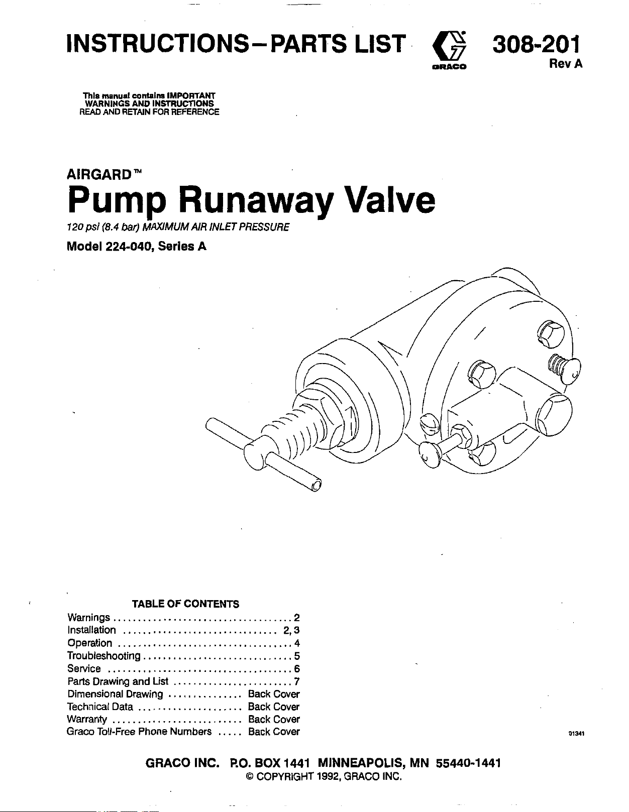
AIRGARD"
Pump
120
psi
(8.4
bar)
kXlMUM
Model
224-040,
Series
REFERENCE
Runaway
AIR
INLET
PRESSURE
A
w
0-
Valve
Rev
A
TABLE
Warnings.. .................................
Installation
Operation
Troubleshooting..
Service
Parts Drawing and List
Dimensional Drawing
Technical Data
Warranty Back Cover
Graco Toll-Free Phone Numbers Back Cover
...............................
..................................
....................................
..........................
OF
CONTENTS
...........................
.......................
...............
Back Cover
..................... Back Cover
.....
GRACO INC.
P.0.
BOX
0
COPYRIGHT
.2
2,3
.4
.5
.6
.7
1441 MINNEAPOLIS, MN 55440-1441
1992,
GRACO INC.
Page 2
OBSERVE ALL WARNINGS. Read And Understand All Instruction Manuals Before Operating Equipment.
Use Only With Compressed Air
This valve is for useonfywithcompressedair. It is not designed
for use with any other power source. NEVER use any other gas
or fluid in the runaway valve.
General Safety
Any misuse of the runaway valve, such as overpressurizing,
modifyingparts,orusingwomordamagedparts,cancausethe
valveto ruptureand result inseriousinjuryorpropertydamage.
NEVER alter or modify any part of the runaway valve; doing so
could cause it to malfunction.
CHECK all equipment regularly and repair or replace worn or
damaged parts immediately.
Moving Parts Hazard
To reduce the risk of serious injury, including pinching or am-
putationoffingersorhands, NEVERusetherunawayvalveasa
pump shutoff vaNe. The valve does not completely shut off the
airsupply,and thepumpwillcontinuetooperateslowlyafterthe
valve closes. The air motor piston (located behind the air motor
platesorshield) moveswhenairissuppliedtothemotor.NEVER
operate the pump wlth the air motor plates or shield removed.
System Pressure
NEVER exceed 120 psi (8.4 bar) MAXIMUM AIR INLET PRES-
SURE to the vaive, or the maximum air inlet pressure stated on
your pump.
DONOTexceedthemaximumworkingpressureofanycomponent or accessory used in the system.
Pressure Relief Procedure
To reduce the risk of serious injury, includin injury from
Alwayswearprotectiveeyewear,gloves,clothingandrespirator
as recommended by the fluid and solvent manufacturer.
Alwaysfollowthe Pressure Relief Procedureinyourseparate
pump manual, before checking, clearing, cleaning, flushing or
servicing any part of the system.
moving parts, alwaysfollowthisprocedurew
are servicing the runaway valve.
1. Follow the Pressure Relief Procedure in your separate pump manual.
2. Shut off the main air shutoff valve.
3,
eneveryou
IMPORTANT
United States Government safety standards have been adopted under the Occupational Safety and Health Act. These standards -
particularly the General Standards, Pati1910, and the Construction Standards, Part 1926 - should be consulted.
INSTALLATION
Reference letters and numbers in the text refer to Figs 1
and 2 and the Parts Drawing on page 7.
Install an air filter (A) to remove harmful dirt and moisture
from the compressed air supply. Install a main air shutoff
valve (6) to isolate the runaway valve for servicing. If you
supply your own accessories, be sure they are adequately sized and pressure-rated to meet the system’s
requirements.
The Typical Installations shown on page 3 are only examples Contact your Grace representative or Grace
Technical Assistance (see back page) for assistance in
designing a system to meet your particular needs.
install one runaway valve for each pump; the valve will
control only one pump.
WARNING
A bleed-type master air valve (C) is required in
your system. The bleed-type master air valve re-
lieves air trapped between this valve and the pump
after the air is shut off. Trapped air can cause the
pump to cycle unexpectedly. Locate the valve
close to the pump.
2 308-201
Installing the Runaway Valve on King’“, Bulldoge,
and Senatore Motors
Detail Aof Fig 1 shows the runaway valve (D) used with a
Bulldoge air motor, mounted on a cart. Mounting on a
wall bracket is done the same way. Install the runaway
valve between the air manifold (E) and the air regulator
(F), using necessary adapters. Use the 90” swivel
adapter (G, supplied) to connect the runaway valve outlet to the air regulator inlet.
lnstalltng the Runaway Valve on Presidente Motors
Details B and C of Fig 1 show the runaway valve (D)
used with a Presidente air motor, mounted on a wall and
on a cart. Install the runaway valve between the air regu-
lator (F) and the bleed-type master air valve (C), using
necessary adapters. Use the 90” swivel adapter (G,
supplied) to connect the runaway valve outlet to the
bleed valve inlet.
Signal Port (See Fig 2)
When the runaway valve trips, the signal port (S) is pres-
surized. This air pressure will operate a pilot-operated
valve to turn on a remote device such as a signal lamp or
alarm. The pressure at this port will be 15% less than the
inbound air pressure. The volume ofairpassing through
the port will be low.
When no remote sensor is being used, this port is
plugged with a screw (3).
Page 3

TYPICAL INSTALLATIONS
KEY
A Air Line Filter
B
C
D
E
F
Q
RECOMMENDED ADAPTERS
Main Air Shutoff Valve
Bleed-Type Master
(required, for pump)
Pump Runaway Valve
Air Manifold
Air Regulator
Runaway Valve Swivel (supplied)
Air
Valve
DETAIL
175-013
157-191 Reducer: 314 npt
160427 Swivel Adapter;
B
(WALL-MOUNTED DETAIL C (CART-MOUNTED
MAIN AIR
B
LIN
PRESIDENT AIR MOTOR)
Nipple: 314 npt
314 npt(m)
x
112
x
314 npsm(f)
npt
/
Fig 1
c
308-201
01267
3
Page 4

CAUSES
Pump runaway refers to a rapid acceleration in pump
speed, which can result in serious damage to the pump
parts caused by overheating and scoring. Conditions
which can cause pump runaway are:
The fluid supply container is empty, or the fluid supply
has been interrupted.
The pump is cavitating, which means that it has lost its
prime because an air pocket has formed around the
pump intake. This happens most frequently with highly viscous fluids.
Afluid hose downstream from the pump has ruptured,
resulting in an increased pump cycle rate.
NOTE:
When in a runaway condition, the pump requires much
more air than during normal operation. The runaway
valve senses this rapid increase in the volume of air being .used and greatly reduces the air flow, slowing the
pump to a crawl.
NOTE:
ADJUSTING THE VALVE
1.
2.
3.
OF
A RUNAWAY PUMP
The runaway valve may also trip if changes to
the system result in an increased cycle rate. For
if
example,
drops, you should readjust the valve to account
for the increased cycle.rate.
The sudden surge of air when starting the pump
may cause the valve to trip. Turn on the air slowly, or readjust the valve.
Loosen the adjustment locknut (24). See Fig 2.
Check that the T-handle (2)
counterclockwise.
Open the dispensing valve or trigger the spray gun.
you increase the number of gun
is
turned all the way
NOTE A faint hissing sound from the runaway valve
normal. The valve vents a small amount of air
from the poppet vent
5.
Adjust the pump to the desired regulated air pres-
sure and cycle rate.
6.
Turn the T-handle
valve trips. Press and hold the RESETvalve
will feel pressure on the RESET valve. Turn the handie (2) counterclockwise (approximately
turns) until pressure on the RESET valve decreases.
Release the RESET valve.
NOTE:
7.
8.
TESTING THE VALVE
To test the runaway valve, press the TEST valve
runaway valve should trip. Start the pump by pressing
the RESET valve
RESETTING THE VALVE
1.
2. If the air was shut
3.
At low pressure or a slow cycle rate, perform
step
6, then turn theT-handle (2) clockwise un-
til
you feel a slight pressure pushing on the RESET valve
counterclockwise distance
take several tries to achieve the proper setting.
Tighten the locknut (24).
Test the runaway valve as described in the following
paragraph.
Determine the condition that caused the runaway
valve to trip. Correct the condition.
den surge of air will cause the runaway valve to trip.
Press the RESET valve
conds. The pump should restart.
(2)
(R).
(R)
and holding it
off,
(H)
during operation.
clockwise until the runaway
(Turn it approximately half the
in
step
6.)
This may
in
for 5 seconds.
turn it back on slowly. A sud-
(R)
and hold it in.for 5 se-
(R);
1
0.
you
to
The
is
5
4.
Slowly open the main air shutoff valve
Fig
4
regulator
(C).
2
308-201
(F),
See Fig
2
and the bleed-type master air valve
1.
(B),
the air
NOTE:
In some installations, particularly where there is
low air volume, it may be necessary to turn off
the air supply to reset the valve.
01263
Page 5

I
PROBLEM
I
CAUSE
TROUBLESHOOTING
I
SOLUTION
CHART
Valve does not slow down
It
pump when
pump runs away
should;
Valve is not adjusted properly. Readjust valve and test.
Ruptured diaphragm. (If diaphragm is rup-
tured,
Decreased air pressure
speed
Poppet valve
of
Constant blast
vent when air supply is
turned on.
Valve shuts down for no
apparent reason
air from
Poppet valve
Increased air pressure has caused pump
speed
Interrupted or exhausted fluid supply. Check fluid supply and ensure that
Valve is not adjusted properly.
Decreased pump outlet pressure.
Air supply was turned on
,
Air leaking around
the
TEST
bunon will have no
to decrease.
(11, 14, 15)
(1 1, 14, 15)
to
increase.
Defective poppet valve.
TEST
effect.)
has
caused pump
is stuck closed.
is stuck open.
too
quickly.
valve. Replace
See
page
4.
Replace the diaphragm.
Readjust valve and test.
Disassemble and clean valve. Replace O-rings. Piston is stuck.
See
page
6.
Disassemble and clean poppet valve.
Disassemble and clean poppet valve.
Readjust valve and
Readjust valve and test.
Check for properly adjusted fluid outlet pressure.
Check and repair.
Press
RESET
valve.
TEST
valve.
test.
See
See
See
See
See
page
page
6.
page
4.
page
4.
it
remains constant.
page
4.
6.
See
See
page 6.
page
6.
Valvedoesnotresetwhen
RESET
valve is pressed
1
~ Piston is stuck; no air is escaping from vent. Disassemble and clean runaway valve.
Alr blowing from poppet vent.
Valve is not adjusted properly. Readjust valve and test.
Poppet vent hole plugged.
Remove
See
I
I
Disassemble and clean poppet valve.
RESET
page
valve. Clean needle and seat area.
6.
See
page
4.
See
See
page
page
6.
6.
308-201
5
Page 6

SERVICE
TOOLS REQUIRED
.
IO mm socket wrench
.
t 1 I1 6” socket wrench
.
Adjustable wrench
.
Torque wrench
.
I” crow%-foot
.
I//;;;3 mm) brass rod, or a press
.
.
Small needle-nose pliers
.
O-ring pick
.
Thread lubricant
DISASSEMBLY (See the Parts Drawing on page 7)
NOTE: Reoair Kit 224-937 is available to service the dia-
phiagm and o-rings. For best results, use all
parts in the kit. Parts included in the kit are
marked with an asterisk (for example, 4*).
l. Follow the Pressure Relief Procedure Warning in
your separate pump manual. Shut off the main air
valve. Tighten the locknut (24) to lock the valve at its
current adjustment. Remove the runaway valve
from the air line.
2. Place the valve in a vise with the T-handle (2) facing
left and the poppet valve cap (25) facing upward.
Unscrew the adapter (34) from the valve outlet.
3. Using an adjustable wrench on the flats, unscrew
the stem guide (17) from the lower housing (22).
The adjustment screw (21) will come free with the
stem guide and connecting parts.
4. Reach into the valve outlet and push out the piston
(16). Remove the o-rings (6,36) from the piston.
NOTE: The TEST valve assembly is also press-fit lo-
gether. Do not disassemble it unless it is leaking
and the parts require replacement.
12. Clean all parts and inspect for damage. Se sure to
clean all air passages, cavities, and surfaces.
REASSEMBLY (See the Parts Drawing on page 7)
1.
Place the upper housing (23) in a vise. Install the RESET valve In the upper housing. Tighten the valve
housing (19) to secure.
2.
Install the diaphragm (27’) in the lower housing (22)
so the larger center plate of the diaphragm is facing
outward. Align the four large holes in the diaphragm
with the four threaded holes in the housing.
3.
Lubricate the dowel pin (6). Working from the inside
of the upper housing (23), insert the pin (6) into the
small center hole. Push the pin all the way in, so it is
flush with the surface of the housing.
4.
Place the lower housing (22) in a vise. Position the
upper housing (23) so the boss (marked RESET) is
oriented as shown, and the four holes are aligned
with the holes in the diaphragm (27) and lower
housing (22). Assemble the two housings using the
four screws (9) and lockwashers (I). Using a 10 mm
socket wrench, torque to 50-70 in-lb (5.6-7.9 N.m).
5.
Lubricate the o-ring (4*) and install it on the push pin
(15). Install the valve poppet (14,) on the barbed
end of the push pin. Insert these parts into the cen-
ter hole of the upper housing (23), with the poppet
(14) facing outward.
5. Insert a brass rod into the valve outlet so it contacts
the valve body (16). Tap the rod with a mallet to unseat the valve body. (This can also be done with a
press.) Push the valve body out of the housing (22).
6.
Remove the o-rings (5, 7) from the valve body (16).
Remove the gasket (13) from ih& housing (22).
7.
Using an 1 l/16” socket wrench, loosen but do not
remove the cap (25) from the upper housing (23).
a.
Using a IO mm socket wrench, remove the four
screws (9) .and lo&washers (I). Pull the upper
housing (23) away from the lower housing (22). Re-
move the diaphragm (27).
9.
Unscrew the cap (25) from the upper housing (23).
Remove the gasket (IO) from the cap. Remove the
poppet valve spring (1 I). Push down on the poppet
so the dowel pin (6) protrudes from the hole on the
inside of the housing (23).
10,
Remove the poppet (14), push pin (15), and o-ring
(1) from the upper housing (23). Working on the inside of the housing (23), grasp the dowel pin (6) with
a needle-nose pliers and pull it.out of the housing.
11.
Unscrew the valire housing (19) and pull the RESET
valve assembly out of the upper housing (23).
6.
Install the spring (Ii*) in the upper housing (23) and
seat it on the poppet (14). Install the gasket (IO*) on
the spring retainer cap (25). Apply thread sealant to
the threads of the retainer cap. Screw the cap into
the housing using an 11/16” socket wrench, and
torque to 50-70 in-lb (5.6-7.9 N.m).
7.
Install the gasket (13*) into the lower housing (22),
making sure it seats on the inside shoulder.
a.
Lubricate the two o-rings (5*, 7*). Install the larger
o-ring (5*) in the outside groove of the valve body
(I@, and the smaller o-ring (7*) in the inside groove.
Slide the valve body into the lower housing (22),
with the end holding the o-rings facing intd the
housing. Use a brass rod and mallet (or a press) to
seat the valve body securely in the housing.
9.
Install the two o-rings (6*, 36’) in the grooves of the
piston (16). Slide the piston into the valve body (16),
with the narrow end facing inward. Push the piston
into the valve body as far as it will go.
10. Turn the adjustment screw (21) all the way counterclockwise, then install it and the stem guide (17) in
the lower housing (22). Use a 1” crow’s-foot to
torque the guide to 20-30 R-lb (27-41 N.m). so its
shoulder is flush with the surface of the housing.
NOTE: The RESET valve assembly is press-fit together.
Do not disassemble it unless the needle (20) or
valve housing (19) require replacement.
6 308-201
11. Screw the adapter (34) into the valve outlet. Reinstall the runaway valve inthe air line. Adjust and test
the valve as described on page 4.
Page 7

Model 224-040, Series A
PTFE
Includes items l-36
DESCRIPTION QN
PARTS DRAWING AND LIST
: : Ei::
3 103-962
4 104-007*
104-010*
105-399*
z
7 105~400*
: 105-402 111.667
LOCKWASHER. spring; l/4”
PIN. spring, straight
SCRMI, machine, pan hd;
1032 unf-2a; 0.312” (7.9 mm) long
O-RING; bun&N
O-RING; buna-N
O-RING; nitrile
O-RING; buna-N
PIN, dowel
SCREW. cao. hex hd: M6 x 1:
20 mm lbnrj'
10 150451’
:: 156-916’ 156-920
:: 166-601’
169-216*
15 176-671
;; 166-706 166-707
:: 1 ;g::;:
:: 166-711 166710
$Z 166-714 166-713
24 167-545
;: 167-549
224-945*
:: 166-l 157626 02
34 160-327
36 111-027’
l included in Repair Kit 224-937.
GASKET: copper
SPRING, compression
PUSHBUTTON
GASKET;
POPPET valve
PIN, push
BODY, valve
;,UIDIDkstem
HOUSING. valve
NEEDLE, valve
SCREW, adjustment
HOUSING, valve, lower
HOUSING, valve, upper
NUT, {am, hex; Q/4-32 un-2b
;;“f;prina;tatner
NEEDLE, valve
O-RING
ADAPTER, swivel;
3/4 npt(m) x 3/4 npsm(fJ
O-RING; buneN
SEALANT AND
TORQUETO
5070 In-lb
j”
17
TORQUE TO
20-30 n-lb
(27-41 N.m)
\
24
/ m -AIR OUTLET
AIR INLET
308-201 7
Page 8

DIMENSIONAL DRAWING
Maximum air input pressure ............. 120 psi (8.4 bar)
Air pressure range ................ 20-120 psi (1.4-8.4 bar)
I
\
t-
rrrr
11111
Airvolume range ............ .5-250 cfm (0.14-7.0 m3/min)
Air inlet ..................................... 314 notffl
Air outlet . . Without swivel attached: 3i4 npt(c
Weight . Wilfioutswivelaffached: 2 lb 5 oz (1.05 kg);
TECHNICAL DATA
With swivel attached: 3/4 npsm(f)
With swivel affached: 3 lb (1.36 kg)
I
314 NM(F) INLET
THE GRACO WARRANTY AND DISCLAIMERS
WARRANN
Gracowarrantsallequipmentmanufaoturedb
of sale by an authorized Grace distributor tot K ”
Gracowill,foraperiodoftwelvemonthsfromthedateofsale,repairorreplaceanypartoftheequipmentprovendefective.Thiswarranty
applies only when the equipment is installed, operated and maintained in accordance with Grace’s written recommendations.
itand bearingitsnametobefreefromdefectsinmaterialandworkmanshiponthedate
e ongmal purchaser for use. As purchaser’s sole remedy for breach of this warranty,
Thiswarrantydoesnotcover,andGracoshallnotbeliablefor,anymalfunction,damageorwearcaused byfaultyinstallation,misapplication,abrasion,corrosion,inadequateorimpropermaintenance,negligence,acciden!.tampering,orsubstitutionofnon-Gracocomponent parts. NorshallGraco beliableformalfunction,damageorwearcaused bythetncompatibrlitywithGracoequipment ofstructures,accessories,equipmentormaterialsnotsuppliedbyGraco,ortheimproperdesign,manufacture,installation,operationormaintenance of structures, accessories, equipment or materials not supplied by Graoo.
This warranty is conditioned upon the prepaid return of the equipment claimed to be defectiveto an authorized Grace distributor for
verificationoftheclaim.Iftheclaimeddefectisver%ed,Gracowillrepairorreplacefreeofchar eanydefectivepatis.Theequipmentwiil
be returned tothe original purohasertransportatlon prepaid. If inspection ofthe equipment 3 08s not disclose any defect in material or
workmanship, repairs will be made at a reasonable charge, which charges may include the costs of parts, labor and transportation.
DISCLAIMERS AND LIMITATIONS
THETERMSOFTnlSWARRANMCONS~PURGHASER’SSOLEANDWCLUSNEREMEDYANDAREINUEUOFANYOTHERWARRANTlES
(EXPRESS OR IMPUED). INCLUDING WARRANTYOF MERCHANTABILRYOR WARRANTYOF FITNESS FOR A PARTICULAR PURPOSE, AND OF
ANY NON-CONTRACTUAL LiABILtTIES, INCLUDING PRODUCT LIABILITIES, BASED ON NEGUGENCE OR STRICT UABIUTY. EVERY FORM OF
LIABILITY FOR DIRECT. SPECIAL OR CONSEQUENTtAL DAMAGES OR LOSS IS EXPRESSLY EXCLUDED AND DENIED. IN NO CASE SHALL
GRACO’SLlABlUNEXCEEOTHEAMOUNTOFTHEPURCHASEPRICE.ANYACTlONFORBREACHOFWARRANNMUSTBEBROUGHTWlTHlN
MI0 (2) YEARS OFTHE DATE OF SALE.
EQUIPMENT NOT COVERED BY GRACO WARRANN
GFiACO MAKES NO WARRANTY AND DISCWMS AU IMPLIED WARRANTIES OF MERCHANTABIUTYAND FITNESS FOR A PARTICULAR PUR-
POSE, WITH RESPECTTOACCESSORIES, ECUIPMENT, MATERIALS, OR COMPONENTS SOLD BUT NOT MANUFACTURED BY GRACO. These
itemssold. butnotmanufacturedbyGraco(suchaselectricmotor,switches. hose,etc.)aresubjecttothewarranty,ifany,oftheirmanu-
facturer. Graoo will provide purchaser with reasonable assistance in making any claim tor breach of these warranttes.
IMPORTANT PHONE NUMBERS
TO PLACE AN ORDER, contact your Grace distributor, or call
this number to identify the distributor closest to you:
1-800-329-0211 Toll Free
FOR TECHNICAL ASSISTANCE, service repair information or
assistance regarding the application of Grace equipment:
l-900-9439339 Toll Free
Factory Branches: Atlanta, Chicago, Dallas, Detroit, Los Angeles, Mt. Arlington (N.J.)
Subsidiary and Affiliate Companies: Canada: England; Switzerland; France; Germany; Hong Kong; Japan; Korea
GRACO INC. RO. BOX 1441 MINNEAPOLIS, MN 55440-1441
PRINTED IN U.S.A. 30820, es2
 Loading...