

Setup and Operation
Important Safety Instructions
Read all warnings and instructions in this manual
and all related manuals before using this
equipment. Save these instructions.
3A5856A
PROVEN QUALITY. LEADING TECHNOLOGY.
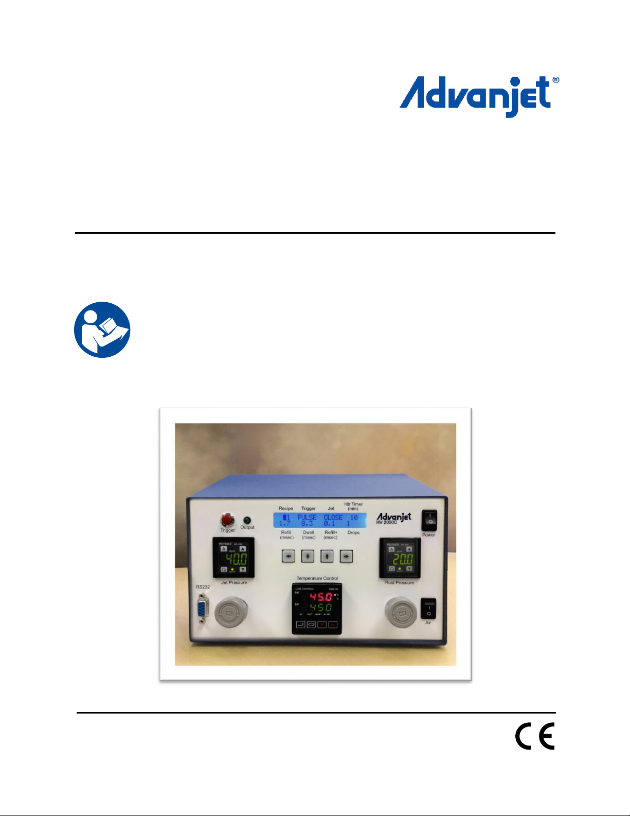
HV-2000C Jet
Controller
Diaphragm-Jet™ Technology EN
For controlling non-contact dispensing of viscous material in industrial
environments. For Professional Use only.

Table of Contents
RELATED MANUALS .................................................................................................... 4
SAFETY GUIDELINES ................................................................................................... 5
1. INTRODUCTION AND SPECIFICATIONS .......................................................... 6
1.1 Advanjet HV-2000/2000C Overview ............................................................ 6
1.2 HV-2000C Controller Specifications ............................................................. 7
1.3 Technical Assistance ................................................................................... 7
1.4 HV-2000C Controller Dimensions ................................................................ 8
1.5 HV-2000C Front and Rear Features ............................................................ 9
2. INSTALLATION AND SETUP ............................................................................ 10
2.1 Physical Placement .................................................................................... 10
2.2 Pneumatic System ..................................................................................... 10
2.3 Electrical Interface ..................................................................................... 11
2.4 Input / Output Connections ........................................................................ 12
3. USING THE HV-2000C CONTROLLER FRONT PANEL .................................. 13
3.1 Jet and Fluid Pressure Regulators ............................................................. 13
3.2 Temperature Controller .............................................................................. 14
3.3 Trigger Button and LED ............................................................................. 15
3.4 LCD Display and Selection Keys ............................................................... 16
3.5 Jet Setting from the Front Panel ................................................................ 16
3.6 Special Front Panel Key Sequences .......................................................... 18
4. RS-232 COMMUNICATION ............................................................................... 19
4.1 RS-232 Connector Pins ............................................................................. 19
4.2 Changing the Default RS-232 Settings ...................................................... 20
5. ADVANJET SOFTWARE ................................................................................... 21
5.1 Installing and Starting Up the Software ...................................................... 21
5.2 Settings Menu ............................................................................................ 22
5.3 Running a Program from Software ............................................................. 25
6. TIMING RECIPES .............................................................................................. 26
6.1 Timing Recipe Parameters ......................................................................... 26
6.2 Programming Timing Recipes .................................................................... 27
6.3 DROP Mode Programming ........................................................................ 29
Dispensing one drop at a time............................................................... 29
Dispensing multiple drop sizes .............................................................. 29
6.4 LINE Mode Programming ........................................................................... 30
Method 1: Jetting a line in PULSE mode ............................................... 30
Method 2: Jetting a line in LEVEL Mode ............................................... 30
Method 3: Jetting a line during an X-Y move......................................... 31
7. ADVANJET CONTROLLER COMMANDS (ACC) ............................................. 32
7.1 The RS-232 Interface ................................................................................. 32
7.2 Command Format ...................................................................................... 32
7.3 Recipe Timing Commands ......................................................................... 33
7.4 Jetting Commands ..................................................................................... 35
7.5 Heater Commands ..................................................................................... 37
Page 2 of 60 Advanjet HV-2000C Jet Controller Setup and Operation 3A5856A

Table of Contents
7.6 Output Commands ..................................................................................... 38
APPENDIX 1: FIRST DROP COMPENSATION........................................................ 39
Appendix 1-1: Background.............................................................................. 39
Appendix 1-2: Calculating First Drop Compensation ...................................... 39
Appendix 1-3: First Drop Compensation in PULSE Mode .............................. 40
Appendix 1-4: First Drop Compensation in LEVEL Mode ............................... 42
APPENDIX 2: TEMPERATURE CONTROLLER FACTORY SETTINGS ................. 43
APPENDIX 3: DIGITAL PRESSURE GAUGE .......................................................... 45
Appendix 3-1: Specifications ........................................................................... 45
Appendix 3-2: Part Names and Functions ...................................................... 46
Appendix 3-3: Connections and Input/Output Circuit ...................................... 47
Appendix 3-4: Operation Mode Selection ....................................................... 48
Appendix 3-5: Operation Mode Selection ....................................................... 49
Appendix 3-6: Adjustment ............................................................................... 50
Appendix 3-7: Other Functions and Error Indications ..................................... 51
APPENDIX 4: INPUT/OUTPUT CONNECTOR ......................................................... 52
Appendix 4-1: HD26 Pin Assignments ............................................................ 52
Appendix 4-2: Schematic for Configurable I/O DIO0-DIO31 ........................... 55
Appendix 4-3: Schematic for Buffered A/D Converter Inputs .......................... 56
Appendix 4-4: Schematic for D/A Converter Outputs ...................................... 57
Appendix 4-5: Schematic for Pressure Alarm Input/Output Circuit ................. 58
APPENDIX 5: REPLACING THE 24V DRIVER BOARD FUSE ................................ 59
GRACO STANDARD WARRANTY .............................................................................. 60
3A5856A Advanjet HV-2000C Jet Controller Setup and Operation Page 3 of 60

3A5855
HV-2000 Jet Setup and Operation
3A5908
Advanjet Jet Maintenance Tool Kit (JKT-2000)
3A5909
HV-2000 Maintenance and Repair
Related Manuals
Manuals are available at www.graco.com. Component manuals below are in English:
Page 4 of 60 Advanjet HV-2000C Jet Controller Setup and Operation 3A5856A
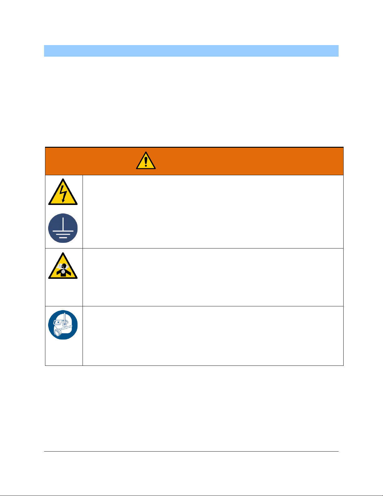
WARNING
ELECTRIC SHOCK HAZARD
This equipment must be grounded. Improper grounding, setup, or usage of the system can
cause electric shock.
• Turn off and disconnect power cord before servicing equipment.
• Connect only to grounded electrical outlets.
• Use only 3-wire extension cords.
• Ensure ground prongs are intact on power and extension cords.
• There are no user-serviceable components under the cover. Disconnect the power cord
and contact Advanjet if there is any desire to remove the cover.
TOXIC FLUID OR FUMES HAZARD
Toxic fluids or fumes can cause serious injury or death if splashed in the eyes or on skin,
inhaled, or swallowed.
• Read Safety Data Sheets (SDSs) to know the specific hazards of the fluids you are
using.
• Store hazardous fluid in approved containers, and dispose of it according to applicable
guidelines.
PERSONAL PROTECTIVE EQUIPMENT
Wear appropriate protective equipment when in the work area to help prevent serious injury,
including eye injury, hearing loss, inhalation of toxic fumes, and burns. Protective equipment
includes but is not limited to:
• Protective eyewear, and hearing protection.
• Respirators, protective clothing, and gloves as recommended by the fluid and solvent
manufacturer.
Safety Guidelines
Hazards may arise if handled improperly by unqualified personnel. It is recommended
that operating personnel thoroughly review these operating instructions.
The following warnings are for the setup, use, grounding, maintenance, and repair of
this equipment. The exclamation point symbol alerts you to a general warning and the
hazard symbols refer to procedure-specific risks. When these symbols appear in the
body of this manual or on warning labels, refer back to these Warnings. Product-specific
hazard symbols and warnings not covered in this section may appear throughout the
body of this manual where applicable.
3A5856A Advanjet HV-2000C Jet Controller Setup and Operation Page 5 of 60

1. Introduction and Specifications
1.1 Advanjet HV-2000/2000C Overview
Advanjet HV-2000 non-contact jetting technology is a major leap in liquid dispensing.
The non-contact jetting is fast, allowing dispensing rates up to 300Hz. The user can
modify the drop size ± 20% from its nominal size, allowing a wide range of adjustability.
The simplicity of HV-2000 is also evident in its ease of cleaning, since all parts that
touch the fluid are easily removed.
The Advanjet HV-2000C controller provides timing signals as well as pneumatic and
electrical resources for the Advanjet HV-2000 Jet Valve.
The HV-2000C provides timing signals to drive a rapid-response solenoid valve
in the HV-2000 Jet Valve. Its internal computer remembers and executes a
variety of operational sequences. The controller can respond to actuation signals
from either a front panel switch or from an external switch.
The HV-2000C provides regulated, pressurized air for the fluid pressure and jet
pressure of the HV-2000 Jet Valve.
The HV-2000C provides electrical power to a heater element in the HV-2000 Jet
Valve, and controls the temperature of the valve’s heater by monitoring a
resistance temperature detector (RTD) sensor in the HV-2000 Jet Valve.
Page 6 of 60 Advanjet HV-2000C Jet Controller Setup and Operation 3A5856A
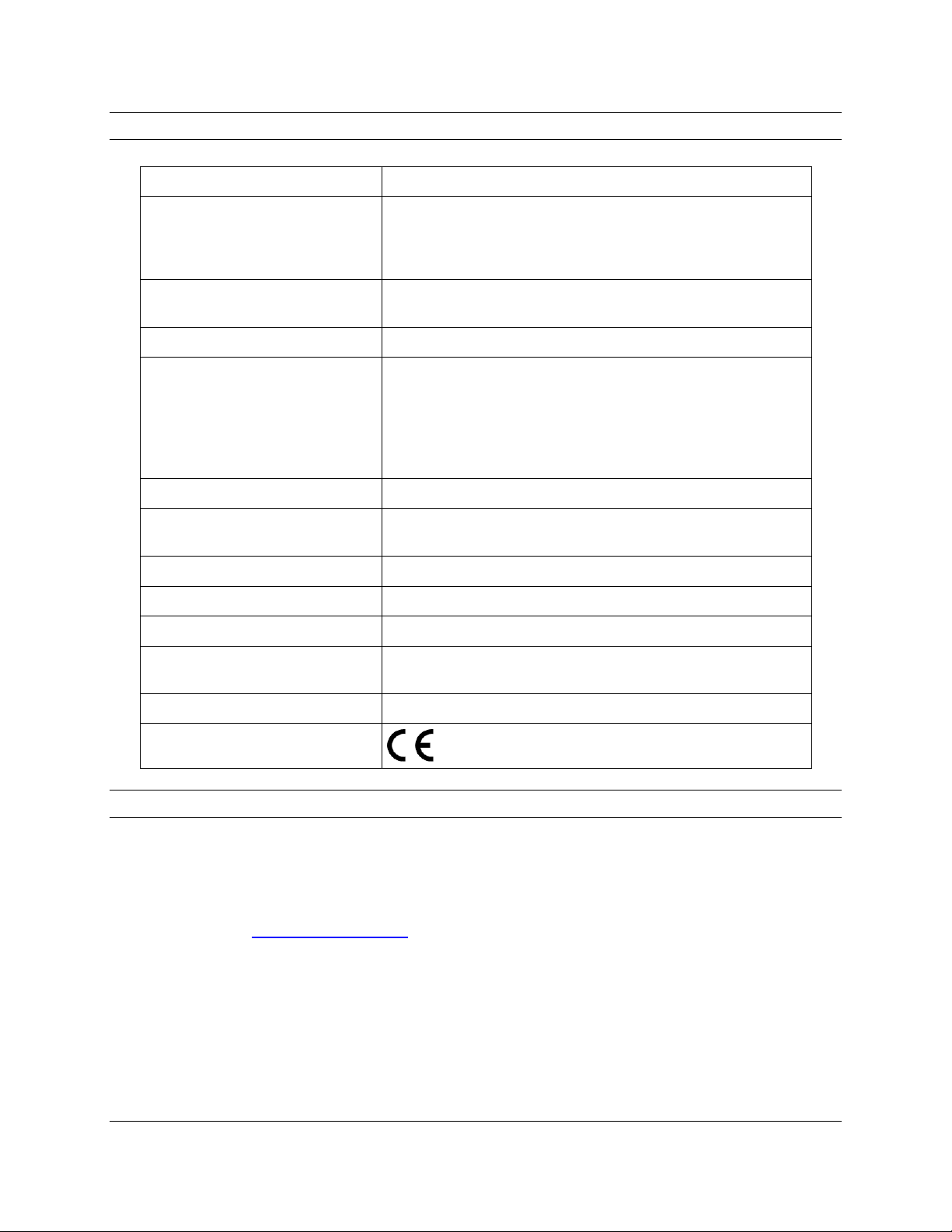
PARAMETER
SPECIFICATION
Size
Width: 254.0 mm (10.00 in)
Height: 152.5 mm (6.00 in)
Depth: 341.4 mm (13.44 in)
Weight: 3200 g (7.05 lbs)
Drop Parameters
Refill time and Dwell (0.1 msec resolution)
Number of drops (programmable from 1 to 1M)
Recipes
6 independent recipes, manual or remote triggers
Nozzle Heater
Heating to 70 C Max
± 1.0 C @ 50 C
PID control using platinum RTD, Auto tuning
24 VDC, 5.7 W, 100 Ω
Programmable shutoff timer
2 alarms for process control
First Drop Compensation
2 levels with programmable time interval
Interface
RS-232 Serial Port
LCD Display with Keypad
Input/Output
TTL level triggers
Operating Temperature
15 °C to 50 °C (59 °F to 122 °F)
Input Pressure
0.6 MPa (90 psi) - maximum
Input Power
100 – 240 VAC, 50/60 Hz, 115 W
Fuse: 5x20 mm, Fast-acting, 1.6 amp, 250 VAC
Advanjet Software
Windows XP, Vista, Windows 7 and Windows 8
Approvals
1.2 HV-2000C Controller Specifications
1.3 Technical Assistance
For technical assistance:
Phone: +1 760-294-3392
Web: www.advanjet.com
E-mail: info@advanjet.com
3A5856A Advanjet HV-2000C Jet Controller Setup and Operation Page 7 of 60

Note: Units are in millimeters [inches]
1.4 HV-2000C Controller Dimensions
Page 8 of 60 Advanjet HV-2000C Jet Controller Setup and Operation 3A5856A
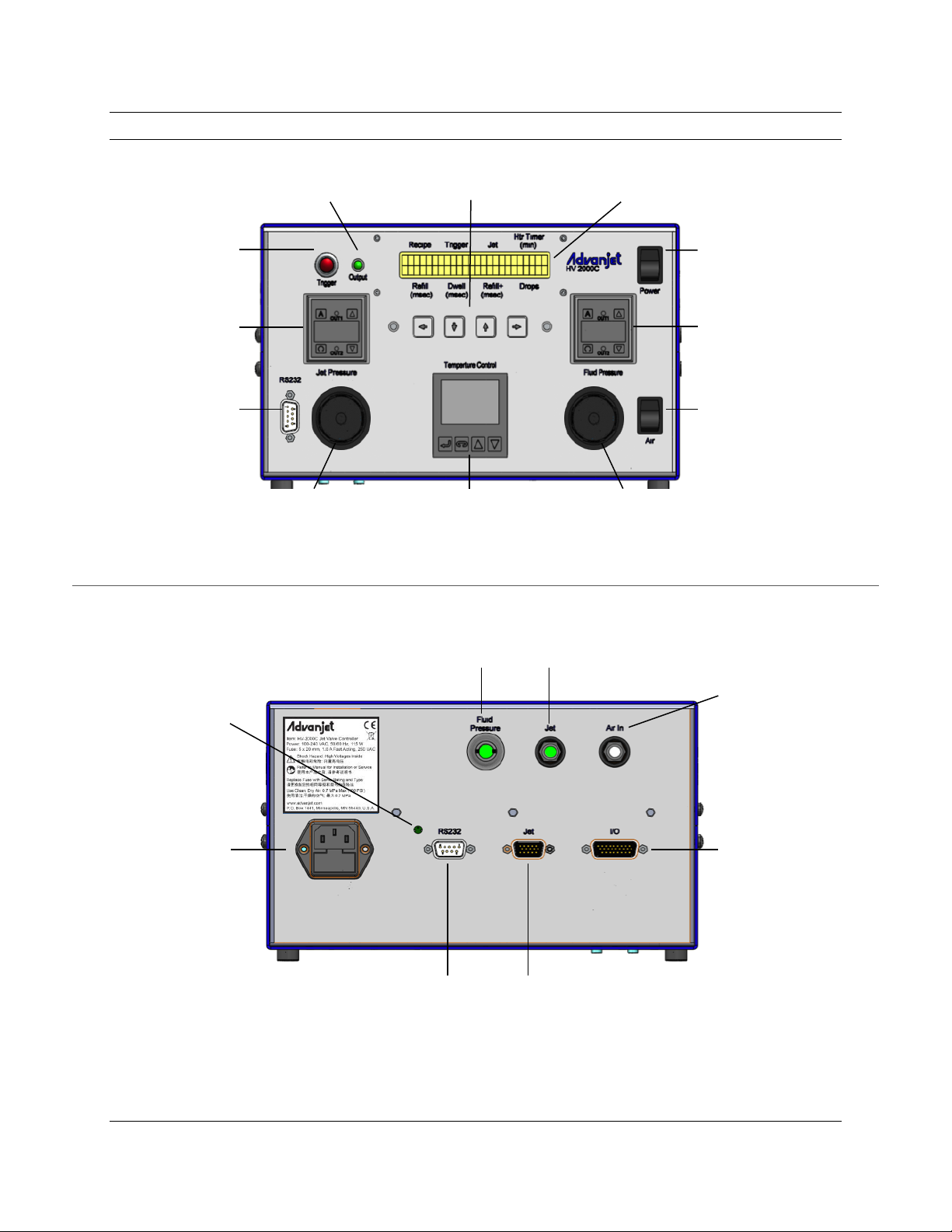
AC CONNECTOR
CORD.
LCD CONTRAST
SCREWDRIVER
JET PRESSURE OUTLET
CONNECT WITH A 6-MM Ø HOSE
FLUID PRESSURE OUTLET
PROVIDES FLUID DELIVERY AIR PRESSURE;
CONNECT TO THE FLUID SYRINGE WITH A 4-MM Ø HOSE
JET CONNECTOR
SYSTEM TO CONNECT WITH THE HV-2000 JET
RS-232 INTERFACE
CONNECTS THE HV-2000C TO A
PC RUNNING THE ADVANJET SOFTWARE WITH A
CONVERTER CABLE WITH CORRESPONDING DRIVER
AIR INLET
6-MM Ø HOSE
I/O CONNECTOR
CABLE
JET
ACTUATION PRESSURE
TRIGGER BUTTON
(ONCE)
RS-232 PORT
TO A PC VIA SERIAL
DB9-TO-USB CABLE
KEYPAD
CHANGES PARAMETER VALUES
LCD DISPLAY
PARAMETERS
TRIGGER LED
DISPENSING
TEMPERATURE
NOZZLE TEMPERATURE
JET PRESSURE
ACTUATION PRESSURE
FLUID PRESSURE
DELIVERY PRESSURE
POWER SWITCH
AIR SWITCH
DELIVERY PRESSURE
FLUID
DELIVERY PRESSURE
Figure 1-1: HV-2000C Front Panel
Figure 1-2: HV-2000C Rear Panel
1.5 HV-2000C Front and Rear Features
EXECUTES THE
DISPENSING RECIPE
ON LCD DISPLAY
PRESSURE GAUGE
DISPLAYS JET
CONNECTS HV-2000C
ILLUMINATES WHEN
CONTROLLER
REGULATES JET
MOVES LCD DISPLAY CURSOR,
CONTROLLER
REGULATES DISPENSING
SHOWS PROGRAM
TURNS THE
HV-2000C
MAIN POWER
ON/OFF
PRESSURE GAUGE
DISPLAYS FLUID
PROVIDES
QUICK ON/OFF
CONTROL OF FLUID
CONTROLLER
REGULATES FLUID
ADJUSTS THE
CONTRAST LEVEL
ON THE LCD
DISPLAY; ROTATE
THE SWITCH WITH
A SMALL
WITH FUSE
100 TO 240 VAC.
REQUIRED FUSE:
5X20 MM, FAST-
ACTING, 1 AMP,
250 VAC. OPERATE
IN OTHER
COUNTRIES USING
LOCAL POWER
SERIAL DB9-TO-USB CABLE OR A USB-TO-RS-232C
PROVIDES JET DISPENSER AIR PRESSURE;
CONNECTS TO
THE SOURCE
PRESSURE WITH A
TRIGGERS THE
DISPENSING
RECIPES AND
OUTPUTS, BUSY
FLAG, AND ERROR
SIGNALS FROM
THE HEATER
CONTROLLER AND
PRESSURE
GAUGES; USES A
STANDARD
5-FOOT 26-PIN
SENDS OUTPUT TRIGGER SIGNALS FOR THE DISPENSING
JET AND HEATER SETTINGS
**MUST USE THE ADVANJET CABLE SUPPLIED WITH THE
3A5856A Advanjet HV-2000C Jet Controller Setup and Operation Page 9 of 60

NOTICE
It is imperative that the air supplied to the HV-2000 is clean and dry
and free from debris and water. A 40-micron filter, a water separator,
and an overpressure relief valve set at around 120 psi (0.83 MPa)
are highly recommended. If the air is not clean and dry, serious
damage can occur to the solenoid valves. The air supply pressure
should be between 70 and 100 psi (0.48 and 0.70 MPa).
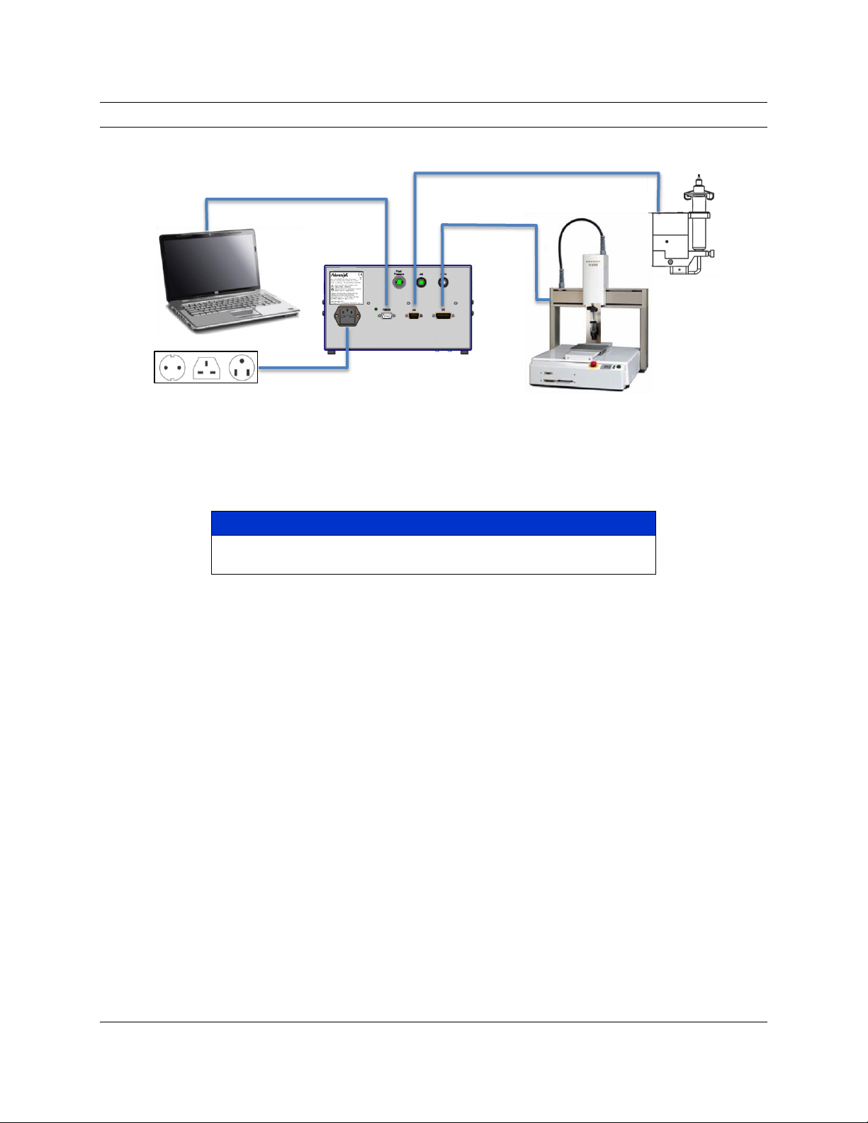
Figure 2-1: HV-2000C Pneumatic Connections
FLUID PRESSURE
4-MM OD TUBE [LOCKING BAYONET]
JET PRESSURE
6-MM OD TUBE [SLIP CONNECT COUPLER]
AIR IN
6-MM OD TUBE
2. Installation and Setup
2.1 Physical Placement
The HV-2000C controller should be placed in a location where the front panel controls
can be viewed and accessed. The ventilation holes on the sides should not be blocked.
2.2 Pneumatic System
Air In: Referring to Figure 2-1, connect an independently regulated and filtered main air
source to the rear of the HV-2000C controller. Use a 40-micron filter (at minimum). The
air must be clean and dry, and at a pressure of 70 to 100 psi (0.48 and 0.70 MPa).
Jet Pressure: The HV-2000 jet is supplied with a 6-mm OD air tube and terminates with
a slip connect coupler. Connect this tube to the JET connector on the rear of the
controller. Normal jet air operation is usually between 40 and 60 psi (0.28 and 0.41
MPa).
Fluid Pressure: Pressure to the dispensing fluid is supplied through a 4-mm OD tube
with a locking bayonet coupler. Connect this tube to the FLUID PRESSURE connector
on the rear of the controller.
Page 10 of 60 Advanjet HV-2000C Jet Controller Setup and Operation 3A5856A
NOTICE
To prevent unintended dispensing, be sure that all power is off when
connecting or disconnecting cables from the Advanjet controller.
JET CABLE
I/O CABLE
RS-232C CABLE
POWER CORD
Figure 2-2: HV-2000C Cable Connections
2.3 Electrical Interface
Four cable connections are on the rear of the Advanjet controller: Power cord, RS-232,
Jet, and Digital I/O, as shown in Figure 2-2. To assure proper connections to the
Advanjet controller, each of the standard cables supplied by Advanjet has a distinct
connector.
Power: The power cord set includes a standard 3-wire cable (hot, neutral, ground) with
an IEC C13 straight International female connector on one end and a country-specific
plug at the other end. Advanjet is prepared to supply cord sets for the USA, for the UK
(part no. 121057), and a standard Euro connector (part no. 121056).
RS-232: The Advanjet software requires an RS-232C communication interface with the
Advanjet controller. If your computer does not have an RS-232C port, use a USB to RS232C converter cable with the drivers that come with the cable. Advanjet can supply an
RS-232C-to-USB cable and corresponding driver.
Jet: The Jet cable is a high-density HD-15 cable and should be attached directly to the
HV-2000 Jet and the controller.
I/O (for HV-2000C): The robot’s controller uses the input/output cable to trigger the
HV-2000 to fire the sequence of drops programmed into the Advanjet controller. The I/O
cable should be connected directly to the host robot’s controls. A male DB-26 connector
is required to interface with the I/O cable. The Advanjet controller has an internal
nonvolatile memory that retains the jet parameters that were downloaded into the
controller. The controller provides 6 TTL trigger lines to control jet operations. See
Section 2.4 for more details.
3A5856A Advanjet HV-2000C Jet Controller Setup and Operation Page 11 of 60

I/O PIN ASSIGNMENTS
HD26
HV-2000C
1
Recipe 1 (Input)
2
Recipe 2 (Input)
3
Recipe 3 (Input)
4
Recipe 4 (Input)
5
Recipe 5 (Input)
6
Recipe 6 (Input)
7
Busy Flag (Output)
8
External Interrupt (Input)
9
GND
10
D/A Converter Output
11
Buffered A/D Converter Inputs
12
Buffered A/D Converter Inputs
13
D/A Converter Output
14
GND
15
No connection
16
No connection
17
No connection
18
Heater Alarm Common (Output)
19
Fluid Pressure Alarm Common 2
20
Fluid Pressure Alarm 2 (Output)
21
Fluid Pressure Alarm 1 (Output)
22
Jet Pressure Alarm Common 1
23
Jet Pressure Alarm 2 (Output)
24
Jet Pressure Alarm 1 (Output)
25
Heater Alarm 1 (Output)
26
Heater Alarm 2 (Output)
2.4 Input / Output Connections
A standard, 5-foot 26-pin Input/Output cable is supplied with the HV-2000C. The table
below describes the I/O connector pin assignments. The I/O is configured for the inputs
to be pulled down to GND. When the specific input is triggered, the Advanjet controller
will activate the corresponding preprogrammed Recipe # shown.
Pins 1 through 6 are outputs from the robot to the Advanjet controller.
They can be TTL outputs capable of sinking 2 mA of current,
or they can also be relay contacts.
Pin 7 outputs a busy status flag from the Advanjet controller to the robot.
Pin 8 is an external interrupt used to remotely stop a dispensing program.
Pins 9 and 14 are Isolated Ground.
Pins 18-26 are alarms from the heater and pressure sensors.
Note: Refer to Appendix 4 for I/O connection details.
Page 12 of 60 Advanjet HV-2000C Jet Controller Setup and Operation 3A5856A
JET
TRIGGER
BUTTON
RS-232
PORT
KEYPAD
LCD DISPLAY
TRIGGER LED
TEMPERATURE
CONTROLLER
JET PRESSURE
CONTROLLER
FLUID PRESSURE
CONTROLLER
POWER
SWITCH
AIR
SWITCH
FLUID
Figure 3-2:
Figure 3-3:
Figure 3-4:
3. Using the HV-2000C Controller Front Panel
PRESSURE
GAUGE
Figure 3-1: HV-2000C Front Panel
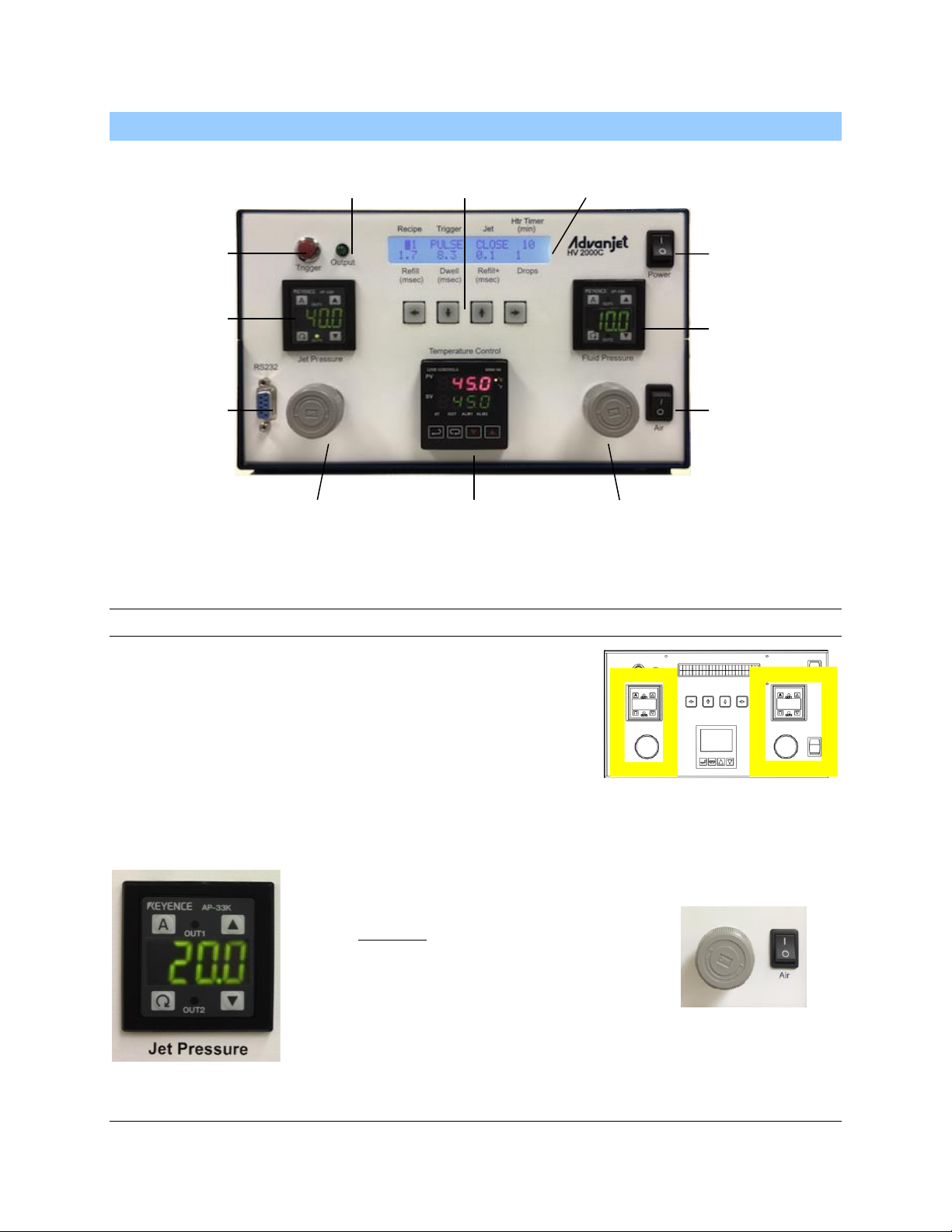
3.1 Jet and Fluid Pressure Regulators
The HV-2000C controller has two integrated air
regulators (see Figure 3-2) that control the pressure to
the Jet and the Fluid supply. Turn the knob clockwise to
increase and counterclockwise to decrease. Digital
gauges indicate the pressure levels; the Jet Pressure
gauge is pictured below. The default pressure unit on
the HV-2000C is psi (1 psi = 0.00689 MPa). Details
from the pressure regulator manufacturer are in
Appendix 3: Digital Pressure Gauge.
The Air Switch allows the operator
to instantly turn the Fluid Pressure
ON or OFF. This is very
convenient when changing fluid or
cleaning the jet.
PRESSURE
GAUGE
Pressure Regulators and
Air Swicth
Air Switch
Jet Pressure Gauge
3A5856A Advanjet HV-2000C Jet Controller Setup and Operation Page 13 of 60
PRESENT TEMPERATURE
SET POINT TEMPERATURE
―ENTER‖ KEY
―INDEX‖ KEY
Figure 3-6: Present Value (PV) , Set Value (SV),
Figure 3-7: Turn ON the Heater
Figure 3-5:
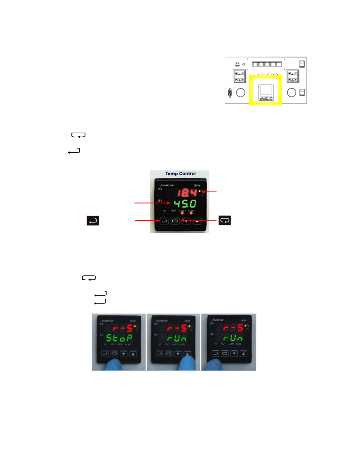
3.2 Temperature Controller
The HV-2000C Temperature Controller regulates the
temperature of the dispensing fluid and displays the
present and set point temperatures.
The main menu displays the present temperature
value (PV) in red on the top line of the display and the
set point temperature value (SV) in green on the
bottom line of the display.
Use the (INDEX) key to cycle through the menu options on the PV line,
the keys to scroll though settings or increase or decrease temperature values,
and the (ENTER) key to save an input and exit the menu.
Temperature Controller
ENTER Key and INDEX Key
To turn ON the heater:
Press until the Run-Stop Output Control screen (r-S) is on the PV line.
Use the keys to select the rUn setting to turn ON the heater.
Press the key to save the change. Now the heater is turned ON.
Press the key again to return to the main screen display.
Page 14 of 60 Advanjet HV-2000C Jet Controller Setup and Operation 3A5856A
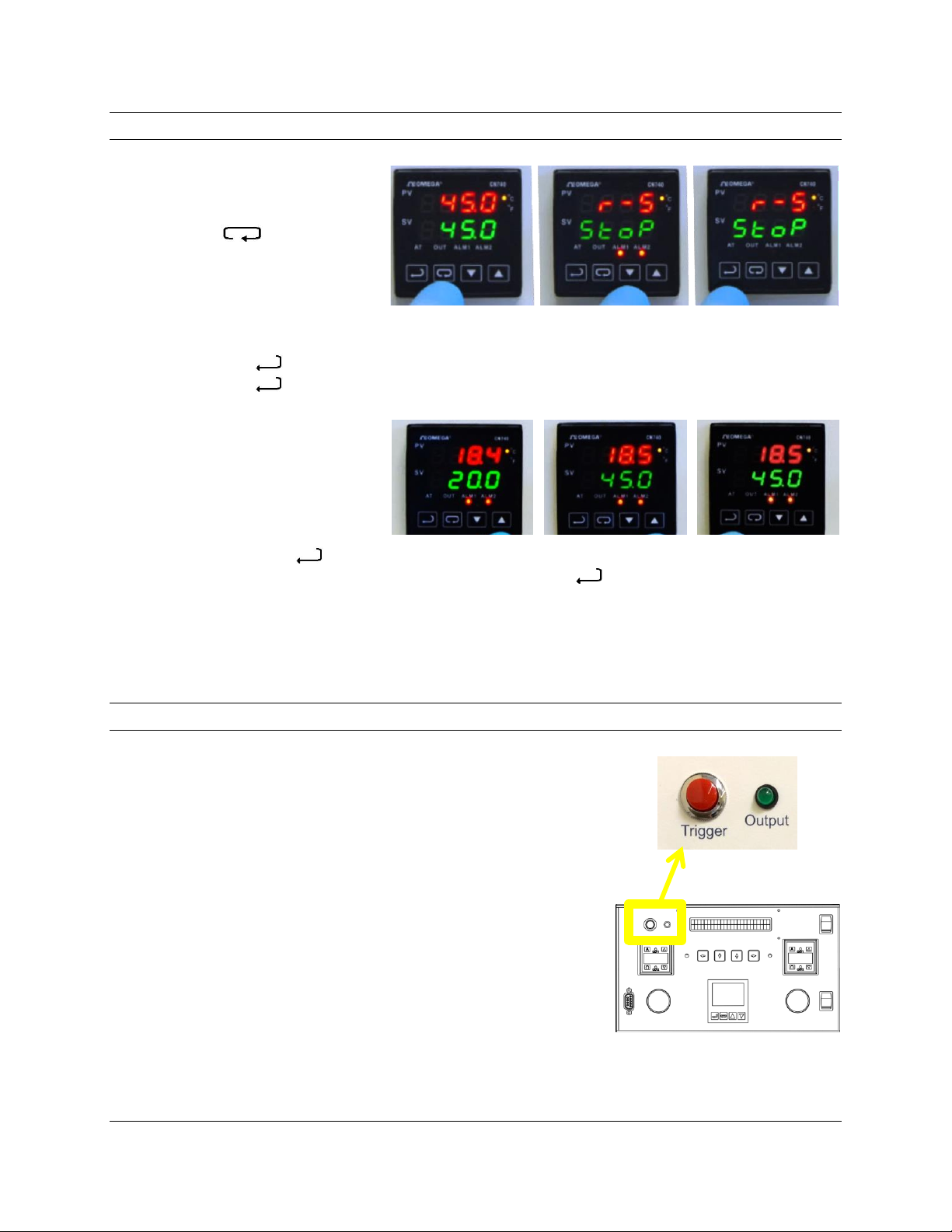
To turn OFF the heater:
Press until the
Run-Stop screen is
displayed (r-S).
Use the keys to
select the Stop setting
to turn OFF the heater.
Press the key to save the change. Now the heater is turned OFF.
Press the key again to return to the main screen display
To change the Set Value (SV)
temperature, use the keys
to increase/decrease the value.
For example, to change SV
from 20 to 45 degrees, use the
key to increase the SV value
to 45, and then press to
save the change.
Figure 3-8: Turn OFF the Heater
Figure 3-10:
Trigger Button and Output LED
3.2 Temperature Controller (Continued)
Figure 3-9: Press to increase the SV value to 45,
then press to save the change
Technical specifications of the heater can be found in Appendix 2: Temperature
Controller Factory Settings.
3.3 Trigger Button and LED
Pressing the Trigger Button immediately executes
the current recipe (recipe # and parameters)
displayed on the LCD screen. If multiple drops were
specified in the recipe, multiple drops will be
dispensed.
The Trigger Output LED is on when the Jet is firing
to verify a signal was sent to the Jet. The light is off
when the Jet is in idle state.
3A5856A Advanjet HV-2000C Jet Controller Setup and Operation Page 15 of 60
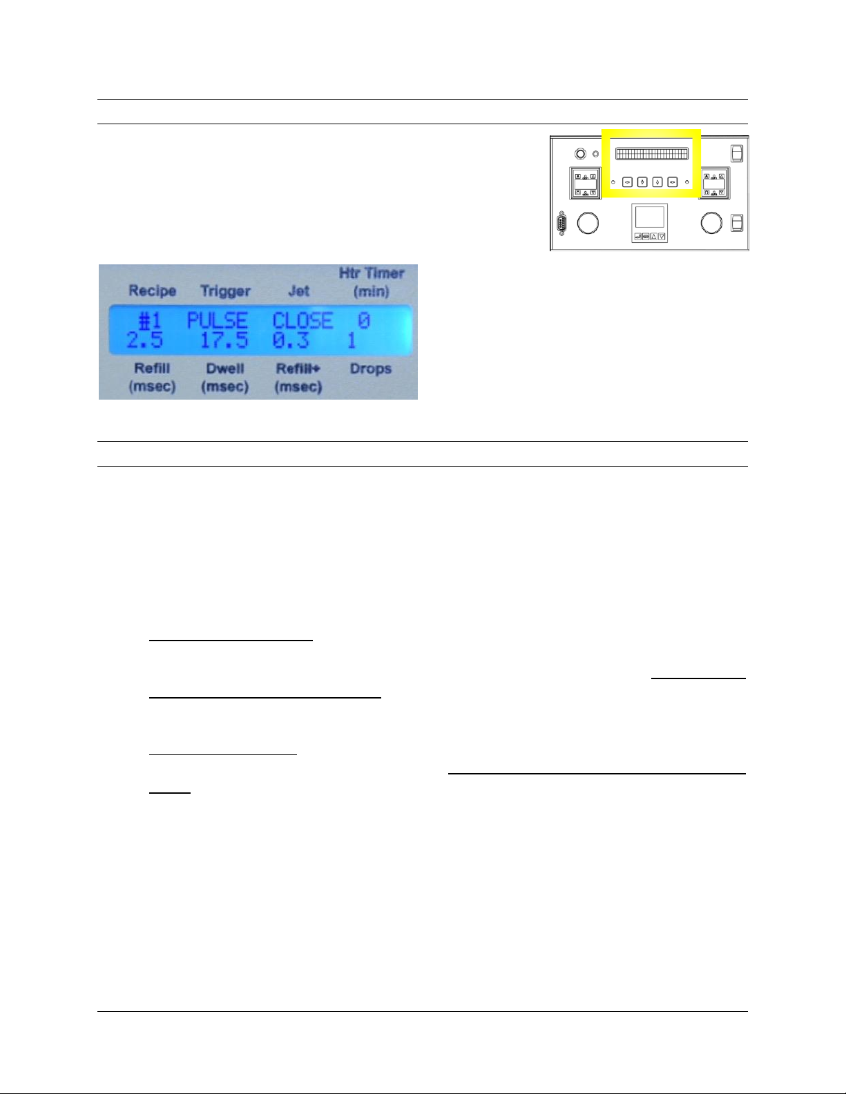
Figure 3-11:
LCD Display and Selection Keys
Figure 3-12: LCD Display with Cursor at Recipe #
3.4 LCD Display and Selection Keys
HV-2000C front panel programming and operation uses
the LCD display and input keypad, highlighted in Figure
3-11 at right. Eight basic settings can be input from the
main LCD menu. The selected setting is indicated by a
blinking cursor.
Figure 3-12 shows the cursor selecting the
Recipe #. Use the LEFT/RIGHT keys to
move the cursor and the UP/DOWN keys
to increment the values.
3.5 Jet Setting from the Front Panel
The eight jetting parameters on the LCD display can be programmed from the input
keypad.
Recipe: Select the recipe number from 1 to 6. Each recipe consists of the Trigger mode,
Refill time, Dwell time, Refill+ time (―first drop‖ adjustment), and the number of drops to
dispense. Up to 6 dispensing recipes can be programmed and saved in the controller.
Trigger: There are two Trigger modes—PULSE or LEVEL.
In the PULSE mode, the number of drops dispensed per trigger signal is
specified in the Drops setting. For example, if a recipe has set Trigger to PULSE
and Drops to 5, the jet will dispense 5 drops per Trigger signal. Pressing the
Trigger button in PULSE mode sends a Trigger signal and the jet will dispense 5
drops.
In the LEVEL mode, the jet will dispense drops nonstop until the Trigger signal
retreats—the Drops count is ignored. Pressing the Trigger button in LEVEL
mode causes LEVEL mode to be ignored, and the jet will dispense the number of
drops specified in the Drops.
Jet: Use this to CLOSE or OPEN the Jet valve.
Htr Timer (min): The Heater Off timer automatically turns off the heater after the Jet
has been idle for the specified number of minutes. This feature is useful if materials will
be adversely affected by long periods of heating. For example, some materials can be
―cured‖ by high temperature while sitting in the nozzle chamber for a long period of idle
time. If Htr Timer is set to zero, the Heater Off timer is not activated.
Page 16 of 60 Advanjet HV-2000C Jet Controller Setup and Operation 3A5856A
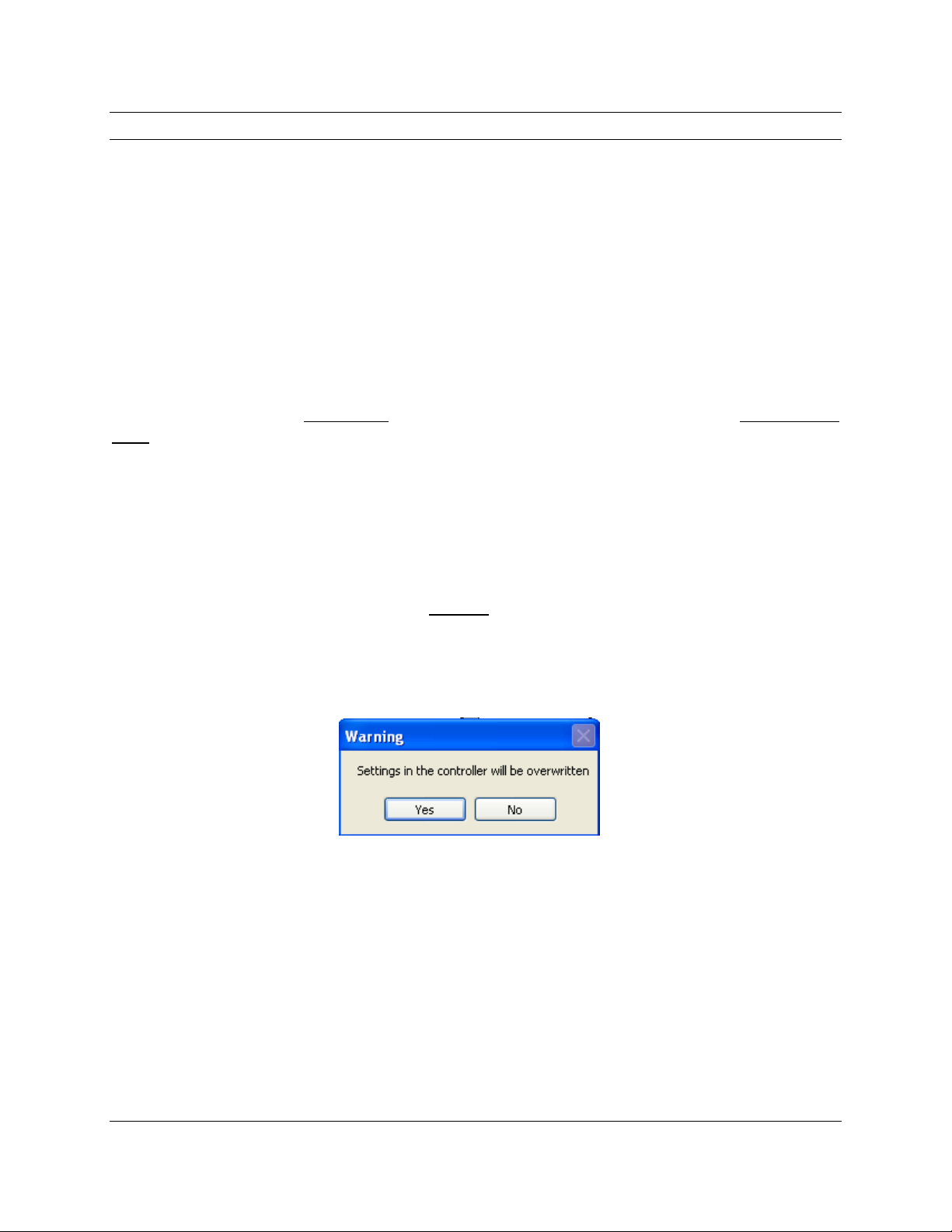
Figure 3-13: Overwrite Warning
3.5 Jet Setting from the Front Panel (Continued)
Refill (msec): Refill time is the time required for the material to flow into the nozzle after
each drop is ejected. Refill is set in msec with 0.1 msec resolution. Section 6.1 - Timing
Recipe Parameters provides a detailed explanation of Refill Time.
Dwell (msec): Dwell time is the time required for the material to flow out of the nozzle
and form a drop. Dwell is set in msec with 0.1 msec resolution. Section 6.1 - Timing
Recipe Parameters provides a detailed explanation of Dwell Time.
Refill+ (msec): Sometimes the jet requires a little extra time for the first drop to be
ejected, depending on the material or if the jet is idle for a period of time. Refill+ time is
added to Refill time to adjust the size and quality of the first drop. In PULSE mode,
Refill+ time applies to each drop; in LEVEL mode, Refill+ time applies to just the first
drop. Detailed explanations can be found in Section 6.2 – Programming Timing Recipes
(Adjust Refill Time for First Drop), and also Appendix 1: First Drop Compensation.
Drops: Specify the number of drops to be dispensed. To dispense a single drop per
trigger signal, enter 1. To dispense 10 drops per trigger signal, enter 10.
Note: If the Advanjet controller software is being used and values are changed using
the front panel display, the changes will not be transferred to the Advanjet controller
software. Also, the front panel values can be overwritten each time you start the
Advanjet software program. The warning below will be displayed. It is recommended to
write down any recipe changes made from the front panel and then enter them into the
software to synchronize.
3A5856A Advanjet HV-2000C Jet Controller Setup and Operation Page 17 of 60
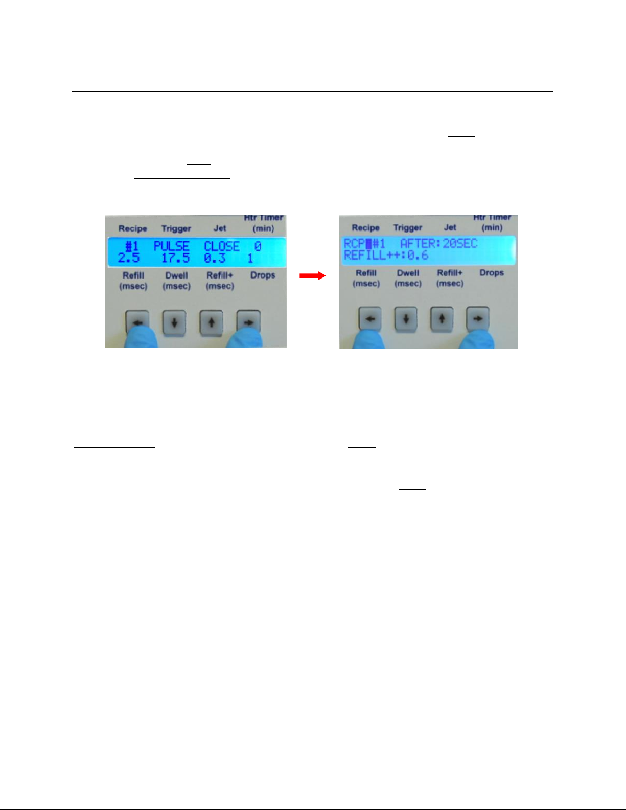
Figure 3-14: Press LEFT + RIGHT to Set the Refill++ Parameter
3.6 Special Front Panel Key Sequences
Pressing a combination of front panel keys accesses additional settings.
Refill++ time: Simultaneously pressing the LEFT and RIGHT keys once brings up the
Refill++ time menu. As another method of first drop compensation, Refill++ time is
added to Refill time after the jet is idled for a defined number of seconds. Refill++ time
applies to just the first drop in both PULSE and LEVEL modes. To access Refill++,
press LEFT + RIGHT once. The screen on the right appears:
For RCP, enter the recipe number. AFTER is the jet idle time in seconds, and
REFILL++ is the extra refill time. For a detailed explanation, see Section
6.2 - Programming Timing Recipes (Adjust Refill Time for First Drop), and also
Appendix 1: First Drop Compensation. After entering the REFILL++ settings,
simultaneously press the LEFT and RIGHT keys twice to accept the new settings and
return to the main menu.
RS-232 Settings: Simultaneously pressing LEFT+RIGHT twice brings up the RS-232
Settings menu. This setting is explained in detail in Section 4.2 - Changing the Default
RS-232 Settings. Press LEFT+RIGHT again to return to the main menu.
Page 18 of 60 Advanjet HV-2000C Jet Controller Setup and Operation 3A5856A
 Loading...