

Page 1
INSTRUCTIONS-PARTS LIST
308640
This manual contains important
warnings and information.
READ AND KEEP FOR REFERENCE.
INSTRUCTIONS
First choice when
quality counts.
t
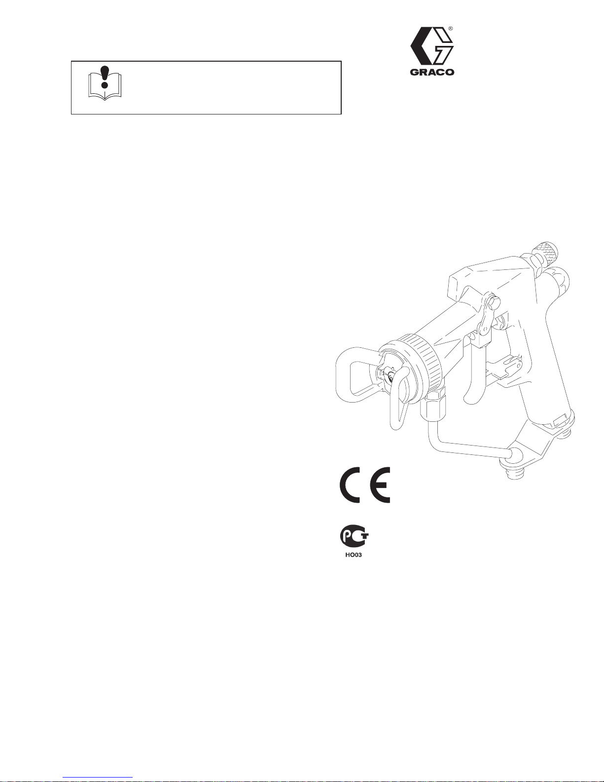
HIGH PRESSURE AIR-ASSISTED
Model AA Plust Spray Gun
4000 psi (28 MPa, 280 bar) Maximum Working Fluid Pressure
100 psi (0.7 MPa, 7 bar) Maximum Working Air Pressure
Part No. 238402, Series A
Spray Gun with standard spray tip, tip guard, air cap,
and 1/4–18 npsm (R1/4–19) air line fitting.
Part No. 238851, Series B
Spray Gun with AA Reverse-A-Cleanr (RAC) assembly and 1/4–18 npsm (R1/4–19) air line fitting.
Part No. 238852, Series A
Spray Gun with standard spray tip, tip guard, air cap,
and quick-disconnect air line fitting.
Rev. J
Supersedes G
includes Rev. H
Part No. 238883, Series A
Hi-Flow Spray Gun with Hi-Flow fluid needle and
diffuser-seat, and standard spray tip, tip guard, air cap,
and 1/4–18 npsm (R1/4–19) air line fitting.
Part No. 239001, Series B
Hi-Flow Spray Gun with Hi-Flow fluid needle and
diffuser-seat, AA Reverse-A-Clean (RAC) assembly,
and 1/4–18 npsm (R1/4–19) air line fitting.
Part No. 241070, Series A
HVLP Spray Gun with standard spray tip, HVLP air
cap, and 1/4–18 npsm (R1/4–19) air line fitting.
U.S. Patent Nos. 3,843,052; 4,386,739; 5,285,965
United Kingdom Patent No. 2 1 11 406 B
Patented 1984 Canada
Brevete 1984
French Patent No. 82–21202
Patents Pending
Foreign Patents Pending
05985
Part No. 238402 Spray Gun shown
GRACO INC. P.O. BOX 1441 MINNEAPOLIS, MN 55440–1441
ECOPYRIGHT 1996, GRACO INC.
Graco Inc. is registered to I.S. EN ISO 9001
Page 2
Table of Contents
Warnings 2. . . . . . . . . . . . . . . . . . . . . . . . . . . . . . . . . . . . . .
Installation 4. . . . . . . . . . . . . . . . . . . . . . . . . . . . . . . . . . . . .
Operation 7. . . . . . . . . . . . . . . . . . . . . . . . . . . . . . . . . . . . .
General Troubleshooting 14. . . . . . . . . . . . . . . . . . . . . . .
Spray Pattern Troubleshooting 15. . . . . . . . . . . . . . . . . .
Service 16. . . . . . . . . . . . . . . . . . . . . . . . . . . . . . . . . . . . . .
Parts 18. . . . . . . . . . . . . . . . . . . . . . . . . . . . . . . . . . . . . . . .
W ARNING
INJECTION HAZARD
Spray from the gun, hose leaks, or ruptured components can inject fluid into your body and cause an
extremely serious injury, including the need for amputation. Splashing fluid in the eyes or on the skin
can also cause a serious injury.
Fluid injected into the skin might look like just a cut, but it is a serious injury. Get immediate medi-
cal attention.
Do not point the spray gun at anyone or at any part of the body.
Do not put hand or fingers over the spray tip.
Do not stop or deflect fluid leaks with your hand, body, glove, or rag.
Spray Tip Selection Chart 22. . . . . . . . . . . . . . . . . . . . . .
Air Caps 22. . . . . . . . . . . . . . . . . . . . . . . . . . . . . . . . . . . . .
Dimensions 25. . . . . . . . . . . . . . . . . . . . . . . . . . . . . . . . . . .
Technical Data 26. . . . . . . . . . . . . . . . . . . . . . . . . . . . . . . .
Accessories 27. . . . . . . . . . . . . . . . . . . . . . . . . . . . . . . . . .
Warranty 28. . . . . . . . . . . . . . . . . . . . . . . . . . . . . . . . . . . . .
Graco Phone Number 28. . . . . . . . . . . . . . . . . . . . . . . . . .
Do not “blow back” fluid; this is not an air spray gun.
Always have the tip guard on the spray gun when spraying.
Check the gun diffuser operation weekly.
Be sure the gun trigger safety operates before spraying.
Lock the gun trigger safety when you stop spraying.
Follow the Pressure Relief Procedure on page 7 whenever you: are instructed to relieve pres-
sure; stop spraying; clean, check, or service the equipment; or install or clean the spray tip.
Tighten all the fluid connections before operating the equipment.
Check the hoses, tubes, and couplings daily. Replace worn, damaged, or loose parts immediately.
Permanently coupled hoses cannot be repaired; replace the entire hose.
TOXIC FLUID HAZARD
Hazardous fluids or toxic fumes can cause serious injury or death if splashed in the eyes or on the
skin, swallowed, or inhaled.
Know the specific hazards of the fluid you are using. Read the fluid manufacturer’s warnings.
Store hazardous fluid in an approved container. Dispose of hazardous fluid according to all local,
state and national guidelines.
Wear the appropriate protective clothing, gloves, eyewear and respirator.
RECOIL HAZARD
Due to the very high pressure fluid emitted, a strong recoil action will occur when you trigger this gun.
If you are unprepared, your hand could be forced back toward your body or you could lose your balance and fall, resulting in serious injury.
2 308640
Page 3
WARNING
EQUIPMENT MISUSE HAZARD
INSTRUCTIONS
Equipment misuse can cause the equipment to rupture, malfunction, or start unexpectedly and result
in serious injury.
This equipment is for professional use only.
Read all instruction manuals, tags, and labels before operating the equipment.
Use the equipment only for its intended purpose. If you are uncertain about usage, call your Graco
distributor.
Do not alter or modify this equipment. Use only genuine Graco parts and accessories.
Check the equipment daily. Repair or replace worn or damaged parts immediately.
Do not exceed the maximum working pressure of the lowest rated system component. This equip-
ment has a 4000 psi (28 MPa, 280 bar) maximum working pressure at 100 psi (0.7 MPa, 7 bar)
maximum incoming air pressure.
Route the hoses away from the traffic areas, sharp edges, moving parts, and hot surfaces. Do not
expose Graco hoses to temperatures above 180F (82C) or below –40F (–40C).
Do not use the hoses to pull the equipment.
Use only Graco approved hoses. Do not remove hose spring guards, which help protect the hose
from rupture caused by kinks or bends near the couplings.
Use fluids or solvents that are compatible with the equipment wetted parts. See the Technical
Data section of all the equipment manuals. Read the fluid and solvent manufacturer’s warnings.
Wear hearing protection when operating this equipment.
Comply with all applicable local, state and national fire, electrical and other safety regulations.
FIRE AND EXPLOSION HAZARD
Improper grounding, poor air ventilation, open flames, or sparks can cause a hazardous condition and
result in fire or explosion and serious injury.
Ground the equipment and the object being sprayed. See Ground the System on page 6.
Provide fresh air ventilation to avoid the buildup of flammable fumes from solvent or the fluid being
sprayed.
Extinguish all the open flames or pilot lights in the spray area.
Electrically disconnect all the equipment in the spray area.
Keep the spray area free of debris, including solvent, rags, and gasoline.
Do not turn on or off any light switch in the spray area while operating or if fumes are present.
Do not smoke in the spray area.
Do not operate a gasoline engine in the spray area.
If there is any static sparking while using the equipment, stop spraying immediately. Identify and
correct the problem.
308640 3
Page 4
Installation
C
L
A
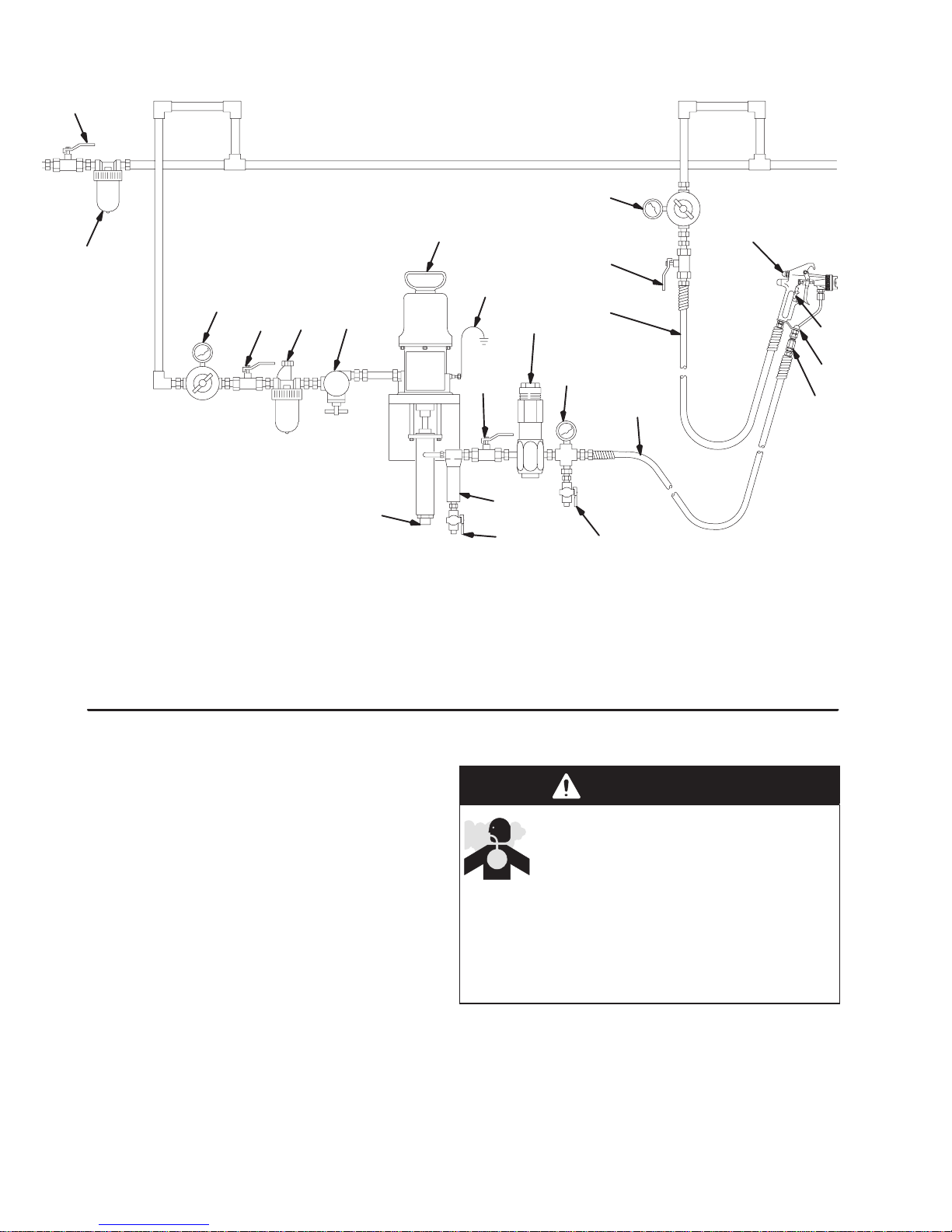
KEY
A Air Line Filter
B Air Line Lubricator
C* Bleed-type Air Shutoff Valve
D Pump Air Regulator
E* Fluid Drain Valve
F Fluid Shutoff Valve
G Fluid Filter
Fig. 1
D
CB
H* Grounded Fluid Hose
J Pump
K Air Line
L Air Pressure Regulator
M Pump Fluid Inlet
N In-line Fluid Filter
P Pattern Adjustment V alve Knob
Q* Fluid Pressure Regulator
J
P
X
V
T
Q
K
S
W
N
05986
M
F
R
H
G
E
E
R Pressure Gauge
S T rigger Safety
T Pump Runaway Valve
V* Pump Ground Wire
W Gun Fluid Connector
X Air Shutof f Valve
*Equipment required for safe operation of the
system. Must be purchased separately.
Typical Installation
The typical installation shown in Fig. 1 is only a guide
for selecting and installing air-assisted spray systems.
It is not an actual system design. Contact your Graco
distributor for assistance in designing a system to meet
your needs.
4 308640
Ventilate the Spray Booth
WARNING
TOXIC FLUID HAZARD
To prevent hazardous concentrations of
toxic and/or flammable vapors, spray
only in a properly ventilated spray booth.
Never operate the spray gun unless ventilation
fans are operating.
Check and follow all of the National, State and
Local codes regarding air exhaust velocity requirements.
Page 5
Installation
Connect the Air Line
1. Install an air line filter (A) to ensure a clean, dry air
supply to the gun. Dirt and moisture in the line can
ruin the appearance of your finished piece. See
Fig. 1.
2. Install an air pressure regulator (L) on the gun air
supply line to control the air pressure to the gun.
3. Install an air pressure regulator (D) on the pump
air supply line to control air pressure to the pump.
4. Install a bleed-type air shutoff valve (C) on the
main air line and on the pump air line, downstream
of the pump air regulator, to shut off air to the
pump. Install an additional bleed-type valve on
each pump air supply line to relieve air trapped
between this valve and the pump after the air
regulator is shut off.
WARNING
The bleed-type air shutoff valve is required in your
system to relieve air trapped between this valve
and the pump after the air regulator is closed.
Trapped air can cause the pump to cycle unexpectedly, which could result in serious injury.
NOTE:
Part No. 238402, 238851, 238883, 239001, and
241070 Guns:
(R1/4–19) compound male thread that is compatible with NPSM and BSP female swivel connectors.
Part No. 238852 Gun:
1/4–18 npsm quick-disconnect fitting.
The gun air inlet has a 1/4–18 npsm
The gun air inlet has a
Connect the Fluid Line
WARNING
INJECTION HAZARD
To reduce the risk of property damage or
serious injury, including fluid injection,
which could be caused by component
rupture or unrelieved fluid pressure,
A fluid drain valve(s) (E) is required in your
system to assist in relieving fluid pressure in the
displacement pump, hose and gun; triggering
the gun to relieve pressure may not be sufficient.
A fluid pressure regulator (Q) must be installed
in the system if the pump’s maximum working
pressure exceeds the gun’s maximum fluid
working pressure of 4000 psi (28 MPa, 280
bar).
1. Install a fluid filter (G) and drain valve(s) (E) close
to the pump’s fluid outlet. The drain valve assists
in relieving fluid pressure in the displacement
pump, hose, and gun. See Fig. 1.
2. Install a fluid pressure regulator (Q) to control fluid
pressure to the gun.
NOTE: Some applications require fine-tuned control of
fluid pressure. You can control fluid pressure more
accurately with a fluid pressure regulator than by
regulating the air pressure to the pump.
3. Install a fluid shutoff valve (F) to shut off the fluid
supply to the gun.
5. Install an air shutoff valve (X) on each gun air
supply line, downstream of the gun air regulator, to
shut off air to the gun(s).
6. Connect the air hose (K) from the air supply to the
gun air inlet.
4. Install an in-line fluid filter (N) on the gun fluid
fitting (W) to avoid clogging the spray tip with
particles from the fluid.
5. Connect the grounded fluid hose (H) to the gun
fluid fitting (W) or optional in-line filter (N).
308640 5
Page 6

Installation
Ground the System
WARNING
FIRE AND EXPLOSION HAZARD
Improper grounding could cause static
sparking, which could cause a fire or
explosion. To reduce the risk of property
damage or serious injury, follow the
grounding instructions below.
The following grounding instructions are minimum
requirements for a system. Your system may include
other equipment or objects which must be grounded.
Check your local electrical code for detailed grounding
instructions for your area and type of equipment. Your
system must be connected to a true earth ground.
1. Pump: Ground the pump by connecting a ground
wire and clamp between the fluid supply and a true
earth ground as instructed in your separate pump
instruction manual.
2. Air compressors and hydraulic power sup-
plies: Ground them according to the manufacturer
recommendations.
3. Air, fluid, and hydraulic hoses connected to
the pump: Use only electrically conductive hoses
with a maximum of 500 feet (150 m) combined
hose length to ensure grounding continuity. Check
the electrical resistance of your air and fluid hoses
at least once a week. If the resistance exceeds the
recommended limits, replace the hose immediately.
4. Spray gun: Ground the gun by connecting it to a
properly grounded fluid hose and pump.
5. Fluid supply container: Ground it according to
local code.
6. Object being sprayed: Ground it according to
local code.
7. All solvent pails used when flushing: Ground
them according to local code. Use only metal pails,
which are conductive. Do not place the pail on a
non-conductive surface, such as paper or cardboard, which interrupts the grounding continuity.
8. To maintain grounding continuity when flush-
ing or relieving pressure: Always hold a metal
part of the gun firmly to the side of a grounded
metal pail, then trigger the gun.
6 308640
Page 7
Operation
Safety
WARNING
INJECTION HAZARD
Remember, this is not an air spray gun.
For your safety be sure to read and
follow the Warnings on pages 2 and 3
and throughout the text of this instruction manual.
Keep the wallet sized warning card 179960, pro-
vided with the gun, with the operator of this equipment at all times. The card contains important
treatment information should an injection injury
occur. Additional cards are available at no charge
from Graco.
Pressure Relief Procedure
WARNING
INJECTION HAZARD
The system pressure must be manually
relieved to prevent the system from
starting or spraying accidentally. Fluid
under high pressure can be injected through the
skin and cause serious injury. To reduce the risk of
an injury from injection, splashing fluid, or moving
parts, follow the Pressure Relief Procedure
whenever you:
are instructed to relieve the pressure,
stop spraying,
check or service any of the system equipment,
or install or clean the spray tip.
5. Hold a metal part of the gun firmly to the side of a
grounded metal waste container and trigger the
gun to relieve the fluid pressure.
6. Lock the gun trigger safety again.
7. Open the pump drain valve (required in the system) to help relieve fluid pressure in the displacement pump. In addition, open the drain valve
connected to the fluid pressure gauge (in a system
with fluid regulation) to help relieve fluid pressure
in the hose and gun. Triggering the gun to relieve
pressure may not be sufficient. Have a container
ready to catch the drainage.
8. Leave the drain valve(s) open until you are ready
to spray again.
9. If you suspect that the spray tip or hose is completely clogged or that pressure has not been fully
relieved after following the steps above
slowly loosen the hose end coupling and relieve
pressure gradually, then loosen the coupling
completely. Now clear the tip or hose obstruction.
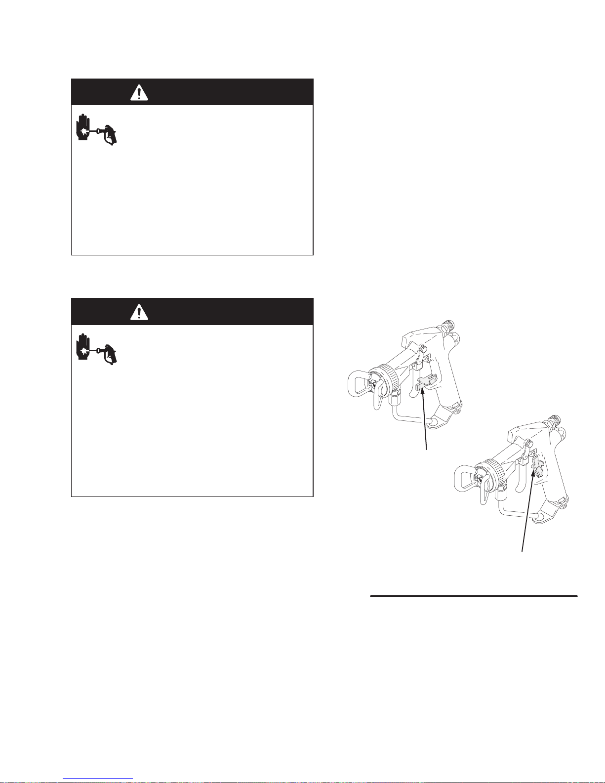
Trigger Safety
Locked or in
ON SAFE
Position
, v
ery
1. Lock the spray gun trigger safety to avoid accidentally triggering the gun. See Fig. 2.
2. Shut off the power to the pump.
3. Close the bleed-type master air valve (required in
the system).
4. Unlock the gun trigger safety.
Fig. 2
Trigger Safety Unlocked
or in
OFF SAFE
Position
308640 7
05987
Page 8
Operation
How the Air-Assisted Spray Gun Operates
The air-assisted spray gun combines airless and air
spraying concepts. The spray tip shapes the fluid into
a fan pattern, as does a conventional airless spray tip.
Air from the air cap further atomizes the fluid and
completes the atomization of the paint tails into the
pattern to produce a more uniform pattern. The width
of the pattern can be slightly adjusted by the pattern
adjustment valve.
Note that the air-assisted spray gun differs from an air
spray gun in that increasing the pattern air reduces the
pattern width. To increase the pattern width, less
pattern air or a larger size tip must be used.
The spray gun has a built-in lead and lag operation.
When triggered, the gun begins emitting air before the
fluid is discharged. When the trigger is released, the
fluid stops before the air flow stops. This helps assure
the spray is atomized and prevents fluid buildup on the
air cap.
Install a Spray Tip
WARNING
INJECTION HAZARD
To reduce the risk of a fluid injection
injury, follow the Pressure Relief Proce-
dure on page 7 before removing or
installing a spray tip.
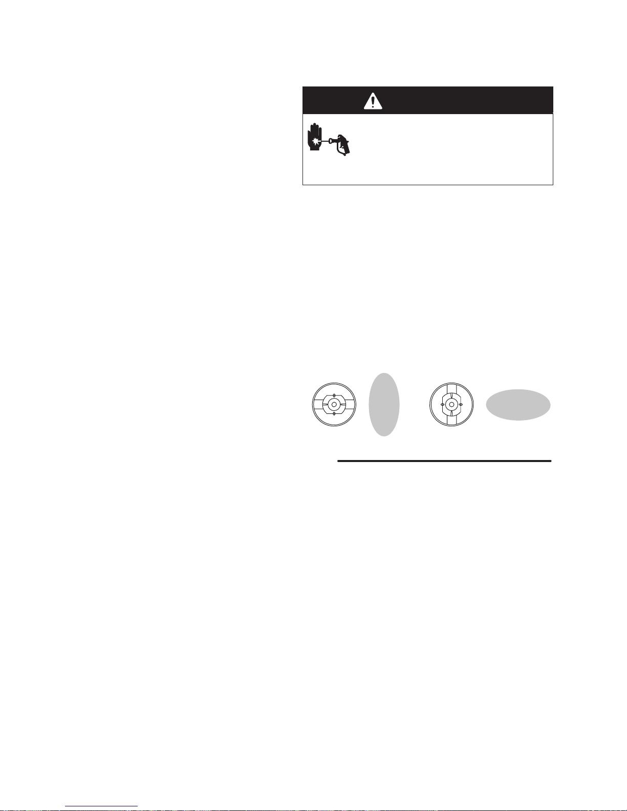
Install a spray tip in the gun. The air cap and spray tip
position determines the direction of the spray pattern.
Rotate the air cap (the spray tip rotates with it) as
needed for the desired spray pattern direction. See
Fig. 3.
NOTE: If the gun has the AA RAC assembly, handtighten the air cap retaining ring, while holding the
orange tip guard in the desired direction. If the retaining ring is over-tightened, the spray tip will be difficult
to rotate.
Vertical Spray Pattern Horizontal Spray Pattern
Select a Spray Tip and Air Cap
The fluid output and pattern width depend on the size
of the spray tip, the fluid viscosity, and the fluid pressure. Use the Spray Tip Selection Chart, on page 22,
as a guide for selecting an appropriate spray tip for
your application.
Fig. 3
05991
8 308640
Page 9
Operation
A
Adjust the Spray Pattern
WARNING
RECOIL HAZARD
Due to the very high pressure fluid
emitted, a strong recoil action will occur
when you trigger this gun. If you are
unprepared, your hand could be forced back
toward your body or you could lose your balance
and fall, resulting in serious injury.
WARNING
INJECTION HAZARD
To reduce the risk of component rupture
and serious injury, including injection, do
not exceed the gun’s maximum fluid
working pressure of 4000 psi (28 MPa, 280 bar) or
the maximum working pressure of the lowest rated
component in the system.
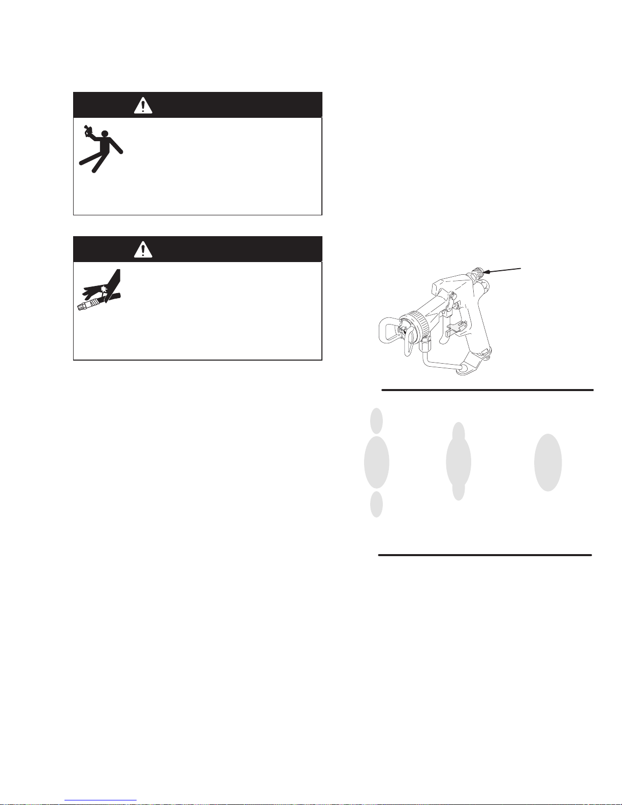
5. Set the atomizing air pressure at about 10 psi (0.7
bar, 70 kPa). Check the spray pattern, then adjust
the air pressure until the tails are completely
atomized and pulled into the spray pattern. See
Fig. 5. Do not exceed 100 psi (0.7 MPa, 7 bar) air
pressure to the gun.
For a narrower pattern,
valve knob clockwise. If the pattern is still not
narrow enough, increase the air pressure to the
gun slightly or use a different size tip.
NOTE: Pattern adjustment is not available with
guns with the AA RAC assembly as the air separator, part no. 178414, must be removed when the
RAC assembly is installed.
turn the pattern adjustment
Pattern
Adjustment
Knob
1. Set the fluid pressure with the fluid regulator. Do
not turn on the air supply yet.
2. Trigger the gun to check the atomization; do not be
concerned about the pattern shape yet.
3. Increase the fluid pressure just to the point where
a further increase in fluid pressure does not significantly improve fluid atomization.
4. Close the pattern adjustment valve by turning the
knob (see Fig. 4) counterclockwise all the way.
This sets the gun for its widest pattern.
Fig. 4
No Air T oo Little Air Right Amount
of Air
Fig. 5
0789
0792
308640 9
Page 10

Operation
Apply the Fluid
When applying the fluid, keep the gun a consistent
distance, about 8 to 12 inches (200 to 300 mm) from
the surface of the object being sprayed. Always hold
the gun at a right angle from the surface. Do not make
an arc with the gun as it causes an uneven coat of
fluid. See Fig. 6.
CAUTION
Openings in the tip guard reduce paint buildup on the
guard while spraying. Damage to the sharp edges of
the openings will cause paint to collect at that area.
To avoid damage, never hang the gun by the tip
guard.
RIGHT
Fig. 6
WRONG
0793A
10 308640
Page 11

Operation
Clean the Spray Gun and System Daily
WARNING
INJECTION HAZARD
To reduce the risk of an injection injury
or splashing fluid in the eyes or on the
skin:
Follow the Pressure Relief Procedure on page
7 before cleaning, removing, or installing a
spray tip and whenever you are instructed to
relieve pressure.
Do not wipe fluid buildup off the gun or spray tip
until pressure is relieved.
CAUTION
To avoid damaging the gun:
Never immerse the gun in solvent as this could
damage packings and allow solvent in the air
passages.
Do not use fluids containing halogenated
hydrocarbons to clean the gun body as HHC is
not compatible with aluminum.
Methylene Chloride is not recommended as a
flushing or cleaning solvent with this gun or any
device with nylon or aluminum components.
Do not use metal tools to clean holes in the air
cap or spray tip.
4. If using an in-line filter, remove and clean it
thoroughly in a compatible solvent.
5. Clean the system’s fluid filter and air line filter.
Check the Diffuser-seat Operation Weekly
WARNING
INJECTION HAZARD
The gun diffuser-seat breaks up spray
when the gun is sprayed without the
spray tip installed, such as during flushing. This reduces the risk of an injection injury.
Check the diffuser-seat operation weekly.
1. Relieve the pressure as instructed on page 7.
2. Remove the tip guard and spray tip.
3. Start the pump and operate it at its lowest pressure.
4. Hold a metal part of the gun firmly against a
grounded metal waste container, and trigger the
gun. See Fig. 7. If the fluid coming from the gun is
not diffused into an irregular stream, replace the
diffuser-seat immediately.
1
NOTE: Clean the front of the tip frequently during the
day to help reduce buildup. AA RAC style tips require
more frequent cleaning.
1. Relieve the pressure as instructed on page 7.
2. Clean the outside of the gun and the tip guard with
a soft cloth dampened with compatible solvent.
3. To avoid damaging the spray tip and air cap, clean
them with a compatible solvent and soft brush. To
clean the air cap passages, use a soft brush or
other soft tool. Dry the parts with an air blow gun.
1
Maintain firm metal-to-metal contact between the gun and a
grounded metal container.
Fig. 7
05988
308640 11
Page 12

Operation
Flush the Gun Daily
WARNING
INJECTION HAZARD
To reduce the risk of a fluid injection
injury, follow the Pressure Relief Proce-
dure on page 7 before cleaning,
removing, or installing a spray tip and whenever
you are instructed to relieve pressure.
WARNING
To reduce the risk of serious injury, including
splashing fluid in the eyes or on the skin, or static
electric discharge when flushing:
Be sure the entire system, including flushing
pails, are properly grounded.
Remove the tip guard and spray tip.
Maintain metal-to-metal contact between the
gun and a grounded metal waste container. See
Fig. 7, page 11.
Use the lowest possible pressure.
1. Relieve the pressure as instructed on page 7.
2. Disconnect the atomizing air hose and the fluid
supply line.
3. Remove the tip guard or AA RAC assembly (11),
air cap or RAC housing (13), and spray tip (14).
Refer to the parts drawing for your gun model
(page 18 or 20).
4. Clean the parts.
5. Connect a compatible solvent supply to the gun.
6. Start the pump and operate it at its lowest pressure.
7. Hold a metal part of the gun firmly against a
grounded metal waste container, and trigger the
gun until all the paint is removed from the gun
passages.
8. Relieve the pressure as instructed on page 7.
9. Disconnect the solvent supply.
NOTE:
Flush the pump and gun before the fluid can dry in
it.
If it is available, the flushing procedure provided in
the pump or sprayer manual should be used
instead of this procedure.
NOTE:
materials,
clean it with a soft brush to ensure that the material
does not cure in the spring area and make the gun
inoperable. See page 16 to remove the needle cartridge.
If the gun is being used with plural component
remove the needle cartridge and thoroughly
12 308640
Page 13

Notes
308640 13
Page 14

Troubleshooting
g
NOTE:
WARNING
INJECTION HAZARD
To reduce the risk of a fluid injection
injury, follow the Pressure Relief Proce-
dure on page 7 before checking or
servicing any of the system equipment and whenever you are instructed to relieve pressure.
General Troubleshooting
Problem Cause Solution
Fluid leakage from back of fluid
needle
Air leakage from front of gun Air valve not seating properly Clean/service air valve. See page 16.
Fluid leakage from front of gun
Fluid in air passages
Slow fluid shut-off Fluid buildup on fluid needle cartridge
Worn packings or needle shaft Replace external needle packings or
Fluid needle worn or damaged Replace fluid needle cartridge. See
Worn diffuser-seat housing Replace the diffuser-seat and gasket.
Fluid tip seal leaking Tighten or replace fluid tip.
Leaking around diffuser-seat housing Replace the diffuser-seat gasket. The
Fluid inlet fitting leaking Replace the fluid fitting gasket. The
components.
Check all possible remedies in the troubleshooting
charts before disassembling the gun.
Some improper patterns are caused by the
improper balance between air and fluid.
entire fluid needle cartridge. See
page 16.
page 16.
The gasket must be replaced whenever the diffuser-seat is removed.
See page 16.
gasket must be replaced whenever
the diffuser-seat is removed. See
page 16.
gasket must be replaced whenever
the fluid fitting is removed. See
page 17.
Remove and clean or replace the
fluid needle cartridge. See page 16.
Diffuser-seat is overtightened.
14 308640
Remove diffuser-seat and replace
diffuser-seat gasket. Torque diffuserseat to 90–100 in-lb (10.2–11.2
Nm).
Page 15

Troubleshooting
Spray Pattern Troubleshooting
Problem Cause Solution
Fluttering or spitting spray Insufficient fluid supply
Adjust fluid regulator or fill fluid supply
tank.
Air in paint supply line
Attempting to “feather” (partially trigger) the gun.
Irregular pattern Fluid build-up or spray tip partially
plugged
On defective side of pattern, air horn
holes are partially or totally plugged
Pattern pushed to one side, same
side of air cap gets dirty
Air horn holes partially or totally
plugged
Check, tighten siphon hose connections, bleed air from paint line.
Cannot “feather” with an AA gun.
Feathering will cause drastic reduction of pressure at the tip, resulting in
poor atomization and/or spitting.
Clean spray tip. See page 11.
Clean air horn holes with solvent and
soft brush. See page 11.
Clean air horn holes with solvent and
soft brush. See page 11.
308640 15
Page 16

Service
WARNING
INJECTION HAZARD
To reduce the risk of a fluid injection
injury, follow the Pressure Relief Proce-
dure on page 7 before checking or
servicing any of the system equipment and whenever you are instructed to relieve pressure.
NOTE:
Follow the Service Notes in Fig. 8 when reassem-
bling the gun. Refer to the parts drawing for your
gun model (page 18 or 20) for parts not shown in
Fig. 8.
Fluid Needle Cartridge Service
Follow the procedure below to remove the fluid needle
cartridge for cleaning or for replacement.
1. Relieve the pressure as instructed on page 7.
2. Remove the tip guard or AA RAC assembly (11),
air cap or RAC housing (13), spray tip (14), and air
separator (16 –
and 241070 guns only
3. Trigger the gun to back the fluid needle ball off the
seat. Remove the diffuser-seat (15).
4. Remove the trigger (3) and trigger extension
pieces (19). See the Parts Drawing, page 18.
part no. 238402, 238852, 238883,
). See Fig. 8.
Repair Kits are available. See page 19 or 21 for the
kits for your gun model.
Air Valve Service
1. Relieve the pressure as instructed on page 7.
2. Remove the trigger (3) and valve cap (7). See the
parts drawing and Fig. 8.
3. Unscrew the needle nut (23) while holding the flats
(C) of the air valve (26) stem with a long nose
pliers.
CAUTION
To avoid leakage, be careful not to scratch the air
valve stem.
4. Remove the spring (6) and air valve (26).
5. If there is air leakage at the air valve (26), unscrew
the packing nut (24) and carefully remove the
u-cup packing (25). Replace packing if worn or
damaged. When re-installing, be sure the u-cup
faces inward.
6. If leakage occurs internally or the front of the gun
leaks air when it’s not triggered, clean and inspect
the air valve and the spring for wear or damage.
Replace as needed.
7. For best air valve life, lubricate the external air
valve stem (C) with light oil after each day’s use.
5. To remove the fluid needle cartridge (10), slide the
notch of the packing tool (34) around the small
diameter of the trigger guide (A) and pull the
cartridge toward the front of the gun.
6. Remove the fluid gasket (18).
7. If the fluid needle cartridge was removed for
cleaning, remove the external o-ring (10a) and
backup ring (10b). Clean the needle cartridge
thoroughly with a compatible solvent and a soft
brush. Install a new o-ring (10a) and backup ring
(10b).
8. Lubricate the o-ring (10a) and backup ring (10b) of
the new or cleaned needle cartridge with lightweight oil.
9. Insert the fluid needle cartridge into the front end
of the gun body. Use the packing tool (34) to pull
back on the cartridge until it snaps into place; the
cartridge must be bottomed out in the gun body
insert. If the cartridge is seated properly, the
needle cartridge washer (B) will be visibly seated
flat through the back end of the gun body insert.
10. Insert a new gasket (18).
11. Install the gun trigger and trigger extension pieces.
12. Lubricate the diffuser-seat (15) thread. Trigger the
gun while screwing the diffuser-seat back into the
gun. Torque the diffuser-seat to 90 to 100 in-lb
(10.2 to 11.2 Nm).
13. Install the gun air separator
238852, 238883, and 241070 guns only)
air cap or RAC housing, and tip guard or AA RAC
assembly.
(part no. 238402,
, spray tip,
16 308640
Page 17

Part No. 238402 Spray Gun shown
1414
11
16
13
12
14
Service
5
4
11
12
5a
7
10
24
C
6
23
A
B
12
10b
10a
12
25
26
411
7
6
8
410
13
1
3 15
15
SERVICE NOTES:
Gasket (18) must be replaced if diffuser-seat (15) is removed
1
or replaced to avoid fluid leakage
Gasket (17) must be replaced if fluid connector (30) is removed
2
or replaced to avoid fluid leakage
Lubricate threads
3
Apply anaerobic pipe sealant to threads
4
Apply high strength sealant to threads
5
Thread nut to bottom thread of needle
6
Use tool (34) to pull needle cartridge until it bottoms in gun
7
body front end insert.
U-cup lips face inward
8
T orque to 23–27 ft-lb (31–37 Nm)
9
18
2
17
5 9
30
FLUID
T orque to 20–24 ft-lb (27–32 Nm)
10
T orque to 15–19 ft-lb (20–26 Nm)
11
Lubricate with light-weight oil
12
Do not lubricate
13
If the gun has the AA RAC assembly, tighten the air cap
14
retaining ring until it bottoms out, while holding the orange tip
guard in the desired direction.
T orque to 90–100 in-lb (10.2–1 1.2 Nm).
15
AIR
2
Fig. 8
05989
308640 17
Page 18

Parts
Part No. 238402, 238852, 238883, and 241070
12
14
13
11
5
5a
16
23
10
3
15
24
10a
18
25
4
10b
17
30
1
8
7
6
26
19
9
34
5b
29
SERVICE NOTES (See Fig. 8 for additional information):
1
Apply high strength sealant to threads.
T orque to 23–27 ft-lb (31–37 Nm)
2
Gasket (18) must be replaced if diffuser-seat (15) is removed or
3
replaced to avoid fluid leakage.
18 308640
3
12
6
2
5
2
05990A
Gasket (17) must be replaced if fluid connector (30) is removed or
4
replaced to avoid fluid leakage.
5
Included with Gun 238402, 238883, and 241070 only.
Included with Gun 238852 only.
6
Page 19

Parts
Use Only Genuine Graco Parts and Accessories
Part No. 238402, 238852, 238883, and 241070
Ref.
No. Part No. Description Qty.
1 238750 BODY, gun 1
2 106917 ADAPTER, air;
238402, 238883, and 241070 only
Included with Gun
113367 COUPLING, air, quick-disconnect;
Included with Gun 238852 only 1
3 276429 TRIGGER, gun 1
5 217489 VALVE, pattern adjustment;
Includes items 5a and 5b 1
5a 168110 S O-RING, nitrile rubber 1
5b 105456 S RETAINER, clip 1
6 106903 SPRING, compression, air valve 1
7 178408 CAP, valve, air 1
8 203953 CAP SCREW, hex hd, 10-24 x
0.375” long 1
9 187562 PIN, pivot 1
10 238754 NEEDLE, fluid;
238402, 238852, and 241070 only;
Includes replaceable items 10a, 10b
Included with Gun
238755 NEEDLE, fluid, hi-flow; Included
with Gun 238883 only; Includes
replaceable items 10a and 10b
10a 111516 S O-RING; CV75 1
10b 111517 S RING, backup; PTFE r 1
11 238248 TIP GUARD 1
12 107079 O-RING, PTFE 1
13 239781 AIR CAP;
238402, 238852, and 238883 only
239898 AIR CAP;
241070 only
Included with Gun
Included with Gun
14 GG4XXX SPRAY TIP; Customer’s choice;
See Chart on page 22.
replacement gasket 183616
Includes
15 238427 DIFFUSER-SEAT; Included with Gun
238402, 238852, and 241070 only
224855 DIFFUSER-SEAT, hi-flow; Included
with Gun 238883 only
16 178414 SEPARATOR, air 1
17 178422 GASKET, fluid, Delrinr;
1 sent unassembled 2
18 187521 GASKET, fluid; acetal homopolymer
(black), 1 sent unassembled 2
19 224868 TRIGGER EXTENSION 2
23 187504 NUT, needle 1
24 178765 NUT, packing, air 1
25 105452 U-CUP, PTFE 1
26 217487 VALVE, air 1
29 238228 GUARD, trigger 1
30 191026 CONNECTOR, fluid 1
31Y 222385 WARNING CARD (not shown) 1
34 187737 TOOL, needle assembly 1
Ref.
No. Part No. Description Qty.
35Y 172479 TAG, instruction (not shown) 1
Y
1
Replacement Warning labels, tags and cards are
available at no cost.
Repair Kits
Kit No. and
Dii
Description
224949
Gun Repair
Kit
1
1
235304
Fluid Section
Repair Kit
1
1
238739*
Hi-flow Gun
Repair Kit
1
1
1
238738*
Hi-flow Fluid
Section
Repair Kit
* Must be used with tips larger than 0.025 in. (0.635 mm).
Includes:
Ref. No. Part No. Description
5a
5b
6
10
10a
10b
12
15
17
18
25
26
10
10a
10b
15
17
18
5a
5b
6
10
10a
10b
12
15
17
18
25
26
10
10a
10b
15
17
18
168110
105456
106903
238754
111516
111517
107079
238427
178422
187521
105452
217487
238754
1 1 1516
1 1 1517
238427
178422
187521
168110
105456
106903
238755
111516
111517
107079
224855
178422
187521
105452
217487
238755
1 1 1516
1 1 1517
224855
178422
187521
O-Ring
Retainer
Spring
Needle
O-Ring
Backup Ring
O-Ring
Diffuser-seat
Gasket
Gasket
U-Cup
Valve
Needle
O-Ring
Backup Ring
Diffuser-seat
Gasket
Gasket
O-Ring
Retainer
Spring
Needle
O-Ring
Backup Ring
O-Ring
Diffuser-seat
Gasket
Gasket
U-Cup
Valve
Needle
O-Ring
Backup Ring
Diffuser-seat
Gasket
Gasket
308640 19
Page 20

Part No. 238851 and 239001
14a
13
Parts
11
5
5a
14
1
8
5b
7
6
25
26
24
23
10
10b
10a
19
18
15
3
17
4
30
9
29
12
SERVICE NOTES (See Fig. 8 for additional information):
1
Apply high strength sealant to threads.
T orque to 23–27 ft-lb (31–37 Nm)
2
3
Gasket (18) must be replaced if diffuser-seat (15) is removed or replaced to avoid fluid leakage.
4
Gasket (17) must be replaced if fluid connector (30) is removed or replaced to avoid fluid leakage.
20 308640
3
2
34
06759B
Page 21

Parts
Use Only Genuine Graco Parts and Accessories
Part No. 238851 and 239001
Ref.
No. Part No. Description Qty.
1 238750 BODY, gun 1
2 106917 ADAPTER, air 1
3 276429 TRIGGER, gun 1
5 217489 VALVE, pattern adjustment;
Includes items 5a and 5b 1
5a 168110 S O-RING, nitrile rubber 1
5b 105456 S RETAINER, clip 1
6 106903 SPRING, compression, air valve 1
7 178408 CAP, valve, air 1
8 203953 CAP SCREW, hex hd, 10-24 x
0.375” long 1
9 187562 PIN, pivot 1
10 238754 NEEDLE, fluid; Included with Gun
238851 only; Includes replaceable
items 10a and 10b
238755 NEEDLE, fluid, hi-flow;
Gun 239001 only; Includes
replaceable items 10a and 10b
Included with
10a 111516 S O-RING; CV75 1
10b 111517 S RING, backup; PTFE r 1
11 238701 AA RAC TIP GUARD/
AIR CAP ASSY. 1
13 192096 RAC HOUSING 1
14 242XXX AA RAC SPRAY TIP; Customer’s
choice. See Chart on page 24.
Includes item 14a. 1
14a 193000 S FLUID SEAT 1
15 239172 DIFFUSER-SEAT; Included with Gun
238851 only
239173 DIFFUSER-SEAT, hi-flow; Included
with Gun 239001 only
17 178422 GASKET, fluid, Delrinr;
1 sent unassembled 2
18 187521 GASKET, fluid; acetal homopolymer
(black),
1 sent unassembled 2
19 224868 TRIGGER EXTENSION 2
23 187504 NUT, needle 1
24 178765 NUT, packing, air 1
25 105452 U-CUP, PTFE 1
26 217487 VALVE, air 1
29 238228 GUARD, trigger 1
30 191026 CONNECTOR, fluid 1
31Y 222385 WARNING CARD (not shown) 1
34 187737 TOOL, needle assembly 1
35Y 172479 TAG, instruction (not shown) 1
1
1
1
1
Repair Kits
Kit No. and
Dii
Description
239176
Gun Repair
Kit
239178
Fluid Section
Repair Kit
239177*
Hi-flow Gun
Repair Kit
239179*
Hi-flow Fluid
Section
Repair Kit
* Must be used with tips larger than 0.025 in. (0.635 mm).
Includes:
Ref. No. Part No. Description
5a
5b
6
10
10a
10b
15
17
18
25
26
10
10a
10b
15
17
18
5a
5b
6
10
10a
10b
15
17
18
25
26
10
10a
10b
15
17
18
168110
105456
106903
238754
111516
111517
239172
178422
187521
105452
217487
238754
1 1 1516
1 1 1517
239172
178422
187521
168110
105456
106903
238755
111516
111517
239173
178422
187521
105452
217487
238755
1 1 1516
1 1 1517
239173
178422
187521
O-Ring
Retainer
Spring
Needle
O-Ring
Backup Ring
Diffuser-seat
Gasket
Gasket
U-Cup
Valve
Needle
O-Ring
Backup Ring
Diffuser-seat
Gasket
Gasket
O-Ring
Retainer
Spring
Needle
O-Ring
Backup Ring
Diffuser-seat
Gasket
Gasket
U-Cup
Valve
Needle
O-Ring
Backup Ring
Diffuser-seat
Gasket
Gasket
Y
Replacement Warning labels, tags and cards are
available at no cost.
308640 21
Page 22

Spray Tip Selection Charts
Fan Width
Light to
es
es
inches
Inches
oz/min
fl oz/min
()
()
()
()
()
()
()
()
Fan Width
*Light to
y
Orifice
at 12
Medium
Heavy
()
()
()
()
()
()
()
()
NOTE: Part No. 238755 Fluid Needle and 224855 Diffuserseat must be used with GG4 tips larger than 0.025 in. (0.635
mm).
Standard Spray Tips, for use with Air Cap 239781
Orifice
Size
inch
(mm)
0.007
(0.178)
0.009
(0.229)
0.011
(0.279)
0.013
(0.330)
Fan Width *Light to
at 12”
(300 mm)
Inch
(mm)
2–4
(50–100)
4–6
(100–150)
6–8
(150–200)
2–4
(50–100)
4–6
(100–150)
6–8
(150–200)
8–10
(200–250)
10–12
(250–300)
2–4
(50–100)
4–6
(100–150)
6–8
(150–200)
8–10
(200–250)
10–12
(250–300)
12–14
(300–350)
4–6
(100–150)
6–8
(150–200)
8–10
(200–250)
10–12
(250–300)
12–14
(300–350)
14–16
(350–400)
Medium
Viscosity
fl oz/min
fl
(liters/min)
4.0
(0.1)
7.0
(0.2)
10.0
(0.3)
13.0
(0.4)
*Heavy
Viscosity
fl oz/min
(liters/min)
Part No.
GG4107
GG4207
GG4307
GG4109
GG4209
GG4309
GG4409
GG4509
GG4111
GG4211
GG4311
GG4411
GG4511
GG4611
GG4213
GG4313
GG4413
GG4513
GG4613
GG4713
Orifice
Size
0.015
(0.381)
0.017
(0.432)
0.019
(0.483)
at 12”
(300 mm)
4–6
(100–150)
6–8
(150–200)
8–10
(200–250)
10–12
(250–300)
12–14
(300–350)
14–16
(350–400)
16–18
(400–460)
4–6
(100–150)
6–8
(150–200)
8–10
(200–250)
10–12
(250–300)
12–14
(300–350)
14–16
(350–400)
16–18
(400–460)
18–20
(457–508)
4–6
(100–150)
6–8
(150–200)
8–10
(200–250)
10–12
(250–300)
12–14
(300–350)
14–16
(350–400)
16–18
(400–460)
18–20
(457–508)
*
Medium *Heav
Viscosity
17.0
(0.5)
22.0
(0.7)
28.0
(0.8)
Viscosity Part No.
17.0
(0.5)
21.0
(0.6)
GG4215
GG4315
GG4415
GG4515
GG4615
GG4715
GG4815
GG4217
GG4317
GG4417
GG4517
GG4617
GG4717
GG4817
GG4917
GG4219
GG4319
GG4419
GG4519
GG4619
GG4719
GG4819
GG4919
22 308640
Page 23

Spray Tip Selection Charts
Fan Width
*Light to
y
Orifice
at 12
Medium
Heavy
()
()
()
()
()
()
()
()
()
()
()
()
Fan Width
*Light to
y
Orifice
at 12
Medium
Heavy
()
()
()
()
()
()
()
()
()
()
()
()
()
()
()
Standard Spray Tips, for use with Air Cap 239781
Orifice
Size
0.021
(0.533)
0.023
(0.584)
0.025
(0.635)
0.027
(0.686)
at 12”
(300 mm)
6–8
(150–200)
8–10
(200–250)
10–12
(250–300)
12–14
(300–350)
14–16
(350–400)
16–18
(400–460)
18–20
(457–508)
8–10
(200–250)
10–12
(250–300)
12–14
(300–350)
14–16
(350–400)
16–18
(400–460)
18–20
(457–508)
8–10
(200–250)
10–12
(250–300)
12–14
(300–350)
14–16
(350–400)
16–18
(400–460)
6–8
(150–200)
8–10
(200–250)
10–12
(250–300)
12–14
(300–350)
16–18
(400–460)
*
Medium *Heav
Viscosity
35.0
(1.0)
40.0
(1.2)
50.0
(1.5)
58.5
(1.7)
Viscosity Part No.
27.0
(0.8)
34.0
(0.97)
42.0
(1.2)
50.0
(1.4)
GG4321
GG4421
GG4521
GG4621
GG4721
GG4821
GG4921
GG4423
GG4523
GG4623
GG4723
GG4823
GG4923
GG4425
GG4525
GG4625
GG4725
GG4825
GG4327
GG4427
GG4527
GG4627
GG4827
Orifice
Size
0.029
(0.737)
0.031
(0.787)
0.033
(0.838)
0.035
(0.889)
0.037
(0.940)
0.039
(0.991)
at 12”
(300 mm)
8–10
(200–250)
12–14
(300–350)
8–10
(200–250)
12–14
(300–350)
18–20
(457–508)
12–14
(300–350)
16–18
(400–460)
18–20
(457–508)
8–10
(200–250)
10–12
(250–300)
12–14
(300–350)
16–18
(400–460)
18–20
(457–508)
14–16
(350–400)
8–10
(200–250)
10–12
(250–300)
12–14
(300–350)
16–18
(400–460)
*
Medium *Heav
Viscosity
68.0
(1.9)
78.0
(2.2)
88.0
(2.5)
98.0
(2.8)
108.0
(3.1)
118.0
(3.4)
Viscosity Part No.
59.0
(1.7)
69.0
(2.0)
79.0
(2.3)
89.0
(2.5)
99.0
(2.8)
109.0
(3.1)
GG4429
GG4629
GG4431
GG4631
GG4931
GG4633
GG4833
GG4933
GG4435
GG4535
GG4635
GG4835
GG4935
GG4737
GG4439
GG4539
GG4639
GG4839
*Fluid output at 600 psi (4.1 MPa, 41 bar).
Fluid output (Q) at other pressures (P) can be calculated by this
formula: Q = (0.041) (QT) (
qP ).
Where QT = Fluid output (fl oz/min) from the above table for
the selected orifice size.
NOTE: Other tips are available on special work order. Allow 4
to 6 weeks for delivery .
308640 23
Page 24

Spray Tip Selection Charts
Light to
inches
oz/min
fl oz/min
Fan Width
Light to
es
es
inches
Inches
oz/min
fl oz/min
()
()
()
()
()
()
()
()
()
()
()
()
Standard Sealer Tips, for use with
Air Cap 239781
NOTE: Part No. 238755 Fluid Needle and 224855 Diffuser-
seat must be used with GG4 tips larger than 0.025 in. (0.635
mm).
Orifice
Size
inches
(mm)
0.025
(0.635)
0.029
(0.737)
0.031
(0.787)
0.035
(0.889)
*Fluid output at 600 psi (4.1 MPa, 41 bar).
*Light to
Medium
Viscosity
fl oz/min
fl
(liters/min)
50.0
(1.5)
50.0
(1.5)
50.0
(1.5)
50.0
(1.5)
*Heavy
Viscosity
fl oz/min
(liters/min)
42.0
(1.2)
42.0
(1.2)
42.0
(1.2)
42.0
(1.2)
Part No.
GG4025
GG4029
GG4031
GG4035
AA Reverse-A-Clean (AA RAC) Spray Tips
Orifice
Size
inch
(mm)
0.011
(0.279)
0.013
(0.330)
0.015
(0.381)
Fan Width *Light to
at 12”
(300 mm)
Inch
(mm)
6–8
(150–200)
8–10
(200–250)
10–12
(250–300)
6–8
(150–200)
8–10
(200–250)
10–12
(250–300)
12–14
(300–350)
6–8
(150–200)
8–10
(200–250)
10–12
(250–300)
12–14
(300–350)
Medium
Viscosity
fl oz/min
fl
(liters/min)
10.0
(0.3)
13.0
(0.4)
17.0
(0.5)
*Heavy
Viscosity
fl oz/min
(liters/min)
Part No.
242311
242411
242511
242313
242413
242513
242613
242315
242415
242515
242615
AA Reverse-A-Clean (AA RAC) Spray Tips
Fluid Seat
AA RAC
Tip Guard/Air
Cap Assy.
238701
Housing
192096
NOTE:
AA RAC Tips 242XXX feature a 1–piece plastic fluid seat
193000. Do not use in combination with parts from
previous generations of AA RAC Tips (AARXXX).
The air separator (item 16) must be removed when using
the AA RAC.
AA RAC Conversion Kits are available. See page 27.
193000
Tip Cylinder
(full spray
position)
8027A
0.017
(0.432)
0.019
(0.483)
0.021
(0.533)
6–8
(150–200)
8–10
(200–250)
10–12
(250–300)
12–14
(300–350)
6–8
(150–200)
8–10
(200–250)
10–12
(250–300)
12–14
(300–350)
6–8
(150–200)
8–10
(200–250)
10–12
(250–300)
12–14
(300–350)
22.0
(0.7)
28.0
(0.8)
35.0
(1.0)
17.0
(0.5)
21.0
(0.6)
27.0
(0.8)
242317
242417
242517
242617
242319
242419
242519
242619
242321
242421
242521
242621
24 308640
Continued on the next page.
Page 25

Spray Tip Selection Charts
Fan Width
*Light to
y
Orifice
at 12
Medium
Heavy
Fan Width
*Light to
y
Orifice
at 12
Medium
Heavy
()
()
()
AA Reverse-A-Clean (AA RAC) Spray Tips
Orifice
Size
0.023
(0.584)
0.025
(0.635)
at 12”
(300 mm)
8–10
(200–250)
12–14
(300–350)
10–12
(250–300)
12–14
(300–350)
*
Medium *Heav
Viscosity
40.0
(1.2)
50.0
(1.5)
Viscosity Part No.
34.0
(0.97)
42.0
(1.2)
AA
Orifice
Size
242423
242623
242525
242625
0.027
(0.686)
0.029
(0.737)
0.031
(0.787)
*Fluid output at 600 psi (4.1 MPa, 41 bar).
Dimensions
Measurements, inches (mm)
Gun
Part No.
238402 7.5 (191) 6.9 (175) 7.5 (191) –
238851 7.8 (198) 6.9 (175) 7.5 (191) –
238852 – – 8.3 (210) 7.7 (196)
CC
BB
238883 7.5 (191) 6.9 (175) 7.5 (191)
239001 7.8 (198) 6.9 (175) 7.5 (191) –
241070 7.5 (191) 6.9 (175) 7.5 (191) –
at 12”
(300 mm)
8–10
(200–250)
10–12
(250–300)
10–12
(250–300)
12–14
(300–350)
*
Medium *Heav
Viscosity
58.5
(1.7)
68.0
(1.9)
78.0
(2.2)
Viscosity Part No.
50.0
(1.4)
59.0
(1.7)
69.0
(2.0)
AA BB CC DD*
242427
242529
242531
242631
DD
* Dimension DD is taken from the end of the tip guard to
the end of the quick-disconnect air line fitting.
On part no. 238852, Dimension CC is taken from the top
of the gun to the bottom of the quick-disconnect air line
fitting.
05985
308640 25
Page 26

Technical Data
Maximum Working Fluid Pressure 4000 psi. . . . . . . . .
(28 MPa, 280 bar)
Maximum Working Air Pressure 100 psi. . . . . . . . . . . . .
(0.7 MPa, 7 bar)
Maximum Working Fluid Temperature . 120_ F (49_ C)
Weight (less filter) 1.33 lb (0.59 Kg). . . . . . . . . . . . . . . .
Fluid Inlet 1/4–18 npsm. . . . . . . . . . . . . . . . . . . . . . . . . .
Air Inlet
Part No. 238402, 238851, 238883, 239001, and
241070 Guns:
1/4–18 npsm (R1/4–19) compound male thread
Part No. 238852 Gun:
1/4–18 npsm quick-disconnect fitting.
Wetted Parts Stainless Steel, Carbide, Ultra. . . . . .
High Molecular Weight Polyethylene, CV75r, PTFE,rDelrinr
Delrinrris a registered trademark of the DuPont
Company.
CV75
r is a registered trademark of the International Seal
Co., Inc.
Air Cap Pressure
vs
Gun Inlet Air Pressure
(for 239898 Air Cap only)
NOTE: Air Cap Verification Kit 239897 is available.
See page 27.
psi
MPa, bar
100
0.7, 7.0
80
0.56, 5.6
60
0.42, 4.2
40
0.28, 2.8
AIR CAP PRESSURE
20
0.14, 1.4
Sound Data
Gun with GG4 spray tip and 239781 air cap
Fluid
Pressure
psi
(MPa, bar)
600
(4.1, 41)
4000
(28, 280)
4000
(28, 280)
Air
Pressure
psi
(MPa, bar)
30
(2.1, 0.21)
30
(2.1, 0.21)
100
(0.7, 7)
Gun with GG4 spray tip and 239898 air cap
Fluid
Pressure
psi
(MPa, bar)
600
(4.1, 41)
4000
(28, 280)
4000
(28, 280)
Air
Pressure
psi
(MPa, bar)
30
(2.1, 0.21)
30
(2.1, 0.21)
100
(0.7, 7)
Gun with 242 spray tip and 238701 air cap
Fluid
Pressure
psi
(MPa, bar)
600
(4.1, 41)
4000
(28, 280)
4000
(28, 280)
Air
Pressure
psi
(MPa, bar)
30
(2.1, 0.21)
30
(2.1, 0.21)
100
(0.7, 7)
Sound
Pressure{
dB(A)
Sound
Power}
dB(A)
85.0 80.0
87.0 83.5
91.0 90.5
Sound
Pressure{
dB(A)
Sound
Power}
dB(A)
85.5 82.0
87.0 85.0
91.5 91.5
Sound
Pressure{
dB(A)
Sound
Power}
dB(A)
78.7 85.8
85.1 90.3
88.4 94.4
0
0 20406080100
psi
MPa
bar
GUN INLET AIR PRESSURE
26 308640
0.560.420.280.14 0.7
5.64.22.81.4 7.0
{ Sound pressure was measured at 1 meter from the unit.
} Sound power was tested in accordance with ISO 9614–2.
Page 27

Accessories
Use Only Genuine Graco Parts and Accessories
Grounding Clamp and Wire 222011
12 ga, 25 ft (7.6 m) wire
High Pressure Ball Valves, Viton Seals
5000 psi (35 MPa, 350 bar) Maximum Working Pressure
Can be used as fluid drain valve.
210657 1/2 npt(m)
210658 3/8 npt(m)
210659 3/8 x 1/4 npt(m)
In-line Fluid Filter 210500
5000 psi (35 MPa, 350 bar) Maximum Working Pressure
100 mesh. Fits onto the gun’s fluid connector. 1/4–18
npsm. Includes the parts shown below.
Filter
168517
205264
210501
164075
Ruby-ball Needle Assembly 236678
Use to decrease wear with acid catalyzed finishes. For
use in place of the standard fluid needle, part no.
238754, item 101 on page 19. Use with diffuser-seat
238427 only .
Plastic Needle Kit 240679
4000 psi (28 MPa, 280 bar) Maximum Working Pressure
Includes: Plastic Ball Tipped Needle Assembly 240678,
diffuser-seat, and gasket.
For use with acid catalyzed finishes and for light
viscosity fluids. Use with diffuser-seat 224855 only. Not
recommended for use with AA RAC tips.
Bleed-type Master Air Valve
300 psi (2.1 MPa, 21 bar) Maximum Working Pressure
Relieves air trapped in the air line between the pump
air inlet and this valve when closed.
107141 3/4 npt(m x f) inlet & outlet
107142 1/2 npt(m x f) inlet & outlet
Fluid Swivel Connector 189018
5800 psi (40 MPa, 400 bar) Maximum Working Pressure
To ease movement of the gun and fluid hose. 1/4–18
npsm
Air Whip Hoses
100 psi (0.7 MPa, 7 bar) Maximum Working Pressure
To ease movement of the gun and hose. 1/4–18 npsm,
polyurethane with SST braid.
238759 3 ft. (0.92 m) hose
236873 6 ft. (1.83 m) hose
Air Cap Verification Kit 239897
For air cap 239898 only, to determine air pressure
behind the air cap. Do not use for actual spraying. To
be compliant, atomizing air pressure must not exceed
10 psi (70 kPa, 0.7 bar).
Conversion Kits
Kits to convert from a gun with standard spray tip, tip
guard, and air cap to a gun with the AA RAC assembly. See parts list and drawing below for parts included
with kit.
240462 Use with gun part no. 238402 and 238852
to convert to gun part no. 238851.
240463 Use with gun part no. 238883 to convert to
gun part no. 239001.
Ref.
No. Part No. Description Qty .
1 238701 AA RAC AIR CAP ASSEMBLY 1
2 192096 RAC HOUSING 1
3 242XXX TIP CYLINDER; tip of choice
Includes item 3a 1
3a 193000 FLUID SEAT 1
4 239172 DIFFUSER-SEAT; Included with Kit
240462 only 1
239173 DIFFUSER-SEAT, hi-flow; Included
with Kit 240463 only 1
5 187521 GASKET, fluid; acetal homopolymer
(black) 1
5
4
3a
2
1
Air Line Quick-disconnect 113367
Consists of:
113410 Coupling, female, quick-disconnect
113368 Coupling, male, quick-disconnect
Brush 101892
For cleaning the gun.
3
308640 27
06765B
Page 28

Graco Standard Warranty
Graco warrants all equipment manufactured by Graco and bearing its name to be free from defects in material and workmanship on the
date of sale by an authorized Graco distributor to the original purchaser for use. With the exception of any special, extended, or limited
warranty published by Graco, Graco will, for a period of twelve months from the date of sale, repair or replace any part of the equipment
determined by Graco to be defective. This warranty applies only when the equipment is installed, operated and maintained in accordance with Graco’s written recommendations.
This warranty does not cover, and Graco shall not be liable for general wear and tear, or any malfunction, damage or wear caused by
faulty installation, misapplication, abrasion, corrosion, inadequate or improper maintenance, negligence, accident, tampering, or substitution of non–Graco component parts. Nor shall Graco be liable for malfunction, damage or wear caused by the incompatibility of
Graco equipment with structures, accessories, equipment or materials not supplied by Graco, or the improper design, manufacture,
installation, operation or maintenance of structures, accessories, equipment or materials not supplied by Graco.
This warranty is conditioned upon the prepaid return of the equipment claimed to be defective to an authorized Graco distributor for
verification of the claimed defect. If the claimed defect is verified, Graco will repair or replace free of charge any defective parts. The
equipment will be returned to the original purchaser transportation prepaid. If inspection of the equipment does not disclose any defect
in material or workmanship, repairs will be made at a reasonable charge, which charges may include the costs of parts, labor, and
transportation.
THIS WARRANTY IS EXCLUSIVE, AND IS IN LIEU OF ANY OTHER W ARRANTIES, EXPRESS OR IMPLIED, INCLUDING BUT
NOT LIMITED TO WARRANTY OF MERCHANTABILITY OR WARRANTY OF FITNESS FOR A P ARTICULAR PURPOSE.
Graco’s sole obligation and buyer’s sole remedy for any breach of warranty shall be as set forth above. The buyer agrees that no other
remedy (including, but not limited to, incidental or consequential damages for lost profits, lost sales, injury to person or property , or any
other incidental or consequential loss) shall be available. Any action for breach of warranty must be brought within two (2) years of the
date of sale.
Graco makes no warranty, and disclaims all implied warranties of merchantability and fitness for a particular purpose in connection
with accessories, equipment, materials or components sold but not manufactured by Graco. These items sold, but not manufactured
by Graco (such as electric motors, switches, hose, etc.), are subject to the warranty, if any, of their manufacturer . Graco will provide
purchaser with reasonable assistance in making any claim for breach of these warranties.
In no event will Graco be liable for indirect, incidental, special or consequential damages resulting from Graco supplying equipment
hereunder, or the furnishing, performance, or use of any products or other goods sold hereto, whether due to a breach of contract,
breach of warranty , the negligence of Graco, or otherwise.
FOR GRACO CANADA CUSTOMERS
The parties acknowledge that they have required that the present document, as well as all documents, notices and legal proceedings
entered into, given or instituted pursuant hereto or relating directly or indirectly hereto, be drawn up in English. Les parties reconnaissent avoir convenu que la rédaction du présente document sera en Anglais, ainsi que tous documents, avis et procédures judiciaires
exécutés, donnés ou intentés à la suite de ou en rapport, directement ou indirectement, avec les procedures concernées.
Graco Phone
Number
TO PLACE AN ORDER
tor, or call this number to identify the distributor closest
to you: 1–800–367–4023 T oll Free
, contact your Graco distribu-
Change Summary
Manual changed per ECO V4782.
Manual
All written and visual data contained in this document reflects the latest product information available at the time of publication.
Graco reserves the right to make changes at any time without notice.
Foreign Offices: Belgium, England, Korea, France, Germany , Hong Kong, Japan
GRACO INC. P.O. BOX 1441 MINNEAPOLIS, MN 55440–1441
PRINTED IN U.S.A. 308640 April 1996 Revised December 1998
28 308640
Sales Offices: Minneapolis, Detroit
http://www.graco.com
 Loading...