

Page 1
Instructions-Parts
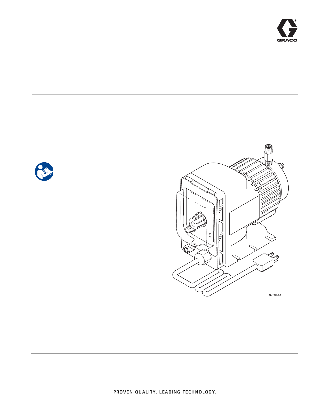
Mongoose
Chemical Metering
3A4131H
Pump
Electric metering pump for injecting chemicals at well sites. For professional use only.
Not approved for use in explosive atmospheres or hazardous locations.
See page 2 for model information, including maximum working
pressures.
Important Safety Instructions
Read all warnings and instructions in this manual.
Save all instructions.
EN
Page 2
3008494
Conforms to UL STD 778
Certified to CSA C22.2 No. 108
Contents
Warnings . . . . . . . . . . . . . . . . . . . . . . . . . .3
Installation . . . . . . . . . . . . . . . . . . . . . . . . . . . . . . . . 5
Grounding . . . . . . . . . . . . . . . . . . . . . . . . . . . . . . 5
Flush Before Using Equipment . . . . . . . . . . . . . . 5
Location Requirements . . . . . . . . . . . . . . . . . . . . 5
Plumbing Requirements for Stainless Steel /
Plastic Fluid Sections . . . . . . . . . . . . . . . . . . 5
Component Identification . . . . . . . . . . . . . . . . . . 6
Mounting and Chemical Supply Connection . . . . 7
Typical Installation . . . . . . . . . . . . . . . . . . . . . . . 8
Troubleshooting . . . . . . . . . . . . . . . . . . . . . . . . . . . 11
Repair . . . . . . . . . . . . . . . . . . . . . . . . . . . . . . . . . . . 13
Stainless Steel Fluid End Repairs . . . . . . . . . . . 13
Plastic Fluid End Repairs . . . . . . . . . . . . . . . . . 14
Parts . . . . . . . . . . . . . . . . . . . . . . . . . . . . . . . . . . . . 17
Mongoose Metering Pump . . . . . . . . . . . . . . . . 17
Kits and Accessories . . . . . . . . . . . . . . . . . . . . . . . 19
Dimensions . . . . . . . . . . . . . . . . . . . . . . . . . . . . . . . 20
Technical Data . . . . . . . . . . . . . . . . . . . . . . . . . . . . 21
Graco Standard Warranty . . . . . . . . . . . . . . . . . . . 22
Operation . . . . . . . . . . . . . . . . . . . . . . . . . . . . . . . . . 9
Pressure Relief Procedure . . . . . . . . . . . . . . . . . 9
Flush the Equipment . . . . . . . . . . . . . . . . . . . . . . 9
Prime the Pump . . . . . . . . . . . . . . . . . . . . . . . . . 9
Adjust Feed Rate . . . . . . . . . . . . . . . . . . . . . . . 10
Adjust Stroke Length . . . . . . . . . . . . . . . . . . . . . 10
Calculate Output . . . . . . . . . . . . . . . . . . . . . . . . 10
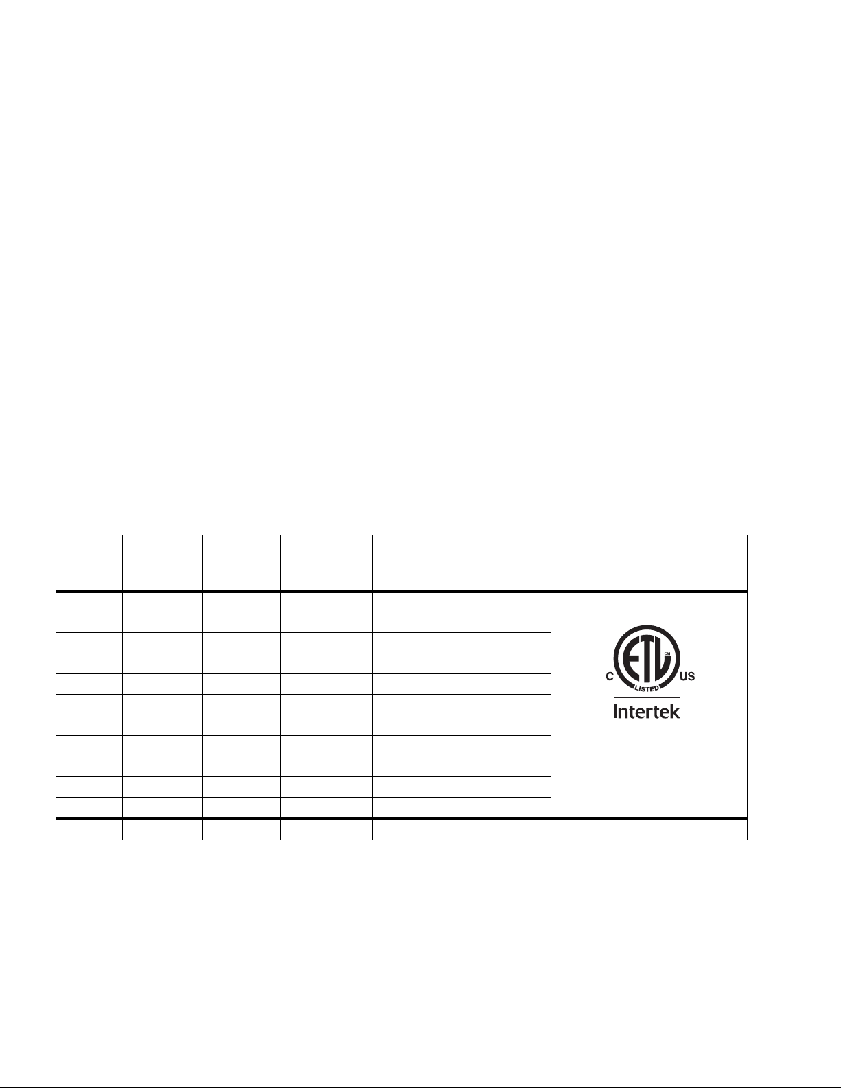
Models and Approvals
Fluid
Section
Models Voltage
A21000 120 VAC 316 SST 17 250 (1.72, 17.2)
A21001 120 VAC 316 SST 17 250 (1.72, 17.2)
A21004 230 VAC 316 SST 17 250 (1.72, 17.2)
A21008 120 VAC PVDF 17 250 (1.72, 17.2)
A21009 120 VAC PVDF 15 150 (1.03, 10.3)
A21010 120 VAC PVDF 30 110 (0.76, 7.6)
A21011 120 VAC PVDF 45 75 (0.52, 5.2)
A21012 230 VAC PVDF 17 250 (1.72, 17.2)
A21013 230 VAC PVDF 15 150 (1.03, 10.3)
A21014 230 VAC PVDF 30 110 (0.76, 7.6)
A21015 230 VAC PVDF 45 75 (0.52, 5.2)
A21016 12 VDC 316 SST
Material
Flow (GPD)
10 140 (0.97, 9.7)
Maximum Working Pressure
psi (MPa, bar)
Approvals
2 3A4131H
Page 3
Warnings
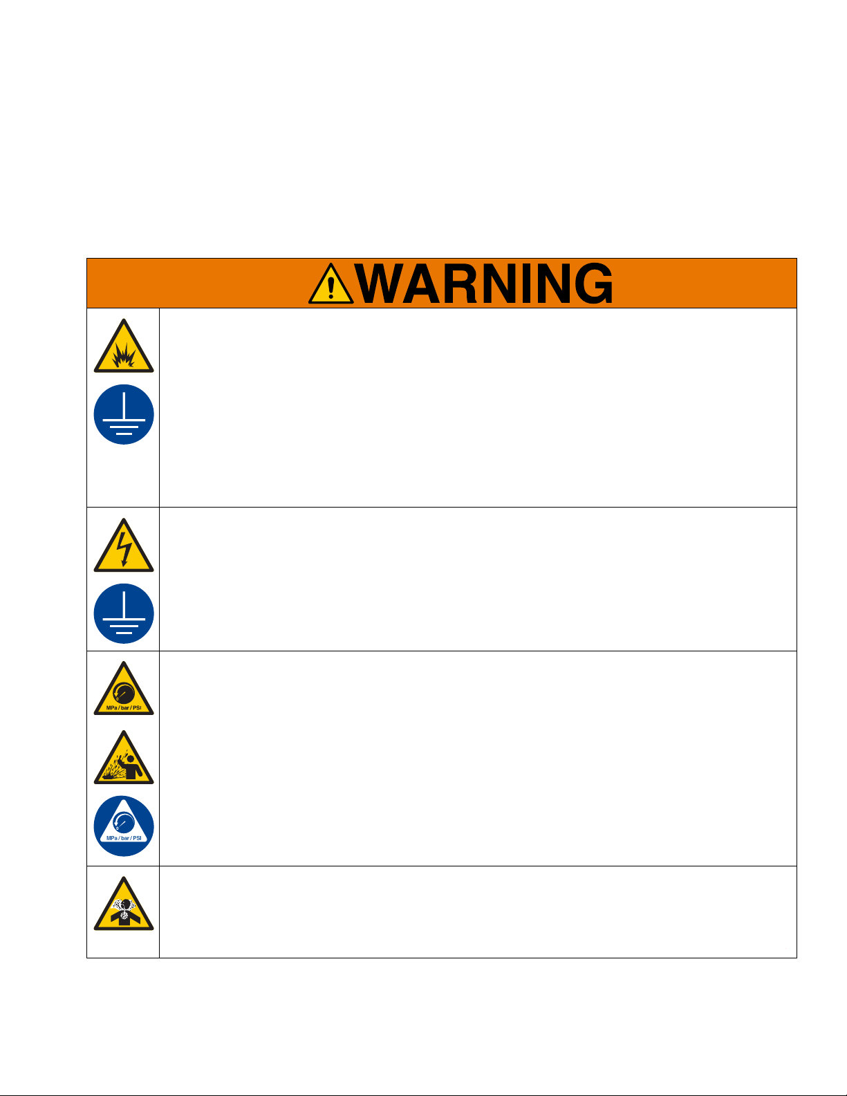
Warnings
The following warnings are for the setup, use, grounding, maintenance, and repair of this equipment. The exclamation point symbol alerts you to a general warning and the hazard symbols refer to procedure-specific risks. When
these symbols appear in the body of this manual or o n warning labels, refer back to these Warnings. Product-specific
hazard symbols and warnings not covered in this section may appear throughout the body of this manual where
applicable.
FIRE AND EXPLOSION HAZARD
When flammable fluids are present in the work area be aware that flammable fumes can ignite or
explode. To help prevent fire and explosion:
• Use equipment only in well ventilated area.
• Eliminate all ignition sources, such as cigarettes and portable electric lamps.
• Ground all equipment in the work area.
• Keep work area free of debris, including rags and spilled or open containers of solvent.
• Do not plug or unplug power cords or turn lights on or off when flammable fumes are present.
• Use only grounded hoses.
• Stop operation immediately if static sparking occurs or you feel a shock. Do not use equipment until
you identify and correct the problem.
• Keep a working fire extinguisher in the work ar ea .
ELECTRIC SHOCK HAZARD
This equipment must be grounded. Improper grounding, setup, or usage of the system can cause electric shock.
• Turn off and disconnect power cord before servicing equipment.
• Connect to grounded outlet protected by Class A GFCI.
• Use only 3-wire extension cords.
• Ensure ground prongs are intact on power and extension cords.
PRESSURIZED EQUIPMENT HAZARD
Fluid from the equipment, leaks, or ruptured components can splash in the eyes or on skin and cause
serious injury.
• Follow the Pressure Relief Procedure when you stop spraying/dispensing and before cleaning,
checking, or servicing equipment.
• Tighten all fluid connections before operating the equipment.
• Check hoses, tubes, and couplings daily. Replace worn or damaged parts immediately.
TOXIC FLUID OR FUMES HAZARD
Toxic fluids or fumes can cause serious injury or death if splashed in the eyes or on skin, inhaled, or
swallowed.
• Read Safety Data Sheet (SDS) to know the specific hazards of the fluids you are using.
• Store hazardous fluid in approved containers, and dispose of it according to applicable guidelines.
3A4131H 3
Page 4
Warnings
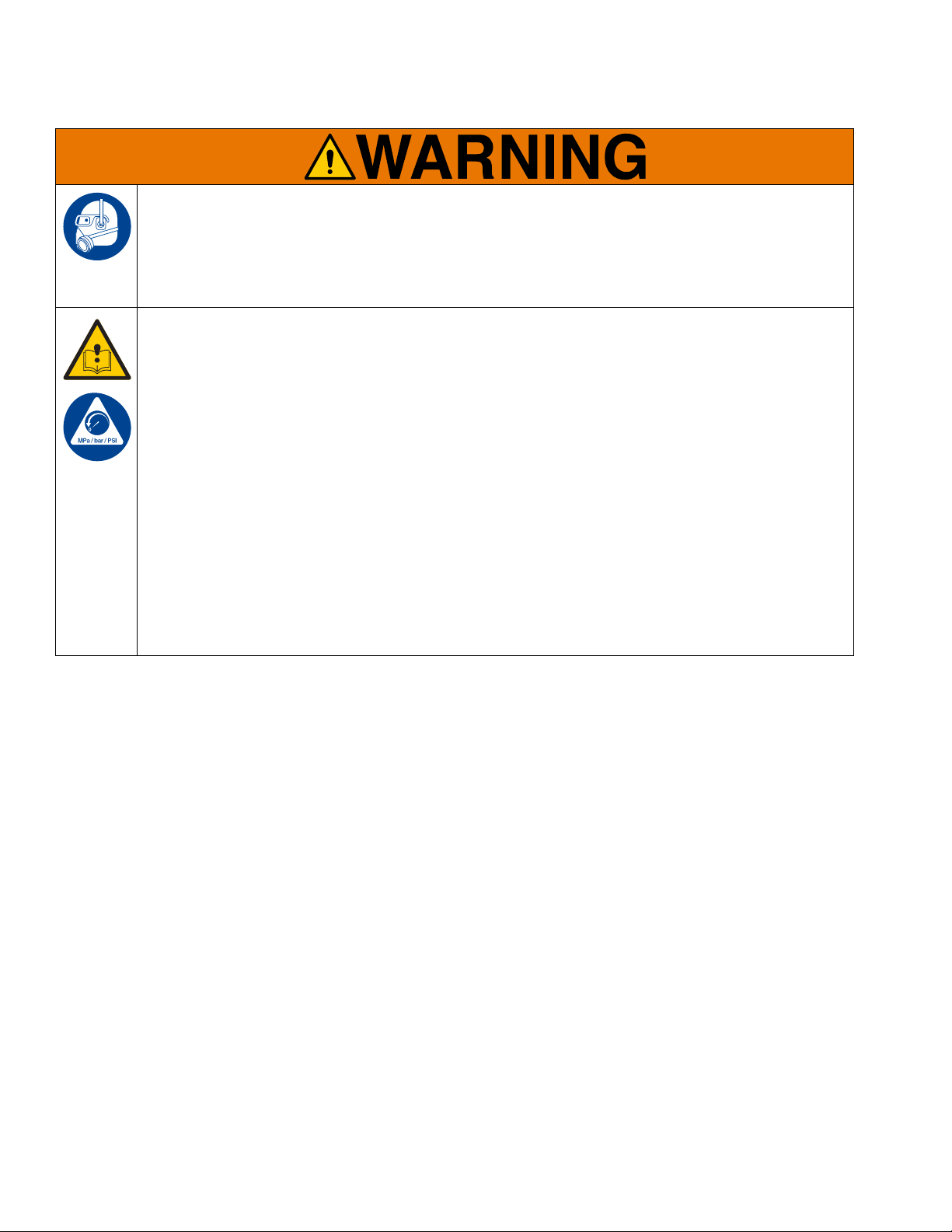
PERSONAL PROTECTIVE EQUIPMENT
Wear appropriate protective equipment when in the work area to help prevent serious injury, including
eye injury, hearing loss, inhalation of toxic fumes, and burns. Protective equipment includes but is not
limited to:
• Protective eyewear, and hearing protection.
• Respirators, protective clothing, and gloves as recommended by the fluid and solvent manufacturer.
EQUIPMENT MISUSE HAZARD
Misuse can cause death or serious injury.
• Do not operate the unit when fatigued or under the influence of drugs or alcohol.
• Do not exceed the maximum working pressure or temperature rating of the lowest rated system component. See Technical Data in all equipment manuals.
• Use fluids and solvents that are compatible with equipment wetted parts. See Technical Data in all
equipment manuals. Read fluid and solvent manufacturer’s warnings. For complete information
about your material, request Safety Data Sheet (SDS) from distributor or retailer.
• Turn off all equipment and follow the Pressure Relief Procedure when equipment is not in use.
• Check equipment regularly. Repair or replace wo rn or damaged parts immediately with genuine man ufacturer’s replacement parts only.
• Do not alter or modify equipment. Alterations or modifications may void agency approvals and create
safety hazards.
• Make sure all equipment is rated and approved for the environment in which you are using it.
• Use equipment only for its intended purpose. Call your distributor for information.
• Route hoses and cables away from traffic areas, sharp edges, moving parts, and hot surfaces.
• Do not kink or over bend hoses or use hoses to pull equipment.
• Keep children and animals away from work area.
• Comply with all applicable safety regulation s.
4 3A4131H
Page 5
Installation
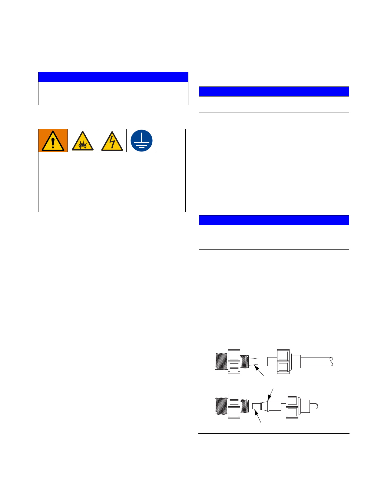
3/8 in.
1/4 in.
Tubing must slip over nipple
End of the tubing
1/4 in. tubing adapter
Installation
NOTICE
It is recommended that adequate surge protection be used
in order to protect products from voltage changes in your
application.
Grounding
The equipment must be grounded to reduce the risk
of static sparking and electric shock. Electric or static
sparking can cause fumes to ignite or explode.
Improper grounding can cause electric shock.
Grounding provides an escape wire for the electric
current.
• Never remove ground wire from plug. Connect to
grounded outlet protected by Class A GFCI.
Pump: grounded through electrical cord.
Fluid lines: use only electrically conductive lines.
Fluid supply container: follow local code.
NOTICE
In order to prevent over pumping at low back pressure (less
than 50 PSI) install an inline check valve on the outlet line.
Flush Before Using Equipment
The equipment was tested with water. To avoid contaminating your fluid with water, flush the equipm en t with a
compatible solvent before using the equipm en t. See
Flush the Equipment, page 9.
Location Requirements
Select a mounting location convenient to both the chemical supply and a source of power for the pump.
NOTICE
Do not install the pump in a location where the ambient
temperature exceeds 120
will affect the output as well as the useful life of the pump.
o
F (50o C). Higher temperatures
Plumbing Requirements for Stainless Steel / Plastic Fluid Sections
The Mongoose pump uses carefully matched components to achieve a predictable metering output. This
predictability can only be maintained if all fitting sizes
remain unaltered.
All connections should be double checked to insure
against leakage. If hazardous chemicals are being
pumped, use shielding around outlet fluid lines. NOTES:
• There is an approximate 2.5 psi capability lost for
every 1 foot of vertical rise of the outlet fluid line to
the injection point.
• Do not attempt to reduce tubing size; this may
reduce performance of unit.
Stainless Steel Fluid Section Models
Inlet and outlet valves are both 1/4 in. NPT fittings.
NOTE: Apply PTFE tape to threads on NPT fittings.
Plastic Fluid Section Models
Inlet and outlet valves use 3/8 in. or 1/4 in. tubing connectors, and 3/8 in. or 1/4 in. tubing. See F
IG. 1.
NOTE: The prime/bleed valve on the plastic fluid section
includes a 1/16 in. clear poly tubing. This tubing is to be
used only with the prime/bleed valve and is not intended
for pressurized use. Do not use with the inlet and outlet
valves.
Tighten connectors no more than a 1/4 turn after the
connection feels snug. Hand tighten only. Do not overtighten.
NOTE: Do not apply PTFE tape to threads.
FIG. 1: Tubing Connections
3A4131H 5
Page 6
Installation
1
B
A
C
4
C
D
3
2
9
11
B
A
1
102
103
109
104
E
D
11
2
E
1
B
A
C
9
4
3
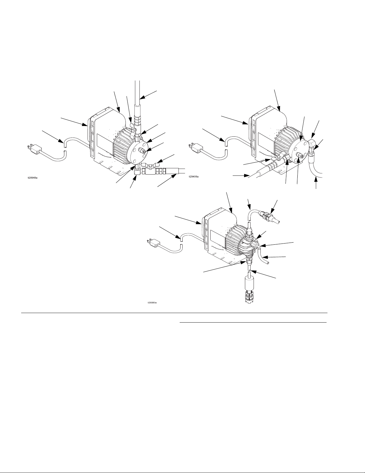
Stainless Steel Fluid End
Plastic Fluid End
(Models A21000, A21001, A21004, A21016)
(Models A21008, A21009, A21010,
A21011, A21012, A21013, A21014,
A21015)
Standard Configuration
Alternate Configuration
Clear
tubing
White
tubing
White
tubing
Component Identification
FIG. 2: Component Identification
Components Supplied by Graco
The following components are supplied by Graco:
1 Motor Assembly
2 Inlet Valve (stainless steel fluid end)
3 Outlet Valve (stainless steel fluid end)
4 Prime/Bleed Valve (stainless steel fluid end; not available
on A21001)
9 Stainless Steel Fluid End
11 Elbow Fitting (stainless steel only; not supplied with
A21001)
102 Inlet Valve Assembly (plastic fluid end, includes white tub-
6 3A4131H
ing)
103 Outlet Valve Assembly (plastic fluid end, includes white tub-
ing)
104 Prime/Bleed Valve Assembly (plastic fluid end, includes
clear poly tubing)
109 Plastic Fluid End
A Control Panel
B Power Cord
Components Supplied by Customer
The following components are required to be supplied by the
customer:
C Shutoff Valve (inlet/outlet, stainless steel fluid end)
D Inlet Fluid Line (stainless steel fluid end)
E Outlet Fluid Line (stainless steel fluid end)
Page 7
Installation
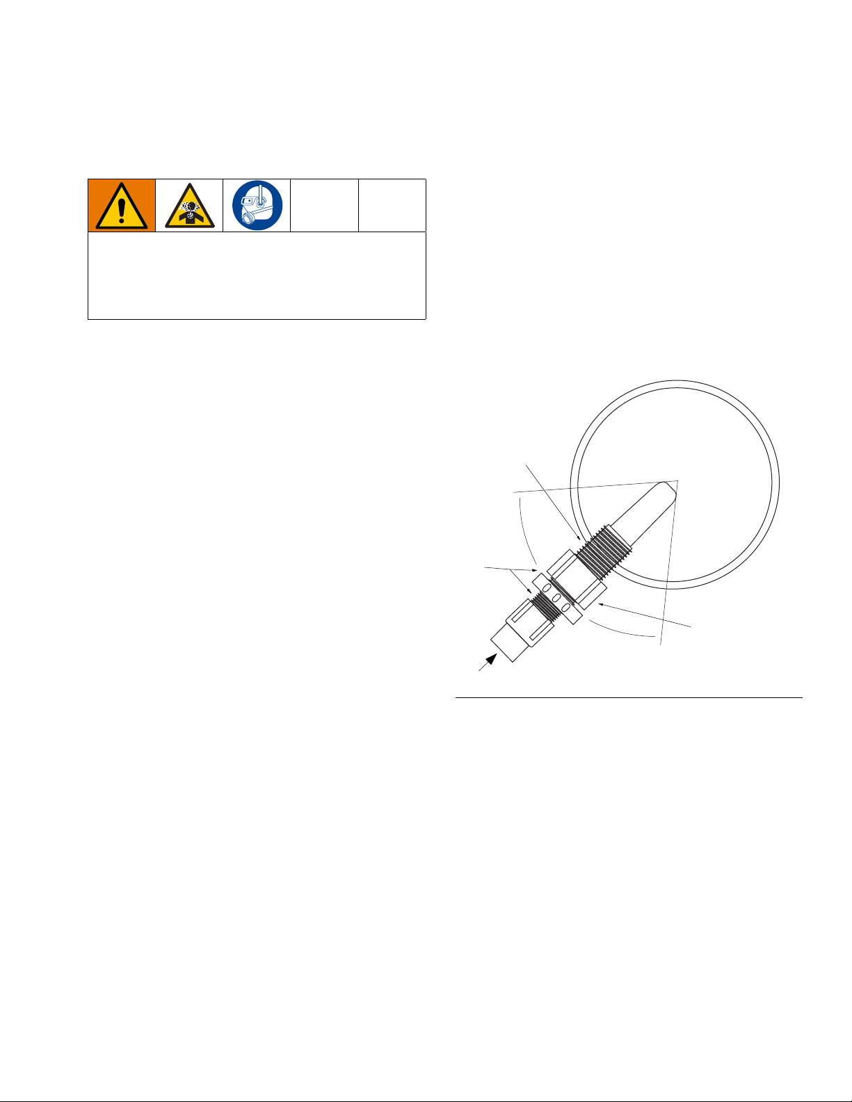
E
Use PTFE tape on
these threads only
Pipe Cross
Section
Injection
Check Valve
Do not use
PTFE tape here
Mounting and Chemical Supply
Connection
Failure of the diaphragm or a rupture in the fluid lines
may cause exposure to toxic fumes or a loss of solution in the tank. Install a fluid line shutoff valve as
close to the chemical tank as possible to minimize the
loss of, and exposure to, potentially toxic chemicals.
Flooded Suction Mounting
The fluid end (9) of the pump, shown in FIG. 2, is set up
to accommodate mounting of the pump next to the
chemical supply container (G), shown in F
NOTE: The inlet valve (2 or 102) must be kept in a vertical position for proper operation. The fluid end (9 or 109)
can be removed and rotated 90° if needed.
Suction Lift Mounting (Plastic Fluid Section
only)
IG. 4.
Injection Check Valve Connection (Plastic
Fluid Section only)
The injection check valve is designed to prevent a back
flow and to inject chemical into a piping system. This
valve must be mounted within 45° of vertical (see F
3).
1. Install the 1/2 in. NPT end into the piping system.
Apply PTFE tape to this end only.
2. Connect the outlet fluid line (E) from the Mongoose
pump to the to the other end of the injection check
valve.
IG.
The pump is mounted on top of a chemical supply container, shown in F
pump to the bottom of the container does not exceed
5 ft.
A weight is provided to hold the inlet fluid line (D) and
foot valve (H) in a vertical position at the bottom of the
container. Keep the inlet fluid line (D) relatively short,
and avoid high spots or bends.
NOTE: Do no allow the foot valve (H) to lie horizon ta lly
in the tank. This defeats the action of the valve and
causes the pump to lose prime.
IG. 4, so that the distance from the
FIG. 3: Injection Valve Connection
Three-Function Valve Injection Assembly
(Plastic Fluid Section only; Optional)
The optional three-function valve injection assembly
provides three functions in one injection valve asse mbly.
• Anti-siphon - which allows metering of liquids into
the inlet side of a circulating pump. It provides protection against an accidental application of suction
pressure at the fluid injection point. A PTFE coated
diaphragm provides a positive anti-siphon action.
• Back pressure - which permits metering into atmospheric discharge (such as an open container) without overpumping.
• Line check - which permits removal of outlet tubing
without release of system fluid.
3A4131H 7
Page 8

Installation
C
E
B
F
C
D
G
C
Flooded Suction Installation
Suction Lift Installation
G
H
D
E
F
No more than
5 ft. from pump
to bottom of
container
Typical Installation
FIG. 4: Typical Installation
FIG. 4 shows two examples of an installation with a Mongoose chemical metering pump. Your installation may differ
from what is shown here. The Mongoose pump (F) and the attached power cord (B) are the only components in F
4 supplied by Graco. All other components are supplied by customer.
Key:
B Power Cord
C Shutoff Valve (Inlet/Outlet)
D Inlet Fluid Line
E Outlet Fluid Line
F Mongoose Pump
G Chemical Supply Container
HFoot Valve
IG.
8 3A4131H
Page 9

Operation
Operation
Pressure Relief Procedure
Follow the Pressure Relief Procedure whenever
you see this symbol.
This equipment stays pressurized until pressure is
manually relieved. To help prevent serious injury from
pressurized fluid, such as splashing fluid, follow the
Pressure Relief Procedure when you stop dispensing and before cleaning, checking, or servicing the
equipment.
NOTE: Always discharge fluid into an approved container or location.
1. Turn SPEED knob (H) to off and disconnect power
cord (B).
2. Shut off the inlet and outlet lines using shutoff
valves (C).
3. Slowly crack the fitting connected to the outlet check
valve to relieve downstream fluid pressure.
4. Run the pump until the dispensed fluid is predominately flushing fluid.
5. Follow the Pressure Relief Procedure.
Prime the Pump
1. Connect power (B) to the pump.
2. Set the STROKE % knob (J) to 100%. (See F
on page 10.)
3. Set the SPEED knob (H) to maximum cycles per
second.
While pump is operating, if fluid begins moving, no further priming is required.
If fluid is not moving, open prime/bleed valve (4 or 104)
approximately one turn until fluid begi ns to move. When
the inlet fluid line (D) fills, close prime/bleed valve (4 or
104).
IG. 5
Flush the Equipment
To avoid fire and explosion, always ground e quipment
and waste container. To avoid static sparking and
injury from splashing, always flush at the lowest possible pressure.
• Flush with a fluid that is compatible with the fluid
being dispensed and the equipment wetted par ts.
1. Follow the Pressure Relief Procedure.
2. Connect inlet fluid line (D) to the supply source of
the flushing fluid.
3. Connect outlet fluid line (E) to a waste container.
NOTICE
Do not overtighten prime/bleed valve. Damage may occur.
3A4131H 9
Page 10

Operation
J
H
Adjust Feed Rate
The Mongoose pump allows for the exact setting of the
pump’s SPEED knob (H) on the pump’s control panel.
IG. 5.
See F
Adjust Stroke Length
The stroke length can be adjusted on the Mongoose
pump. This is a mechanical adjustment made using
STROKE % knob (J) on the control panel.
NOTICE
To avoid damage to the pump, this adjustment
should only be made while the pump is running at a
high-stroking rate.
Calculate Output
A pump’s output per minute can be determined by dividing the maximum rated gallons per day by 1440 (minutes per day).
For example, a 30 gallons per day (gpd) pump at a maximum stroke length and speed setting of 125 cycles per
minute (cpm) will pump 0.000167 gallons per stroke
(gps).
30 gpd ÷ 1440 min/day = 0.0208 gpm ÷ 125 spm =
0.000167 gal/stroke
FIG. 5: Mongoose Control Panel
NOTE: Standard cycles per minute settings available
are: 1, 2, 3, 4, 5, 6, 7, 8, 10, and increase by 5 thereafter
up to the maximum of 125.
With this value and the pump’s speed setting (cycles pe r
minute) you can calculate your pump’s output at it’s
rated pressure.
A 30 gpd pump set at 50 cycles per minute:
50 cpm x .000167 gps x 1440 min/day = 12.02 gpd
Reducing the stroke length will reduce the pump’s output again. If the example pump above had it’s str ok e
length reduced to 50% the 12.02 gallons per day ou tput
is reduced to 6.01. (Example: 12.02 gpd x 0.50 = 6.01
gpd).
A higher product viscosity will reduce the output. Pressures lower than the pump’s rating can increase the output.
10 3A4131H
Page 11

Troubleshooting
Problem Cause Solution
Troubleshooting
1. Follow Pressure Relief Procedure, page 9, before
checking pump.
Pump does not achieve or maintain
prime
Insufficient fluid Stroke adjustment set too low Check operation of STROKE %
Air trapped in inlet line Straighten inlet line to eliminate high
spots.
Worn or contaminated check valves Inspect check valves in fluid end for
cleanliness.
Excessive lift Verify the appropriate lift for the liquid
being pumped. Maximum suction lift
is 5 ft. with water or liquids of similar
specific gravity; though less with
heavier liquids, such as acids. Mount
the pump in a lower position relative
to the chemical container.
Suction fittings not properly tightened Check fittings. Overtightening may
cause restriction. Conversely, if any
leakage occurs, the pump will suck
air and fail to prime.
Split or pinch in inlet tube Inspect inlet tube through its full
length to assure there are no splits at
the connections or other restrictions.
Move objects or equipment which
impinges upon the inlet tube, or
reroute as required to assure a
smooth transition from foot valve to
pump.
Low chemical level Check fluid level in chemical supply
tank.
knob. If pump delivers too low adjustable rate, check settings. Readjust as
required.
Worn or contaminated check valves Inspect, clean, or replace as neces-
sary.
Obstruction in inlet line Check inlet line for obstructions, clog-
ging, kinks, or pinch points.
Clogged foot valve screen Clean or replace foot valve screen.
Output (system) pressure too high Relocate the injector to a lower pres-
sure part of the system.
Diaphragm worn or torn Replace diaphragm.
Blown fuse Replace fuse with like kind.
3A4131H 11
Page 12

Troubleshooting
Problem Cause Solution
Excessive fluid Excessive stroke rate Lower the stroke rate if adjustable on
your pump.
Improper stroke length Reduce stroke length.
Pump will not pump System pressure too high Check system pressure to assure
that it is within system-rated parameters of the pressure.
Diaphragm improperly installed Ensure the diaphragm is screwed
fully onto shaft.
Check valves worn or clogged Clean or replace as required.
Pump will not run Pump not turned on or plugged in Check outlet with meter to assure
that correct voltage is present, and
that power supply cord is in good
condition and plugged in.
Blown fuse Replace fuse with like kind.
Excessive noise Pump not primed Prime pump.
12 3A4131H
Page 13

Repair
Repair
Stainless Steel Fluid End
Repairs
NOTE: The following procedures apply only to models
with stainless steel fluid ends (A21000, A21001,
A21004, and A21016).
Replacing the Diaphragm
1. Follow the Pressure Relief Procedure, page 9.
2. Flush the Equipment, page 9.
3. Disconnect the power (B).
4. Drain the fluid from the outlet fluid line (E).
5. Disconnect the outlet fluid line (E).
6. Remove the four fluid end screws (10) from the fluid
end (9).
7. Remove the fluid end from the motor assembly (1).
Replacing the Inlet Valve
1. Follow the Pressure Relief Procedure, page 9.
2. Flush the Equipment, page 9.
3. Disconnect the power (B).
4. Close the inlet shutoff valve (C).
5. Disconnect the shutoff valve (C) from the inlet
valve (2); or elbow fitting (11), if attached.
6. Remove the elbow fitting (11), if attached. Inspect
and replace, if necessary.
7. Remove the inlet valve (2) from the fluid end (9).
Inspect the inlet valve and replace, if necessary.
8. Apply PFTE tape on the threads of the inlet
valve (2).
9. Reattach the inlet valve (2) to the fluid end (9).
NOTE: The inlet valve (2) has flow arrow that must point
towards the fluid end (9).
10. Reattach the elbow fitting (11), if used, to the inlet
valve (2).
8. Unscrew the diaphragm (7) counterclockwise from
the pump shaft.
9. Inspect the pump shaft and support ring (8) for damage.
10. Screw the new diaphragm (7) clockwise onto the
pump shaft.
11. Replace the fluid end (9) and the four screws (10).
Tighten the screws evenly.
12. Reconnect the outlet fluid line (E).
13. Reconnect power (B).
14. Prime the Pump, page 9.
NOTE: Tighten fluid end screws (10) after the pump’s
initial week of operation.
11. Reconnect the shutoff valve (C).
12. Reconnect the power (B).
13. Prime the Pump, page 9.
3A4131H 13
Page 14

Repair
Replacing the Outlet Valve
1. Follow the Pressure Relief Procedure, page 9.
2. Flush the Equipment, page 9.
3. Disconnect the power (B).
4. Close the inlet shutoff valve (C).
5. Disconnect the shutoff valve (C) from the outlet
valve (3).
6. Remove the outlet valve (3) from the fluid end (9).
Inspect and replace, if necessary.
7. Apply PTFE tape on the threads of the outlet
valve (3).
8. Reattach the inlet valve (3) to the fluid end (9).
NOTE: The outlet valve (3) has flow arrow that must
point away from the fluid end (9).
9. Reconnect the shutoff valve (C).
10. Reconnect the power (B).
11. Prime the Pump, page 9.
Replacing the Prime/Bleed Valve
Plastic Fluid End Repairs
NOTE: The following procedures apply only to models
with plastic fluid ends (A21008, A21009, A21010,
A21011, A21012, A21013, A21014, A21015).
Replacing the Diaphragm
1. Follow the Pressure Relief Procedure, page 9.
2. Flush the Equipment, page 9.
3. Disconnect the power (B).
4. Drain the fluid from the outlet fluid line (E).
5. Disconnect the outlet fluid line (E).
6. Remove the four fluid end screws (110) from the
fluid end (109).
7. Remove the fluid end (109) from the motor assembly (1).
8. Unscrew the diaphragm (7) counterclockwise from
the pump shaft.
1. Follow the Pressure Relief Procedure, page 9.
2. Flush the Equipment, page 9.
3. Disconnect the power (B).
4. Close the inlet shutoff valve (C).
5. Remove the prime/bleed valve (4) from the fluid end
(9). Inspect and replace, if necessary.
6. Apply PTFE tape on the threads of the prime/b le ed
valve (4).
7. Reattach the prime/bleed valve (4) to the fluid
end (9).
8. Reconnect the power (B).
9. Prime the Pump, page 9.
9. Inspect the pump shaft and support ring (8) for damage.
10. Screw the new diaphragm (7) clockwise onto the
pump shaft.
11. Replace the fluid end (109) and the four screws
(110). Tighten the screws evenly.
12. Reconnect the outlet fluid line (E).
13. Reconnect power (B).
14. Prime the Pump, page 9.
NOTE: Tighten fluid end screws (110) after the pump’s
initial week of operation.
14 3A4131H
Page 15

Repair
Ball check cartridge in this end of valve
3/8 in.
1/4 in.
Replacing the Inlet Valve
1. Follow the Pressure Relief Procedure, page 9.
2. Flush the Equipment, page 9.
3. Disconnect the power (B).
4. Remove the inlet valve (102) from the from the fluid
end (109).
5. Remove the o-ring from the inlet port of the fluid
end (109).
6. Reattach the inlet valve (102) to the fluid en d (1 09 ) .
7. Reconnect the power (B).
8. Prime the Pump, page 9.
Replacing the Outlet Valve
1. Follow the Pressure Relief Procedure, page 9.
2. Flush the Equipment, page 9.
3. Disconnect the power (B).
Replacing the Valve Ball Check Cartridge
The following procedure is the same for all plastic valve
assemblies: inlet (102), outlet (103), foot (111), injection
(112), and three-function (113). See the Model A21008
(Plastic Fluid End) shown parts diagram on page 18.
Follow the Pressure Relief Procedure, page 9. is
explained on page 15.
The part of the valve that holds the ball check cartridge
is interchangeable among each of the valve assemblies.
The ball check cartridge is in the end away from any
connected tubing. See F
IG. 6.
4. Remove the outlet valve (103) from the from the
fluid end (109).
5. Remove the o-ring from the outlet port of the fluid
end (109).
6. Reattach the outlet valve (103) to the flui d
end (109).
7. Reconnect the power (B).
8. Prime the Pump, page 9.
FIG. 6: Location of Valve Ball Check Cartridge
1. Follow the Pressure Relief Procedure, page 9.
2. Flush the Equipment, page 9.
3. Disconnect the power (B).
4. Disconnect the valve at the end away from the tubing. Verify that the ball check o-ring is still attached
to, or came out with, the ball check cartridge (114).
5. Use a hooked tool to pull out the ball check
cartridge (114). Verify that the second o-ring is not
left in the valve.
6. Discard the ball check cartridge (114) and o-rings.
7. Attach new o-rings to both ends of the new ball
check cartridge (114).
3A4131H 15
Page 16

Repair
NOTICE
To ensure the proper function of the pump and to
avoid potential damage, consider the direction of flow
before inserting the ball check cartridge (114) into the
valve. The cartridge has a hole on each end, with one
being larger than the other. The cartridge needs to be
oriented so that the flow goes in the larger hole and
out the smaller.
8. Insert the ball check cartridge (114), with o-rings,
into the end of the valve.
9. Reconnect the valve.
10. Repeat steps 4-9 for each valve ball check cartridge
(114) being replace.
11. Reconnect the power (B).
12. Prime the Pump, page 9.
Replacing the Fluid End Ball Check
Cartridges
The following procedure applies only to the two ball
check cartridges (114 and 115) in the plastic fluid end
(109). Replacing the Valve Ball Check Cartridge is
explained on page 15.
NOTICE
To ensure the proper function of the pump and to
avoid potential damage, consider the dire ction of flow
before inserting each ball check cartridge (114 and
115) into the fluid end ports. Each cartridge has a
hole on each end, with one being larger than the
other. The cartridges need to be oriented so that the
flow goes in the larger holes and out the smaller.
8. Insert the ball check cartridge (114), with o-rings,
into the inlet port of the fluid end (109).
9. Reconnect the inlet valve (102) to the inlet port on
the fluid end (109).
10. Align the priming hole on the side of the ball check
cartridge (115) with the prime/bleed valve (104)
before inserting the cartridge (115) into the outlet
port of the fluid end (109).
11. Reconnect the outlet valve (103) to the outlet port
on the fluid end (109).
12. Reconnect the power (B).
13. Prime the Pump, page 9.
Replacing the Prime/Bleed Valve
1. Follow the Pressure Relief Procedure, page 9.
2. Flush the Equipment, page 9.
3. Disconnect the power (B).
4. Disconnect both the inlet valve (102) and the outlet
valve (103) at the end away from their respective
tubing.
5. Use a hooked tool to pull the ball check cartridges
(114 and 115) from the inlet and outlet ports,
respectively, of the fluid end (109). Verify that both
o-rings on both cartridges are removed.
6. Discard the ball check cartridges (114 and 115) and
o-rings.
7. Attach new o-rings to both ends of each new ball
check cartridge (114 and 115).
1. Follow the Pressure Relief Procedure, page 9.
2. Flush the Equipment, page 9.
3. Disconnect the power (B).
4. Remove the prime/bleed valve (104) from the fluid
end (9). Inspect and replace, if necessary.
5. Reattach the prime/bleed valve (104 ) to th e flu id
end (109).
6. Reconnect the power (B).
7. Prime the Pump, page 9.
16 3A4131H
Page 17

Parts
2
1
3
4†
7
5
8
9
10
1
1
Apply PTFE tape to threads
1
11‡
6
(opposite ref. 5)
Mongoose Metering Pump
Model A21000 (Stainless Steel Fluid End) shown
Parts
Mongoose Metering Pump Parts List (Stainless Steel Fluid End)
Ref. Part Description Qty
1 -- Motor assembly 1
2 B32279 Inlet check valve 1
3 B32280 Outlet check valve 1
4† B32191 Prime/bleed valve 1
5 -- Branding label 1
6 17M292 Warning label 1
7 B32281 Diaphragm; 75, 110 psi 1
B32282 Diaphragm; 150, 250 psi 1
8 -- Support ring 1
9 -- Fluid end 1
10 -- Fluid end screws 4
11‡ 17M529 Elbow fitting 1
3A4131H 17
Replacement Warning label is available at no cost.
† Not available with A21001.
‡ Not provided with A21001.
Page 18

Parts
1
103*
104*
7*
5
8
109*
110*
1
6
(opposite ref. 5)
102*
112
114
115
114
114
111
Apply PTFE tape only to
threads on the end of the injection
valve assembly.
1
Weight
Priming Hole
Model A21008 (Plastic Fluid End) shown
18 3A4131H
Page 19

Kits and Accessories
Mongoose Metering Pump Parts List
(Plastic Fluid End)
Ref. Part Description Qty
1 -- Motor assembly 1
5 -- Branding label 1
6 17M292 Warning label 1
7* B32281 Diaphragm; 75, 110 psi 1
B32282 Diaphragm; 150, 250 psi 1
8 -- Support ring 1
102* B32290 Inlet check valve assembly, 3/8
in. (includes tubing)
B32291 Inlet check valve assembly, 1/4
in. (includes tubing)
103* B32292 Outlet check valve assembly,
3/8 in. (includes tubing)
B32293 Outlet check valve assembly,
1/4 in. (includes tubing)
104* B32296 Prime/bleed valve assembly
(includes clear poly tubing)
109* -- Fluid end 1
110* -- Fluid end screws 4
111 B32288 Foot valve assembly, 3/8 in. 1
B32289 Foot valve assembly, 1/4 in. 1
112 B32286 Injection valve assembly, 3/8 in. 1
B32287 Injection valve assembly, 1/4 in. 1
113 B32294 Three-function valve assembly,
3/8 in. (not shown)
B32295 Three-function valve assembly,
1/4 in. (not shown)
114† B32298 Ball check cartridge assembly 5
115† B32299 Ball check cartridge assembly,
with priming hole
1
1
1
1
1
1
1
1
Kits and Accessories
Part No. Description
B32283* Pump Kit, 110 psi, 3/8 in. tubing
B32284* Pump Kit, 150 psi, 3/8 in. tubing
B32285* Pump Kit, 250 psi, 1/4 in. tubing
B32297† Ball Check Kit (six ball check cartridge
assemblies)
* Includes 7, 102, 103, 104, 109, and 110.
† Includes 114 and 115.
Replacement Warning label is available at no cost.
* Included in Pump Kits B32283, B32284, and
B32285.
† Included in Ball Check Kit B32297.
3A4131H 19
Page 20

Dimensions
Dimensions
FIG. 7: Mongoose Pump Dimensions
A B C D
10.6 in.
(26.9 cm)
20 3A4131H
7.5 in.
(19.0 cm)
5.0 in.
(12.7 cm)
4.13 in
(10.5 cm)
Page 21

Technical Data
Mongoose Chemical Metering Pump
US Metric
Maximum fluid working pressure See Models and Approvals, page 2.
Maximum cycle rate (A21011 & A21015) 160 cpm
Maximum cycle rate (all except A21011 &
A21015)
Input Voltage (A21016) 10.5 - 16.0 VDC
Input Voltage (A21000, A21001, A21008,
A21009, A21010, A21011)
Input Voltage (A21004, A21012, A21013,
A21014, A21015)
Rated Amperage .35 A
Fuse Fast Blow 3A Barrel Style 314
Environmental temperature range -40°– 120°F -40°– 50°C
Inlet/Outlet Sizes
Stainless Steel Fluid Section
Fluid inlet/outlet size (A21000, A21001,
A21004, A21016)
Prime/bleed size 1/16 in. NPT
Plastic Fluid Section
Fluid inlet/outlet size (A21008 & A21012) 1/4 in. tubing
Fluid inlet/outlet size (A21009, A21010,
A21011, A21013, A21014, A21015)
Prime/bleed size 1/16 in. clear poly tubing
Wetted Parts
Diaphragm Seal Material PTFE
Check Valve Seal Material Plastic Fluid Sec-
tion
Check Valve Seal Material Stainless Steel
Fluid Section
Weight
All models 10 lbs. 4.5 kg
95 - 135 VAC; 50/60 Hz
(100 - 120 VAC recommended)
195 - 260 VAC; 50/60 Hz
(210 - 250 VAC recommended)
125 cpm
1/4 in. NPT
3/8 in. tubing
FKM
FFKM
Technical Data
3A4131H 21
Page 22

Graco Standard Warranty
Graco warrants all equipment referenced in this document which is manufactured by Graco and bearing its name to be free from defects in
material and workmanship on the date of sale to the original purchaser for use. With the exception of any special, extended, or limited warranty
published by Graco, Graco will, for a period of twelve months from the date of sale, repair or replace any part of the equipment determined by
Graco to be defective. This warranty applies only when the equipment is installed, operated and maintained in accordance with Graco’s written
recommendations.
This warranty does not cover, and Graco shall not be liable for general wear and tear, or any malfunction, damage or wear caused by faulty
installation, misapplication, abrasion, corrosion, inadequate or improper maintenance, negligence, accident, tampering, or substitution of
non-Graco component parts. Nor shall Graco be liable for malfunction, damage or wear caused by the incompatibility of Graco equipment with
structures, accessories, equipment or materials not supplied by Graco, or the improper design, manufacture, installation, operation or
maintenance of structures, accessories, equipment or materials not supplied by Graco.
This warranty is conditioned upon the prepaid return of the equipment claimed to be defective to an authorized Graco distributor for verification of
the claimed defect. If the claimed defect is verified, Graco will repair or replace free of charge any defective parts. The equipment will be returned
to the original purchaser transportation prepaid. If inspection of the equipment does not disclose any defect in material or workmanship, repairs
will be made at a reasonable charge, which charges may include the costs of parts, labor, and transportation.
THIS WARRANTY IS EXCLUSIVE, AND IS IN LIEU OF ANY OTHER WARRANTIES, EXPRESS OR IMPLIED, INCLUDING BUT NOT
LIMITED TO WARRANTY OF MERCHANTABILITY OR WARRANTY OF FITNESS FOR A PARTICULAR PURPOSE.
Graco’s sole obligation and buyer’s sole remedy for any breach of warranty shall be as set forth above. The buyer agrees that no other remedy
(including, but not limited to, incidental or consequential damages for lost profits, lost sales, injury to person or property, or any other incidental or
consequential loss) shall be available. Any action for breach of warranty must be brought within two (2) years of the date of sale.
GRACO MAKES NO WARRANTY, AND DISCLAIMS ALL IMPLIED WARRANTIES OF MERCHANTABILITY AND FITNESS FOR A
PARTICULAR PURPOSE, IN CONNECTION WITH ACCESSORIES, EQUIPMENT, MATERIALS OR COMPONENTS SOLD BUT NOT
MANUFACTURED BY GRACO. These items sold, but not manufactured by Graco (such as electric motors, switches, hose, etc.), are subject to
the warranty, if any, of their manufacturer. Graco will provide purchaser with reasonable assistance in making any claim for breach of these
warranties.
In no event will Graco be liable for indirect, incidental, special or consequential damages resulting from Graco supplying equipment hereunder, or
the furnishing, performance, or use of any products or other goods sold hereto, whether due to a breach of contract, breach of warranty, the
negligence of Graco, or otherwise.
FOR GRACO CANADA CUSTOMERS
The Parties acknowledge that they have required that the present document, as well as all documents, notices and legal proceedings entered into,
given or instituted pursuant hereto or relating directly or indirectly hereto, be drawn up in English. Les parties reconnaissent avoir convenu que la
rédaction du présente document sera en Anglais, ainsi que tous documents, avis et procédures judiciaires exécutés, donnés ou intentés, à la suite
de ou en rapport, directement ou indirectement, avec les procédures concernées.
Graco Information
For the latest information about Graco products, visit www.graco.com.
For patent information, see www.graco.com/patents.
TO PLACE AN ORDER, contact your Graco distributor or call to identify the nearest distributor.
Phone: 612-623-6921 or Toll Free: 1-800-328-0211 Fax: 612-378-3505
All written and visual data contained in this document reflects the latest product information available at the time of publication.
GRACO INC. AND SUBSIDIARIES • P.O. BOX 1441 • MINNEAPOLIS MN 55440-1441 • USA
Copyright 2016, Graco Inc. All Graco manufacturing locations are registered to ISO 9001.
Graco reserves the right to make changes at any time without notice.
Original instructions. This manual contains English. MM 3A4131
Graco Headquarters: Minneapolis
International Offices: Belgium, China, Japan, Korea
www.graco.com
Revision H,
June 2019
 Loading...