

Page 1
Instructions – Parts List
Parts
WALL MOUNT OR FLOOR STAND
4:1 Ratio, Gluttonr Circulation
Packages
For heavy–duty, medium–volume circulation of fluids.
Read warnings and instructions.
See page 2 for Table of Contents and a List of
Models.
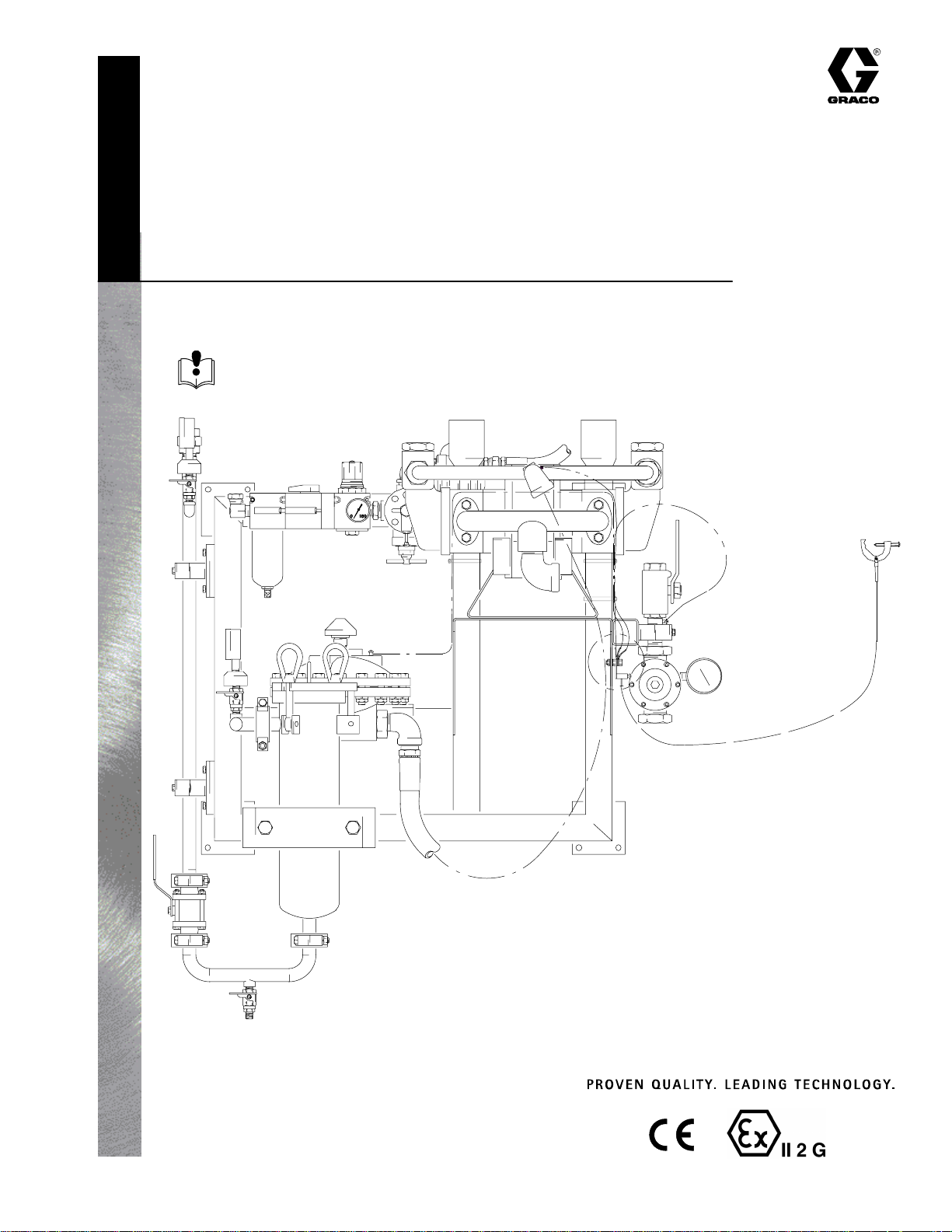
310564D
Model 96A637 Shown
307107 Fluid Regulator
307628 Fluid Ball Valves
307707 Surge Tanks
GRACO INC.ąP.O. BOX 1441ąMINNEAPOLIS, MNą55440-1441
Copyright 2002, Graco Inc. is registered to I.S. EN ISO 9001
TI0957
Related Manuals:
308169 Lubricators
308201 Runaway Valves
307843 Glutton Pumps
Page 2

Table of Contents
List of Models 2. . . . . . . . . . . . . . . . . . . . . . . . . . . . . . . . . .
Warnings 3. . . . . . . . . . . . . . . . . . . . . . . . . . . . . . . . . . . . . .
Component Identification 5. . . . . . . . . . . . . . . . . . . . . . . .
Setup 6. . . . . . . . . . . . . . . . . . . . . . . . . . . . . . . . . . . . . . . . .
Operation 10. . . . . . . . . . . . . . . . . . . . . . . . . . . . . . . . . . . .
Maintenance 13. . . . . . . . . . . . . . . . . . . . . . . . . . . . . . . . . .
List of Models
Model Pump
96A637 Glutton Right Hand Pump Mount
96A638 Glutton Left Hand Pump Mount
96A938 Glutton Right Hand Pump Mount
96A939 Glutton Left Hand Pump Mount
Description – Pump Model Ratio
Single Filter
Single Filter
Dual Filter
Dual Filter
Troubleshooting 15. . . . . . . . . . . . . . . . . . . . . . . . . . . . . . .
Parts 16. . . . . . . . . . . . . . . . . . . . . . . . . . . . . . . . . . . . . . . .
Technical Data 26. . . . . . . . . . . . . . . . . . . . . . . . . . . . . . . .
Dimensions 28. . . . . . . . . . . . . . . . . . . . . . . . . . . . . . . . . . .
Mounting Hole Layouts 29. . . . . . . . . . . . . . . . . . . . . . . . .
Graco Standard Warranty and Information 30. . . . . . . .
Maximum Fluid
Working Pressure
4:1 350 psi
(2.4 MPa, 24.5 bar)
4:1 350 psi
(2.4 MPa, 24.5 bar)
4:1 350 psi
(2.4 MPa, 24.5 bar)
4:1 350 psi
(2.4 MPa, 24.5 bar)
Maximum Pump
Air Input Pressure
90 psi
(0.6 MPa, 6.2 bar)
90 psi
(0.6 MPa, 6.2 bar)
90 psi
(0.6 MPa, 6.2 bar)
90 psi
(0.6 MPa, 6.2 bar)
Parts
Page
16
16
16
16
2 310564
Page 3
Symbols
Warning Symbol
WARNING
This symbol alerts you to the possibility of serious
injury or death if you do not follow the instructions.
WARNING
EQUIPMENT MISUSE HAZARD
Equipment misuse can cause the equipment to rupture or malfunction and result in serious injury.
INSTRUCTIONS
D This equipment is for professional use only.
D Read all instruction manuals, tags, and labels before operating the equipment.
D Use the equipment only for its intended purpose. If you are uncertain about usage, call your Graco
distributor.
D Do not alter or modify this equipment. Use only genuine Graco parts and accessories.
D Check equipment daily. Repair or replace worn or damaged parts immediately.
Caution Symbol
CAUTION
This symbol alerts you to the possibility of damage to
or destruction of equipment if you do not follow the
instructions.
D Do not exceed the maximum working pressure stated on the equipment or in the Technical Data
for your equipment. Do not exceed the maximum working pressure of the lowest rated component
in your system.
D Use fluids and solvents which are compatible with the equipment wetted parts. Refer to the Tech-
nical Data section of all equipment manuals. Read the fluid and solvent manufacturer’s warnings.
D Route hoses away from traffic areas, sharp edges, moving parts, and hot surfaces. Do not expose
Graco hoses to temperatures above 180_F (82_C) or below –40_F (–40_C).
D Wear hearing protection when operating this equipment.
D Do not lift pressurized equipment.
D Comply with all applicable local, state, and national fire, electrical, and safety regulations.
PRESSURIZED EQUIPMENT HAZARD
Spray from the gun, hose leaks, or ruptured components can splash fluid in the eyes or on the skin
and cause serious injury.
D Do not point the gun at anyone or at any part of the body.
D Do not stop or deflect leaks with your hand, body, glove or rag.
D Follow the Pressure Relief Procedure on page 10 whenever you: are instructed to relieve pres-
sure; stop spraying; clean, check, or service the equipment; and install or clean the spray tip.
D Tighten all fluid connections before operating the equipment.
D Check the hoses, tubes, and couplings daily. Replace worn, damaged, or loose parts immediately.
Permanently coupled hoses cannot be repaired; replace the entire hose.
310564 3
Page 4
WARNING
MOVING PARTS HAZARD
Moving parts, such as the air motor piston, can pinch or amputate your fingers.
D Keep clear of all moving parts when starting or operating the pump.
D Before servicing the equipment, follow the Pressure Relief Procedure on page 10 to prevent the
equipment from starting unexpectedly.
FIRE AND EXPLOSION HAZARD
Improper grounding, poor ventilation, open flames or sparks can cause a hazardous condition and
result in a fire or explosion and serious injury.
D Ground the equipment and the object being sprayed. Refer to Grounding on page 9.
D If there is any static sparking or you feel an electric shock while using this equipment, stop spray-
ing immediately. Do not use the equipment until you identify and correct the problem.
D Provide fresh air ventilation to avoid the buildup of flammable fumes from solvents or the fluid
being sprayed.
D Keep the spray area free of debris, including solvent, rags, and gasoline.
D Electrically disconnect all equipment in the spray area.
D Extinguish all open flames or pilot lights in the spray area.
D Do not smoke in the spray area.
D Do not turn on or off any light switch in the spray area while operating or if fumes are present.
D Do not operate a gasoline engine in the spray area.
TOXIC FLUID HAZARD
Hazardous fluid or toxic fumes can cause serious injury or death if splashed in the eyes or on the skin,
inhaled, or swallowed.
D Know the specific hazards of the fluid you are using.
D Store hazardous fluid in an approved container. Dispose of hazardous fluid according to all local,
state and national guidelines.
D Always wear protective eyewear, gloves, clothing and respirator as recommended by the fluid and
solvent manufacturer.
4 310564
Page 5
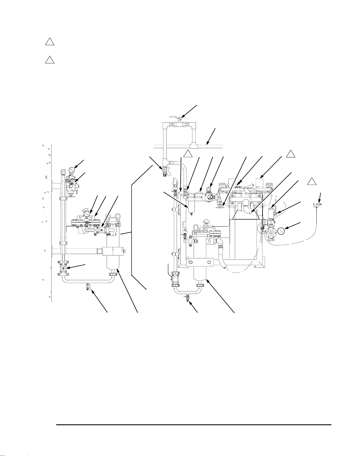
Component Identification
Ensure that there is 5 ft (1.5 m) overhead clearance
1
for a wall mounted system and at least 7 ft (2.1 m)
for a floor mounted system.
Mount the circulation package so the top of the
2
bracket is 5 to 6 ft (1.5 to 1.8 m) above the floor.
B
W
Z
G
Y
R S
2
K L M N
1
C
B
J
E
E
Side View
F Ref
KEY
A Pump Inlet
B Fluid Gauge and Dampener
C Fluid Gauge Ball Valve
D Fluid Filter
E Filter Ball Valve
F Fluid Drain Valve
G Air Supply Inlet
H Air Filter
H
D Ref
Model 96A637 Shown
J Fluid Surge Tank
K Air Motor Master Air Valve
L Air Regulator and Gauge
M Pump Runaway Control Valve
N Pump
P Ground Wire
R Wall Mount Frame
S Air Line Lubricator
A
T
TI0957
DF
T Fluid Return Inlet
U Fluid Return Valve
V Fluid Regulator and Gauge
W Bleed–type Master Air Valve
(not supplied)
Y Air Line Drain Valve
(not supplied)
Z Facility Air Supply
1
P
U
V
Fig. 1
310564 5
Page 6
Setup
WARNING
To reduce the risk of serious injury whenever you
are instructed to relieve pressure, always follow the
Pressure Relief Procedure on page 10.
Site Preparation
Fig. 1. Relieve system pressure. For installing any
one of the packages listed in this manual, select a site
with at least 5 ft (1.5 m) overhead clearance for the
wall mounted systems and at least 7 ft (2.1 m) for the
floor mounted systems.
Ensure that the wall is strong enough to support the
weight of the circulation package and accessories,
fluid, hoses, and stress caused during pump operation.
D The bleed-type master air valve (K) is required in
your system to relieve air trapped between it and
the air motor when the valve is closed (see the
preceding WARNING).
D The fluid drain valve (F), is mounted on the
bottom of the fluid filter bowl. The fluid drain valve
is required in your system to relieve fluid pressure
in the displacement pump, fluid filter, hose, and
gun. (see the preceding WARNING).
D The pump air filter (H) includes an air filter with a
40 micron polypropylene element, to remove harmful dirt and moisture from the compressed air
supply.
Ensure that you have an adequate compressed air
supply.
Bring an air supply line from the facility air supply (Z) to
the circulation package location. Be sure all air lines
are properly sized and pressure-rated for the system.
Use only electrically conductive hoses. The air hose
should have a 1/2 npt(m) thread.
Install a bleed-type shutoff valve (W) in the air line to
isolate the air line components for servicing. Install a
moisture trap and drain valve (Y) to help remove
moisture and contaminants from the compressed air
supply.
Keep the site clear of any obstacles or debris that
could interfere with the operator’s movement.
Have a grounded, metal pail available for use when
flushing the system.
Supplied Components
Refer to Fig. 1.
WARNING
A bleed-type master air valve (K) and a fluid drain
valve (F) are supplied. These components help
reduce the risk of serious injury, including splashing
of fluid in the eyes or on the skin, and injury from
moving parts if you are adjusting or repairing the
pump.
D The pump air regulator and gauge (L) controls
pump speed and outlet pressure by adjusting the
air pressure to the pump. The gauge provides a
readout of air pressure to the pump. See manual
308168 for further details.
D The pump runaway control valve (M) protects
the pump against damage by a runaway air motor.
See manual 308201 for further details.
D The air line lubricator (S) provides automatic
lubrication of the air motor.
D The pump (N), run by air motor, circulates fluid
throughout the system. See pump manual for
further details.
D Fluid is supplied to the pump through the fluid
outlet (A). Fluid pressure is monitored by the two
fluid gauges (B).
D The fluid filter (D) includes a 60 mesh (250 mi-
cron) stainless steel element to filter particles from
the fluid as it leaves the pump.
D The fluid surge tank (J) protects against surges in
the fluid lines during gun use and system operation.
The bleed-type master air valve relieves air trapped
between this valve and the pump after the air is
shut off. Trapped air can cause the pump to cycle
unexpectedly.
The fluid drain valve assists in relieving fluid pressure in the displacement pump, fluid filter, hose,
and gun. Triggering the gun to relieve pressure
may not be sufficient.
6 310564
D The fluid regulator and gauge (V) controls fluid
inlet pressure. The gauge provides a readout of
fluid pressure at the inlet. See manual 307107 for
further details.
D Fluid is returned from the circulation package to the
the system through the fluid return valve (U). See
valve manual 307628 for further details.
Page 7
Setup
WARNING
To reduce the risk of serious injury whenever you
are instructed to relieve pressure, always follow the
Pressure Relief Procedure on page 10.
Wall Mount installation of the Circulation
Package
Single or Dual Floor Mount installation of
the Circulation Package
Fig. 1. The circulation package consists of the pump
mounted on the wall mount frame. Also on the wall
mount frame are air filter, master air valve, air controls,
lubricator, surge tank, fluid filter, and plumbing.
Fig. 1. The circulation package consists of the pump
mounted on the wall mount frame. Also on the wall
mount frame are air filter, master air valve, air controls,
lubricator, surge tank, fluid filter, and plumbing.
NOTE: Ensure that there is 5 ft (1.5 m) overhead
clearance for a wall mounted system.
NOTE: Refer to Fig. 1, and to the Dimension drawing
on page 28 and the Mounting Hole Layout on page 29.
1. Relieve system pressure prior to installation of
circulation package. Follow Pressure Relief
Procedure on page 10.
2. Ensure that wall is strong enough to support
weight of circulation package, accessories, fluid
plumbing, and stress caused during pump operation.
3. Using capable hoist, position wall mount frame (R)
so that the top edge is 5 to 6 ft (1.5 to 1.8 m)
above floor. Check that wall mount frame is level.
Mark four holes on wall for each of four wall mount
feet.
4. Drill holes where marked on wall.
WARNING
NOTE: Ensure that there is 7 ft (2.1 m) overhead
clearance for a floor mounted system.
NOTE: Refer to Fig. 1, and to the Single Mount Floor
Stand drawing on page 24 or the Dual Mount Floor
Stand drawing on page 25. Also refer to the Mounting
Hole Layouts on page 29.
1. Relieve system pressure prior to installation of
circulation package. Follow Pressure Relief
Procedure on page 10.
2. Anchor either single or dual floor stand to floor
using 1/2 in. bolts.
WARNING
Do not attempt to mount two circulation packages
on a single mount floor stand. Use dual mount
stand for dual or back–to–back installations. Failure
to do so can result in mount failure causing equipment damage or personal injury
The wall mount frame (R) must be bolted to the
wall. Do not simply hang the wall mount frame.
Failure to do so may cause circulation package to
fall causing equipment damage or personal injury.
5. Using capable hoist, lift circulation package back
into position. Bolt wall mount frame (R) to wall.
Use 1/2 in. bolts and washers to mount circulation
package to wall. Use bolts that are long enough to
keep wall mount frame from vibrating during
operation.
3. Using capable hoist, position wall mount frame (R)
so that the top edge is level with the top edge of
the floor stand. For dual, use second hoist and
align with dual floor stand and first circulation
package.
4. Bolt single unit or dual units to floor stand using
3/8 in. hardware.
310564 7
Page 8
Setup
Connect the Fluid Lines
Fig. 1. Connect system fluid supply line to the circulation package at fluid supply inlet (A). Close filter ball
valves (E) to isolate the circulation package from the
main fluid supply line.
Connect circulation package to the system fluid return
line at fluid return outlet (T). Close fluid return valve (U)
to isolate the circulation package from the main fluid
return line.
Connect the Air Line
Fig. 1. Bring an air supply line from the facility air
supply (Z) to the circulation package location. Be sure
all air lines are properly sized and pressure-rated for
the system. Use only electrically conductive hoses. Air
hose should have a 1/2 npt(m) thread.
Install a bleed-type shutoff valve (W) in the air line to
isolate the air line components for servicing. Install a
moisture trap and drain valve (Y) to help remove
moisture and contaminants from the compressed air
supply.
Using the Quick Connectors
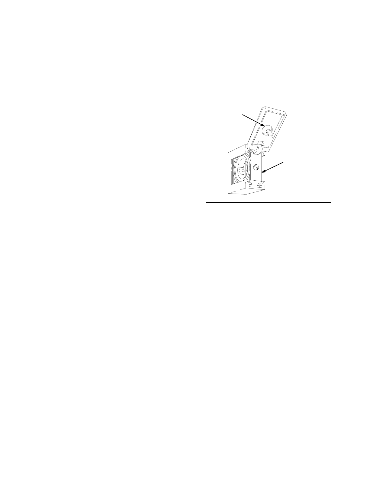
Fig. 2. To open a quick connector (A), loosen the
captive screw (B) and open the connector. Slide the
desired component into or out of the connector, close,
and tighten the screw.
B
A
06278
Fig. 2
8 310564
Page 9
Setup
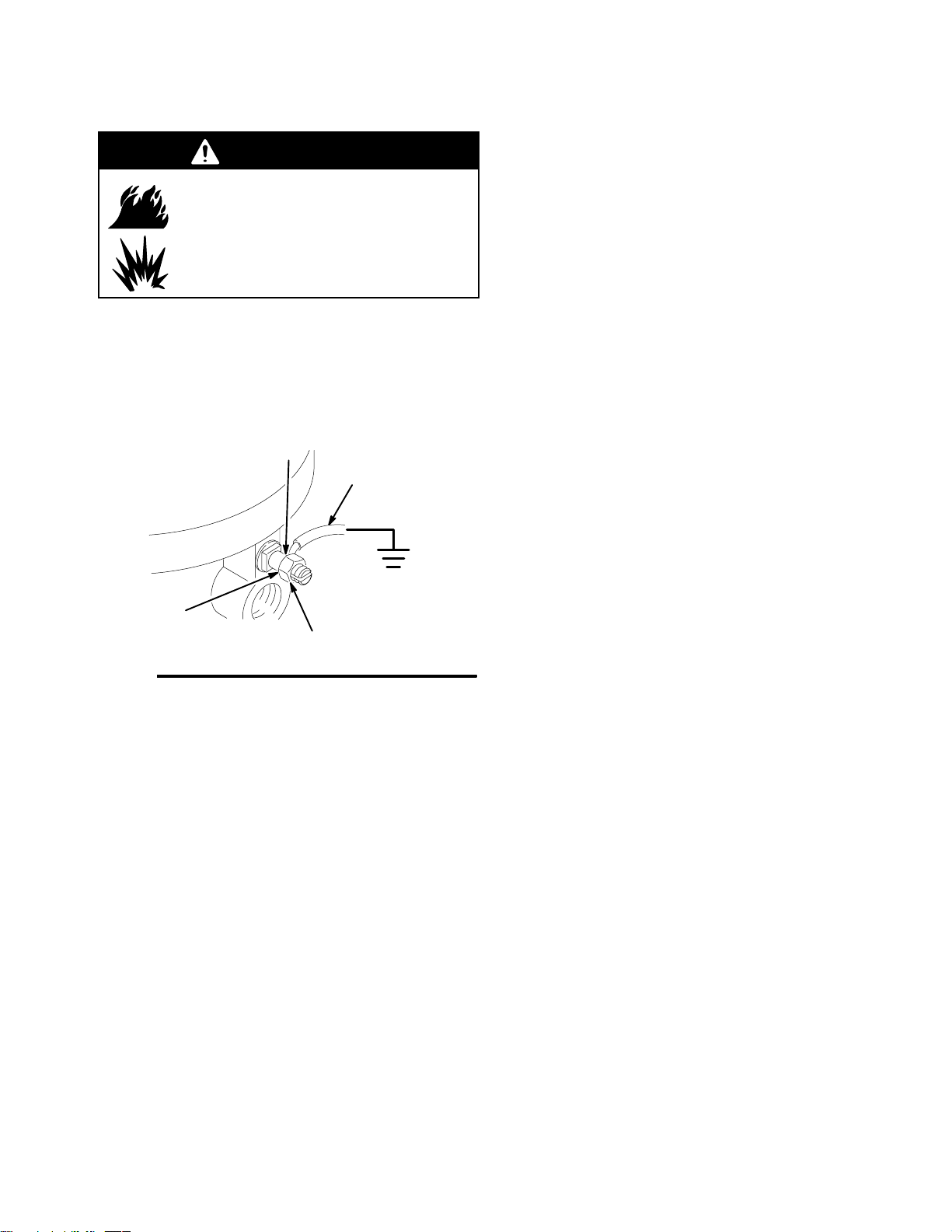
Grounding
WARNING
FIRE AND EXPLOSION HAZARD
Before operating the circulation package, ground the system as explained
below. Also read the section FIRE AND
EXPLOSION HAZARD on page 4.
1. Pump: use the ground wire and clamp (A, supplied). See Fig. 3. Loosen the grounding lug locknut (W) and washer (X). Insert one end of the
ground wire (A) into the slot in lug (Z) and tighten
the locknut securely. Connect the ground clamp to
a true earth ground.
Z
A
2. Air and fluid hoses: use only electrically conductive
hoses.
3. Air compressor: follow manufacturer’s recommendations.
4. Spray gun: ground through connection to a properly grounded fluid hose and pump.
5. Fluid supply container: follow your local code.
6. Object being sprayed: follow your local code.
7. Solvent pails used when flushing: follow your local
code. Use only metal pails, which are conductive,
placed on a grounded surface. Do not place the
pail on a nonconductive surface, such as paper or
cardboard, which interrupts the grounding continuity.
Fig. 3
X
W
0720
8. To maintain grounding continuity when flushing or
relieving pressure, hold a metal part of the spray
gun firmly to the side of a grounded metal pail,
then trigger the gun.
310564 9
Page 10

Operation
Pressure Relief Procedure
WARNING
PRESSURIZED EQUIPMENT HAZARD
The system pressure must be manually relieved to
prevent the system from starting or spraying accidentally. To reduce the risk of an injury from accidental spray from the gun, splashing fluid, or
moving parts, follow the Pressure Relief Proce-
dure whenever you:
D are instructed to relieve the pressure,
D stop spraying,
D check or service any of the system equipment,
D or install or clean the spray nozzle.
1. Fig. 4. Relieve the pressure of the entire system
following applicable system pressure relief procedures. Ensure that system pressure is relieved
before proceeding with step 2.
2. Close the bleed-type master air valve (W, required
in your system).
3. Trigger the gun at the last gun station to relieve
fluid pressure. Maintain firm metal-to-metal contact
between the gun and a grounded waste pail.
Repeat for all gun stations.
4. Open the fluid drain valve (14) to relieve fluid
pressure which may be trapped in the pump,
plumbing, or hose.
If you suspect that pressure is not fully relieved after
following the steps above, wrap a fitting near the pump
outlet with a rag, and slowly and carefully loosen the
fitting to relieve pressure. Be careful to protect your
eyes from splashing.
WARNING
To reduce the risk of serious injury whenever you
are instructed to relieve pressure, always follow the
Pressure Relief Procedure at left.
Flush the Circulation Package Before First
Use
The circulation package is tested with lightweight oil,
which is left in to protect the circulation package parts.
If the fluid you are using may be contaminated by the
oil, flush it out with a compatible solvent. See Flush-
ing on page 13.
10 310564
Page 11

Operation
W
Y
AA CC
BB
DD
Side View
14 Ref
23
5
23 Ref
Model 96A637 Shown
TI0957
14
Fig. 4
310564 11
Page 12

Operation
Starting and Adjusting the Pump
1. Fig. 4. Open all fluid shutoff valves (5–two). Make
sure Air Regulator (CC) is fully closed.
2. Open the spray gun at the last gun station and
keep it open while starting the pump.
3. Open the bleed-type master air valves (W, AA).
4. Slowly open air regulator (CC) until the pump
starts. The air regulator controls the pump speed
and fluid outlet pressure.
5. Adjust the fluid pressure to the lowest setting
necessary to get the desired results. Higher pressures may not improve the spray pattern and will
cause premature component wear. Use the air
regulator (CC) to adjust the pump speed and fluid
pressure until the spray is completely atomized.
6. To adjust the spray pattern, follow the complete
instructions in your gun manual.
WARNING
COMPONENT RUPTURE HAZARD
To reduce the risk of overpressurizing
your system, which could cause
component rupture and serious injury,
never exceed the specified maximum air input
pressure to the pump (see Technical Data on
page 26).
CAUTION
Do not allow the pump to run dry. It will quickly
accelerate to a high speed, causing damage. If your
pump is running too fast, stop it immediately and
check the fluid supply. If the container is empty and
air has been pumped into the lines, refill the container and prime the pump and the lines, or flush and
leave it filled with a compatible solvent. Eliminate all
air from the fluid system.
Shutdown
7. When you have achieved the desired spray pattern, release the gun trigger. The pump will continue to cycle as long as air is supplied.
8. One at a time, open any other guns in the system
to purge air from the lines.
NOTE: In a circulating system, the pump will continue
to cycle as long as air is supplied. In a direct supply
system, the pump starts when the gun is opened, and
stops when the gun is closed.
WARNING
To reduce the risk of serious injury whenever you
are instructed to relieve pressure, always follow the
Pressure Relief Procedure on page 10.
1. Relieve the pressure.
NOTE: If the system will remain inactive for an extended period, flush with a compatible solvent before
shutting down. See Flushing on page 13.
12 310564
Page 13

Maintenance
Preventive Maintenance Schedule
The operating conditions of your particular system
determine how often maintenance is required. Establish a preventive maintenance schedule by recording
when and what kind of maintenance is needed, and
then determine a regular schedule for checking your
system.
Flushing
WARNING
FIRE AND EXPLOSION HAZARD
Before flushing, read the section FIRE
AND EXPLOSION HAZARD on page
4. Be sure the entire system and flushing pails are properly grounded. Refer to
Grounding on page 9.
Fig. 4. Flush the pump:
D Before the first use
2. Remove the air cap and spray tip from the gun.
See the gun manual.
3. Fig. 4. Remove the filter element from the fluid
filter (23). Reinstall the filter bowl.
4. Hold a metal part of the gun firmly to the side of a
grounded metal pail.
5. Start the pump. Always use the lowest possible
fluid pressure when flushing.
6. Trigger the gun. Flush the system until clear
solvent flows from the gun.
7. Release the gun trigger and lock the trigger safety.
The pump will continue to cycle as long as air is
supplied.
8. Direct drain hose into a waste container. Continue
flushing until clear fluid comes from the hose.
9. Relieve the pressure.
10. Clean the air cap, spray tip, and fluid filter element
separately, then reinstall them.
D When changing colors or fluids
D Before fluid can dry or settle out in a dormant pump
(check the pot life of catalyzed fluids)
D Before storing the pump.
Flush with a fluid that is compatible with the fluid you
are pumping and with the wetted parts in your system.
Check with your fluid manufacturer or supplier for
recommended flushing fluids and flushing frequency.
WARNING
To reduce the risk of serious injury whenever you
are instructed to relieve pressure, always follow the
Pressure Relief Procedure on page 10.
1. Fig. 4. Relieve the pressure.
Fluid Filter Service
WARNING
To reduce the risk of serious injury whenever you
are instructed to relieve pressure, always follow the
Pressure Relief Procedure on page 10.
1. Fig. 4. Relieve the pressure.
2. Replace the fluid filter as required to maximize
filtering efficiency and to avoid excessive pressure
drop.
3. Close two filter ball valves (5). Open filter drain
valve (14) and partially loosen filter top to allow
fluid in filter to drain into waste container.
4. Install new filter, close filter drain valve (14) and
open filter ball valves (5).
310564 13
Page 14

Maintenance
Air Filter Service
1. Fig. 4. Every day, drain contaminants from the
bowl before reaching the baffle level by opening
the drain at the bottom of the bowl (BB).
WARNING
To reduce the risk of serious injury whenever you
are instructed to relieve pressure, always follow the
Pressure Relief Procedure on page 10.
2. Clean the air filter regularly to maximize filtering
efficiency and to avoid excessive pressure drop.
Fully relieve pressure to remove the bowl (BB).
3. Clean the filter element and bowl using household
soap and water or denatured alcohol. Use compressed air to blow out the filter body. Blow the
filter element out from the inside.
4. Clean the sight glass thoroughly. Do not leave
solvent residue in the sight glass as it may attack
or weaken the glass. If the sight glass appears
damaged, replace it immediately.
14 310564
Page 15

Troubleshooting
WARNING
To reduce the risk of serious injury whenever you are instructed to relieve pressure, always follow
the Pressure Relief Procedure (page 10).
For pump service see pump manual.
Problem Cause(s) Solution(s)
Pump output low on both strokes Restricted air or hydraulic lines Clear any obstructions; be sure all
valves are open; increase pressure.
Empty fluid supply Refill and reprime pump. In an air-pow-
ered system, use pump runaway valve.
Clogged fluid outlet line, valves, etc. Clear.
Worn packings Tighten packing nut; replace all pack-
ings. See pump manual.
Pump output low on only one stroke Worn pump seals Check and repair. See pump manual.
No output Improperly installed ball check valves Check and correct. See pump manual.
Pump operates erratically Exhausted fluid supply Refill and reprime pump. In an air-pow-
ered system, use pump runaway valve.
Worn pump seals Check and repair. See pump manual.
Pump does not operate Restricted air or hydraulic power sup-
ply lines
Exhausted fluid supply Refill and reprime pump.
Clogged fluid outlet line, valves, etc. Clear.
Fluid dried on piston rod Disassemble and clean pump. Stop
Clear any obstructions; be sure all shutoff valves are open; increase pressure.
pump at bottom of stroke. See pump
manual.
310564 15
Page 16

Right Hand Mount Model: 96A637
4:1 Ratio, Glutton Pump
50 Ref
49
51 Ref
46 Ref
44
47
4,3,2
Parts
1
37,38,39
32,33,34 30
7
13
11
15
16
13
17
14
4,3
48
43 Ref
Detail A
5
5,4,3
12,4,3
14
19
53,21,20
22
54
35
31
5225,26,27
51
TI0957
35 50
46
45
43
36
24
14
16 310564
Ref 5
233,414 Ref
42
10
Detail A
Page 17

Right Hand Mount Model: 96A637
4:1 Ratio, Glutton Pump
Parts
Ref Part
No. No. Description Qty
1 618216 FRAME, wall/floor stand mount 1
2 618217 MANIFOLD, surge tank discharge 1
3 51A297 CLAMP, sanitary, sst, 1–1/2” 6
4 516320 GASKET,1” tube 6
5 515563 BALL VALVE, paint service 2
7 155470 UNION, swivel, 90_ 1
8 101353 NIPPLE, pipe 1
10 516037 ELBOW, street, 90_, sst 1
11 515763 COUPLING, full, sst, 3/4” npt 1
12 51A795 FITTING 1
13 515571 GAUGE and DAMPENER, sst 2
14 237528 BALL VALVE, sst, 1/4” npt 3
See 307628 for parts
15 516010 FITTING, elbow, 90_ 1
16 516771 FITTING, nipple, pipe 1
17 220157 TANK, surge, sst 1
See 307707 for parts
19 618236 BRACKET, tube support, 1” 2
20 100022 SCREW, cap, hex hd 4
21 100016 WASHER, lock 4
22 618806 HEADER, filter discharge 1
23 916366 FILTER 1
24 618218 MANIFOLD, filter, discharge 1
25 917089 KIT, accessory 1
See 308168 and 308201 for parts
26 C19818 SCREW, cap, soc hd 2
Ref Part
No. No. Description Qty
27 105510 WASHER, lock, spring (hi–collar) 2
30 521778 HOSE, air 1
31 237011 PUMP, 4:1 Glutton, sst 1
32 100004 SCREW, cap, hex hd 4
33 100133 WASHER, lock 4
34 100307 NUT, hex, 3/8” 4
35 504045 FITTING, elbow, street 2
36 241207 KIT, repair, valve 1
37 101044 WASHER, plain 4
38 194255 SPACER, accumulator 2
39 551292 SCREW, cap, hex hd 2
42 515602 HOSE, paint, PTFE 1
43 220011 GROUND WIRE ASSY, 25 ft 1
44 101896 TERMINAL, ring 4
45 112278 WRAP, tie, electrical 4
46 236297 CLAMP ASSY, grounding 1
47 115248 SCREW, cap, hex hd 1
48 100127 NUT, full, hex 2
49 100718 WASHER 2
50 220089 CONDUCTOR, ground 1
51 065136 WIRE, copper, electrical 1
52 101754 PLUG, pipe 1
53 110755 WASHER, plain 1
54 515992 FITTING, bushing, reducer 1
See 307843 for parts
310564 17
Page 18

Left Hand Mount Model: 96A638
4:1 Ratio, Glutton Pump
Parts
31
46
45
43
7
3550
32,33,3430
51
37,38,39
52 25,26,27
1
2,3,4
3,4,5
3,4,12
14
19
20,21,53
22
46 Ref
44
47
51 Ref
50 Ref
49
48
43 Ref
Detail A
13
11
15
16
13
17
14
36
Detail A
10
42
23 3,4 14 Ref
54
54
35
5 Ref
5
3,4
24
14
TI0958
18 310564
Page 19

Left Hand Mount Model: 96A638
4:1 Ratio, Glutton Pump
Parts
Ref Part
No. No. Description Qty
1 618216 FRAME, wall/floor stand mount 1
2 618217 MANIFOLD, surge tank discharge 1
3 51A297 CLAMP, sanitary, sst, 1–1/2” 6
4 516320 GASKET,1” tube 6
5 515563 BALL VALVE, paint service 2
7 155470 UNION, swivel, 90_ 1
8 101353 NIPPLE, pipe 1
10 516037 ELBOW, street, 90_, sst 1
11 515763 COUPLING, full, sst, 3/4” npt 1
12 51A795 FITTING 1
13 515571 GAUGE and DAMPENER, sst 2
14 237528 BALL VALVE, sst, 1/4” npt 3
See 307628 for parts
15 516010 FITTING, elbow, 90_ 1
16 516771 FITTING, nipple, pipe 1
17 220157 TANK, surge, sst 1
See 307707 for parts
19 618236 BRACKET, tube support, 1” 2
20 100022 SCREW, cap, hex hd 4
21 100016 WASHER, lock 4
22 618806 HEADER, filter discharge 1
23 916366 FILTER 1
24 618218 MANIFOLD, filter, discharge 1
25 917090 KIT, accessory 1
See 308168 and 308201 for parts
26 C19817 SCREW, cap, soc hd 2
Ref Part
No. No. Description Qty
27 105510 WASHER, lock, spring (hi–collar) 2
30 521778 HOSE, air 1
31 237011 PUMP, 4:1 Glutton, sst 1
32 100004 SCREW, cap, hex hd 4
33 100133 WASHER, lock 4
34 100307 NUT, hex, 3/8” 4
35 504045 FITTING, elbow, street 2
36 241207 KIT, repair, valve 1
37 101044 WASHER, plain 4
38 194255 SPACER, accumulator 2
39 551292 SCREW, cap, hex hd 2
42 515602 HOSE, paint, PTFE 1
43 220011 GROUND WIRE ASSY, 25 ft 1
44 101896 TERMINAL, ring 4
45 112278 WRAP, tie, electrical 4
46 236297 CLAMP ASSY, grounding 1
47 115248 SCREW, cap, hex hd 1
48 100166 NUT, full, hex 2
49 100718 WASHER 2
50 220089 CONDUCTOR, ground 1
51 065136 WIRE, copper, electrical 1
52 101754 PLUG, pipe 1
53 110755 WASHER, plain 1
54 515992 FITTING, bushing, reducer 1
See 307843 for parts
310564 19
Page 20

Parts
Right Hand Mount Dual Filter Model: 96A938
4:1 Ratio, Glutton Pump
13
11
15
16
30
13
17
14
49
48
50 Ref
Detail A
51 Ref
46 Ref
43 Ref
44
47
4,3,2
5,4,3
12,4,3
53,21,20
14
19
1
37,38,39
5225,26,27
32,33,34
51
7
31
35 50
46
45
43
24
4,3
14
22
5
54
35
Ref 5
233,414 Ref
TI0959
42 10
Detail A
36
20 310564
Page 21

Parts
Right Hand Mount Dual Filter Model: 96A938
4:1 Ratio, Glutton Pump
Ref Part
No. No. Description Qty
1 618380 FRAME, wall/floor stand mount, rh 1
2 618217 MANIFOLD, surge tank discharge 1
3 51A297 CLAMP, sanitary, sst, 1–1/2” 6
4 516320 GASKET,1” tube 6
5 515563 BALL VALVE, paint service 2
7 155470 UNION, swivel, 90_ 1
8 101353 NIPPLE, pipe 1
10 516037 ELBOW, street, 90_, sst 1
11 515763 COUPLING, full, sst, 3/4” npt 1
12 51A795 FITTING 1
13 515571 GAUGE and DAMPENER, sst 2
14 237528 BALL VALVE, sst, 1/4” npt 3
See 307628 for parts
15 516010 FITTING, elbow, 90_ 1
16 516771 FITTING, nipple, pipe 1
17 220157 TANK, surge, sst 1
See 307707 for parts
19 618236 BRACKET, tube support, 1” 2
20 100022 SCREW, cap, hex hd 4
21 100016 WASHER, lock 4
22 618806 HEADER, filter discharge 1
23 917091 FILTER, dual assembly 1
24 618218 MANIFOLD, filter, discharge 1
25 917089 KIT, accessory 1
See 308168 and 308201 for parts
26 C19818 SCREW, cap, soc hd 2
Ref Part
No. No. Description Qty
27 105510 WASHER, lock, spring (hi–collar) 2
30 521778 HOSE, air 1
31 237011 PUMP, 4:1 Glutton, sst 1
32 100004 SCREW, cap, hex hd 4
33 100133 WASHER, lock 4
34 100307 NUT, hex, 3/8” 4
35 504045 FITTING, elbow, street 2
36 241207 KIT, repair, valve 1
37 101044 WASHER, plain 4
38 194255 SPACER, accumulator 2
39 551292 SCREW, cap, hex hd 2
42 515602 HOSE, paint, PTFE 1
43 220011 GROUND WIRE ASSY, 25 ft 1
44 101896 TERMINAL, ring 4
45 112278 WRAP, tie, electrical 4
46 236297 CLAMP ASSY, grounding 1
47 115248 SCREW, cap, hex hd 1
48 100166 NUT, full, hex 2
49 100718 WASHER 2
50 220089 CONDUCTOR, ground 1
51 065136 WIRE, copper, electrical 1
52 101754 PLUG, pipe 1
53 110755 WASHER, plain 1
54 515992 FITTING, bushing, reducer 1
See 307843 for parts
310564 21
Page 22

Parts
Left Hand Mount Dual Filter Model: 96A939
4:1 Ratio, Glutton Pump
31
46
45
43
7
32,33,34 30
3550
51
37,38,39
52 25,26,27
1
2,3,4
3,4,5
3,4,12
14
19
20,21,53
22
46 Ref
44
47
51 Ref
50 Ref
49
48
43 Ref
Detail A
13
11
15
16
13
17
14
36
Detail A
22 310564
4210
TI0960
23 3,4 14 Ref
54
35
5 Ref
24
5
3,4
14
Page 23

Parts
Left Hand Mount Dual Filter Model: 96A939
4:1 Ratio, Glutton Pump
Ref Part
No. No. Description Qty
1 618381 FRAME, wall/floor stand mount, lh 1
2 618217 MANIFOLD, surge tank discharge 1
3 51A297 CLAMP, sanitary, sst, 1–1/2” 6
4 516320 GASKET,1” tube 6
5 515563 BALL VALVE, paint service 2
7 155470 UNION, swivel, 90_ 1
8 101353 NIPPLE, pipe 1
10 516037 ELBOW, street, 90_, sst 1
11 515763 COUPLING, full, sst, 3/4” npt 1
12 51A795 FITTING 1
13 515571 GAUGE and DAMPENER, sst 2
14 237528 BALL VALVE, sst, 1/4” npt 3
See 307628 for parts
15 516010 FITTING, elbow, 90_ 1
16 516771 FITTING, nipple, pipe 1
17 220157 TANK, surge, sst 1
See 307707 for parts
19 618236 BRACKET, tube support, 1” 2
20 100022 SCREW, cap, hex hd 4
21 100016 WASHER, lock 4
22 618806 HEADER, filter discharge 1
23 917092 FILTER, dual assembly 1
24 618218 MANIFOLD, filter, discharge 1
25 917090 KIT, accessory 1
See 308168 and 308201 for parts
26 C19818 SCREW, cap, soc hd 2
Ref Part
No. No. Description Qty
27 105510 WASHER, lock, spring (hi–collar) 2
30 521778 HOSE, air 1
31 237011 PUMP, 4:1 Glutton, sst 1
32 100004 SCREW, cap, hex hd 4
33 100133 WASHER, lock 4
34 100307 NUT, hex, 3/8” 4
35 504045 FITTING, elbow, street 2
36 241207 KIT, repair, valve 1
37 101044 WASHER, plain 4
38 194255 SPACER, accumulator 2
39 551292 SCREW, cap, hex hd 2
42 515602 HOSE, paint, PTFE 1
43 220011 GROUND WIRE ASSY, 25 ft 1
44 101896 TERMINAL, ring 4
45 112278 WRAP, tie, electrical 4
46 236297 CLAMP ASSY, grounding 1
47 115248 SCREW, cap, hex hd 1
48 100166 NUT, full, hex 2
49 100718 WASHER 2
50 220089 CONDUCTOR, ground 1
51 065136 WIRE, copper, electrical 1
52 101754 PLUG, pipe 1
53 110755 WASHER, plain 1
54 515992 FITTING, bushing, reducer 1
See 307843 for parts
310564 23
Page 24

Single Mount Floor Stand, Model 618613
9/16 in. (4) places
Parts
24 310564
3/8 in. (8) places
TI0999
Model 618613
Page 25

Dual Mount Floor Stand, Model 618314
9/16 in. (4) places
Parts
3/8 in. (8) places
TI1000
Model 618314
310564 25
Page 26

Technical Data
4:1 Ratio Glutton Pumps
Category Data
Maximum Fluid Working Pressure 2.4 MPa, 24.5 bar (350 psi)
Air Operating Range 0.17–0.6 MPa, 1.7 – 6.2 bar (25 – 90 psi)
Fluid Flow at 60 Cycles per Minute 21.2 liter/min (5.6 gpm)
Cycles Per Liter (gallon) 2.7 (10.4)
Maximum Recommended Pump
Speed
Wetted parts Stainless Steel, PTFE, Ultra High Molecular Weight Polyethylene,
Vitonr is a registered trademark of the Du Pont Co.
60 cycles per minute
polypropylene, Nylon
Performance Chart
20 40 600 CPM
AIR FLOW
SCFM m3/min
60
1.68
FLUID OUTLET
PRESSURE
Bar PSI
28
400
21
300
14
200
7
100
0
0
012345678
KEY: Fluid Outlet Pressure: black curves
Air Consumption: gray curves
A at 100 psi (0.7 MPa, 7 bar) air pressure
B at 70 psi (0.48 MPa, 4.9 bar) air pressure
C at 40 psi (0.28 MPa, 2.8 bar) air pressure
A
B
C
3.75 11.25 18.75 26.25
FLUID FLOW
A
50 1.40
40
30
1.12
0.84
B
C
20
0.56
10
0.28
0
0
GPM
l / min0 7.5 15 22.5 30
To find outlet pressure (psi/MPa/bar) at a specific delivery
(GPM, lpm) and operating air pressure (psi/MPa/bar):
1. Locate desired delivery along bottom of chart.
2. Read vertical line up to intersection with selected fluid
outlet pressure curve. Follow left to scale and read outlet
pressure.
26 310564
To find pump air consumption (CFM, m3/min) specific
delivery (GPM, lpm) and operating air pressure (psi/MPa/
bar):
1. Locate desired delivery along bottom of chart.
2. Read vertical line up to intersection with selected air consumption curve. Follow right to scale and read air consumption.
Page 27

Notes
310564 27
Page 28

Ensure that there is 5 ft (1.5 m) overhead clearance
1
for wall mounted systems and at least 7 ft (2.1 m) for
floor mounted systems.
Mount the circulation package so the top of the
2
bracket is 5 to 6 ft (1.5 to 1.8 m) above the floor.
Dimensions
1
TI0957
2
Model 96A637 Shown
28 310564
Page 29

Mounting Hole Layout
1
Check that the wall frame is level before bolting it to the wall.
2
Mount the wall frame so the top edge is 5 to 6 ft (1.5 to 1.8 m) above the floor.
2
1
27.0 in.
(685.8 mm)
3/8 in. (8) places
31.0 in.
(787.4 mm)
Wall Frame 618313
25.0 in.
(635.0 mm)
0.5 in.
(12.7 mm)
3.0 in.
(76.2 mm)
310564 29
Page 30

Graco Standard Warranty
Graco warrants all equipment manufactured by Graco and bearing its name to be free from defects in material and workmanship on the
date of sale to the original purchaser for use. With the exception of any special, extended, or limited warranty published by Graco,
Graco will, for a period of twelve months from the date of sale, repair or replace any part of the equipment determined by Graco to be
defective. This warranty applies only when the equipment is installed, operated and maintained in accordance with Graco’s written
recommendations.
This warranty does not cover, and Graco shall not be liable for general wear and tear, or any malfunction, damage or wear caused by
faulty installation, misapplication, abrasion, corrosion, inadequate or improper maintenance, negligence, accident, tampering, or substitution of non–Graco component parts. Nor shall Graco be liable for malfunction, damage or wear caused by the incompatibility of
Graco equipment with structures, accessories, equipment or materials not supplied by Graco, or the improper design, manufacture,
installation, operation or maintenance of structures, accessories, equipment or materials not supplied by Graco.
This warranty is conditioned upon the prepaid return of the equipment claimed to be defective to an authorized Graco distributor for
verification of the claimed defect. If the claimed defect is verified, Graco will repair or replace free of charge any defective parts. The
equipment will be returned to the original purchaser transportation prepaid. If inspection of the equipment does not disclose any defect
in material or workmanship, repairs will be made at a reasonable charge, which charges may include the costs of parts, labor, and
transportation.
THIS WARRANTY IS EXCLUSIVE, AND IS IN LIEU OF ANY OTHER WARRANTIES, EXPRESS OR IMPLIED, INCLUDING BUT
NOT LIMITED TO WARRANTY OF MERCHANTABILITY OR WARRANTY OF FITNESS FOR A PARTICULAR PURPOSE.
Graco’s sole obligation and buyer’s sole remedy for any breach of warranty shall be as set forth above. The buyer agrees that no other
remedy (including, but not limited to, incidental or consequential damages for lost profits, lost sales, injury to person or property, or any
other incidental or consequential loss) shall be available. Any action for breach of warranty must be brought within two (2) years of the
date of sale.
Graco makes no warranty, and disclaims all implied warranties of merchantability and fitness for a particular purpose in connection
with accessories, equipment, materials or components sold but not manufactured by Graco. These items sold, but not manufactured
by Graco (such as electric motors, switches, hose, etc.), are subject to the warranty, if any, of their manufacturer. Graco will provide
purchaser with reasonable assistance in making any claim for breach of these warranties.
In no event will Graco be liable for indirect, incidental, special or consequential damages resulting from Graco supplying equipment
hereunder, or the furnishing, performance, or use of any products or other goods sold hereto, whether due to a breach of contract,
breach of warranty, the negligence of Graco, or otherwise.
FOR GRACO CANADA CUSTOMERS
The parties acknowledge that they have required that the present document, as well as all documents, notices and legal proceedings
entered into, given or instituted pursuant hereto or relating directly or indirectly hereto, be drawn up in English. Les parties reconnaissent avoir convenu que la rédaction du présente document sera en Anglais, ainsi que tous documents, avis et procédures judiciaires
exécutés, donnés ou intentés à la suite de ou en rapport, directement ou indirectement, avec les procedures concernées.
Graco Information
TO PLACE AN ORDER, contact your Graco distributor, or call one of the following numbers
to identify the distributor closest to you:
1–800–328–0211 Toll Free
612–623–6921
612–378–3505 Fax
All written and visual data contained in this document reflects the latest product information available at the time of publication.
Graco reserves the right to make changes at any time without notice.
International Offices: Belgium, China, Japan, Korea
Graco Headquarters: Minneapolis
www.graco.com
PRINTED IN USA 310564 03/2001, Revised 01/2005
30 310564
 Loading...