

Page 1
Instructions–Parts List
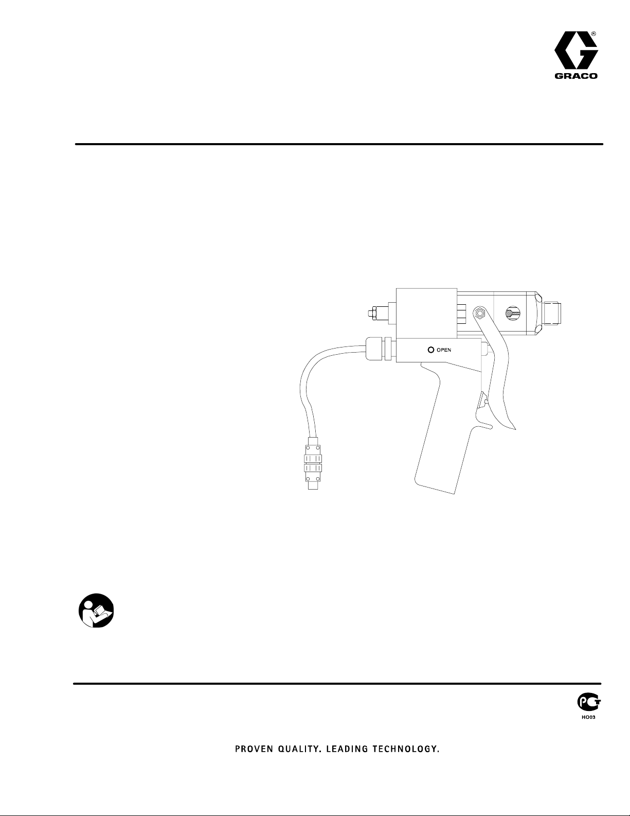
AIR OPERATED, SINGLE COMPONENT DISPENSE VALVE
1K Ultra–Litet
For dispensing a wide variety of single component sealants and adhesives.
4000 psi (28 MPa, 276 bar) Maximum Fluid Working Pressure
120 psi (0.84 MPa, 8.4 bar) Maximum Air Inlet Pressure
See page 2 for Table of Contents
Part No. 965766
Stainless Steel Wetted Parts, Machine
Mount Valve
Part No. 965767
Aluminum Wetted Parts, Hand–held
Valve with internal air switch
Part No. 965768
Aluminum Wetted Parts, Hand–held
Valve with electric switch for remote
operation
Part No. 965786
Aluminum Wetted Parts, Automatic
Machine Mount Valve
308876K
Part No. 243482
Stainless Steel Wetted Parts,
Precision Swirl Orbiter Mounted with
Nozzle Accessory
Part No. 243666
Stainless Steel Wetted Parts,
PrecisionFloR Control Valve
Machine Mount Valve
Important Safety Instructions
Read all warnings and instructions in this manual.
Save these instructions.
8370A
Model 965768 shown
Page 2
Table of Contents
Symbols
Warnings 2. . . . . . . . . . . . . . . . . . . . . . . . . . . . . . . . . . . . . .
Features 5. . . . . . . . . . . . . . . . . . . . . . . . . . . . . . . . . . . . . .
Installation 6. . . . . . . . . . . . . . . . . . . . . . . . . . . . . . . . . . . . .
Operation/Maintenance 8. . . . . . . . . . . . . . . . . . . . . . . . .
Troubleshooting 10. . . . . . . . . . . . . . . . . . . . . . . . . . . . . . .
Service 11. . . . . . . . . . . . . . . . . . . . . . . . . . . . . . . . . . . . . .
Parts 16. . . . . . . . . . . . . . . . . . . . . . . . . . . . . . . . . . . . . . . .
Accessories 25. . . . . . . . . . . . . . . . . . . . . . . . . . . . . . . . . .
Technical Data 27. . . . . . . . . . . . . . . . . . . . . . . . . . . . . . . .
Dimensions 28. . . . . . . . . . . . . . . . . . . . . . . . . . . . . . . . . . .
Graco Standard Warranty 30. . . . . . . . . . . . . . . . . . . . . .
Graco Information 30. . . . . . . . . . . . . . . . . . . . . . . . . . . . .
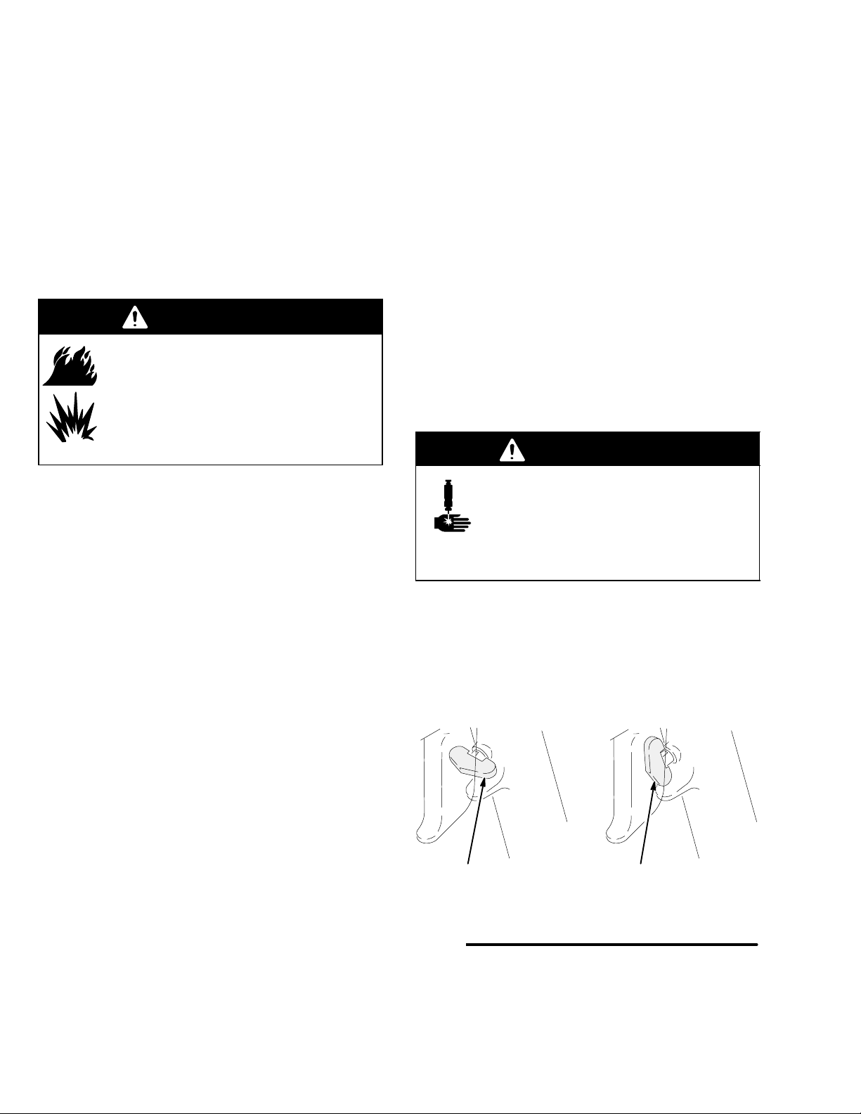
WARNING
SKIN INJECTION HAZARD
Spray from the valve, hose leaks, or ruptured components can inject fluid into your body and cause
extremely serious injury, including the need for amputation. Fluid splashed in the eyes or on the skin
can also cause serious injury.
Warning Symbol
WARNING
This symbol alerts you to the possibility of serious
injury or death if you do not follow the instructions.
Caution Symbol
CAUTION
This symbol alerts you to the possibility of damage to
or destruction of equipment if you do not follow the
instructions.
D Fluid injected into the skin might look like just a cut, but it is a serious injury. Get immediate surgi-
cal treatment.
D Do not point the valve at anyone or at any part of the body.
D Do not stop or deflect leaks with your hand, body, glove or rag.
D Be sure the valve trigger safety operates before dispensing.
D Lock the valve trigger safety when you stop dispensing.
D If the nozzle clogs while dispensing, fully release the trigger immediately.
D Follow the Pressure Relief Procedure on page 8 whenever you: are instructed to relieve pres-
sure; stop dispensing; clean, check, or service the equipment; and install or clean the nozzle.
D Tighten all fluid connections before operating the equipment.
D Check the hoses, tubes, and couplings daily. Replace worn, damaged, or loose parts immediately.
Permanently coupled hoses cannot be repaired; replace the entire hose.
D Use only Graco approved hoses. Do not remove any spring guard that is used to help protect the
hose from rupture caused by kinks or bends near the couplings.
2 308876
Page 3

INSTRUCTIONS
WARNING
EQUIPMENT MISUSE HAZARD
Equipment misuse can cause the equipment to rupture or malfunction and result in serious injury.
D This equipment is for professional use only.
D Read all instruction manuals, tags, and labels before operating the equipment.
D Use the equipment only for its intended purpose. If you are uncertain about usage, call your Graco
distributor.
D Do not alter or modify this equipment. Use only genuine Graco parts and accessories.
D Check equipment daily. Repair or replace worn or damaged parts immediately.
D Do not exceed the maximum working pressure stated on the equipment or in the Technical Data
for your equipment. Do not exceed the maximum working pressure of the lowest rated component
in your system.
D Use fluids and solvents which are compatible with the equipment wetted parts. Refer to the Tech-
nical Data section of all equipment manuals. Read the fluid and solvent manufacturer’s warnings.
D Do not use hoses to pull equipment.
D Route hoses away from traffic areas, sharp edges, moving parts, and hot surfaces. Do not expose
Graco hoses to temperatures above 180_F (82_C) or below –40_F (–40_C).
D Comply with all applicable local, state, and national fire, electrical, and safety regulations.
D Never use 1,1,1-trichloroethane, methylene chloride, other halogenated hydrocarbon solvents or
fluids containing such solvents in this equipment. Such use could result in a serious chemical
reaction, with the possibility of explosion, which could cause death, serious injury, and/or substantial property damage.
3308876
Page 4
WARNING
FIRE AND EXPLOSION HAZARD
Improper grounding, poor ventilation, open flames or sparks can cause a hazardous condition and
result in a fire or explosion and serious injury.
D Ground the equipment and the object being sprayed. Refer to Grounding on page 6.
D If there is any static sparking or you feel an electric shock while using this equipment, stop dis-
pensing immediately. Do not use the equipment until you identify and correct the problem.
D Provide fresh air ventilation to avoid the buildup of flammable fumes from solvents or the fluid
being dispensed.
D Keep the dispense area free of debris, including solvent, rags, and gasoline.
D Extinguish all open flames or pilot lights in the dispense area.
D Do not smoke in the dispense area.
D Do not turn on or off any light switch in the dispense area while operating or if fumes are present.
D Do not operate a gasoline engine in the dispense area.
TOXIC FLUID HAZARD
Hazardous fluid or toxic fumes can cause serious injury or death if splashed in the eyes or on the skin,
inhaled, or swallowed.
D Know the specific hazards of the fluid you are using.
D Store hazardous fluid in an approved container. Dispose of hazardous fluid according to all local,
state and national guidelines.
D Always wear protective eyewear, gloves, clothing and respirator as recommended by the fluid and
solvent manufacturer.
4 308876
Page 5
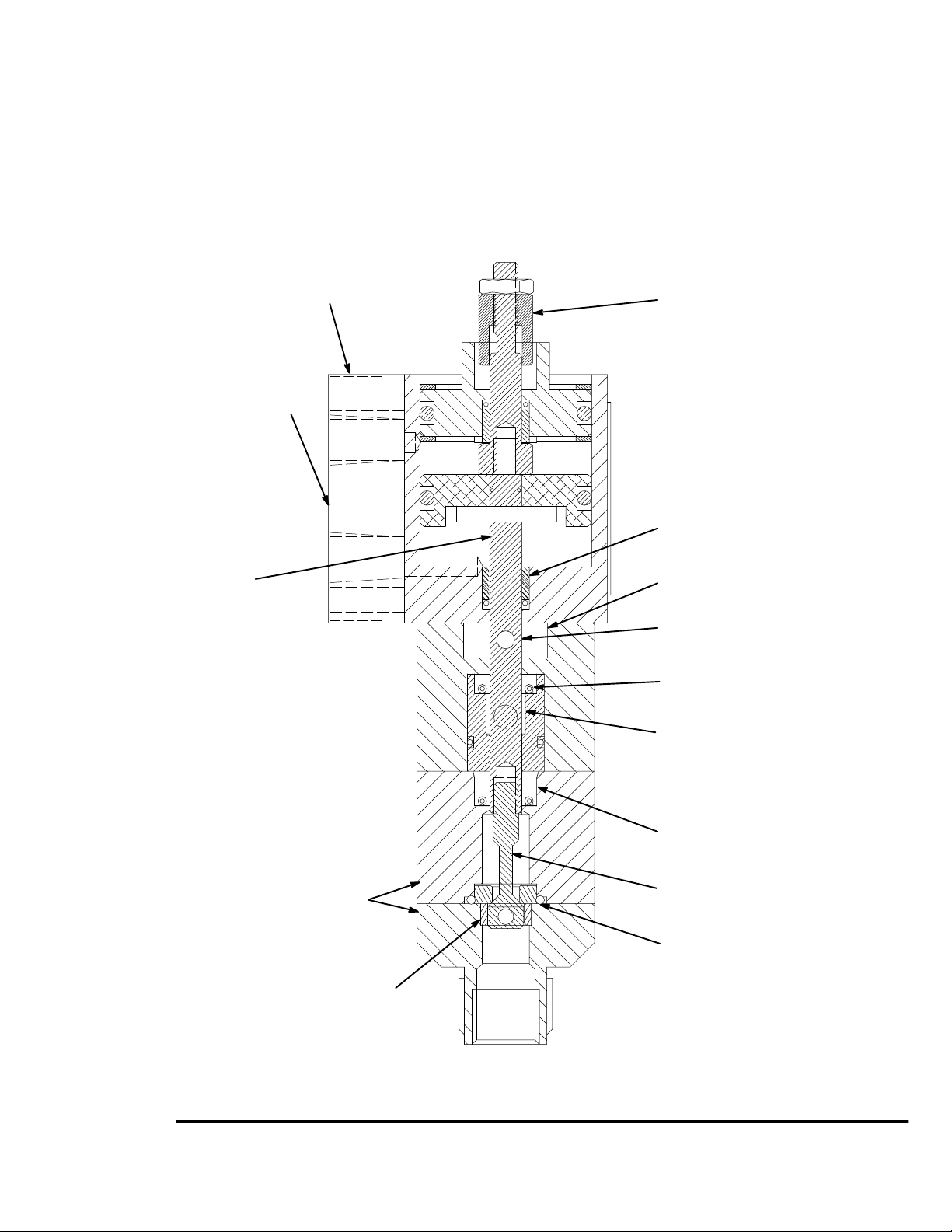
Features
A
D Adjustable forward travel to reduce material surge when
valve opens
D Severe-Dutyt needle and seat for longer operating life
D Lubricated packings for longer seal life
D Lightweight construction reduces operator/machinery
fatigue
4 Control Configurations
1. 1/8 npt(f) ported manifold block
2. Direct solenoid mount with speed control
3. Handle kit with 4-way air valve
4. Handle kit with electric switch
Accessory flow control fittings
to adjust open/close speed.
D Compact size for small X–Y tables, working areas, and
robots
D Handle kit provides easy conversion from automatic to
manual usage
D Stainless steel housing to handle most materials
Travel adjustment (Model 965766,
965767, 965768, and 965786 only)
Replaceable nylon bearings
Shaft is free to align
Aluminum or stainless wetted housings
Snuff back restrictor ring (13) is removable
for high flow applications.
Divorced air section
Hard chrome/stainless steel shaft
Urethane u-cup secondary seals
Self centering plastic bearing
Proven primary seals
Hardened stainless steel needles
Reversible carbide seat for severe duty
Fig. 1
8374B
8374
5308876
Page 6
Installation
A
NOTES:
D Reference numbers and letters in parentheses in
the text refer to the callouts in the figures and
drawings.
D Accessories are available from your Graco
representative. If you supply your own accessories,
be sure they are adequately sized and
pressure-rated to meet the system’s requirements.
Grounding
WARNING
FIRE AND EXPLOSION HAZARD
To reduce the risk of fire, explosion, and
serious injury, proper electrical grounding of every part of your system is essential. Read the warning section Fire
and Explosion Hazard on page 4, and
follow the grounding instructions below.
The following grounding instructions are minimum
requirements for a basic dispensing system. Your
system may include other equipment or objects which
must be grounded. Check your local electrical code for
detailed grounding instructions for your area and type
of equipment. Your system must be connected to a
true-earth ground.
D Pump: ground the pump by connecting ground wire
and clamp as described in your separate pump
instruction manual.
D Fluid supply container: ground according to your
local code.
D Flammable liquids in the spray area: must be in
approved, grounded containers. Do not store more
than the quantity needed for one shift.
D All solvent pails used when flushing: ground
according to local code. Use only metal pails, which
are conductive. Do not place the pail on a
non-conductive surface, such as paper or
cardboard, which interrupts the grounding
continuity.
D To maintain grounding continuity when flushing or
relieving pressure, hold a metal part of the valve
firmly to the side of a grounded metal pail, then
trigger the valve.
How to Use the Valve Trigger Safety
WARNING
SKIN INJECTION HAZARD
To prevent accidental triggering of the
gun and reduce the risk of a serious inju-
ry, including fluid injection or splashing in
the eyes or on the skin, lock the gun trigger safety
when you stop dispensing.
1. If you are using one of the hand-held versions of
the valve, lock the valve trigger safety by turning
the latch to a right angle with the gun body. See
Fig. 2.
D Air compressors and hydraulic power supplies:
ground the equipment according to the
manufacturer’s recommendations.
D Fluid hoses: use only grounded fluid hoses with a
maximum of 500 feet (150 m) combined hose
length to ensure grounding continuity. Check the
electrical resistance of your fluid hoses at least
once a week. If your hose does not have a tag on it
which specifies the maximum electrical resistance,
contact the hose supplier or manufacturer for the
maximum electrical resistance limits, replace the
hose immediately.
D Dispensing valve: ground the valve by connecting it
to a properly grounded fluid hose and pump.
6 308876
2. To unlock the valve trigger safety, push the latch
out and turn it parallel with the gun body.
Locked Unlocked
Fig. 2
8459
Page 7
Installation
Connections
D The fluid inlet is 1/4 npt(f).
D The fluid outlet is 1/4 npt(f) or 3/4–16 unf(m).
D Air inlets are 1/8 npt(f).
D See Accessories, page 25, to order air control
valves and tubing.
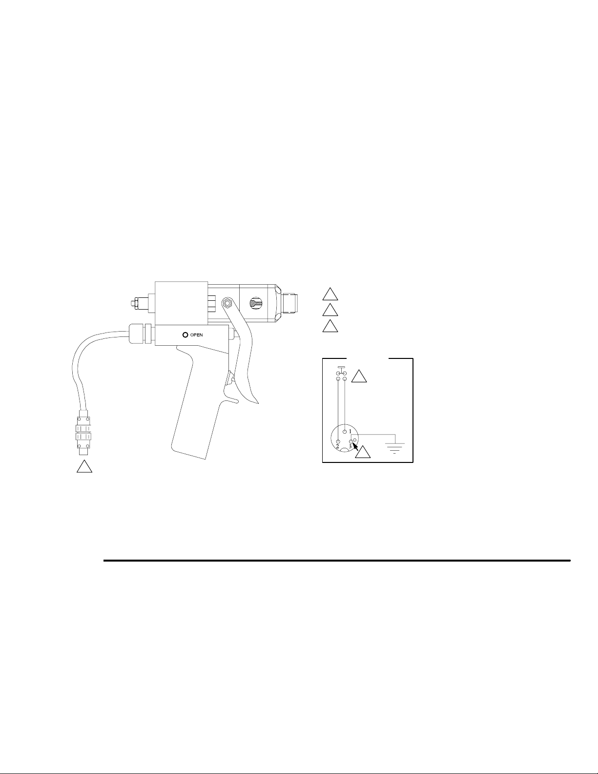
Electric Switch Hand Held Valve
Install a remote 4-way air control valve to operate the
valve. Connect an OPEN air signal air line to the 1/8
npt(f) port on the side of the valve. Connect a CLOSE
air signal air line to the 1/8 npt(f) port on the opposite
side of the valve. Wire the normally open valve switch
to the system control.
Machine Mount Valve
Install a remote 4-way air control valve to operate the
valve. Connect an open air signal air line to the 1/8
npt(f) OPEN port. Connect a close air signal air line to
the 1/8 npt(f) CLOSE port.
Air Switch Hand Held Valve
This valve has a single air inlet and an internal 4-way
spool valve, which directly operates the air piston.
Connect the air line to the 1/8 npt(f) air inlet.
1
Solder to terminals in cable connectors as shown in Detail A.
2
Normally open, momentary contact switch.
3
Ground connection.
1
Fig. 3
Detail A
2
3
Electric Switch Hand Held Valve shown
8370A
7308876
Page 8
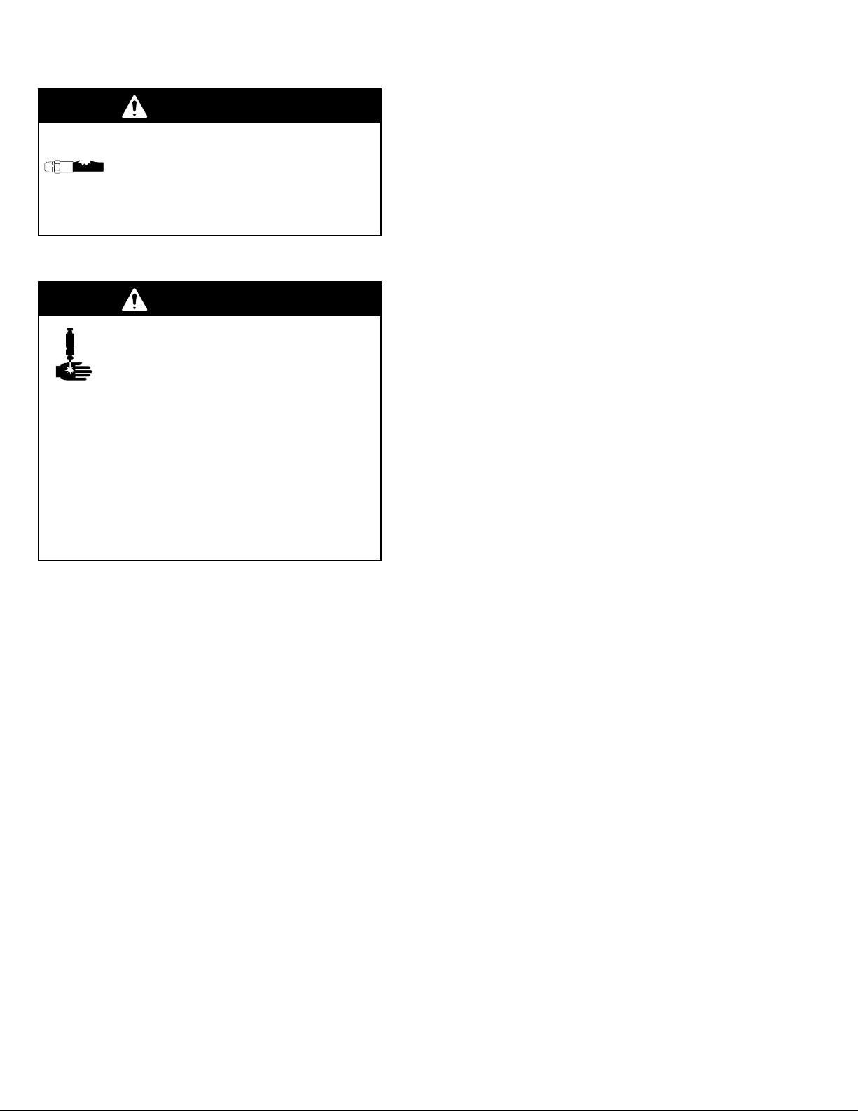
Operation
WARNING
COMPONENT RUPTURE HAZARD
To reduce the risk of over-pressurization,
which can cause component rupture and
serious injury, never exceed 3000 psi (21
MPa, 207 bar) fluid pressure, or 120 psi (0.84 MPa,
8.4 bar) air pressure to the valve.
Electric Switch Hand Held Valve
D Be sure the air supply lines are connected correctly
to the OPEN and CLOSE valve air ports.
D To open or close the valve and maintain the open or
closed status, a minimum of 40 psi (280 kPa, 2.8
bar) air pressure must be supplied and maintained
at the OPEN or CLOSE port.
Pressure Relief Procedure
WARNING
SKIN INJECTION HAZARD
The system pressure must be manually
relieved to prevent the system from
starting or spraying accidentally. Fluid
under high pressure can be injected through the
skin and cause serious injury. To reduce the risk of
an injury from injection, splashing fluid, or moving
parts, follow the Pressure Relief Procedure
whenever you:
D are instructed to relieve the pressure
D stop dispensing
D check or service any of the system equipment
D install or clean the nozzle
1. Shut off the air to the dispense valve, if applicable.
2. Shut off the air to the supply pumps.
3. Close the bleed-type master air valve (required in
your system).
4. Hold a metal part of the valve firmly to the side of a
grounded metal pail, and trigger the dispense
valve to relieve pressure.
5. Open the fluid drain valve (required in your
system), having a grounded metal container ready
to catch the drainage.
D The trigger only activates the electrical switch in the
handle, which turns the remote solenoid on and off.
D Trigger the gun to turn the solenoid on. Release the
trigger to turn the solenoid off.
Machine Mount Valve
D Be sure the air supply lines are connected correctly
to the OPEN and CLOSE valve air ports.
D To open or close the valve and maintain the open or
closed status, a minimum of 40 psi (280 kPa, 2.8
bar) air pressure must be supplied and maintained
at the OPEN or CLOSE port.
To open the valve:
1. Apply air pressure to the OPEN air port on the
valve, and remove air pressure from the CLOSE
air port on the valve.
2. Maintain air pressure on the OPEN air port to keep
the valve open.
To close the valve:
1. Apply air pressure to the CLOSE air port on the
valve, and remove air pressure from the OPEN air
port on the valve.
2. Maintain air pressure to the CLOSE air port to
keep the valve closed.
6. Leave the fluid drain valve open until you are ready
to dispense again.
If you suspect that the dispense needle or hose is
completely clogged, or that pressure has not been fully
relieved after following the steps above, very slowly
loosen the needle retaining nut or hose end coupling
and relieve pressure gradually, then loosen completely.
Now clear the needle or hose.
8 308876
Page 9
Operation
Air Switch Hand Held Valve
The valve operation is such that there are only two
valve conditions: either fully open or fully closed.
The valve is opened and closed by the internal air
control valve. Trigger the gun to open the valve.
Release the trigger to close the valve.
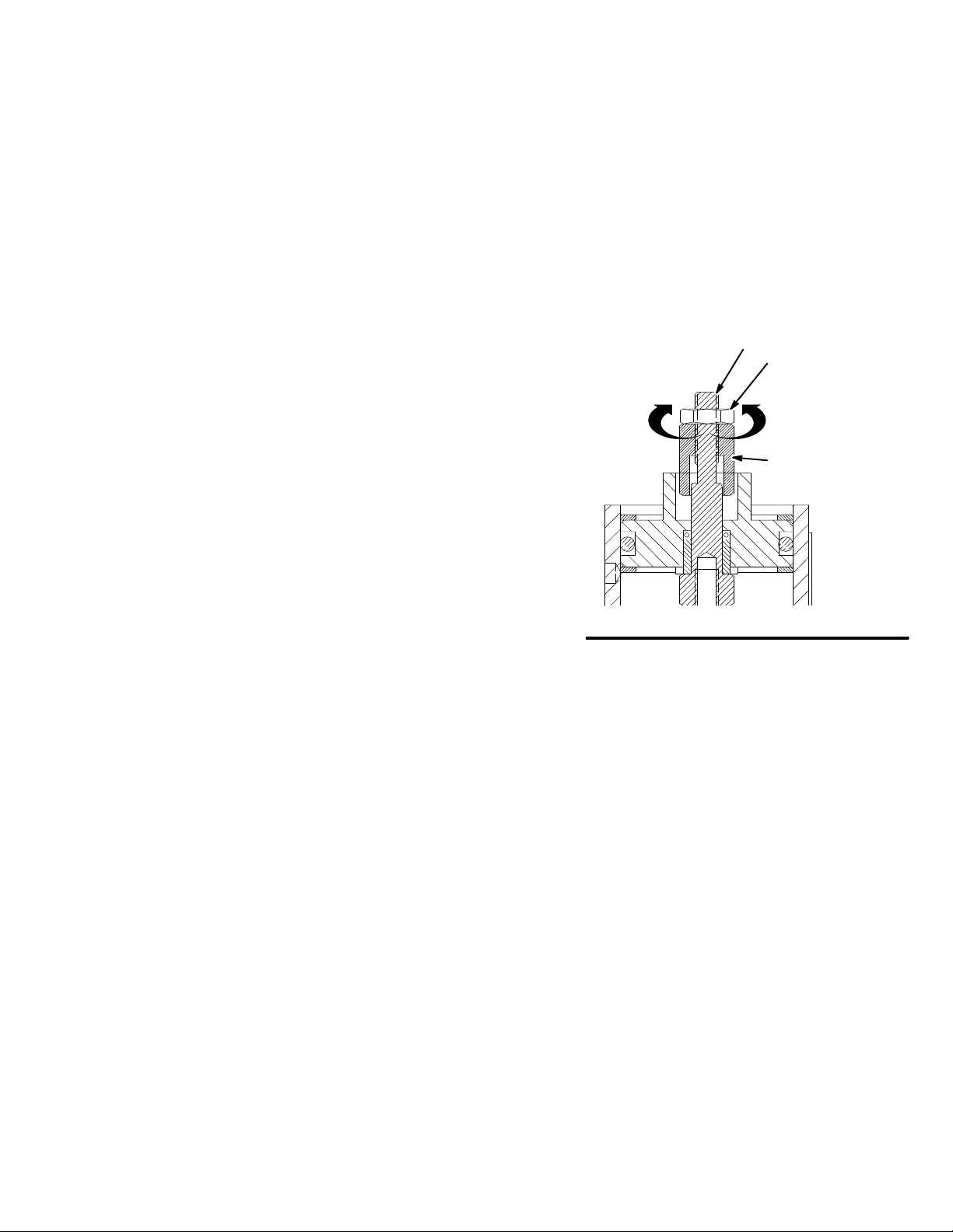
Shaft Stroke Adjustment (Models 965766,
965767, 965768, and 965786 only)
Adjust the shaft stroke to balance the valve between
“snuff-back” and “push-out”.
D A long stroke will give maximum snuff-back but it
may cause push-out when the valve opens.
D Shortening the stroke of the shaft will minimize the
material pushed out when the valve opens and will
also increase the material back pressure through
the valve.
To adjust the shaft stroke:
1. Loosen the hex nut (44) from the adjustment nut
(43).
D The valve is at full stroke when the hex nut
(44) is at the end of the adjustment shaft (42).
D Adjusting the nut (44) on the shaft (42)
towards the valve, or clockwise, will reduce the
stroke length.
D Adjusting the nut away from the valve, or
counterclockwise, will lengthen the stroke.
3. Tighten the hex nut (44) to the adjustment nut (43)
to set the adjustment.
42
44
Shorten Lengthen
43
2. Adjust the nut (44) along the adjustment shaft (42)
to the desired position.
Maintenance
Preventative Maintenance
There is a grease filled secondary seal/bearing area on
the valve shaft. Every 10,000 cycles, or twice each
month, new grease should be flushed across this area.
Each valve has two flush grease fittings. A small
grease gun is provided with each valve.
Fig. 4
To grease the valve:
1. Remove the grease fitting from one side of the
gun.
2. Pump grease (Part No. 115982) across the valve
until clear grease comes out of the other side.
3. Reinstall the grease fitting.
8460
9308876
Page 10

WARNING
SKIN INJECTION HAZARD
To reduce the risk of serious injury
whenever you are instructed to relieve
pressure, always follow the Pressure
Relief Procedure on page 8.
Troubleshooting
1. Relieve the pressure.
2. Check all possible causes to the problem before
disassembling the pump.
PROBLEM
Valve does not open Insufficient air pressure Turn on or turn up air pressure.
Valve does not close
(leaks)
Higher than normal
back-pressure
CAUSE SOLUTION
Air not exhausted from behind air cylinder piston
Shaft adjustment too far closed Adjust the shaft stroke as instructed on page 9.
Insufficient air pressure Turn on or turn up air pressure.
Air not exhausted from behind air cylinder piston
Blockage between needle and seat Remove and clean needle and seat.
Bad or missing gasket between seat
and housing
Needle worn out Replace needle and seat.
Nosepiece plugging up Remove and clean.
Use four-way, relieving-type air valve operator.
Use four-way, relieving-type air valve operator.
Replace gasket (38).
10 308876
Page 11

Service
(Models 965766, 965767, 965768, and 965786 only)
12. Remove the pin (7), o-ring (9), and piston o-ring
WARNING
(6).
SKIN INJECTION HAZARD
To reduce the risk of serious injury
whenever you are instructed to relieve
pressure, always follow the Pressure
Relief Procedure on page 8.
Disassembly
1. Relieve all air and fluid pressure.
2. Disconnect the valve from the system.
3. Remove the four nosepiece screws (15), and pull
the nosepiece (40) away from the valve. Remove
the snuff-back ring (41). See Fig. 5, page 14.
4. Use an 1/8 in. pin punch in the needle hole (A) to
unscrew the needle (27). If the shaft (3) spins,
insert a dowel pin in the shaft hole (B) to hold it
steady, then unscrew the needle (27).
5. Remove the seat (25), gasket (38), and o-ring
(39).
6. Remove the two fluid housing screws (23) and
remove the fluid housing (26). Remove the primary
fluid seal (22) from the fluid housing (26).
7. Pull the bearing/lube housing (19) from the air
cylinder (1). Remove the bearing (21), bearing
o-ring (16), and secondary fluid seal (20). Remove
the grease fittings (18).
13. Use a 1/4 in. pin punch to knock out the bearings
(5) and o-rings (4).
Air Switch Handle (if equipped)
1. Remove the trigger (56).
2. Loosen the set screw above the trigger safety. Pull
off the handle (55).
3. Remove the four retaining screws (60). Pull the
housing (50) and gasket (30) away from the air
cylinder (1).
Air Valve
1. Unscrew the stem guide (58).
2. Remove the trigger pin (59), o-ring (57), spool
(49), spacers (51, 52), o-rings (46, 48) and spring
(47).
3. Remove the bushing (53) from the housing (50)
with the screw (54).
4. Remove the screws (60) and lock-washers (61)
from the air cylinder (1).
Electric Switch Handle (if equipped)
1. Disconnect the power from the gun.
2. The switch, housing, and cable are not repairable.
Replace these parts as a complete assembly.
8. Remove the C-clip (12) from the back of the air
cylinder (1). Push the shaft (3) into the air cylinder
to dislodge the air cylinder cap (11). Remove the
cap o-ring.
9. Remove the internal C-clip (12). Push the shaft (3)
to dislodge the piston (10) assembly from the air
cylinder (1).
10. Remove the adjustment nut (44) from the shaft (3).
11. Remove the adjustment shaft (42) from the shaft
(3).
3. Remove the trigger (56).
4. Loosen the setscrew above the trigger safety. Pull
off the handle (55).
5. Remove the four manifold retaining screws (60).
Pull the housing (50) and gasket (30) away from
the air cylinder (1).
6. Remove the bushing (53) from the housing (50)
with the screw (54).
7. Remove the screws (60) and lock-washers (61)
from the air cylinder (1).
11308876
Page 12

Service
(Models 965766, 965767, 965768, and 965786 only)
Reassembly
Air Cylinder Section
1. Lubricate the shaft o-rings (4) and the bearings (5)
with grease supplied in the repair kit. Insert o-rings
into the air cylinder (1) and air cap (11) cavities.
See Fig. 5.
2. Press the bearings (5) flush into the air cylinder
housing and air cap, trapping the o-rings (4).
3. Lubricate and reassemble the piston assembly;
piston (10), o-ring (9), dowel pin (7), adjustment
shaft (42), o-ring (6), and shaft (3). Use Loctiter
Primer N7649 and Loctiter TL242, 243, or
equivalent (“blue” Loctite) when assembling the
adjustment shaft (42). Tighten the shaft to 15–20
in–lb (1.7–2.2 NSm). The shaft (3) should hang
with some play to be self-aligning in the bearing.
4. Lubricate the air cylinder (1) ID with the grease
supplied. Push the piston (10) assembly into the
air cylinder.
5. Orient the air inlet manifold (2) (if used) as shown.
Match the gasket openings to the air ports.
Fluid Section
1. Lubricate the bearing (21), o-ring (16) and cup seal
(20). Put the o-ring (16) on the bearing. Carefully
insert the seal (20) into the bearing recess, with
the lips of the o-ring facing into the bearing. Be
careful not to damage the seal lips.
2. Push the bearing (21) seal end first into the
housing (19). Be sure that the grease hole in the
side of the bearing lines up with the grease ports in
the housing (19).
3. Holding the bearing (21) in place, push the bearing
assembly over the shaft (3).
4. Lubricate the main fluid seal (22) and its cavity in
the housing (26). Carefully press the seal, lip-first,
into the housing.
5. Push the housing (26) and seal (22) over the shaft
(3) and up against the bearing housing.
6. Apply anti–seize lubricant (Loctite 56765 or
equivalent) to the fluid housing screws (23) and
loosely install the screws to retain the housings.
Do not tighten the screws yet.
7. Insert the gasket (38) and seat (25). These items
are reversible and can be installed in either
direction.
8. Use Loctite Primer N7649 and Loctite TL242, 243,
or equivalent (“blue” Loctite) when assembling the
needle (27) and tighten to 15–20 in–lb (1.7–2.2
NSm).
9. Apply air pressure to the CLOSE port, or to the
pneumatic trigger valve if installed. This will align
the shaft, seal, and bearing. Tighten the fluid
housing screws (23) oppositely and evenly to
40–45 in-lbs (4.5–5 NSm).
10. Install the nosepiece (40) with the PTFE o-ring
(39), screw (15), and snuff-back ring (41), if used.
The snuff-back ring has an internal bevel on one
end which faces into the nosepiece. Tighten the
nosepiece screws to 15–20 in-lbs (1.7–2.2 NSm).
12 308876
Page 13

Service
(Models 965766, 965767, 965768, and 965786 only)
Air Valve (if equipped)
1. Insert the spring (51) into the housing (50).
2. Lubricate and install an o-ring (46) into the
housing.
3. Install a spacer (52), internal bevel first, into the
housing.
4. Lubricate and install two o-rings (46) and the
spacer (51).
5. Lubricate and install a spacer (52) with the internal
bevel out, and o-ring (46).
6. Lubricate and install o-rings (48) on the spool (49).
Insert the spool with the nub facing out.
7. Lubricate the pin (59) and insert it into the guide
(58). Screw the guide with o-ring (57) into the
housing. Tighten it to 60–70 in-lbs (6.8–7.9 NSm).
8. Orient the gasket (30) to the holes on the air
cylinder (1). Screw the air valve assembly to the
cylinder with the screws (60) and lock-washers
(61). TIghten the screws evenly to 15–20 in-lbs
(1.7–2.2 NSm).
9. Screw the bushing (53) to the housing (50) with
the screw (54). Tighten the screw to 140–150
in-lbs (15.8–16.9 NSm).
10. Attach the handle (55) with the setscrew.
11. Attach the trigger (56) with the grease fittings (18).
12. Test that the trigger safety works properly.
Electric Switch
1. The switch, housing, and cable are not repairable.
Replace these parts as a complete assembly.
2. The switch, housing, and cable assembly are not
user serviceable and must be replaced as an
assembly.
13308876
Page 14
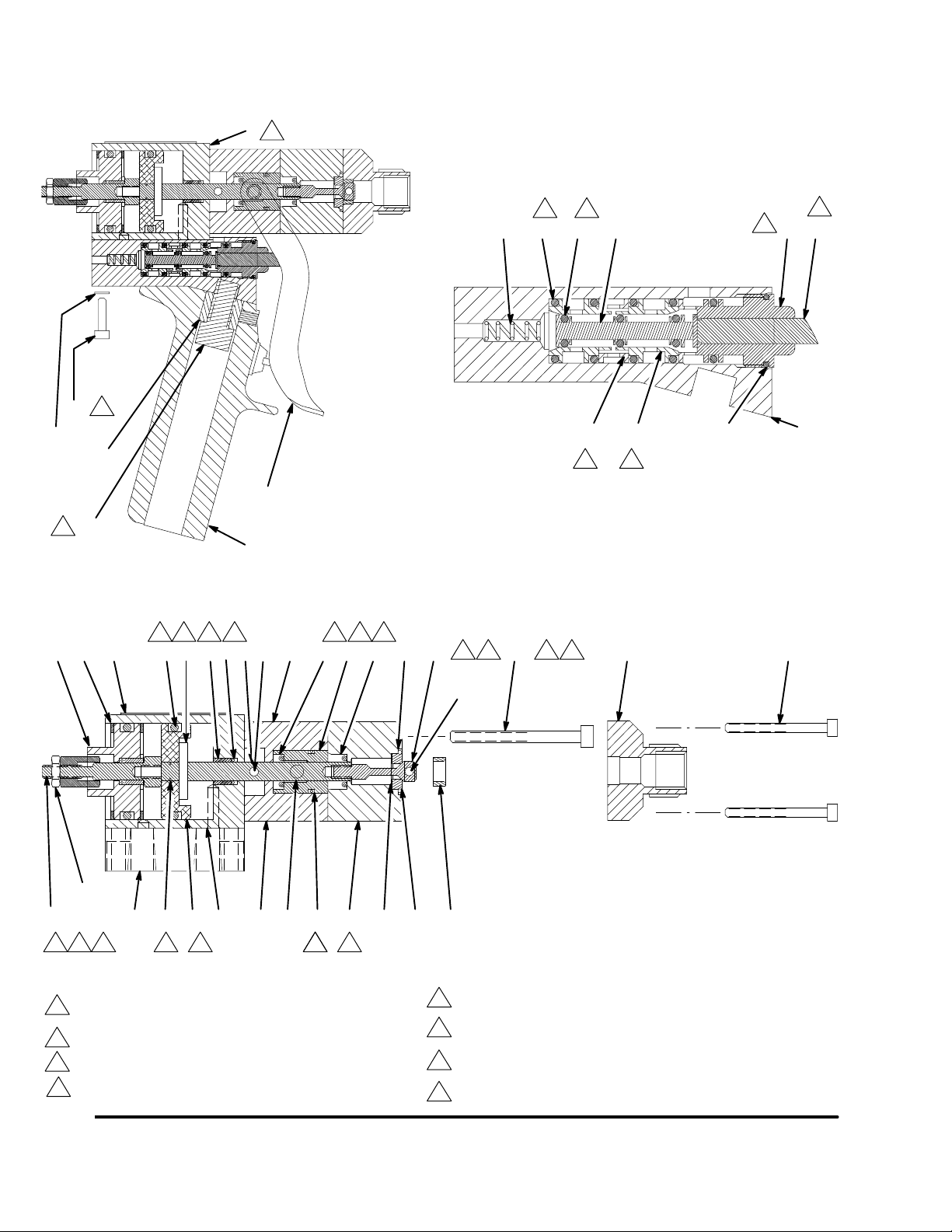
Service
(Models 965766, 965767, 965768, and 965786 only)
1
4
61
4
58 59
8370A
60
2
53
4
4
4647 48 49
51 52
5
57 50
44
56
6
54
1211
13, 14
8375B
44
4 4
6 5 34 28, 29 20 21 22 39
7
55
44
B
2 3
27
7 8
23 40
15
44
42
1
4 4 4
Tighten to 15–20 in-lb (1.7–2.2 NSm). The shaft should hang
1
with some play to be self-aligning in the bearing.
2
Tighten to 15–20 in-lbs (1.7–2.2 NSm).
3
Tighten oppositely and evenly to 40–45 in-lbs (4.5–5 NSm).
4
Lubricate with grease supplied in the repair kit.
2910 16
7
30
19 18
4444
Fig. 5
26
38 25
A
41
5
Tighten to 60–70 in-lbs (6.8–7.9 NSm).
Screw the bushing (53) to the housing (50) with screw (54).
6
Tighten to 140–150 in-lbs (15.8–16.9 NSm).
Apply Loctite Primer N7649 and Loctite TL242, 243, or
7
equivalent (“blue” Loctite).
Apply anti–seize lubricant (Loctite 56765 or equivalent).
8
8371A
14 308876
Page 15

Notes
15308876
Page 16

Parts
(Models 965766, 965767, 965768, and 965786 only)
15
19
18
30 12
1
(965766 &
965786 only)
26
2
9
10
16
38
25
41
42
44
43
11
6
7
5
4
3
28, 29
20
21
22
39
27
23
40
15
8371A
16 308876
Page 17

Parts
Model 965766
Machine Mount Valve
Stainless steel wetted parts
Model 965786
Automatic Machine Mount Valve
Aluminum wetted parts
Ref.
No.
1 626702 HOUSING, air cylinder 1
2 626069 MANIFOLD, air control 1
3 626068 SHAFT, air cylinder 1
4* 156454 O-RING, 010 buna-n 2
5* 551181 BEARING, air cylinder 2
6* 154662 O-RING, 222 buna-n 2
7* 552164 DOWEL PIN 1
9* 157628 O-RING, 006 buna-n 1
10 626703 PISTON, air cylinder 1
11 626704 CAP, air cylinder CAP, air
12 552163 CLIP, internal 1.75 2
13 102817 SCREW, drive 2
14 552161 PLATE, identification 1
15 104371 SCREW, 10–32 x 0.375 4
16*† 103610 O-RING, 014
18 551188 FLUSH GREASE FITTING 2
19 626705 LUBE HOUSING 1
20*† 551191 U-CUP, urethane/EPR 1
21* 626064 BEARING, lube 1
22*† 551190 U-CUP, Polymitet/EPR 1
23n 103926 SCREW, 1/4–20 x 2.25 2
25* 185467 SEAT, C2 carbide 1
26 626731 HOUSING, fluid; stainless
27*} 626062 NEEDLE, hardened stain-
28Y 188377 LABEL, skin injection haz-
29Y 188378 LABEL, read instruction
Part No. Description Qty.
cylinder; Models 965766
and 965786 only
196018 CAP, air cylinder; Models
243482 and 243666 only
fluoroelastomer
steel; Model 965766 and
243282 only
626706 HOUSING, fluid; aluminum;
Model 965786 only
less steel
ard
manual
Model 243482
Orbiter Mounted Valve
Stainless steel wetted parts
Model 243666
PrecisionFlo Control Valve
Stainless steel wetted parts
Ref.
No.
30* 626057 GASKET, air cylinder 1
31 104459 SCREW, 10–32 x 1.75 4
35* 551186 GREASE, 3 oz. tube (not
36 115982 GUN, grease (not shown) 1
37 551187 COUPLER, flush grease
38*† 171860 GASKET, seat 1
39*† 104319 O-RING, 014 PTFE 1
1
1
1
1
1
1
1
1
40 626732 NOSEPIECE, stainless
41* 626060 RING, snuff-back 1
42} 626708 SHAFT, adjustment Models
43 626709 NUT, adjustment Models
44 100166 NUT, full hex, 10–32 Mod-
45 102920 NUT, jam, 10–32 Models
* Included in Rebuild Kit 570268.
† Included in Section Seal Kit 570267.
Y Replacement Instruction and Warning Labels are
} Use Loctite Primer N7649 and Loctite TL242, 243,
n Use anti–seize lubricant (Loctite 56765 or
Part No. Description Qty.
shown)
(not shown)
steel; Models 965766 and
243666 only
626707 NOSEPIECE; aluminum;
Model 965786 only
195957 NOSEPIECE; stainless
steel; Model 243482 only
965766 and 965786 only
965766 and 965786 only
els 965766 and 965786 only
243482 and 2436666 only
available at not cost.
or equivalent (“blue” Loctite) when assembling this
part.
equivalent) when assembling 965766 and 965786.
Use Loctite TL242, 243, or equivalent (“blue”
Loctite) when assembling 243482 and 243666.
1
1
1
1
1
1
1
1
1
17308876
Page 18

61
Parts
63
(965768 only)
60
53
56
54
8375B
55
(965767 only)
47
46 48 49
8370A
58 59
18 308876
51 52
57 50
8372A
Page 19

WARNING
SKIN INJECTION HAZARD
To reduce the risk of serious injury
whenever you are instructed to relieve
pressure, always follow the Pressure
Relief Procedure on page 8.
Service
(Models 243482 and 243666 only)
6. Remove the two fluid housing screws (23) and
remove the fluid housing (26). Remove the primary
fluid seal (22) from the fluid housing (26).
7. Pull the bearing/lube housing (19) from the air
cylinder (1). Remove the bearing (21), bearing
o-ring (16), and secondary fluid seal (20). Remove
the grease fittings (18).
Disassembly
1. Relieve all air and fluid pressure.
2. Disconnect the valve from the system.
3. Remove the four nosepiece screws (15), and pull
the nosepiece (40) away from the valve. Remove
the snuff-back ring (41). See Fig. 5, page 14.
4. Use an 1/8 in. pin punch in the needle hole (A) to
unscrew the needle (27). If the shaft (3) spins,
insert a dowel pin in the shaft hole (B) to hold it
steady, then unscrew the needle (27).
5. Remove the seat (25), gasket (38), and o-ring
(39).
8. Remove the C-clip (12) from the back of the air
cylinder (1). Push the shaft (3) into the air cylinder
to dislodge the air cylinder cap (11). Remove the
cap o-ring.
9. Remove the internal C-clip (12). Push the shaft (3)
to dislodge the piston (10) assembly from the air
cylinder (1).
10. Remove the pin (7), o-ring (9), and piston o-ring
(6).
11. Use a 1/4 in. pin punch to knock out the bearings
(5) and o-rings (4).
19308876
Page 20

Service
(Models 243482 and 243666 only)
Reassembly
Air Cylinder Section
1. Lubricate the shaft o-rings (4) and the bearings (5)
with grease supplied in the repair kit. Insert o-rings
into the air cylinder (1) and air cap (11) cavities.
See Fig. 5.
2. Press the bearings (5) flush into the air cylinder
housing and air cap, trapping the o-rings (4).
3. Lubricate and reassemble the piston assembly;
piston (10), o-ring (9), dowel pin (7), o-ring (6), and
shaft (3). Tighten the jam nut (45) to 15–20 in-lb
(1.7–2.2 NSm). The shaft (3) should hang with
some play to be self-aligning in the bearing.
4. Lubricate the air cylinder (1) ID with the grease
supplied. Push the piston (10) assembly into the
air cylinder.
5. Orient the air inlet manifold (2) (if used) as shown.
Match the gasket openings to the air ports.
Fluid Section
1. Lubricate the bearing (21), o-ring (16) and cup seal
(20). Put the o-ring (16) on the bearing. Carefully
insert the seal (20) into the bearing recess, with
the lips of the o-ring facing into the bearing. Be
careful not to damage the seal lips.
2. Push the bearing (21) seal end first into the
housing (19). Be sure that the grease hole in the
side of the bearing lines up with the grease ports in
the housing (19).
3. Holding the bearing (21) in place, push the bearing
assembly over the shaft (3).
4. Lubricate the main fluid seal (22) and its cavity in
the housing (26). Carefully press the seal, lip-first,
into the housing.
5. Push the housing (26) and seal (22) over the shaft
(3) and up against the bearing housing.
6. Apply Loctite Primer N7649 and Loctite TL242,
243, or equivalent (“blue” Loctite) to the fluid
housing screws (23) and loosely install the screws
to retain the housings. Do not tighten the screws
yet.
7. Insert the gasket (38) and seat (25). These items
are reversible and can be installed in either
direction.
8. Apply Loctite Primer N7649 and Loctite TL242,
243, or equivalent (“blue” Loctite) to needle (27)
and tighten to 15–20 in–lb (1.7–2.2 NSm).
9. Apply air pressure to the CLOSE port, or to the
pneumatic trigger valve if installed. This will align
the shaft, seal, and bearing. Tighten the fluid
housing screws (23) oppositely and evenly to
40–45 in-lbs (4.5–5 NSm).
10. Install the nosepiece (40) with the PTFE o-ring
(39), screw (15), and snuff-back ring (41), if used.
The snuff-back ring has an internal bevel on one
end which faces into the nosepiece. Tighten the
nosepiece screws to 15–20 in-lbs (1.7–2.2 NSm).
20 308876
Page 21

Parts
(Models 243482 and 243666 only)
12
22 22
2 2
6 5 34 28, 29 20 21 22 39 23 40
13, 14
45
2910 16
Tighten oppositely and evenly to 40–45 in-lbs (4.5–5 NSm).
1
2
Lubricate with grease supplied in the repair kit.
3
Tighten to 15–20 in lbs (17–22 NSm)
4
Apply Loctite Primer N7649 and Loctite TL242, 243, or equivalent
(“blue” Loctite).
7
2 2
30
19 18
222
26
38 25
4
3
27
4
1
40
Model 243482
15
15
Fig. 6
21308876
Page 22

Parts
(Models 243482 and 243666 only)
15
19
18
30
1
9
10
16
38
26
25
41
12
19
45
6
7
5
4
3
28, 29
20
21
22
39
27
Model 243482
31
40
23
40
31
8371A
22 308876
Page 23

Parts
Model 965767
Hand Held Valve with Pneumatic Trigger
Aluminum wetted parts
See page 16 for illustration of items 1–44. See page 18 for illustration of items 46–62.
Ref.
No.
1 626702 HOUSING, air cylinder 1
3 626068 SHAFT, air cylinder 1
4* 156454 O-RING, 010 buna-n 2
5* 551181 BEARING, air cylinder 2
6* 154662 O-RING, 222 buna-n 2
7* 552164 DOWEL PIN 1
9* 157628 O-RING, 006 buna-n 1
10 626703 PISTON, air cylinder 1
11 626704 CAP, air cylinder 1
12 552163 CLIP, internal 1.75 2
13 102817 SCREW, drive, #0 x 0.25 2
14 552161 PLATE, identification 1
16*† 103610 O-RING, 014
18 551188 FLUSH GREASE FITTING 2
19 626705 LUBE HOUSING 1
20*† 551191 U-CUP, urethane/EPR 1
21* 626064 BEARING, lube 1
22*† 551190 U-CUP, Polymitet/EPR 1
23n 103926 SCREW, 1/4–20 x 2.25 2
25* 185467 SEAT, C2 carbide 1
26 626706 HOUSING, fluid; aluminum 1
27*} 626062 NEEDLE, hardened stain-
28Y 188377 LABEL, skin injection haz-
29Y 188378 LABEL, read instruction
30* 626057 GASKET, air cylinder 1
31 104459 SCREW, 10–32 x 1.75 4
35* 115982 GREASE, 3 oz. tube (not
36 551189 GUN, grease (not shown) 1
37 551187 COUPLER, flush grease
38*† 171860 GASKET, seat 1
39*† 104319 O-RING, 014 PTFE 1
Part No. Description Qty.
fluoroelastomer
less steel
ard
manual
shown)
(not shown)
Ref.
No.
40 626707 NOSEPIECE, aluminum 1
41* 626060 RING, snuff-back 1
42} 626708 SHAFT, adjustment 1
43 626709 NUT, adjustment 1
44 100166 NUT, full hex, 10–32 1
46 106559 O-RING, No. 905
47 106561 SPRING 1
48 106560 O-RING, 007
49 178651 SPOOL, 4-way 1
50 626056 HOUSING, air valve 1
1
1
1
1
1
1
51 178652 SPACER, u-shape 1
52 178653 SPACER, air valve 2
53 626055 BUSHING, handle 1
54 551204 SCREW, 3/8–16 x 3/4 1
55 626075 HANDLE 1
56 626083 TRIGGER 1
57 106551 O-RING, 0.5 x 0.6
58 178654 GUIDE, stem 1
59 626053 PIN, trigger 1
60 119156 SCREW, 10–32 x 0.8125 4
61 100020 WASHER, lock, #10 2
62 104765 PLUG, pipe, headless,
* Included in Rebuild Kit 570268.
† Included in Section Seal Kit 570267.
Y Replacement Instruction and Warning Labels are
} Loctite Primer N7649 and Loctite TL242, 243, or
n Anti–seize lubricant (Loctite 56765 or equivalent)
Part No. Description Qty.
5
fluoroelastomer
3
fluoroelastomer
1
fluoroelastomer
1
1/8 npt (not shown)
available at no cost.
equivalent (“blue” Loctite) should be used when
installing this part.
should be used when installing this part.
23308876
Page 24

Parts
Model 965768
Hand Held Valve with Electric Switch
Aluminum wetted parts
See page 16 for illustration of items 1–44. See page 18 for illustration of items 53–63.
Ref.
No.
1 626702 HOUSING, air cylinder 1
3 626068 SHAFT, air cylinder 1
4* 156454 O-RING, 010 buna-n 2
5* 551181 BEARING, air cylinder 2
6* 154662 O-RING, 222 buna-n 2
7* 552164 DOWEL PIN 1
9* 157628 O-RING, 006 buna-n 1
10 626703 PISTON, air cylinder 1
11 626704 CAP, air cylinder 1
12 552163 CLIP, internal 1.75 2
14 552161 PLATE, identification 1
15 104371 SCREW, 10–32 x 0.375 4
16*† 103610 O-RING, 014
18 551188 FLUSH GREASE FITTING 2
19 626705 LUBE HOUSING 1
20*† 551191 U-CUP, urethane/EPR 1
21* 626064 BEARING, lube 1
22*† 551190 U-CUP, Polymitet/EPR 1
23n 103926 SCREW, 1/4–20 x 2.25 2
25* 185467 SEAT, C2 carbide 1
26 626706 HOUSING, fluid; aluminum 1
27*} 626062 NEEDLE, hardened stain-
28Y 188377 LABEL, skin injection haz-
29Y 188378 LABEL, read instruction
30* 626057 GASKET, air cylinder 1
31 104459 SCREW, 10–32 x 1.75 4
35* 115982 GREASE, 3 oz. tube (not
Part No. Description Qty.
fluoroelastomer
less steel
ard
manual
shown)
Ref.
No.
36 551189 GUN, grease (not shown) 1
37 551187 COUPLER, flush grease
38*† 171860 GASKET, seat 1
39*† 104319 O-RING, 014 PTFE 1
40 626707 NOSEPIECE, aluminum 1
41* 626060 RING, snuff-back 1
42} 626708 SHAFT, adjustment 1
43 626709 NUT, adjustment 1
44 100166 NUT, full hex, 10–32 1
53 626055 BUSHING, handle 1
54 551204 SCREW, 3/8–16 x 3/4 1
1
1
1
1
1
55 626075 HANDLE 1
56 626083 TRIGGER 1
60 119156 SCREW, 10–32 x 0.8125 4
61 100020 WASHER, lock, #10 2
63 949706 SWITCH ASSEMBLY 1
* Included in Rebuild Kit 570268.
† Included in Section Seal Kit 570267.
Y Replacement Instruction and Warning Labels are
} Loctite Primer N7649 and Loctite TL242, 243, or
n Anti–seize lubricant (Loctite 56765 or equivalent)
Part No. Description Qty.
1
(not shown)
available at not cost.
equivalent (“blue” Loctite) should be used when
installing this part.
should be used when installing this part.
24 308876
Page 25

Accessories
Plastic Tube Fittings to Connect Air Signals
Tube OD 1/8 NPT (M) Straight 1/8 NPT (M) 90º Swivel Tube Tee
1/8 in.
5/32 in.
1/4 in.
Tube OD 1/4 NPT (M) Straight 1/4 NPT (M) 90º Swivel
5/32 in.
1/4 in.
598329
104172
598252
104165
513826
598140
597151
598327
C19391
551203
514435
111167
Plastic Tubing for Air Signal Lines
Part No. Description
513063 1/8 in. O.D. Nylon
514607 5/32 in. O.D. Nylon
C12509 1/4 in. O.D. Nylon
Air Signal Accessories
551201 Air Cylinder Speed Control 90_ Fitting
1/8 npt(f) inlet, 1/8 npt(m) outlet
Mount on CLOSE port to control opening speed for
soft start. Mount on OPEN port to control closing
speed for less snuff–back.
104661 Quick Exhaust Valve
1/8 npt(f) inlet and outlet, 1/4 npt(f) exhaust
Used to speed up opening or closing action of the 1K
Ultra–Lite Valve
104632 Pump Pilot Valve
1/2 npt (f) line ports, 1/8 npt(f) pilot port
3–way air piloted air valve to turn air powered
proportioning pump on with hand gun signal.
4-Way Solenoids and Solenoid
Accessories
626144 Manifold
To direct mount solenoid to 1K Ultra–Lite Valve.
551316 120 Volt ac Solenoid
For use with 626144 Manifold.
551317 24 Volt dc Solenoid
For use with 626144 Manifold.
551347 120 Volt ac Solenoid
Remote mount, 1/8 npt (f) ports
551348 24 Volt dc Solenoid
Remote mount, 1/8 npt(f) ports
551349 120 Volt ac Din Plug
With screw terminals for above solenoids
551350 24 Volt dc Din Plug
With screw terminals for above solenoids
Optional Main Fluid Needle Packings (22)
Part No. Description
551192 Urethane U–Cup with EPDM o–ring
spreader
551193 Reinforced PTFE U–Cup with 302
stainless steel spreader
25308876
Page 26

Accessories
Fluid Nozzles
Zinc-plated steel nozzles, 1/8 npt*
Part No. Orifice Length
607665 0.125 in. (3.17 mm) 2 in. (51 mm)
161505 0.09 in. (2.28 mm) 2 in. (51 mm)
164799 0.055 in. (1.39 mm) 2-1/8 in. (54 mm)
* Requires a 1/8 npt(f) bushing. Order 168683 Nozzle
Bushing.
Nozzles for use with 188253
flange nut.
8462A
Part No. Orifice Length
C00005 0.187 in. (4.75 mm) 1.656 in. (42 mm)
C00007 0.093 in. (2.36 mm) 2 in. (51 mm)
C00008 0.250 in. (2.28 mm) 2 in. (51 mm)
C00009 0.172 in. (4.37 mm) 2 in. (51 mm)
C00010 0.062 in.(1.57 mm) 2 in. (51 mm)
C00011 0.375 in. (9.53 mm) 2 in. (51 mm)
C00012 0.156 in. (3.96 mm) 2 in. (51 mm)
C00013 0.046 in. (1.17 mm) 2 in. (51 mm)
C00014 0.031 in. (0.79 mm) 2 in. (51 mm)
C00015 0.156 in. (3.96 mm) 1.812 in. (46 mm)
168683 Nozzle Bushing
Zinc-plated steel, 1/8 npt
Kits
949631 Conversion Kit
Pneumatic 4–way valve with housing, handle, and
trigger and other parts necessary to convert 965766 or
965786 to a hand held valve.
949632 Conversion Kit
Electric switch style handle kit to convert 965766 or
965786 to a hand held valve.
570267 Seal Kit
With Polymitet main packing (standard)
570268 Rebuild Kit
With Polymitet main packing (standard)
570299 Seal Kit
With PTFE main packing (optional)
570300 Rebuild Kit
With PTFE main packing (optional)
512135 Plastic Fluid Nozzle
1/4 npt, 0.062 in. (1.57 mm) orifice, 2-1/2 in.
(63.5 mm) long
26 308876
Page 27

Technical Data
Category Data
Maximum Fluid Pressure 4000 psi (28 MPa, 276 bar)
Maximum Cylinder Air Pressure 120 psi (0.84 MPa, 8.4 bar)
Air inlets (open and close ports) 1/8 npt(f)
Fluid Inlet 1/4 npt(f)
Fluid Outlet 1/4 npt(f) and 3/4–16 unf(m)
Fluid Viscosity Range 20 cps to 1 million cps
Snuffer Action Fluid Section Isolation chamber with zerk fittings
Divorced Air Cylinder Piston cylinder, EP o-rings
Weight
Aluminum Valve
Stainless Steel Valve
Handle Kit
Wetted Parts
Aluminum Valve aluminum, 303 stainless steel, 17–4 PH stainless steel, C2 car-
Stainless Steel Valve 303 stainless steel, 17–4 PH stainless steel, C2 carbide, hard
Severe-duty Components
Shaft
Snuffer Needle
Seat
Shaft Seal, standard
Shaft Seal, optional
1.43 lb (0.65 kg)
2.07 lb (0.94 kg)
0.77 lb (0.35 kg)
bide, hard chrome, ethylene propylene, Parker Polymitet, PTFE
chrome, ethylene propylene, Parker Polymitet, PTFE
Hard chrome over 303 stainless steel
Hardened 440–C stainless steel
Reversible, solid C2 carbide inserts
High density Parker Polymitet
PTFE
Loctiter is a registered trademark of the Loctite Corporation.
27308876
Page 28

Dimensions
6.13 in.
(155.7 mm)
1.42 in.
(36.07 mm)
1.75 in.
(44.45 mm)
2.25 in.
(57.15 mm)
0.88 in.
(22.35 mm)
1.75 in.
(44.45 mm)
3.5 in.
(88.9 mm)
1.63 in.
(41.4 mm)
2.25 in.
(57.15 mm)
Direct Mount Solenoid
(optional)
5 in.
(127 mm)
8370A
28 308876
Page 29

Notes
29308876
Page 30

Graco Standard Warranty
Graco warrants all equipment manufactured by Graco and bearing its name to be free from defects in material and workmanship on the
date of sale to the original purchaser for use. With the exception of any special, extended, or limited warranty published by Graco,
Graco will, for a period of twelve months from the date of sale, repair or replace any part of the equipment determined by Graco to be
defective. This warranty applies only when the equipment is installed, operated and maintained in accordance with Graco’s written
recommendations.
This warranty does not cover, and Graco shall not be liable for general wear and tear, or any malfunction, damage or wear caused by
faulty installation, misapplication, abrasion, corrosion, inadequate or improper maintenance, negligence, accident, tampering, or
substitution of non–Graco component parts. Nor shall Graco be liable for malfunction, damage or wear caused by the incompatibility of
Graco equipment with structures, accessories, equipment or materials not supplied by Graco, or the improper design, manufacture,
installation, operation or maintenance of structures, accessories, equipment or materials not supplied by Graco.
This warranty is conditioned upon the prepaid return of the equipment claimed to be defective to an authorized Graco distributor for
verification of the claimed defect. If the claimed defect is verified, Graco will repair or replace free of charge any defective parts. The
equipment will be returned to the original purchaser transportation prepaid. If inspection of the equipment does not disclose any defect
in material or workmanship, repairs will be made at a reasonable charge, which charges may include the costs of parts, labor, and
transportation.
THIS WARRANTY IS EXCLUSIVE, AND IS IN LIEU OF ANY OTHER WARRANTIES, EXPRESS OR IMPLIED, INCLUDING BUT
NOT LIMITED TO WARRANTY OF MERCHANTABILITY OR WARRANTY OF FITNESS FOR A PARTICULAR PURPOSE.
Graco’s sole obligation and buyer’s sole remedy for any breach of warranty shall be as set forth above. The buyer agrees that no other
remedy (including, but not limited to, incidental or consequential damages for lost profits, lost sales, injury to person or property, or any
other incidental or consequential loss) shall be available. Any action for breach of warranty must be brought within two (2) years of the
date of sale.
Graco makes no warranty, and disclaims all implied warranties of merchantability and fitness for a particular purpose in connection
with accessories, equipment, materials or components sold but not manufactured by Graco. These items sold, but not manufactured
by Graco (such as electric motors, switches, hose, etc.), are subject to the warranty, if any, of their manufacturer. Graco will provide
purchaser with reasonable assistance in making any claim for breach of these warranties.
In no event will Graco be liable for indirect, incidental, special or consequential damages resulting from Graco supplying equipment
hereunder, or the furnishing, performance, or use of any products or other goods sold hereto, whether due to a breach of contract,
breach of warranty, the negligence of Graco, or otherwise.
FOR GRACO CANADA CUSTOMERS
The parties acknowledge that they have required that the present document, as well as all documents, notices and legal proceedings
entered into, given or instituted pursuant hereto or relating directly or indirectly hereto, be drawn up in English. Les parties
reconnaissent avoir convenu que la rédaction du présente document sera en Anglais, ainsi que tous documents, avis et procédures
judiciaires exécutés, donnés ou intentés à la suite de ou en rapport, directement ou indirectement, avec les procedures concernées.
Graco Information
TO PLACE AN ORDER, contact your Graco distributor, or call one of the following numbers
to identify the distributor closest to you:
1–800–328–0211 Toll Free
612–623–6921
612–378–3505 Fax
For the latest information about Graco products, visit www.graco.com.
All written and visual data contained in this document reflects the latest product information available at the time of publication.
Graco reserves the right to make changes at any time without notice.
30 308876
This manual contains English. MM 308876
Graco Headquarters: Minneapolis
International Offices: Belgium, China, Japan, Korea
GRACO INC. P.O. BOX 1441 MINNEAPOLIS, MN 55440–1441
Copyright 1998, Graco Inc. is registered to ISO 9001
www.graco.com
Revised 04/2009
 Loading...