

Page 1
INSTRUCTIONS
g
ying
g
g
y
y
This manual contains important
warnings and information.
READ AND RETAIN FOR REFERENCE
Instructions
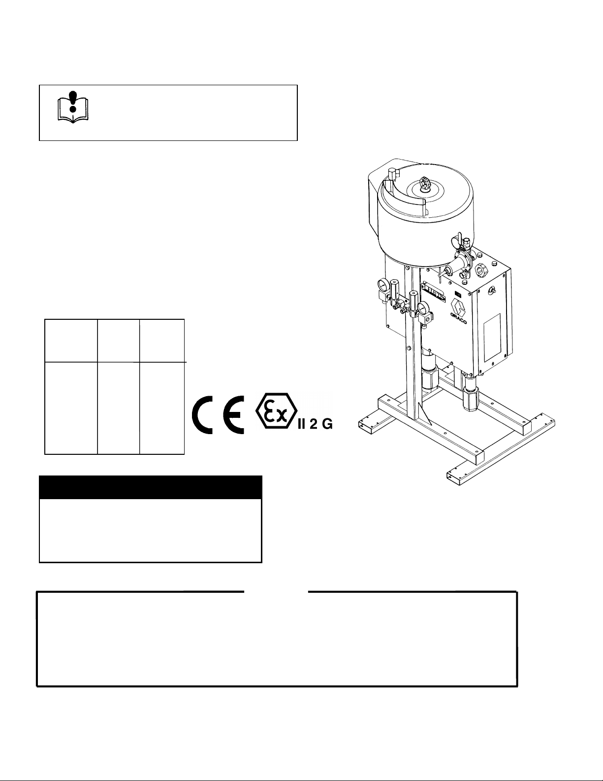
Air-Powered King and Premier
Hydra-Cat® H.P.
Variable Ratio
Proportioning Pump
100 PSI (7 bar) Maximum Working Air Pressure
5000 PSI (333 bar) Maximum Working Fluid Pressure
Model: See Chart
684025
Revision E
Assembly Ratio Ratio
Part # Min. Max.
965478 1.50 4.50
965466 3.00 9.00
965477 1.00 3.00
965479 2.00 6.00
965481 1.50 4.50
WARNING
MOVING PARTS HAZARD
Relieve fluid and air pressure to unit before
servicin
removed. Follow pressure relief procedure on
page 11.
Graco Inc. does not manufacture or supply any of the reactive chemical components that are used in this equipment
and is not responsible for their effects. Because of the vast number of chemicals that could be used and their
var
used, includin
potential dan
individual components or their resultant mixtures. Graco assumes no responsibilit
claims for bodil
components.
unit. Do not operate with panels
WARNING
chemical reactions, the buyer and user of this equipment should determine all factors relating to the fluids
any of the potential hazards involved. Particular inquiry and investigation should be made into
ers relating to toxic fumes, fires, explosions, reaction times, and exposure of human beings to the
for loss, damage, expense or
injury or property damage, direct or consequential, arising from the use of such chemical
GRACO INC. P.O. BOX 1441 MINNEAPOLIS, MN 55440-1441
Copyright 1998 Graco Inc.
Page 2

Table of Contents
Symbols.............................................................................3
Definition of Terms ............................................................3
Warnings ...........................................................................3
Specification of Hydra-Cat H.P. Pumps ............................6
Installation .........................................................................6
Connect the Fluid Supply Line....................................6
Connect the Fluid Output Lines ..................................6
System Accessories ...................................................7
Connect the Air Supply Line .......................................7
Pressure Relief Valve .................................................7
Electrical Grounding ...................................................8
Ratio Adjustment...............................................................9
Terms .........................................................................9
Determine the Ratio..................................................10
Relationship Between the Primary and
Secondary Pumps .................................................10
Adjusting the Ratio Setting .......................................10
Operation...................................................................... 11
Pressure Relief Procedure..................................... 11
System Flushing ....................................................11
Start the Pump....................................................... 11
Standard Operating Flushing ................................. 11
Checking the Ratio ................................................ 12
Maintenance................................................................. 12
Wet Cups ............................................................... 12
Bearings................................................................. 12
Air Lubrication ........................................................ 13
Troubleshooting............................................................ 14
Troubleshooting Techniques ................................. 14
Troubleshooting Chart ...........................................15
Service ......................................................................... 16
Required Tools ...................................................... 16
Disconnecting the Displacement Pump................. 16
Reconnecting the Displacement Pump ................. 17
Disconnecting the Air Motor................................... 17
Reconnecting the Air Motor ...................................17
Replacing the Bearings.......................................... 18
Dimensions................................................................... 19
Air Consumption........................................................... 19
Technical Data ............................................................. 21
Graco Information ........................................................ 22
Graco Standard Warranty ............................................ 22
2 684025
Page 3
Symbols
g
g
g
g
g
g
g
Warning Symbol Caution Symbol
WARNING CAUTION
This symbol alerts you to the possibility of serious injury
or death if you do not follow the instructions
Definition of Terms
WARNING: Alerts the user to avoid or correct conditions
which could cause serious injury.
CAUTION: Alerts the user to avoid or correct conditions
which could damage or destroy equipment.
NOTE: Identifies helpful information.
VRHC: The abbreviation for Variable Ratio Hydra–Cat
Pump. This pump automatically proportions and mixes two
fluids in a prescribed ratio, which is variable within the
ranges listed on the cover.
WARNING
This symbol alerts you to the possibility of damage to or
destruction of equipment if you do not follow the
instructions.
BASE: Also called polyol or resin, is one of two reactive
chemicals used in a plural component system.
CATALYST: Also called hardener, is the fluid which reacts
with the base fluid.
PART: An undefined unit of measurement. When you
determine the size of the unit (ounce, pint, gallon), use that
measurement consistently in setting up your system.
SPRAY GUN: This term refers to any type of spray gun or
dispensin
pumped.
valve used to spray or dispense the fluid bein
PLURAL COMPONENT FLUID HAZARD
Before usin
fluids used, includin
and exposure of human beings to the individual components of their resultant mixtures.
• Store hazardous fluid in an approved container. Dispose of hazardous fluid according to all local, state
and national guidelines.
• Wear the appropriate protective clothing, gloves, eyewear, and respirator.
• Graco does not manufacture or supply any of the reactive chemical components that may be used in
this equipment and is not responsible for their effects. Graco assumes no responsibility for loss,
dama
from the use of such chemical components.
MOVING PARTS HAZARD
Movin
pinch or amputate fingers.
• Do not operate the equipment with the guards removed.
• Keep your body and tools clear of any moving parts when starting or operating the equipment.
this equipment, read the fluid manufacturer’s warnings and determine all facts relating to the
any of the potential hazards relating to toxic fumes, fires, explosions, reaction times,
e, expense or claims for personal injury or property damage, direct or consequential, arisin
parts, such as the air motor piston and the secondary pump lever and connecting rod area, can
684025 3
Page 4
g
INSTRUCTION
g
g
g
g
g
g g
WARNING
FIRE AND EXPLOSION HAZARD
Improper
• Ground the equipment and the object being sprayed. See Electrical Grounding on page 8.
• Extinguish all the open flames or pilot lights in the spray area.
• Electrically disconnect all equipment in the spray area.
• Keep the spray area free of debris, including solvent, rags, and gasoline.
• Do not turn on or off any light switch in the spray area while operating or if fumes are present.
• Do not smoke in the spray area.
• Do not operate a gasoline engine in the spray area.
• If there is any static sparking while using this equipment, stop spraying immediately. Identify and
correct the problem.
EQUIPMENT MISUSE HAZARD
Equipment misuse can cause the equipment to rupture, malfunction, or start unexpectedly and result in
• This equipment is for professional use only.
• Read all instruction manuals, tags, and labels before operating the equipment.
S
• Use the equipment only for its intended purpose. If you are uncertain about the usa
distributor.
• Do not alter or modify this equipment. Use only genuine Graco parts and accessories.
• Check the equipment daily. Repair or replace worn or damaged parts immediately.
• All system components must meet or exceed the pressure ratin
The lever amplification or the secondary pump enables very hi
5000 psi workin
not tamper with the pressure relief valve or serious bodily injury could result.
• Do not lift pressurized equipment.
• Route the hoses away from the traffic areas, sharp ed
expose Graco hoses to temperatures above 180ºF (82ºC) or below -40ºF (-40ºC).
• Do not use hoses to pull equipment.
• Use fluids or solvents that are compatible with the equipment wetted parts. See the Technical Data
section of all the equipment manuals. Read the fluid and solvent manufacturer’s warnings.
• Fluid hoses must have sprin
bends near the couplings.
• Comply with all applicable local, state, and national fire, electrical, and safety regulations.
rounding, poor ventilation, open flames, or sparks can cause a hazardous condition and result in
fire or explosion and serious injury.
serious injury.
e, call your Graco
s printed on the pressure relief valve.
h fluid pressures to be achieved. A
pressure range relief valve is required on both cylinders to limit the fluid pressure. Do
es, moving parts, and hot surfaces. Do not
uards on both ends to protect them from rupture caused by kinks or
4 684025
Page 5

WARNING
g
g
INJECTION HAZARD
Spray from the spray
extremely serious injury, includin
also cause serious injury.
• Fluid injected into the skin might look like just a cut, but it is a serious injury. Get immediate medical
attention.
• Do not point the gun at anyone or at any part of the body.
• Do not put your hand or fingers over the spray tip.
• Do not stop or deflect leaks with your hand, body, glove or rag.
• Do not “blow back” fluid; this is not an air spray system.
• Always have the tip guard and the trigger guard on the spray gun (if so equipped) when spraying.
• Check the spray gun diffuser (if so equipped) operation weekly. Refer to the gun manual.
• Be sure the spray gun trigger safety operates before operating the gun.
• Lock the spray gun trigger safety when you stop spraying.
• Follow the Pressure Relief Procedure on page 11 when you are instructed to relieve pressure, stop
spraying, check, clean or service any system equipment, or install or change spray tips.
• Tighten all fluid connections before each use.
• Check the hoses, tubes, and couplings daily. Replace worn or damaged parts immediately.
Permanently coupled hoses cannot be repaired.
• Handle and route hoses and tubes carefully. Keep hoses and tubes away from moving parts and hot
surfaces. Do not use the hoses to pull equipment. Do not expose Graco hoses to temperatures above
180ºF (82ºC) or below -40ºF (-40ºC).
un, hose leaks or ruptured components can inject fluid into your body and cause
the need for amputation. Splashing fluid in the eyes or on the skin can
684025 5
Page 6
Specifications of Hydra–Cat H.P. Pumps
g
g
g
g
g
O
96548
50
5333
368
3.8
3
50
696
9654792.00
6.00
30
3
5
3943.613
6
g
965
00
3.00
38032623.0
5
57043932.0
6
6
g
9654781.504.50
30
0
3.8
862.810.696
g
965466
3.00
9.00190
6
0228
5
8
6
g
g
g
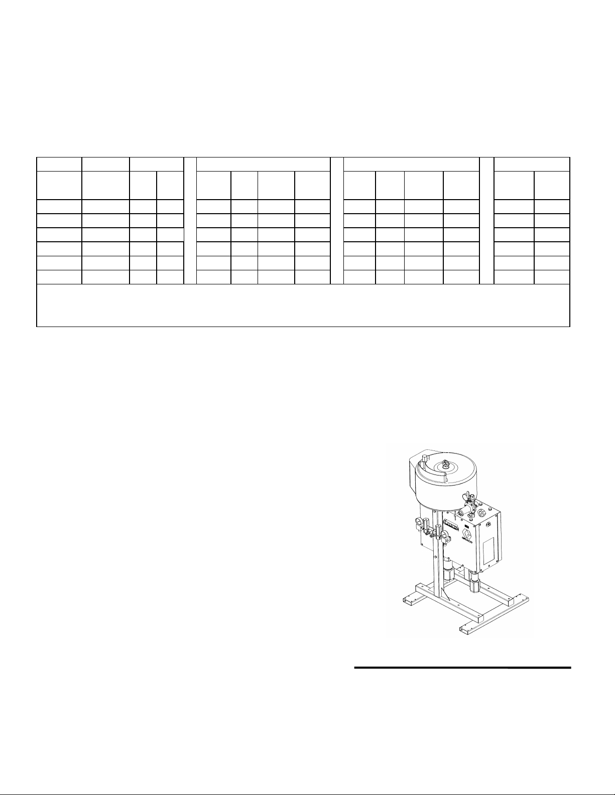
The following chart gives specifications for the Hydra-Cat
H.P. pumps, usin
No. 10 weight oil. The volumetric ratio
is expressed as the proportion of the volume of fluid of the
primary pump compared to the volume of fluid of the
secondary pump.
Ratio At Minimum Ratio Settin
Air Motor AssemblyMin Max Stall StallOutputOutput Stall Stall
Part No. PSI Bar GPM LPM PSI Bar GPM LPM DF DF
Premier
Premier
Kin
Kin
Kin
Note: All Output Pressures Limited To 5000 PSI By Integral Pressure Relief Valves
Note: Pressure outputs calculated at 100 PSI Air Pressure for Premier and 90 PSI Air Pressure for King
Note: Volume outputs calculated at 40 cycles per minute.
11.504.
477 1.
4444
42 21
1131
74.617.
.1 23.
For example, Model 965477 has a minimum volumetric
ratio of 1:1. At this settin
pumps combined will deliver an output of 3.0
maximum volumetric ratio for Model 965477 is 3:1 and the
combined output at that setting is 2.0 gpm.
At Maximum Ratio Settin
14.4 727
714
11.
14.4 41482
22.810.
2157
the primary and secondary
pm. The
Lower ID
utputOutput Master Slave
.4 12
7.7
.1 19.2 1
Installation
The Typical Installation shown is only a guide to setting up
the complete Hydra-Cat H.P. system. For assistance in
ning a system to suit your particular needs, contact
desi
your nearest Graco representative.
NOTE: The reference numbers and letters in the text
correspond to the numbers and letters in the drawings.
Location
Sit the proportioner on a flat floor surface.
Connect the Fluid Supply Lines
Connect the grounded fluid hoses to the pump inlet fittings
(P, R). If the unit will be pressure fed from separate supply
units, install a fluid pressure gauge at each inlet.
NOTE: The pressurized fluid supplies must not exceed 1/4
of the operatin
that level will feed ri
rationing will result.
fluid pressure of the pump. Pressure above
ht through the pump and improper
Connect the Fluid Output Lines
Connect electronically conductive fluid hoses to the pump
outlet fittings. Tighten all of the fittings.
Fig. 1
6 684025
Page 7
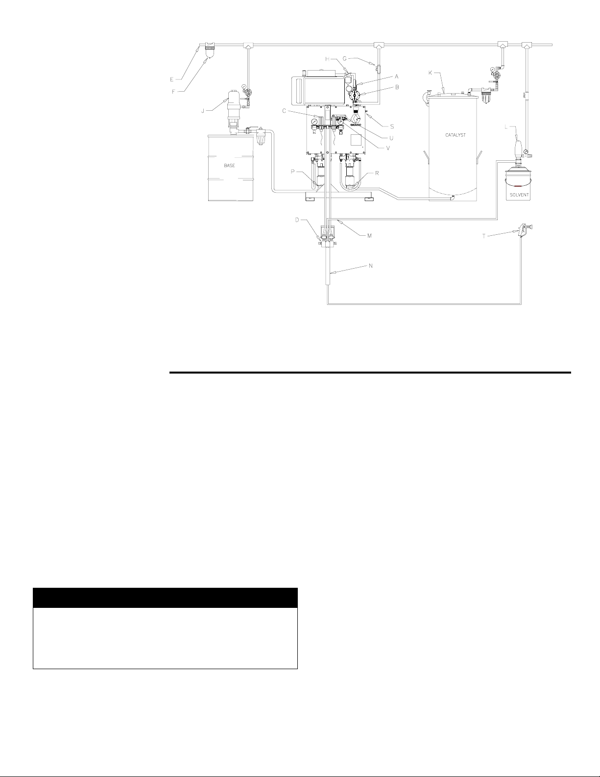
KEY
g
g
g
g
g
g
A Bleeder Type
Main Air Valve
B Air Regulator
C Pressure Relief
Valve
D Mix Manifold
E Air Supply Line
F Air Line Filter
G Air Shutoff Valve
H Air Line Lubricator
J Base Supply Pump
K Catalyst Supply
Pressure Pot
L Solvent Supply
Pump
M Mix Manifold Flush
Inlet
N Static Mixer
P Primary Pump Inlet
R Secondary Pump
Inlet
S Ratio Adjustment
Screw
T Spray Gun
U Ratio Indicator Plate
V Ratio Indicator Pin
Fig. 2 Typical Installation
System Accessories Connect the Air Supply Line
Refer to Fig. 2.
NOTE:
To ensure the maximum pump performance and
safety, be sure that all the accessories used are properly
sized to meet your system requirements and the pressure
limits of the pump. Use only
enuine Graco parts and
accessories.
Connect an electrically conductive air supply hose to the
3/4” npt(f) port of the air manifold (B). Open the bleed-type
master air valve (A) and, usin
ulator (B) to the desired pressure. See the Typical
air re
Installation and the Parts Drawing.
Pressure Relief Valve
In the air line, install an air filter (F) to remove harmful dirt
and moisture from the compressed air supply. Install an air
line lubricator (H) downstream from the air filter, the air
ulator (B) and the bleed-type master air valve (A). A
re
lubricator will provide automatic lubrication to the air motor.
All components have rated working pressures of 5000 psi
(345 bar) or
reater. For more information about the
pressure relief valve, see instruction manual 308547.
WARNING
A bleed-type master air valve (A) is required in your
system to relieve the air trapped between the valve and
the pump after the pump is shut off. Trapped air can
cause the pump to cycle unexpectedly, resultin
possible serious injury, including amputation.
in
the pressure gauge, set the
684025 7
Page 8

Electrical Grounding
g
g
g
g
g
g
g
g
g
g
g
g
g
WARNING
4.
Spray gun or dispensing valve:
h connection to a properly grounded fluid hose
throu
and pump.
Obtain grounding
FIRE AND EXPLOSION HAZARD
Static electricity is created by the hi
flow of fluid throu
system is not properly
occur and the system may become hazardous.
To reduce the risk of static sparkin
result in a fire or explosion and cause serious
injury, follow these recommendations for
providin
system.
Also, read the WARNING section, FIRE AND
EXPLOSION HAZARD on page 4.
1.
Pump:
Loosen the grounding lug locknut (A) and
washer. Insert one end of a 12
round wire (B) into the slot in the lug (C). Tighten the
locknut securely. See Fi
round wire to a true earth ground. Order a
the
Groundin
P/N 208950, (25 feet (7.6 m) long, 12 ga.).
Air and fluid hoses:
2.
hoses with a maximum of 500 feet (150 m) combined
hose length to ensure grounding continuity.
Air compressor:
3.
manufacturer’s recommendations
electrical continuity throughout your
Clamp, P/N 103538, and a Grounding Wire,
follow the air compressor
h the pump and hose. If your
rounded, sparking may
which can
a (1.5 m2) minimum
. 3. Connect the other end of
Use only electrically conductive
h velocity
Fluid supply container:
5.
Object being sprayed:
6.
All solvent pails
7.
code.
placed on a positively
the pail on a non-conductive surface, such as paper or
cardboard, which interrupts the grounding continuity.
To maintain grounding continuity when flushing or
8.
Use only metal pails
relieving pressure,
or dispensin
metal pail, then trigger the gun.
valve firmly to the side of a grounded
according to your local code.
according to local code.
used when flushing, according to local
which are conductive,
rounded surface. Do not place
always hold a metal part of the gun
B
A
Fig.3
C
0720
8 684025
Page 9

Ratio Adjustment
g
Understanding the terms used with the Hydra–Cat (H.P.)
System, how it functions, and how to find and set the
correct ratios for your application is the key to easier, more
versatile operation of your proportional system.
Be sure to read and understand the followin
before operating the equipment.
information
Terms
Ratio refers to the simultaneous output of a certain volume
of fluid by the primary and secondary pumps.
Key
A Primary Pump
B Secondary Pump
C Ratio Adjustment Screw
D Wet Cups
E Fulcrum and Arm
F Primary Pump Output
G Secondary Pump Output
The primary pump (A) is directly under the air motor (H);
it usually pumps the base fluid. The secondary pump (B)
is on the opposite end of the lever arm (E); it usually
pumps the catalyst. The ratio of the secondary pump(s)
can be changed by adjusting the ratio adjustment screw
(C). See Fig. 4.
There are three main steps when applying the use of ratios:
(1) determine the ratio that is required, (2) calculate the
ratio setting, and (3) set the ratio on the Hydra-Cat H.P.
system.
H Air Motor
I Air Input
J Bleed Type Master Air Valve
Fig. 4
684025 9
Page 10

Determine the Ratio
g
g
g
g
g
g
g
g
g
g
Set the ratio based on your situation. If :
• The fluids are supplied at a ready–to–spray
viscosity, simply set the ratio as explained under
Adjusting the Ratio.
• The fluids are NOT supplied at ready–to–spray
viscosity, the ratio must be determined after the
reducer is added to the base, as instructed in
Procedure 1, below.
NOTE: Evaporation of the reducer in the base causes
es in the ratio. To prevent evaporation, store
chan
the base in a closed container.
NOTE: Some reducers have very little ability to lubricate
and many cause seals to dry out. To prolon
seal life, be sure your pump seals are compatible
with the base’s reducer. Contact your Graco
representative for the correct seals to use.
the
Procedure 1: Base is not pre-reduced
When adding the reducer to the base before proportionin
with the VRHC system, determine the ratio of the
base/reducer mixture to the catalyst in order to set the
proper ratio.
Example:
The instructions on the can say “Mix 5 parts base to 1 part
catalyst. Then reduce 3 parts of this mixture to 1 part
reducer.”
1. Add the parts of the base and catalyst to find the parts
mixture.
5 parts base
+ 1 parts catalyst
6 parts mixture
2. The next statement on the can says, “Reduce 3 parts of
the mixture.” So divide the parts of the mixture by 3 parts
to reduce to find the parts reducer.
6 parts mixture
/ 3 parts to reduce
2 parts reducer
3. To determine the ratio of the secondary pump, add the
appropriate parts of base and reducer to find the parts
combined base/reducer.
5 parts base
+ 2 parts reducer
7 parts combined base/reducer to
1 part catalyst
The ratio of the pump is 7:1.
Relationship Between the Primary and
Secondary Pumps
Moving the fulcrum point away from the primary pump
reduces the secondary stroke len
output. Movin
increases the secondary stroke len
output.
. 5 shows the relationship between the primary pump
Fi
and the secondary pump.
the fulcrum point closer to the primary pump
th, reducing its fluid
th, increasing its fluid
Adjusting the Ratio
See Fig. 2. Use a wrench to rotate the ratio adjustment
screw (S). Rotatin
ratio. Rotatin
the ratio. The indicator pin (V) will move alon
indicator scale (U) as the ratio adjustment screw is rotated.
When the pin is above the desired ratio, remove the
wrench and perform a ratio test as described on page 12.
the screw clockwise will increase the
the screw counterclockwise will decrease
the ratio
Fig. 5
10 684025
Page 11

Operation
g
g
g
g
g
g
g
g
g
g
gg
g
g
WARNING
INJECTION HAZARD
The system pressure must be manually
relieved to prevent the system from starting or
sprayin
pressure can be injected through the skin and
cause serious injury. To reduce the risk of an
injury from injection. To reduce the risk of
parts, follow the Pressure Relief Procedure
whenever you:
• are instructed to relieve the pressure,
• stop spraying,
• check or service any of the system
• or install or clean the spray tips.
Pressure Relief Procedure
1. Lock the spray gun’s trigger safety.
2. Shut off ALL fluid supplies to the pump.
accidentally. Fluid under high
equipment,
System Flushing
The pumps were tested with li
Before operating the pump, thoroughly flush the Hydra-Cat
H.P. to prevent contamination of your fluids.
NOTE:
Flush the mixer, hose and
fluid from reactin
manufacturer for the effective pot life of the fluid you are
using.
1. Put the pump intake hoses into a 5
container of a compatible solvent. Refer to the fluid
manufacturer’s recommendations.
2. Start the pump as explained below.
3. Do not install a spray tip yet. Hold a metal part of the
un firmly to the side of a grounded metal pail. Usin
the lowest possible air pressure to the air motor that
will activate the pump, trigger the gun into the pail.
4. When clean solvent comes from the spray
release the trigger and carefully check all connections
in the system for leaks.
5. Take the hoses out of the solvent, and trigger the gun
until all the solvent has been pumped out of the hoses.
Immediately turn off the bleeder-type master air valve.
or curing in them. Contact your fluid
htweight oil at the factory.
un often enough to prevent
allon (20 liter)
un,
3. Close the bleed-type master air valve.
4. Unlock the spray gun’s trigger safety.
5. Hold a metal part of the spray gun firmly to the side
of a grounded metal pail. Trigger the spray gun into
the pail to relieve pressure.
6. Lock the spray gun’s trigger safety.
7. Open the sampling valves, having a container ready
to catch the drainage.
8. If you suspect that the spray tip or nozzle or the
hose is completely clogged or that pressure has not
been fully relieved after followin
follow this procedure: Very slowly loosen the tip
guard retaining nut or hose end coupling and relieve
pressure
clear the obstruction.
radually, then loosen completely. Now
the steps above,
Start the Pump
1. Close the bleed-type master air valve, and turn the air
regulator knob all the way out (counterclockwise).
2. Turn on the main air supply.
3. With the mixer manifold handle in the open position,
er the gun, slowly open the bleed-type master air
tri
valve, and turn the air re
the pump starts.
4. Allow the pump to cycle slowly until all the air is pushed
out of the lines. Release the trigger. The pump will stall
against the pressure.
5. The manifold handle controls fluid flow. With the lever
of the manifold in the open (down) position, base and
catalyst are supplied to the
move the handle to the closed (up) position.
ulator knob clockwise until
un. To stop the flow,
Standard Operating Flushing
Use the solvent valves to flush contaminants and mixed
fluids from the mixer manifold, hose and spray gun. Follow
the procedure provided with the mix manifold assembly.
684025 11
Page 12

Checking the Ratio
g
g
g
g
g
g
g
g
g
g
g
g
g
g
g
g
g
g
g
g
g
g
g
Note: The mix ratio must be checked at the normal
operatin
manifolds provide a means for checkin
that includes needle valves for adjustin
pressure during the test. The following procedure is
an example of how to properly check the mix ratio.
1. Open the mixer manifold and trigger your spray gun.
2. Set your operatin
operatin
engage the safety latch.
3. Close the mixer manifold inlet valves.
4. Sli
5. Place a
htly open the sampling valve on the secondary
pump side. Sli
primary pump side. This will prevent pressure from
buildin
valve to open.
valve.
fluid pressure of the pump. Most mixer
mix ratio
the fluid
pressure. After determining the
pressure, release the spray gun trigger and
htly open the sampling valve on the
up on the secondary pump, causing the relief
rounded waste container under the samplin
6. Open the mixer manifold. Use the sampling valves to
adjust the pressures to your
normal operatin
pressures.
7. Close the mixer manifold. Put the samplin
containers under the sampling valves.
8. Open the mixer manifold. Check the ratio; make sure
the pressure is within 20% of your normal operatin
pressure. Close the mixer manifold when enough
fluid has been dispensed into the samplin
containers.
NOTE: If the pressure readings are not within 20% of
your normal operatin
flushin
sample a
there is a problem with the sampling valves, ratio
settin
setting or service the sampling valves or pump.
procedure on page 11, then take a
ain. If your sample ratio is incorrect,
, or pump operation. Check the ratio
pressure, follow the
Maintenance
Pump Lubrication
Wet Cups
Each of the fluid cylinders has a wet cup (18) at the top
that must be kept lubricated. See figure 6. The wet cups
should be inspected and filled on a weekly basis, or
more frequently if found to be dry. To inspect the wet
cups, follow the pressure relief procedure on page 11.
WARNING WARNING
To reduce the risk of serious injury whenever you are
instructed to relieve pressure, always follow the Pressure
Relief Procedure on page 11.
With the bleeder type main air valve (1) turned off,
remove the thumb screws (14) and the two guards (15)
from the sides of the proportioner. The wet cups (18)
should be filled to 1/3 full with Graco Throat Seal Liquid
(TSL) or compatible solvent.
The packing nuts (19) are torqued at the factory and are
ready for operation. If one becomes loose and there is
leaking from the throat packings, relieve the pressure,
then torque the nut to 136–149 N.m (100–110 ft-lb)
the supplied wrench (20). Do this whenever
usin
necessary. Do not over tighten the packing nut.
Bearings
Many of the bearing surfaces on the proportioner are
permanently lubricated or are self lubricating. There are
four main bearings (21) on the lever arm
lubricated
is every six months in single shift operation. To lubricate
the bearin
page 11.
To reduce the risk of serious injury whenever you are
instructed to relieve pressure, always follow the Pressure
Relief Procedure on page 11.
With the bleeder type main air valve turned off, remove
the twenty hex bolts (16) with a 13mm wrench or socket
and then remove the four sheet metal covers (17) from
the front and back of the proportioner.
The left rear cover may contain a sensor attached to a
cable. Do not remove the sensor, but carefully set the
cover to the side without strainin
sensor or cable. The four main bearin
exposed. Use the adapter (205532) provided to grease all
four bearin
sufficient.
on a regular interval. The lubrication interval
s, follow the pressure relief procedure on
s. One or two squirts (2-3 cc) will be
that must be
or damaging the
s (21) are now
12 684025
Page 13

Air Lubrication
g
g
g
Make sure to use an Industrial Grade 1, Heavy Duty,
Extreme Pressure, Lithium Soap Grease, Graco Part
Number 110293 or equivalent.
If your air supply Is very dry, install an air line lubricator
between the air re
ulator and the pump air motor for
automatic lubrication. Refer to the air motor manual for
.
details
Replace the covers (17) and the bolts (16) after
and before startin
the machine. The covers (17) are
reasing,
safety guards and must be in place when the proportioner
is in operation.
Fig. 6
KEY
1 BLEEDER TYPE MAIN AIR VALVE 13 ROD ADAPTER
2 AIR MOTOR 14 THUMB SCREWS
3 PRIMARY CYLINDER 15 GUARDS
4 SECONDARY CYLINDER 16 HEX BOLTS
5 FRAME 17 COVERS
6 AIR MOTOR TIE RODS 18 WET CUPS
7 FLUID CYLINDER TIE RODS 19 PACKING NUTS
8 TIE ROD NUTS 20 PACKING NUT WRENCH
9 CONNECTING ROD NUT, AIR MOTOR 21 MAIN BEARINGS
10 CONNECTING ROD NUT, PRIMARY 22 SNAP RING
11 CONNECTING ROD NUT, SECONDARY 23 FLUID OUTLET, PRIMARY
12 COUPLING COLLARS 24 FLUID OUTLET, SECONDARY
684025 13
Page 14

Troubleshooting
g
gaug
g
g
g
g
g
g
g
g
gaug
g
g
g
g
g
g
gaug
g
g
g
g
Troubleshooting Techniques
Because the pumps are mechanically linked, the action of
one pump can affect the readin
Therefore, the key to successful troubleshooting is to be
sure to isolate the problem.
For example, if the secondary pump pressure, as read on
the
chan
pump. To isolate the problem:
1. Relieve the pressure.
2. With the sampling valves still open, set the air supply
e, is low and sluggish during the pump
eover. The most likely problem is a binding primary
regulator to the lowest setting and open the bleedtype main air valve (1). Refer to fi
the re
move. Notice the position of the secondary pump
(11). Turn off the bleeder-type main air valve (1) so
that the secondary pump rod is at its lowest position
when the pump stops.
ulator setting until the pump just begins to
s of the second pump.
ure 6. Increase
WARNING WARNING
To reduce the risk of a serious injury, always follow the
Pressure Relief Procedure on page 11 whenever you
are instructed to relieve the pressure.
3. With the main bleed-type air valve (1) off, remove
the thumb screws (14) and
side of the proportioner.
4. Unscrew the connectin
secondary pump. Now you can verify the operation
of the primary pump alone.
uards (15) from each
rod nut (11) from the
8. With the main bleed-type air valve (1) off, remove
the thumb screws (14) and
side of the proportioner.
9. Unscrew the connectin
primary pump. Now you can verify the operation of
the secondary pump alone.
Reinstall the
proportioner. Turn the main air valve (1) back on
and carefully increase the air pressure.
10. Using the sampling valves at the mixer manifold:
A. Open and close the samplin
for pump stallin
strokes.
B. Check for rapid
pump changeover
11. When the operation of the secondary side has been
verified, reconnect the connectin
primary pump.
Use very low air pressure to the air motor when
troubleshootin
very high fluid pressure, which can cause serious injury,
includin
and injury from moving parts.
To reduce the risk of a serious injury, always follow the
Pressure Relief Procedure on page 11 if the problem
you are checking does not require air.
injection, splashing in the eyes or on the skin,
uards (15) on both sides of the
on both the up and down
the system. This system can produce
uards (15) from each
rod nut (10) from the
valves and check
e response during the
rod (10) of the
Reinstall the guards (15) on both sides of the
proportioner. Turn the main air valve (1) back on
and carefully increase the air pressure.
5. Using the sampling valves at the mixer manifold:
A. Open and close the sampling valves and check
for pump stallin
strokes.
B. Check for rapid
pump changeover
6. When the operation of the primary side has been
verified, reconnect the connectin
secondary.
7. With the sampling valves still open, set the air supply
regulator to the lowest setting and open the bleedtype main air valve (1). Increase the regulator setting
until the pump just be
position of the primary pump. Turn off the bleedertype main air valve (1) so that the primary pump rod
(10) is at its lowest position when the pump stops.
on both the up and down
e response during the
rod (11) of the
ins to move. Notice the
WARNING
To reduce the risk of injurin
ers, or other body parts, never place your hands,
fin
body or tools inside the safety panels for any reason
while the unit is operating.
or amputating your hands,
14 684025
Page 15

Troubleshooting Chart
g
g
g
g
g
g
g
g
g
PROBLEM CAUSE SOLUTION
System will not run or
stops while running.
The fluid pressure
bounces significantly
(>500 psi) while pump is
running
Mix ratio test is
significantly different from
the mix ratio setting.
Spray output is spitting Running out of one
A squeaking or knocking
noise is heard.
The proportioner speeds
up or runs erratically
Air pressure or air
volume is too low.
The fluid valves or
hoses are closed or
restricted.
The air motor is
worn or damaged.
The displacement
cylinder(s) is
damaged or has
seized
Air volume is too
low.
Feed pump
pressure is too
high.
The displacement
cylinder(s) check
valves are not
seating.
Mix ratio test was
not performed at
the normal
operating pressure
of the pump
Running out of one
material.
The displacement
cylinder(s) are worn
or the check valves
are not seating.
material.
Siphon hoses are
leaking in air.
The bearings are
dry or worn.
Running out of one
material.
The cylinders are
worn or damaged.
Increase air pressure. Check air compressor and air supply filters
ulator, lubricator valves and other components for blockages
re
and restrictions. If this is a new system, be sure that air supply
components have been sized properly.
Check the
ulators, valves and other fluid line components for blockages
re
and restrictions. If this is a new system, be sure that the fluid
components have been sized properly.
Service the air motor. See “servicing the Air Motor” on page 17.
See troubleshootin
cylinder. See “Service the cylinders” on page 16.
Verify that air pressure at the air motor inlet is not droppin
pump changeover. Check air compressor and air supply filters
regulator, lubricator valves and other components for blockages and
restrictions. If this is a new system, be sure that air supply
components have been sized properly. 1” NPT hoses, fittin
accessories are required to provide the necessary air volume.
Reduce feed pump pressure. Feed pump pressures must be less
than 25% of proportioner output pressure.
See troubleshootin
cylinder. See “Service the cylinders” on page 16.
Perform ratio test again following ratio test procedure on page 12.
Check and refill material reservoirs. Repeat the test after the air has
been removed from the system.
See troubleshootin
cylinder(s). See “Service the cylinders” on page 16.
Check and refill material reservoirs. Remember that once air is in
the fluid system it may take a while for all of it to escape..
Tighten and seal all siphon fittings on proportioning pump and feed
pumps.
Lubricate the bearings or replace them if required. See “service the
bearings” on page 18.
Check and refill material reservoirs.
See troubleshooting techniques below to isolate the problem
cylinder(s). See “Service the cylinders” on page 16.
un, fluid hoses, mix manifold, static mixer, fluid filters,
techniques below to isolate the problem
durin
s and
techniques below to isolate the problem
techniques below to isolate the problem
684025 15
Page 16

Service
g
g
g
g
g
g
g
g
g
Required Tools
• Set of large adjustable wrenches
• Set of metric sockets or wrenches
• Large pipe wrench
• Torque wrench
• Rubber mallet
• Flat end punch
WARNING CAUTION
To reduce the risk of serious injury or amputation,
carefully follow all instructions listed below. In addition,
be sure that the pressure relief procedure has been
completed and that the main bleeder-type air valve has
been turned off and locked out before removin
guards or covers from the proportioner.
ANY
Disconnecting the Displacement Pump(s)
1. Flush the System. Follow the procedure on page
11.
Relieve the pressure.
2.
WARNING
To reduce the risk of serious injury whenever you are
instructed to relieve pressure, always follow the Pressure
Relief Procedure on page 11.
3. Disconnect the siphon hose and the fluid outlet hose.
4. With the bleeder type main air valve turned off (1),
remove the thumb screws (14) and the two
(15) from the sides of the proportioner.
5. Disconnect the displacement pump (3) from the frame
(5) as follows:
6. Note the relative position of the pump’s fluid outlet (23)
to the frame and also note the frame location of
displacement pump bein
displacement pump must be returned to its ori
position and orientation.
Be sure to use two people when liftin
disconnecting the pump. This pump is too heavy for one
person. Be sure to support the displacement pump while
it is bein
causin
bracing the pump, or by having at least two people hold it
while another disconnects it.
7. Using an adjustable wrench (or hammer and punch),
unscrew the couplin
(13). Do not lose or drop the couplin
Fig. 6.
8. Hold the tie rod flats with a wrench to keep the rods
from turning. Unscrew the nuts (8) from the tie rods
(7). Carefully remove the displacement pump (3)
from the frame.
9. Refer to the separate manual supplied for
disconnected, to prevent it from falling and
injury or property damage. Do this by securely
nut (10,11) from the rod adapter
displacement pump service. Some models use two
different displacement pumps. Be sure to look at the
model number and use the appropriate manual for
service and reference.
removed. Each
, moving, or
collars (12). See
uards
inal
16 684025
Page 17

Reconnecting the Displacement Pump
g
g
g
g
g
g
g
g
g
g
g
g
g
g
g
g
g
g
g
CAUTION
1. Make sure the coupling nut (10,11) and the couplin
collars (12) are in place on the displacement rod. See
Fig. 6.
2. Use at least two people to hold the displacement pump
while another reconnects it to the frame (see the
CAUTION in the removal procedure above).
3. Position and orient the displacement pump (3,4) to the
frame (5) as was noted in step 6 under Disconnectin
the Displacement Pump.
4. Position the displacement pump (3,4) on the tie rods
(7).
5. Screw the nuts (8) onto the tie rods (7) and torque to
81–89 N.m (60–66 ft-lb).
6. Screw the couplin
loosely. Hold the rod adapter flats with a wrench to
keep it from turnin
tighten the coupling nut. Torque to 196–210 N.m ft-lb).
7. Fill the wet cup (18) 1/3 full with Graco Throat Seal
Lubricant or compatible solvent.
8. Reconnect all hoses.
9. Replace the two
(14) from the sides of the proportioner.
10. Turn on the air supply. Follow the procedure for
startin
first to ensure proper operation.
the pump on page 11. Run the pump slowly at
nut (10) onto the rod adapter (13)
. Use an adjustable wrench to
uards (15) and the thumb screws
Be sure to use an overhead hoist when lifting, moving or
disconnectin
lbs. and is too heavy for one person to handle. A lift ring
is provided on the motor for this purpose.
5. Note the relative position of the air motor’s air
connection to the frame. The air motor must be
returned to its original orientation.
6. Usin
unscrew the couplin
(13). Do not lose or drop the coupling collars (12). See
Fig. 6.
7. Hold the tie rod flats with a wrench to keep the rods
from turnin
(6). Carefully remove the air motor (2) from the frame.
8. Refer to the separate manual supplied for air motor
service. Be sure to look at the model number stamped
on the air motor and use the appropriate manual for
service and reference.
Reconnecting the Air Motor
1. If the connectin
Motor Stud as a part of servicin
thread adhesive when reinstallin
on to the Air Motor Stud.
2. Make sure the couplin
collars (12) are in place on the rod adapter (13).
the air motor. This air motor weighs 145
an adjustable wrench (or hammer and punch),
nut (9) from the rod adapter
. Unscrew the nuts (8) from the tie rods
rod has been removed from the Air
, be sure to use
the connecting rod
nut (9) and the couplin
WARNING
To reduce the risk of serious injury whenever you are
instructed to relieve pressure, always follow the Pressure
Relief Procedure on page 11.
11. Before returning the pump to production, relieve the
pressure and re-torque the packing nut (2) to 136–
149 N.m (100–110 ft-lb). The must be performed
after the pump has been cycled a number of times
Disconnecting the Air Motor
1. Relieve the pressure.
WARNING
To reduce the risk of serious injury whenever you are
instructed to relieve pressure, always follow the Pressure
Relief Procedure on page 11.
2. With the bleeder type main air valve turned off,
disconnect the air hose from the air motor.
3. Remove the thumb screws (14) and the two
(15) from the sides of the proportioner.
4. Disconnect the air motor (2) from the frame (5) as
follows:
uards
3. Use an overhead hoist to position the air motor on the
frame in the same orientation as noted in step 5 of
disconnecting the air motor. (see the CAUTION in the
removal procedure above).
4. Position the air motor (2) on the tie rods (6).
5. Screw the nuts (8) onto the tie rods (6) and torque to
81–89 N.m (60–66 ft-lb).
6. Screw the couplin
loosely. Hold the rod adapter flats with a wrench to
keep it from turnin
tighten the coupling nut. Torque to 196–210 N.m ft-lb).
7. Reconnect the air hose
8. Replace the two guards (15) and the thumb screws
(14) onto the sides of the proportioner.
9. Turn on the air supply. Follow the procedure for startin
the pump on page 11. Run the pump slowly at first to
ensure proper operation
nut (9) onto the rod adapter (13)
. Use an adjustable wrench to
684025 17
Page 18

Replacing the Bearings
g
ging
g
g
g
g
g
g
g
g
g
g
g
g
g
g
g
g
g
g
g
g
g
g
g
g
g
1. Relieve the Pressure. Refer to Figure 6 and Figure 7.
WARNING
To reduce the risk of serious injury whenever you are
instructed to relieve pressure, always follow the Pressure
Relief Procedure on page 11.
2. With the bleeder type main air valve (1) turned off,
remove the twenty hex bolts (16) with a 13mm wrench
or socket and then remove the four sheet metal
covers (17) from the front and back of the
proportioner. The left rear cover may contain a sensor
attached to a cable. Do not remove the sensor, but
carefully set the cover to the side without strainin
dama
bearings (21) are now exposed.
3. Remove the thumb screws (14) and the two
(15) from the sides of the proportioner.
4. Usin
unscrew the couplin
the rod adapters (13) on the two displacement pumps
and the air motor. Do not lose or drop the couplin
collars (12). See Fig. 6.
5. The left rear bearin
end. Remove the ma
Use a snap rin
(22) from the shafts and remove the retainin
washers.
6. You should now be able to slide the bearin
of the shaft ends.
7. Replace the bearin
replacement parts. Pack the bearin
Grade 1, Heavy Duty, Extreme Pressure, Lithium
Soap Grease, Graco Part Number 110293 or
equivalent.
the sensor or cable. The (4) four main
an adjustable wrench (or hammer and punch),
nuts (10, 11, 12) from each of
shaft has a magnet stuck on its
net and put it in a safe place.
pliers to remove the four snap rings
s only with identical Graco
s in Industrial
or
uards
s (21) off
8. Re-install the new bearin
so may require slightly shifting the shaft
Doin
assembly which may have dropped durin
removal.
9. Re-install the four retainin
rings (22).
10. Replace the ma
bearing shaft.
11. Make sure the couplin
couplin
adapters.
12. Screw all three (3) couplin
the rod adapters (13) loosely. Hold each rod
adapters flats with a wrench to keep it from turnin
Use an adjustable wrench to ti
nuts. Torque to 196–210 N.m ft-lb).
13. Replace the covers (17) and the bolts (16).
14. Replace the two
(14) onto the sides of the proportioner.
15. Turn on the air supply. Follow the procedure for
startin
slowly at first to ensure proper operation.
collars (12) are in place on all three rod
the pump on page (11). Run the pump
net onto the end of the left rear
uards (15) and the thumb screws
s (21) onto the shafts.
bearin
washers and their snap
nuts (10, 11, 12) and the
nuts (10, 11, 12) onto
hten the couplin
.
18 684025
Fig. 7
Bearing Inset
Page 19

Dimensions
(A) Height.......................................... 66.0 inch 1676 mm)
(B) Length.......................................... 31.5 inch (800 mm)
(C) Width ...........................................33.0 inch (838 mm)
(D) Air Inlet..........................................................3/4 npt(f)
(E) Fluid Inlets..............................................Two, 2” npt(f)
(G) Fluid Outlet ..........................................Two 1/2” npt(f)
(H) Relief Valve Outlets ........................... Two, 1/4 npt(m)
Net Weight....................................... 700 pounds (320 kg)
A
B
C
Premier Air Consumption
At 40 PSI (2.8 bar)
CFM M
13 0.36 20 0.56 26 0.74 5
25 0.71 40 1.13 52 1.48 10
38 1.07 60 1.69 78 2.22 15
50 1.42 80 2.26 104 2.95 20
63 1.78 100 2.82 130 3.69 25
75 2.13 120 3.39 156 4.43 30
88 2.49 140 3.95 183 5.17 35
100 2.84 160 4.52 209 5.91 40
3
/min
At 70 PSI (4.9 bar)
CFM M3/min
At 100 PSI (7.0 bar)
CFM M3/min
At cycles
per min
King Air Consumption
At 40 PSI (2.8 bar)
CFM M
8 0.23 13 0.36 15 0.43 5
16 0.45 25 0.72 31 0.87 10
24 0.68 38 1.07 46 1.30 15
32 0.90 51 1.43 61 1.74 20
40 1.13 63 1.79 77 2.17 25
48 1.35 76 2.15 92 2.61 30
56 1.58 88 2.51 107 3.04 35
64 1.80 101 2.86 123 3.48 40
3
/min
At 70 PSI (4.9 bar)
CFM M3/min
At 100 PSI (7.0 bar)
CFM M3/min
At cycles
per min
684025 19
Page 20

NOTES
20 684025
Page 21

Technical Data
Air motor effective diameter ....................................................................................Premier 12.64” (321 mm)
............................................................................................................................ King 10.00” (254 mm)
Air motor stroke ...................................................................................................................... 4.75” (120 mm)
Operating air pressure range 20 to 100 psi (1.4 to 7 bar)
Recommended pump speed ......................................................................... 40 cycles per minute maximum
Maximum fluid inlet pressure ....................................................................... 25% of Output or 1000 psi max.
Maximum pump operating temperature ..................................................................................... 180°F (82°C)
Wetted parts:
Carbon Steel Models
Primary and secondary displacement pumps ................... Carbon Steel; Chrome Steel; Alloy Steel;
Chrome, Zinc, and Nickel Plating; 550 and 17-4 PH Grades of Stainless Steel;
Ductile Iron; Tungsten Carbide; PTFE
Stainless Steel Models
Primary and secondary displacement pumps ...... 316, 440 and 17-4 PH Grades of Stainless Steel;
Tungsten Carbide; PTFE; Glass-Filled PTFE; Leather
All Models
Fluid hoses ................................................................................... Nylon, Zinc-plated steel couplings
Pressure relief valves ..................................................... 304 Stainless Steel, Graphite-filled PTFE
Premier Noise level at 90 psi (6.3 bar) inlet air and at 40 cpm maximum load ..........................86 dB(A)
Glass-Filled PTFE;
Tungsten carbide (Nickel binder)
Leather
King Noise level at 90 psi (6.3 bar) inlet air and 15 cpm maximum load................. 90.5 dB(A) Pressure
97.7 dB(A) Power
684025 21
Page 22

Graco Standard Warranty
WARRANTY
Graco warrants all equipment manufactured by it and bearing its name to be free from defects in
material and workmanship on the date of sale by an authorized Graco distributor to the original
purchaser for use. As purchaser’s sole remedy for breach of this warranty, Graco will, for a period of
twelve months or two thousand hours of operation from time of sale, repair or replace any part of the
equipment proven defective. This warranty applies only when the equipment is installed, operated and
maintained in accordance with Graco’s written recommendations.
This warranty does not cover, and Graco shall not be liable for, any malfunction, damage or wear
caused by faulty installation, misapplication, abrasion, corrosion, inadequate or improper maintenance,
negligence, accident, tampering, or substitution of non-Graco component parts. Nor shall Graco be
liable for malfunction, damage or wear caused by the incompatibility with Graco equipment of
structures, accessories, equipment or materials not supplied by Graco, or the improper design,
manufacture, installation, operation or maintenance of structures, accessories, equipment or materials
not supplied by Graco.
This warranty is conditioned upon the prepaid return of the equipment claimed to be defective to an
authorized Graco distributor for verification of the claim. If the claimed defect is verified, Graco will
repair or replace free of charge any defective parts. The equipment will be returned to the original
purchaser transportation prepaid. If inspection of the equipment does not disclose any defect in
material or workmanship, repairs will be made at a reasonable charge, which charges may includes the
costs of parts, labor and transportation.
DISCLAIMERS AND LIMITATIONS
The terms of this warranty constitute purchaser’s sole and exclusive remedy and are in lieu of any other
warranties (express or implied),
particular purpose
, and of any non-contractual liabilities, including production liabilities, based on
including warranty of merchantability or warranty of fitness for a
negligence or strict liability. Every form of liability for direct, special or consequential damages or loss is
expressly excluded and denied. In no case shall Graco’s liability exceed the amount of the purchase
price. Any action for breach of warranty must be brought within two (2) years of the date of sale.
EQUIPMENT NOT COVERED BY GRACO WARRANTY
Graco makes no warranty, and disclaims all implied
particular purpose
, with respect to accessories, equipment, materials, or components sold but not
warranties of merchantability and fitness for a
manufactured by Graco. These items sold, but not manufactured by Graco (such as electric motor,
switches, hose, etc.) are subject to the warranty, if any, of their manufacturer. Graco will provide
purchaser with reasonable assistance in making any claim for breach of these warranties.
Graco Information
FOR TECHNICAL ASSISTANCE
, contact your Graco distributor or call one of the following numbers:
1-800-367-4023
612-623-6921
612-378-3505 Fax
22 684025
Sales Offices:
International Offices:
GRACO INC. P.O. BOX 1441 MINNEAPOLIS, MN 55440-1441
PRINTED IN U.S.A. 684025 Revised 06/2003
Minneapolis, Detroit
Belgium, Korea, Hong Kong, Japan
 Loading...