

Page 1
INSTRUCTIONS–PARTS LIST
This manual contains important
warnings and information.
READ AND KEEP FOR REFERENCE.
INSTRUCTIONS
Series 960
Turbine Spray Guns
50 psi (0.35 MPa, 3.5 bar) Maximum Inlet Fluid Pressure
100 psi (0.7 MPa, 7 bar) Maximum Inlet Air Pressure
308336
Rev. J
First choice when
quality counts.
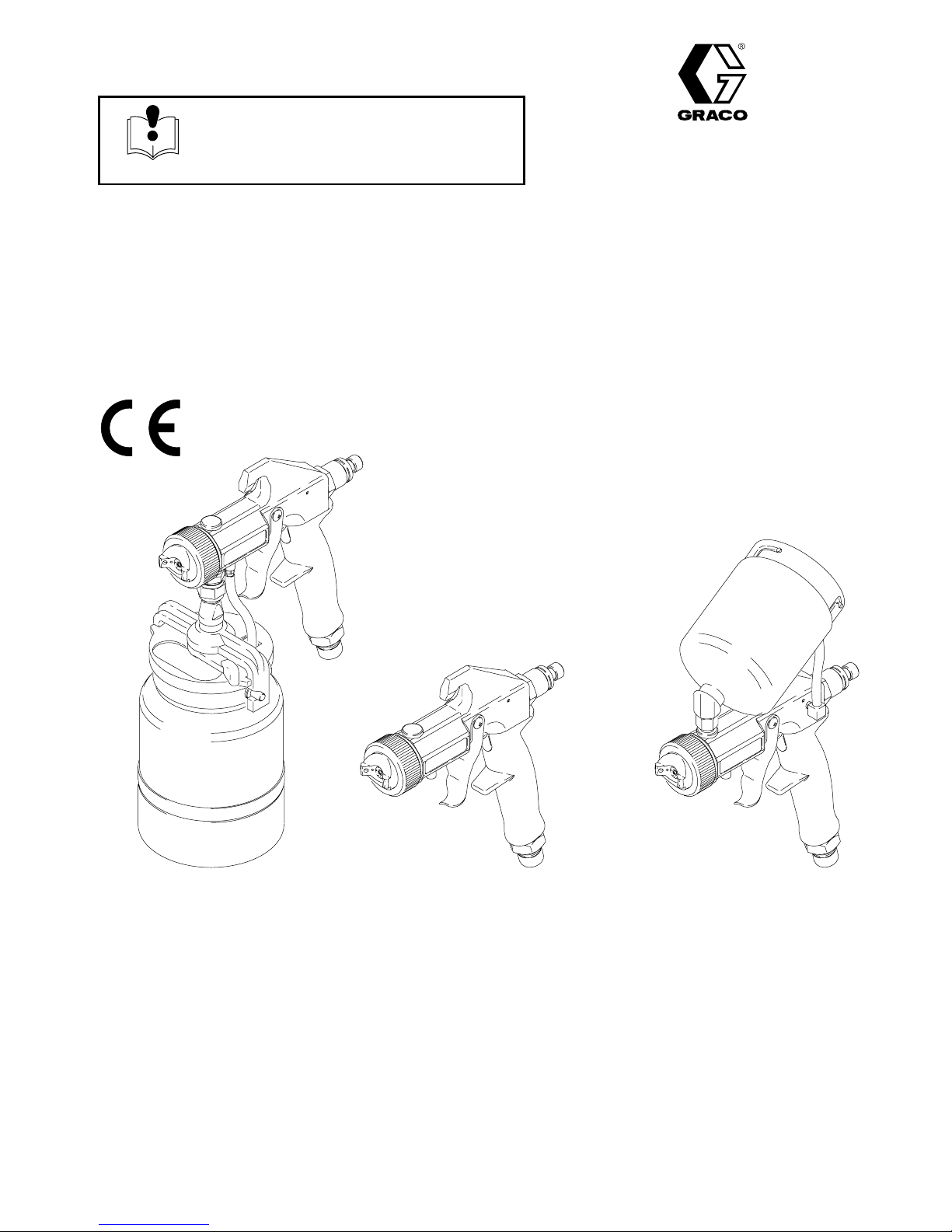
Model 960
Includes 1-quart (1-liter) cup
240080, without fluid set
240083, with #3 fluid set
240084, with #4 fluid set
240085, with #5 fluid set
243920, with 2.0 fluid set
GRACO INC. P.O. BOX 1441 MINNEAPOLIS, MN 55440–1441
Model 960P
240772, without fluid set
240773, with #3 fluid set
243592, with #1 fluid set
COPYRIGHT 1993, GRACO INC.
Graco Inc. is registered to I.S. EN ISO 9001
05292A
Model 960GF.5
Includes 1/2-quart (1/2-liter) cup
240530, without fluid set
Model 960GF.75
Includes 3/4-quart (3/4-liter) cup
240532, without fluid set
Page 2
Table of Contents
Symbols
Warnings 2. . . . . . . . . . . . . . . . . . . . . . . . . . . . . . . . . . . . .
Setup 4. . . . . . . . . . . . . . . . . . . . . . . . . . . . . . . . . . . . . . . . .
Shutdown 12. . . . . . . . . . . . . . . . . . . . . . . . . . . . . . . . . . . .
Spraying Techniques 13. . . . . . . . . . . . . . . . . . . . . . . . . . .
Maintenance 13. . . . . . . . . . . . . . . . . . . . . . . . . . . . . . . . . .
Service 16. . . . . . . . . . . . . . . . . . . . . . . . . . . . . . . . . . . . . .
Troubleshooting 18. . . . . . . . . . . . . . . . . . . . . . . . . . . . . . .
Parts
Model 960 20. . . . . . . . . . . . . . . . . . . . . . . . . . . . . . . .
Models 960GF.5 & 960GF.75 22. . . . . . . . . . . . . . . .
Model 960P 24. . . . . . . . . . . . . . . . . . . . . . . . . . . . . . .
Accessories 25. . . . . . . . . . . . . . . . . . . . . . . . . . . . . . . . . .
Technical Data 25. . . . . . . . . . . . . . . . . . . . . . . . . . . . . . . .
Graco Phone Number 26. . . . . . . . . . . . . . . . . . . . . . . . . .
Warranty 26. . . . . . . . . . . . . . . . . . . . . . . . . . . . . . . . . . . . .
WARNING
WARNING
FIRE AND EXPLOSION HAZARD
Improper grounding, poor ventilation, open flames or sparks can cause a hazardous condition and
result in a fire or explosion and serious injury.
Warning Symbol
WARNING
This symbol alerts you to the possibility of serious
injury or death if you do not follow the instructions.
Caution Symbol
CAUTION
This symbol alerts you to the possibility of damage to
or destruction of equipment if you do not follow the
instructions.
Ground the equipment.
If there is any static sparking or you feel an electric shock while using this equipment, stop
spraying immediately. Do not use the equipment until you identify and correct the problem.
Provide fresh air ventilation to avoid the buildup of flammable fumes from solvents or the fluid
being sprayed.
When flammable liquid is sprayed or used for flushing or cleaning the equipment, the turbine
must be placed at least 20 feet (6.1 m) away from areas where hazardous concentrations of
flammable vapors are likely to occur.
Use additional air hose if necessary to ensure that the turbine is operated in a clean, dry,
well-ventilated area.
Never place the turbine inside a spray booth! Use this equipment outdoors or in extremely
well-ventilated areas.
Keep the spray area free of debris, including solvent, rags, and gasoline.
Electrically disconnect all equipment in the spray area.
Extinguish all open flames or pilot lights in the spray area.
Do not smoke in the spray area.
Do not turn on or off any light switch in the spray area while operating or if fumes are present.
Do not operate a gasoline engine in the spray area.
2 308336
Page 3
INSTRUCTIONS
WARNINGWARNING
EQUIPMENT MISUSE HAZARD
Equipment misuse can cause the equipment to rupture or malfunction and result in serious injury.
This equipment is for professional use only.
Read all instruction manuals, tags, and labels before operating the equipment.
Use the equipment only for its intended purpose. If you are not sure, call your distributor.
Do not alter or modify this equipment. Use only genuine Graco parts and accessories.
Check equipment daily. Repair or replace worn or damaged parts immediately.
Do not exceed the maximum working pressure of the lowest rated system component. See
Technical Data on page 25.
Use fluids and solvents which are compatible with the equipment wetted parts. See Technical
Data on page 25 for this information.
Do not use hoses to pull equipment.
Route hoses away from traffic areas, sharp edges, moving parts, and hot surfaces. Do not
expose Graco hoses to temperatures above 82C (180F) or below –40C (–40F).
Wear hearing protection when operating this equipment.
Do not lift pressurized equipment.
Comply with all applicable local, state, and national fire, electrical, and safety regulations.
Do not point the gun at anyone or at any part of the body.
Follow the Pressure Relief Procedure on page 12 if the fluid nozzle clogs and before cleaning,
checking or servicing the equipment.
Tighten all fluid connections before operating the equipment.
Check the hoses, tubes, and couplings daily. Replace worn or damaged parts immediately.
TOXIC FLUID HAZARD
Hazardous fluid or toxic fumes can cause serious injury or death if splashed in the eyes or on the
skin, inhaled, or swallowed.
Know the specific hazards of the fluid you are using.
Store hazardous fluid in an approved container. Dispose of hazardous fluid according to all local,
state and national guidelines.
Always wear protective eyewear, gloves, clothing and respirator as recommended by the fluid
and solvent manufacturer.
Do not use 1,1,1-trichloroethane, methylene chloride, other halogenated hydrocarbon solvents or
fluids containing such solvents in the turbine spray system, which contains aluminum and/or
galvanized-coated parts. Such use could result in a serious chemical reaction, with the possibility
of explosion, which could cause death, serious injury, and/or substantial property damage.
308336 3
Page 4
Setup
Connect Fluid and Air Supply
NOTES:
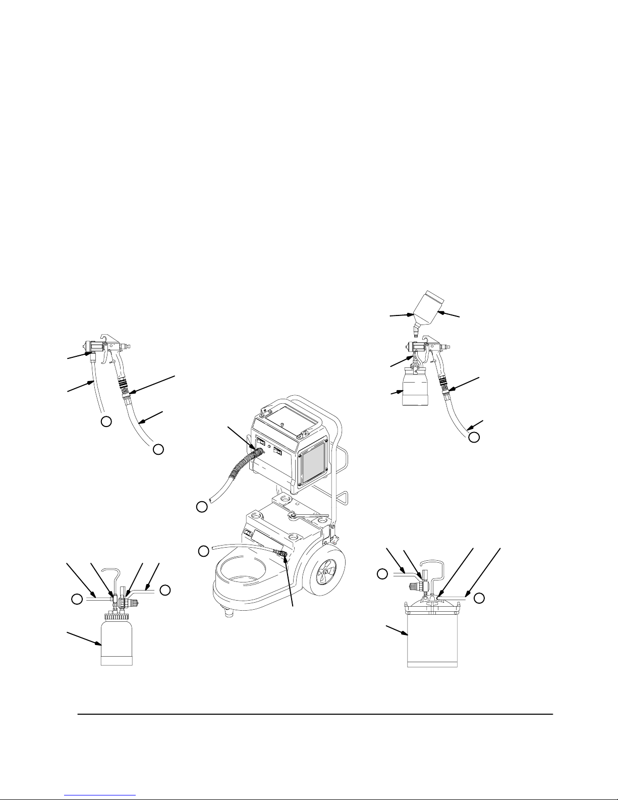
The HVLP Cart/Compressor provides the air supply
for remote pressure pot.
The circled letters in Fig. 1 indicate hose line
connections.
1. Connect gun air supply hose (A) between turbine
air outlet (B) and gun air inlet (C). DO NOT use
wrench to tighten connections; hand tighten only.
See Fig. 1.
For GTS–4900:
The turbine uses quick connector at outlet (B). A
wrench is not required for hose connection.
2. If using a spray gun cup (D):
Connect cup to gun fluid inlet (E).
If using accessory remote pressure pots (F):
Connect fluid supply hose (G) between remote
pressure pot fluid outlet (H) and gun fluid inlet (E).
3. Connect pressure pot air hose (J) between pressure pot air regulator inlet (K) and the cart compressor air outlet.
Install Fluid Set
Complete spray guns are available with #1, #2, #3, #4,
or #5 fluid sets. To install other fluid sets, perform the
following steps. See Fig. 2.
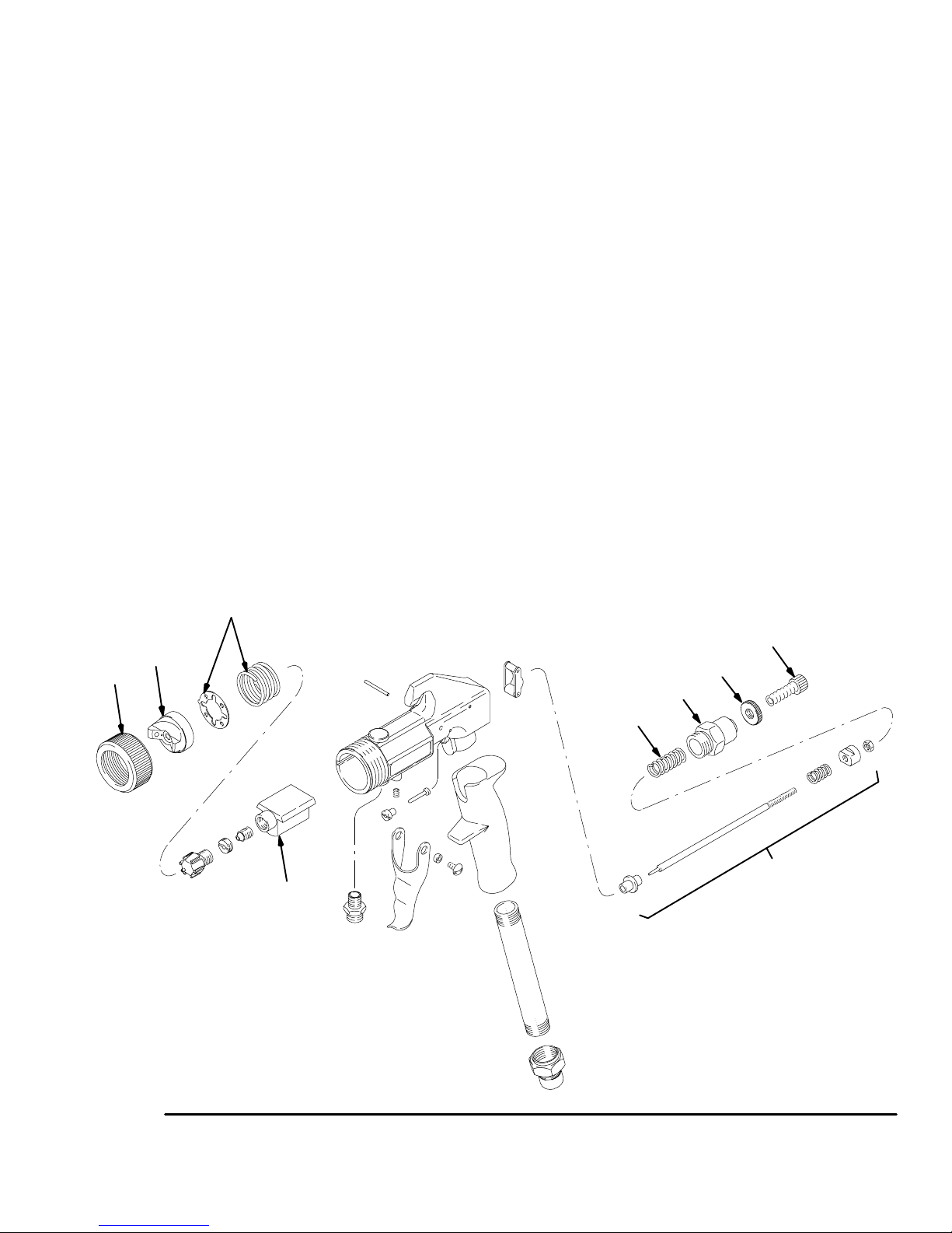
1. Remove air cap retaining ring (29). Discard packaging (not shown). Remove detente plate and
spring (25).
2. Remove fluid regulator assembly (20, 21, 22) and
spring (23) from back of gun.
D
cup-over option
E
G
Y
remote pressure pot
setup for spray gun
G
H
Y
F
C
A
B
X
X
J
K
Z
Z
L
E
D
X
cup setup for spray gun
J
K
Z
F
H
Y
C
A
G
Fig. 1
4 308336
21/2-gallon remote pressure pot2-quart remote pressure pot
04958B
Page 5
Setup
3. Fully insert needle assembly (14) into back of fluid
manifold (6).
4. Perform needle adjustment procedure steps 2 thru
5 of Adjusting Needle on page 16.
5. Perform needle packings adjustment procedure
steps 4 thru 8 of Adjusting Needle Packings on
page 16.
Prepare 960 Cup Gun for Pressure Feed
1. Remove air pressure tube (34) from air stem (33).
See parts drawing on page 20.
2. Hold fluid inlet fitting (7) with wrench and remove
cup assembly (59).
3. Remove air stem (33) from gun body (1).
4. Apply medium strength threadlocker to set screw
(61) and assemble to gun body.
Prepare Fluid
1. Always strain fluid before spraying; this includes
color, reducer, and hardeners.
2. Use slower drying reducer or thinner to compensate for faster drying time from warm turbine air.
Do not over reduce.
Paint Reduction — Automotive Type Finishes
Reduce and catalyze all paint to manufacturer’s
specifications. Compensate for faster turbine drying
time by using reducer one-step slower than
conventional air spray.
Paint Reduction — Industrial or Domestic
Coatings
Reduce and catalyze all paint to manufacturer’s
specifications. If no reductions are given, first
thoroughly mix fluid to be sprayed. Gradually mix in
reducer, testing fluid for correct spraying consistency.
Test consistency, remove stir stick from thinned paint.
Consistency is right when first drops from stir stick are
about one second apart.
29
27
25
20
21
22
23
14
6
Fig. 2
05289
308336 5
Page 6
Fill Cup or Remote Pressure Pot
Spray Gun Cup
Setup
WARNING
The spray gun cup is pressurized by the gun’s air
supply. To reduce the risk of serious injury from
pressurized fluid or accidental spray from the gun,
always turn off the air supply to the gun before
removing the spray gun cup.
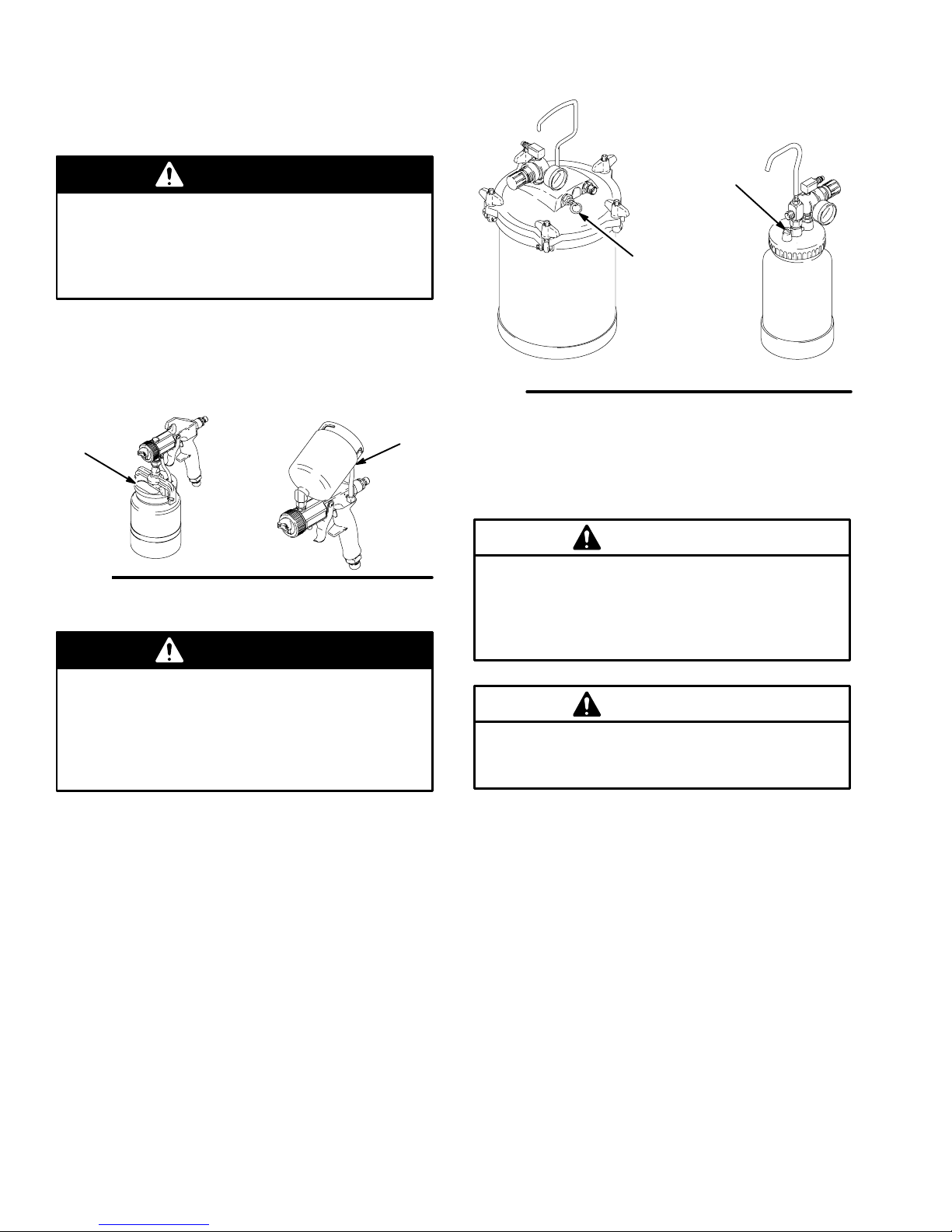
Fill cup 3/4 full to keep air pressure tube clean. Install
cover. Under-cup cover has latch (H) to secure it to
cup. Over-cup has ring with notches (J) that secure
cup hood when locked in place on cup.
H
Fig. 3
Accessory Remote Pressure Pot
05292A
J
05292
WARNING
113
206c
1
2
/
gallon
2
02860
Fig. 4
2. Remove pressure pot cover and fill. Secure cover.
NOTE: 2-quart remote pressure pot only:
Lightly coat cover threads with petroleum jelly.
2 quart
02882
CAUTION
If the 2-quart remote pressure pot is accidentally
tipped over or held at too great of an angle, fluid
may leak into the air regulator and cause damage.
Take precautions to avoid this. If fluid does get into
the regulator, clean immediately.
The accessory remote pressure pots remain
pressurized until pressure is manually relieved. To
reduce the risk of serious injury from pressurized
fluid or accidental spray from the gun, always
relieve pressure in the pressure pot before
loosening or removing the cover.
1. Relieve remote pot pressure as follows:
a. Turn off air supply to pressure pot. See Fig. 4.
b. 21/2-gallon remote pressure pot:
Pull pressure relief valve ring (206c) until
pressure is completely relieved.
2-quart remote pressure pot:
Turn out pressure relief knob (113) one turn.
Wait until pressure is completely relieved
before removing cover. Close knob.
CAUTION
Do not tighten the pressure pot cover more than
hand-tight. Excessive tightening may damage the
cover gasket.
6 308336
Page 7
Setup
Prepare Surface
To achieve proper adhesion, make sure the surface to
be sprayed is completely clean.
Turbine Operation
WARNING
Sparking can be expected in the normal operation
of the turbine motor. Sparks can ignite fumes from
flammable liquid, dust particles, and other
flammable substances in the spray area. This can
cause serious injury and property damage. Be sure
to follow the precautions below:
When flammable liquid is sprayed or used for
flushing or cleaning equipment, the turbine must
be placed at least 20 feet (6.1 m) away from
areas where hazardous concentrations of
flammable vapors are likely to occur.
Use additional air hose if necessary to ensure
that the turbine is operated in a clean, dry,
well-ventilated area.
Cold Weather Operation
The HVLP compressor/cart uses a diaphragm
compressor. When new, the diaphragm may becomes
stiff in cold weather. If cold enough, the diaphragm will
not allow the compressor motor to start (the unit will
hum). If this occurs, follow these steps:
1. Turn turbine and compressor OFF.
2. Unplug turbine from power source.
3. Pinch and remove filter by hand. Clean or replace
if dirty.
4. Hand spin cooling fan on compressor for a few
revolutions.
5. Reinstall filter.
6. Plug in turbine.
7. Turn turbine and compressor ON. If necessary,
repeat procedure.
Adjust Pattern Direction and Shape
Never use or place the turbine inside a spray
booth! Use this equipment outdoors or in
extremely well-ventilated areas.
Avoid all ignition sources such as static
electricity from plastic drop cloths, open flames
such as pilot lights, hot objects such as
cigarettes, arcs from connecting or
disconnecting power cords, and arcs from
turning light switches on and off. Extinguish or
remove all sources of ignition.
1. Turn turbine on a few minutes before spraying to
warm-up.
NOTE: Turn turbine off when not in use. Turbine
does not shut off automatically.
2. Be sure the turbine filter is clean before operating.
See Turbine Filter Maintenance on page 13.
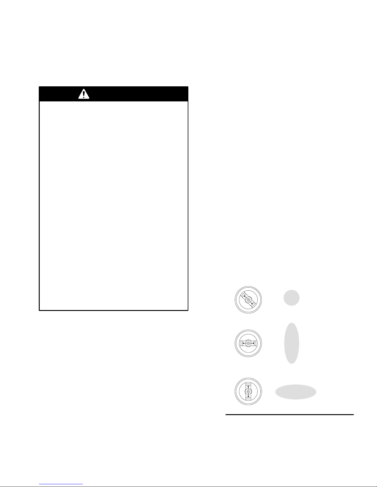
Spray pattern direction and shape are determined by
3 different positions the air cap. See Fig. 5. Rotate air
cap as needed to achieve desired pattern.
NOTE: Do not loosen air cap retaining ring to change
patterns unless air cap is set to its widest pattern. See
Fig. 10 on page 9.
Round Pattern
Vertical Pattern
Horizontal Pattern
Fig. 5
02847
308336 7
Page 8
Setup
Adjust Spray Pattern
Select fluid set for fluid to be sprayed. If needed, see
pages 10 and 11 to determine correct fluid set.
WARNING
Do not exceed the gun’s 50 psi (0.35 MPa,
3.5 bar) Maximum Inlet Fluid Pressure and
100 psi (0.7 MPa, 7 bar) Maximum Inlet Air
Pressure. Higher pressures can cause parts to
rupture and result in serious injury or property
damage.
To establish correct fluid flow:
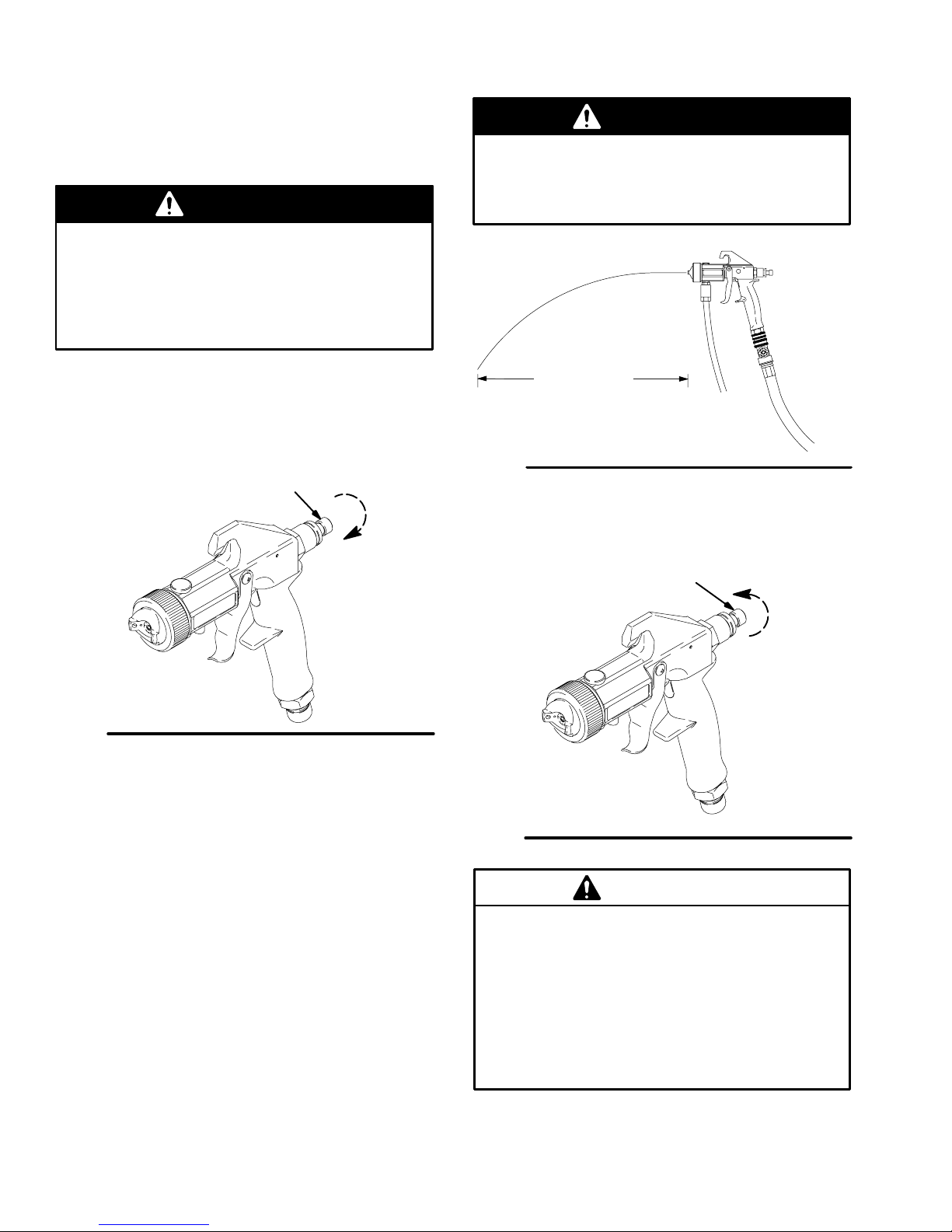
1. Turn fluid adjustment knob (20) counterclockwise
until you cannot feel any restriction of trigger
movement. See Fig. 6.
20
open
WARNING
Over-pressurizing the accessory remote
pressure pots can cause serious injury. To
reduce the risk, never exceed 50 psi (0.35 MPa,
3.5 bar) Maximum Inlet Fluid Pressure.
8 to 10 in.
(203 to 254 mm)
Fig. 7
3. If further gun fluid adjustment is needed, turn fluid
adjustment knob (20) clockwise to reduce volume
of fluid output. See Fig. 8.
05284
Fig. 6
2. For remote pressure pot, hold gun parallel to floor
and adjust fluid pressure at 8 to 10 inch (203 to
254 mm) fluid stream. See Fig. 7.
For 2-quart remote pressure pot:
Set at 4 to 6 psi (0.28 to 0.42 bar).
For 21/2-gallon remote pressure pot:
Set at 8 to 10 psi (0.56 to 0.70 bar).
Note: Heavier fluids or longer fluid hoses require
greater pressures.
05292
20
close
05292
Fig. 8
CAUTION
Restricting the trigger and fluid needle travel by
continuously spraying with the fluid adjustment
knob closed (turned clockwise), will cause
accelerated abrasive wear on the fluid needle and
wear on the trigger.
8 308336
For best results, adjust fluid flow at the pressure
source or use a different size needle/nozzle/air cap
combination.
Page 9
Setup
To establish correct air flow:
4. Test spray pattern and atomization while holding
gun about 6 to 8 inches (150 to 200 mm) from test
piece.
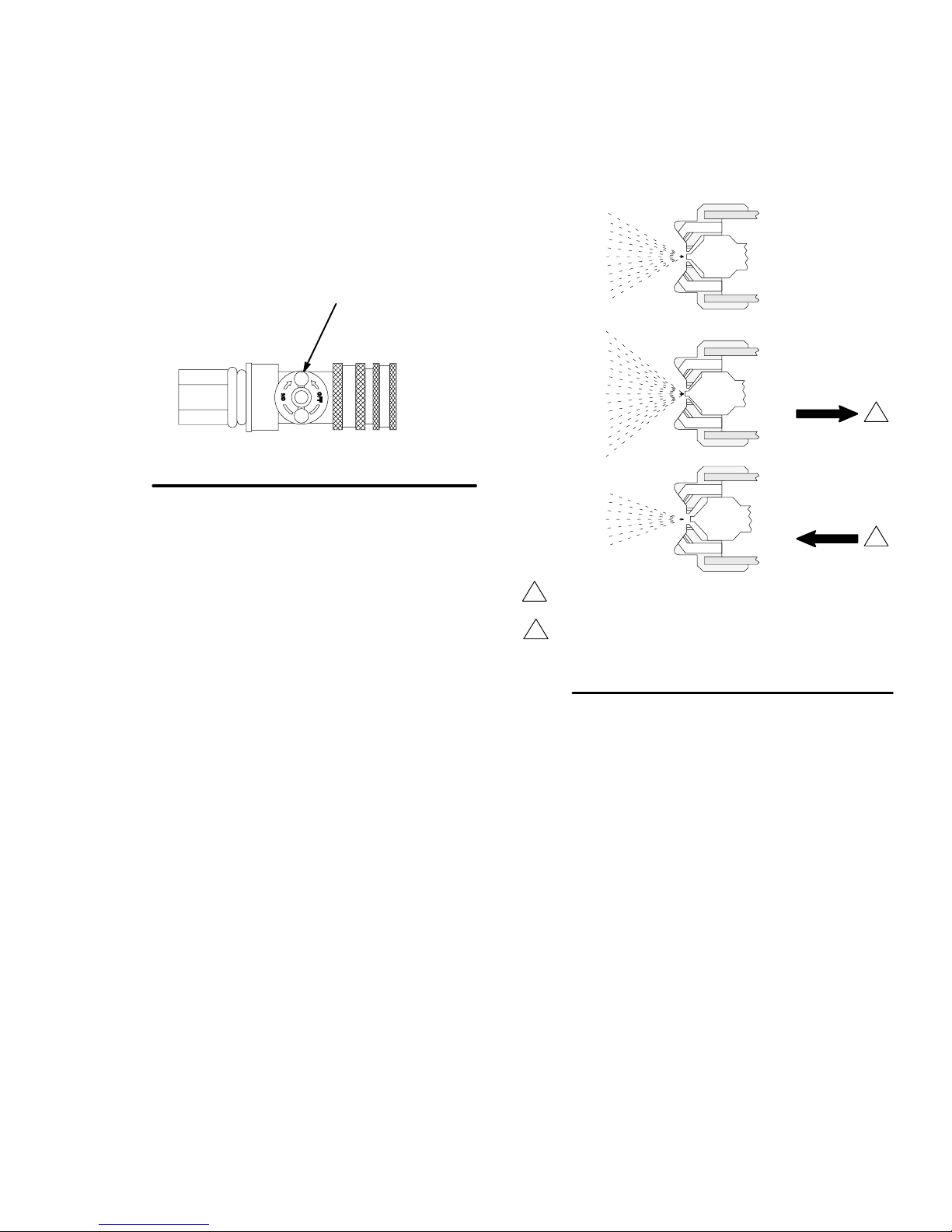
5. Air Control Valve (M) on end of turbine hose
controls both atomizing air and pressure in spray
gun cup. See Fig. 9. Adjust air control valve as
needed.
M
Fig. 9
02850
NOTES:
Control over-spray mist by using only as much air
as necessary to spray fluid. Lighter fluids require
less air.
If atomization is still unacceptable, fluids may be
thinned further or a different fluid set may be
required. See pages 10 and 11 to determine fluid
set or page 5 to prepare fluid.
Adjust Pattern Size
Change pattern size by turning air cap retaining ring in
for a wide pattern or out for a narrow pattern. See
Fig. 10.
Normal
Spray
Pattern
Wider
Spray
Pattern
Narrower
Spray
Pattern
1
Turning air cap in too far will retard atomization.
2
Turning air cap out too far, will stop fluid or
cause flutter.
Fig. 10
Air Cap Flush
with Fluid
Nozzle
Turn Air Cap
Retaining
Ring In
1
Turn Air Cap
Retaining
Ring Out
2
02851
308336 9
Page 10

Setup
Contractor Fluid Set Chart
Use this chart to determine Fluid Set for specific contractor application. See Fig. 11.
Fluid Set Components
Fluid Set
P/N & Size
240112
#2 (0.8 mm)
240113*
#3 (1.3 mm)
240114
#4 (1.8 mm)
240115
#5 (2.2 mm)
240116
#6 (2.5 mm)
* Standard fluid set
** Fluid measured with a #4 Ford cup (Part No. M70702)
(A)
Air Cap
240490 192911 192916 light
240491 192912 192917 light – medium
240492 192913 192918 medium
240493 192914 192919 heavy
240494 192915 192920 heavy
(B) Nozzle (C)
Needle
Type of
Fluid**
14 to 18 sec.
18 to 22 sec.
20 to 26 sec.
22 to 26 sec.
26+ sec.
Fine finish work with stains, lacquers, waterborne lacquers
Medium speed application with lacquers,
enamels, urethanes, and varnish
Medium to high speed industrial finishes
Heavy output with lacquer and enamels, latex
and oil wall paints
Wax base stripper, sound deadeners, latex
paint, multi-color
Automotive Fluid Set Chart
Use this chart to determine Fluid Set for specific automotive application. See Fig. 11.
Fluid Usage
Fluid Set
P/N & Size
240117
0.5/0.5M mm
240118
0.7/0.7M mm
240113*
#3 (1.3 mm)
240119
#1 (1.0 mm)
* Standard fluid set
Multi-hole air cap
Fluid Set Components
(A)
Air Cap
M70434
0.5 mm
M70437
0.7 mm
240491 192912 192917 Normal output with enamels, urethanes, zinc
M70439 M70448 M70457 Medium-speed application with all automotive
(B)
Nozzle
M70446 M70453 Ultra fine finish with automotive touch-up,
M70447 M70455 Fine finish work with all automotive finishes, color
(C)
Needle
Fluid Usage
spot jobs
matching, automotive base coat
chromate, automotive primers
finishes
10 308336
Page 11
Setup
Using Fluid Set Charts
Turbine Spray Gun includes a #3 fluid set, Part No.
240113. The size of air cap, fluid nozzle, and fluid
needle are marked on parts.
Use fluid set charts on page 10 to order different size
fluid set or to find part number of individual
components of fluid set. Charts identify fluid sets used
in contractor and automotive applications.
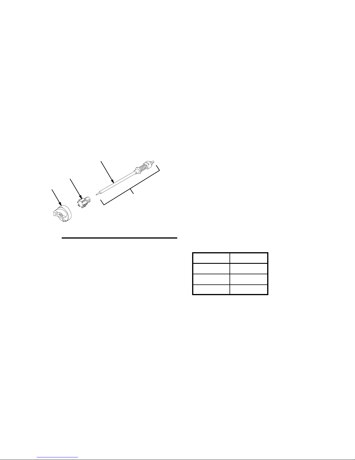
Fluid sets include air cap (A), nozzle (B), and needle
assembly (D). See Fig. 11.
NOTE: To order other replacement parts for gun, see
parts drawings and parts lists for gun model on pages
20 to 23.
C
B
A
D
Selecting Fluid Set
Turbine spray gun fluid sets range in size to provide
different fluid flow rates. Selection charts on page 10
show recommended combinations based on fluid
viscosities, flow rates, and usage.
As a general guideline, use fluid nozzle that will give
required flow with needle fully triggered at lowest fluid
pressure.
For low flow rates or light viscosity fluid, select smaller
nozzle sizes.
For high flow rates or high viscosity fluid, select larger
nozzle sizes.
To eliminate mist, use air cap one size larger than fluid
nozzle. Use of smaller size air cap produces finer
finish, but can increase mist.
For very fine finish work (automotive, furniture, etc.),
order air cap two sizes smaller than needle and nozzle.
0.5M mm or 0.7M mm multi-hole air caps are
recommended for automotive finishes. See
Automotive Fluid Set Chart on page 10.
Fig. 11
Fluid Set
02981
For narrow fan pattern (wood finishing), order
0.5W mm, 0.7W mm, or 1.0W mm narrow fan pattern
air cap. See chart below for part numbers.
Narrow Fan Pattern Air Caps
Air Cap P/N Size
M70435 0.5W mm
M70438 0.7W mm
M70441 1.0W mm
308336 11
Page 12
Shutdown
Pressure Relief Procedure
WARNING
PRESSURIZED EQUIPMENT HAZARD
The equipment stays pressurized until pressure is
manually relieved. To reduce the risk of a serious
injury from pressurized fluid, accidental spray from
the gun, or splashing fluid, follow the Pressure Re-
lief Procedure whenever you:
are instructed to relieve the pressure,
stop spraying,
check or service any of the system equipment,
or install or clean the fluid nozzles.
1. When spraying is finished, turn off air supply to
gun.
2. Turn off turbine sprayer.
WARNING
The turbine hose outlet may be hot. Carefully
check the hose end before removing the hose.
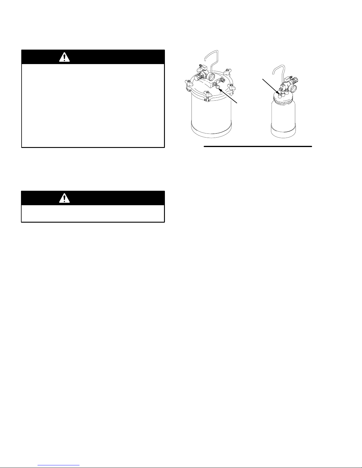
3. If using remote pressure pot:
Relieve pressure by following these steps:
113
206c
1
2
/
gallon
2
02860
Fig. 12
NOTE: Elevate spray gun and pull trigger. This will
allow fluid in fluid hose to drain back into remote
pressure pot.
4. If using a spray gun cup:
Unlatch cup cover and loosen or remove cup from
cover to relieve cup pressure.
5. Clean spray gun and cup as instructed on
page 14.
2 quart
02882
a. Turn off air supply to pressure pot.
b. 21/2-gallon remote pressure pot:
Pull pressure relief valve ring (206c) until
pressure is completely relieved.
2-quart remote pressure pot:
Turn out pressure relief knob (113) about one
turn. Wait until pressure is completely relieved
before removing cover. Close knob. See
Fig. 12.
12 308336
Page 13
Spraying Techniques
General Spraying Techniques
Select proper fluid set. To determine correct fluid
set see charts on page 10.
When fluid is first applied, start with fluid nozzle and
air cap adjusted to “normal spray pattern” position.
Then adjust as needed. See Fig. 10 for pattern size
adjustment.
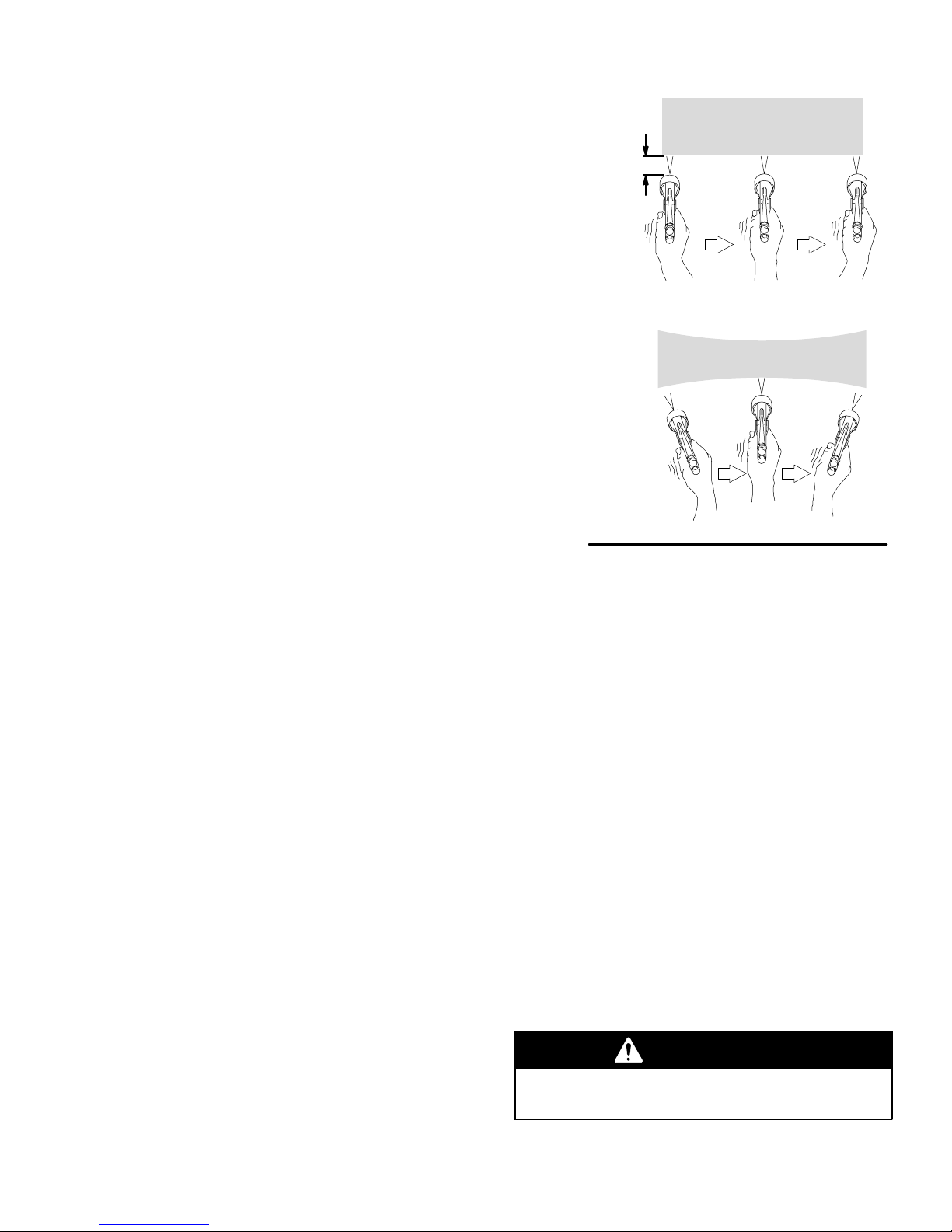
Keep gun perpendicular to surface and maintain
consistent distance of approximately 6 to 8 inches
(150 to 200 mm) from object being sprayed. See
Fig. 13.
Always have spray gun in motion before triggering.
Move spray gun across workpiece in straight,
smooth, stroke. Maintaining speed and distance.
Release trigger at end of stroke.
To obtain even finish, overlap previous strokes
by 50%.
Apply full, wet coat whenever possible.
6 to 8 in.
(150 to 200 mm)
0793
RIGHT
Automotive Spraying Techniques
When blending spots, work from outside in.
Two lengths of 20 foot (6.1 m) hose are
recommended when applying automotive finish
coats. Additional hose allows air to cool for better
flow.
Maintenance
Turbine Filter Maintenance
Turbine systems are lifetime lubricated. The only
maintenance required is filter cleaning and
replacement.
Turbine main filter and pre-filter must be clean at all
times to provide sufficient air flow to cool motor and
atomize fluid. Check pre-filter cleanliness daily. Check
main paper filter weekly. Clean as necessary.
NOTE: To check filter, turn on turbine and place piece
of paper against pre-filter. If air intake holds paper in
place, filter is okay.
Fig. 13
To clean main filter:
1. Turn off and unplug turbine.
2. Loosen four main filter screws, remove filter retainer and pre-filter.
3. Remove main filter and clean by one of the following methods:
Tap filter gently on flat surface, dirty side
down.
Direct maximum of 100 psi (0.7 MPa, 7 bar)
compressed air through filter panel in opposite
direction of arrows on side of filter.
Soak filter 15 minutes in water and mild deter-
gent. Rinse filter until clean. Air dry filter; do
not use compressed air.
WRONG
0793
WARNING
To avoid damage to turbine and possible electric
shock, never install damp filter in turbine.
308336 13
Page 14
Maintenance
Flushing Spray Gun Using Remote
Pressure Pot
WARNING
The spray gun cups and accessory remote
pressure pots remain pressurized until pressure is
manually relieved. To reduce the risk of serious
injury from pressurized fluid or accidental spray
from the gun, always relieve pressure in the cup or
pressure pot before checking or servicing any part
of the spray system; before installing, cleaning or
changing fluid nozzles; before loosening or
removing the accessory remote pressure pot
cover; and whenever you stop spraying.
NOTES:
Check for any fluid leakage from gun and fluid
hoses. Tighten fittings or replace equipment as
needed.
Flush gun before changing colors and whenever
you are done spraying.
CAUTION
5. Relieve pot pressure, as described in Step 2.
6. Disconnect air and fluid hoses from gun.
7. Clean and lubricate gun as instructed starting on
page 15.
Flushing Spray Gun and Cup
1. Turn off air supply to gun.
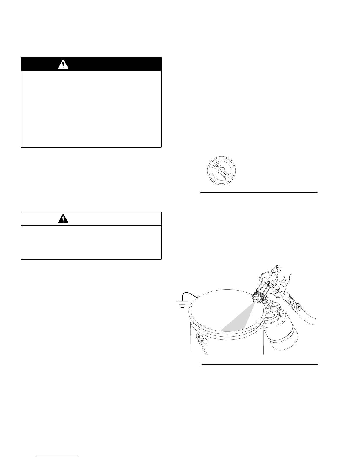
2. Unlatch cup cover and remove cup from cover.
3. Turn air cap to round pattern position. Turn air
control valve half open to reduce solvent mist. See
Fig. 14.
Air Cap Round
Pattern Position
Fig. 14
4. Fill empty cup with about 1 1/2 inches (38.1 mm) of
compatible solvent and reinstall cup. Be sure cover
is secured.
02847
Clean all parts with a solvent compatible with the
fluid being sprayed and compatible with the spray
gun and cup or accessory remote pressure pot
wetted parts. See Technical Data on page 25.
1. Turn off air supply to gun.
2. Relieve pot pressure as follows:
a. Turn off air supply to pressure pot.
b. 21/2-gallon remote pressure pot:
Pull pressure relief valve ring (206c) until
pressure is completely relieved.
2-quart remote pressure pot:
Turn out pressure relief knob (113) about one
turn. Wait until pressure is completely relieved
before removing cover. Close knob. See
Fig. 12.
3. Fill pressure pot with compatible solvent.
4. Flush spray gun, using compressor air only. Point
gun down into container and flush until solvent
runs clean.
5. Turn on air to gun.
6. Point gun down into container and flush until
solvent runs clean. See Fig. 15.
Fig. 15
7. Turn off air to gun.
8. Disconnect air supply and remove cup from gun.
Clean and lubricate gun as instructed on pages 15
and 16.
05290AA
14 308336
Page 15
Maintenance
Clean Spray Gun
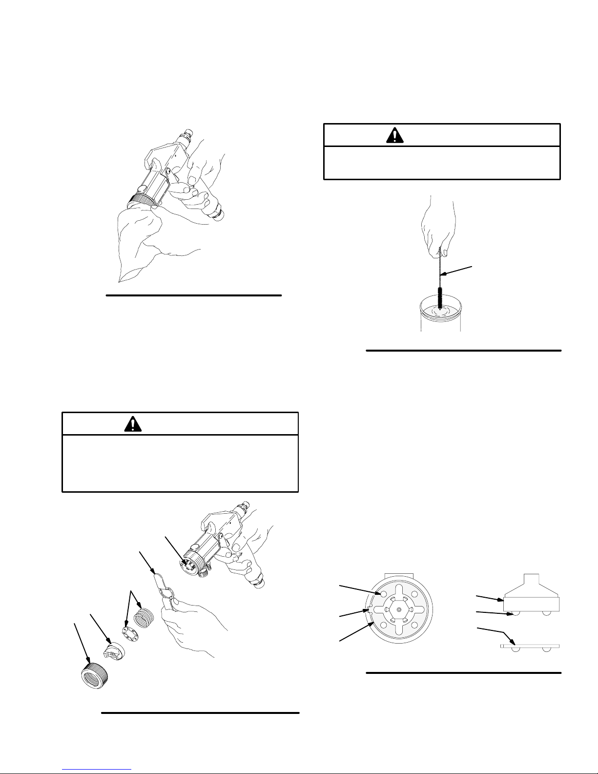
1. Clean gun and cup by hand with compatible solvent or place them in gun washer with trigger held
open; cycle washer as necessary to clean gun.
05293
Fig. 16
2. Remove air cap retaining ring (29), air cap (27),
spring and detent plate (25). See Fig. 17.
3. Trigger gun while removing fluid nozzle (19) with
nozzle wrench (P), provided. See Fig. 17.
4. Remove gun fitting (22) from back of gun. Remove
needle for cleaning.
5. Soak air cap, detent plate and fluid nozzle in
solvent. At a minimum, clean air cap and fluid
nozzle daily. Use solvent and brush (R), provided.
See Fig. 18. Some applications require more
frequent cleaning. Keep all air cap holes clean.
CAUTION
Clean air cap horn holes with a non-metallic item to
avoid permanently damaging them.
R
Fig. 18
6. With gun pointed down, clean front of gun, using
brush and solvent.
7. Trigger gun while installing fluid nozzle (19) with
nozzle wrench (P). See Fig. 17.
02856
CAUTION
Trigger the gun whenever you tighten or remove
the nozzle. This keeps the needle seat away from
the nozzle seating surface and prevents the seat
from being scratched.
19
P
25
27
29
Fig. 17
05291
8. Install spring (25) into front of gun.
9. Install detent plate (25) into gun housing with open
sockets (S) facing up; align detent plate tab (T)
with notch in gun housing. See Fig. 19.
10. Install air cap (27), aligning air cap balls (U) with
detent plate sockets (S). See Fig. 19. Secure air
cap with air cap retaining ring (29).
NOTE: If installed correctly, air cap will snap into four
definite positions, with no loose rotation.
S
T
25
Fig. 19
11. Lubricate gun after cleaning it as instructed on
page 16.
27
U
S
02966
308336 15
Page 16
Service
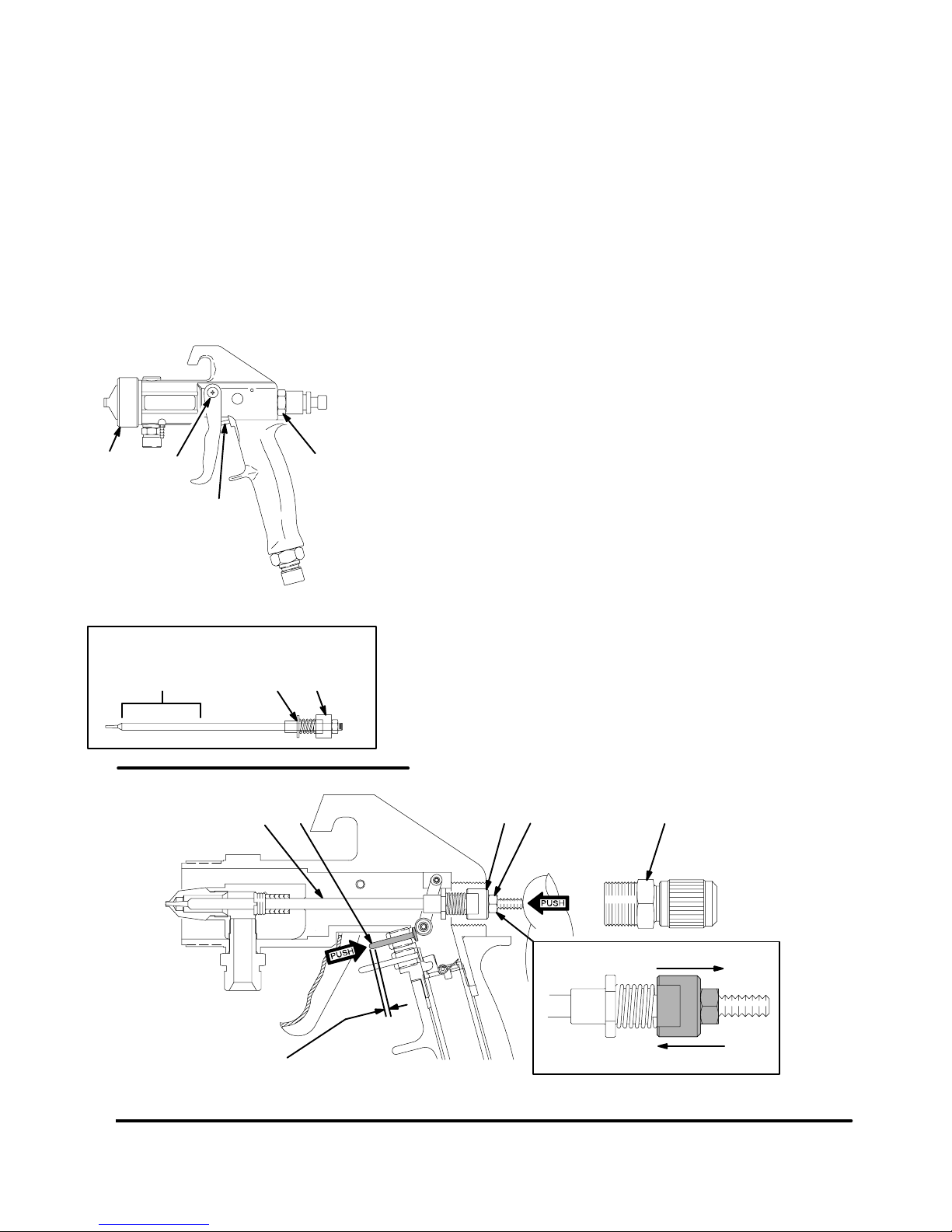
Lubricate Spray Gun
After cleaning or servicing gun, lubricate parts
indicated in Fig. 20 with silicone-free spray gun
lubricant or similar material.
All threaded areas (A)
Trigger screws (B)
Trigger axle (C)
Fluid needle assembly (D) — where indicated
A
B
C
A
05288
Replace and Adjust Needle
The needle may need to be adjusted whenever you
change nozzle/needle sizes or to compensate for
wear.
To replace needle:
1. Fig. 21. Remove fitting (22) and spring (23-not
shown) from back of gun.
2. Remove needle (14).
3. Insert new needle (14).
To adjust needle:
4. Hold needle (14) with thumb and push upper
trigger pin (A) with index finger. Fig. 21. Trigger pin
must travel approximately 1/16 in. (2 mm) under
light spring pressure.
5. If there is not 1/16 in. of travel, loosen adjustment
nut (18) and turn drum (17) until trigger pin (A) has
about 1/16 in. (2 mm) free travel before needle
(14) starts to move.
6. Lock adjustment nut (18).
Fluid Needle Assembly
2 in. (50.8 mm)
Fig. 20
1/16 in. (2 mm)
Fig. 21
free travel
7. Make sure spring (23) is in place in fitting (22),
then install fitting. Hand-tighten fitting.
D
DD
02949, 02950
18
1714
8077A
Model 980 shown
22A
More Travel
Less Travel
8669A
16 308336
Page 17
CAUTION
Trigger the gun whenever you tighten or remove
the nozzle. This keeps the needle seat away from
the nozzle seating surface and prevents the seat
from being scratched.
19
P
25
27
29
Service
DETAIL
9 8K
Fig. 22
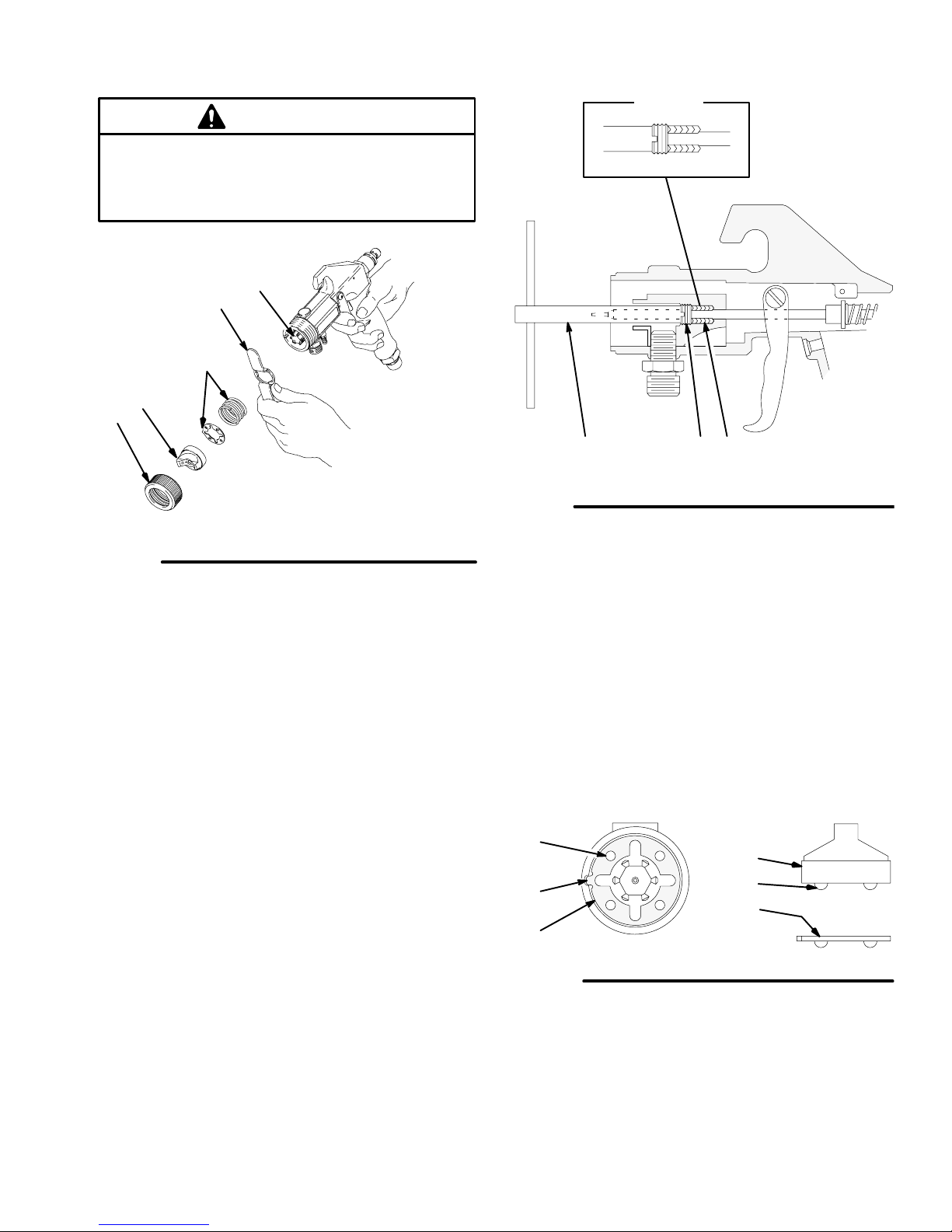
8. Trigger gun while slightly turning packing nut (9)
clockwise with packing wrench (K), provided. See
Fig. 23. This will compress packings.
The packings need very little pressure to seal well.
If needle binds, packings are too tight; back packing nut off 1/16 turn. Needle should then move
freely. If packings are over-tightened, they may be
damaged and need to be removed and replaced.
05291
Fig. 23
9. Trigger gun while installing fluid nozzle (19) with
nozzle wrench (P). See Fig. 22.
10. Install spring (25) into front of gun.
11. Install detent plate (25) into gun housing with open
sockets (S) facing up; align detent plate tab (T)
with notch in gun housing. See Fig. 24.
12. Install air cap (27), aligning air cap balls (U) with
detent plate sockets (S). See Fig. 24. Secure air
cap with air cap retaining ring (29).
NOTE: If installed correctly, air cap will snap into 4
definite positions, with no loose rotation.
S
T
25
27
U
S
02858
Fig. 24
02966
308336 17
Page 18

Troubleshooting
Spray Finish Problems
PROBLEM CAUSE SOLUTION
Orange peel finish — Paint
surface not smooth
Blushing — Clear coatings
appear milky
Paint droplets too large. Maintain proper spraying distance;
see page 13.
Keep the turbine air filters clean to
allow full air flow. See page 13.
Do not use an air hose that is too
long to provide sufficient atomization pressure.
If droplets are still too large, reduce
the fluid or use a smaller air cap.
Paint droplets drying too fast to
properly flow out of gun.
Cold weather spraying. Keep the fluid and the object being
Moisture condensation is trapped in
the lacquer when spraying in hot,
humid conditions.
Keep the object being sprayed out of
direct sunlight. When spraying in
warmer temperatures, use a slower
evaporating solvent or a retarder.
sprayed as close to room temperature
as possible. When sprayed on a cold
surface, most paints will become too
thick to flow properly.
See Cold Weather Operation on
page 7.
Allow the turbine to warm up a few
minutes before spraying.
Store the lacquer off concrete
floors, at room temperature.
Apply lighter coats and allow for
proper drying time.
Use a slower evaporating solvent
or retarder.
Do not spray in windy conditions.
Fish eyes — Small pools on
painted surface that will not
fill
Runs and sags Applying too much paint per pass for
Solvent pops or bubbles Sprayed surface drying before solvent
18 308336
Silicone contamination from lubricants,
grease, polish, or waxes on the
surface being sprayed.
the drying conditions.
gas can be released.
Clean all parts with a cleaning solvent;
use a solvent rag and a clean rag to
wipe with. Replace rags as needed. If
the problem persists, use a fish eye
eliminator.
Move the gun faster or decrease
the fluid flow.
Maintain proper spraying distance;
see page 13.
Reduce the amount of thinner or
use a faster drying thinner.
Apply fluid in lighter coats to allow
for proper evaporation.
Use the recommended thinners.
Follow the solutions, above, for
Orange peel finish — paint droplets
too large.
Page 19

Troubleshooting
Spray Gun Problems
PROBLEM CAUSE SOLUTION
No or slow fluid flow, intermittent spray, or fluttering
spray
Proper size fluid set is not being used. Select the proper fluid set for the fluid
being sprayed. See page 10.
Air cap is adjusted too far forward. Adjust the air cap to “normal” position.
See page 9.
Gun fluid nozzle is not tight enough, is
blocked by dried paint, or is damaged.
Cup or pressure pot cover is not tight
enough or gasket is damaged.
Cup or pressure pot fluid tube blocked
by dried paint or is damaged.
Air flow to cup is blocked. To check: remove the cup (leave cover
Needle packings are not properly adjusted. Fluid loss though the packings
will effect fluid pressure and cause a
fluid build-up in the gun body.
Needle is not properly adjusted. Fluid
flow will be restricted if there is too
much free travel between the trigger
and needle.
Tighten, clean or replace fluid nozzle.
Tighten cover or replace gasket.
Clean or replace fluid tube.
connected), trigger the gun and check
for air flow out of the cup lower pressure tube. If air is not flowing freely,
clean the air passage tubes.
Clean the gun body with solvent and
the brush provided. Adjust the needle
packings as instructed on page 17.
Adjust the needle as instructed on
page 16.
Fluid leaks at fluid nozzle
after the trigger is released
Poor spray pattern Air cap horn holes and/or fluid nozzle
Needle is not seating in the fluid
nozzle.
plugged.
Check for a loose fluid nozzle or a
bent nozzle or needle; tighten the
nozzle or replace parts as needed.
Check the needle adjustment; see
page 16.
Check the needle packings adjust-
ment; see page 17.
Soak air cap and/or fluid nozzle in solvent. Clean air cap horn holes with
non-metallic item to avoid permanently
damaging them. See page 15.
308336 19
Page 20
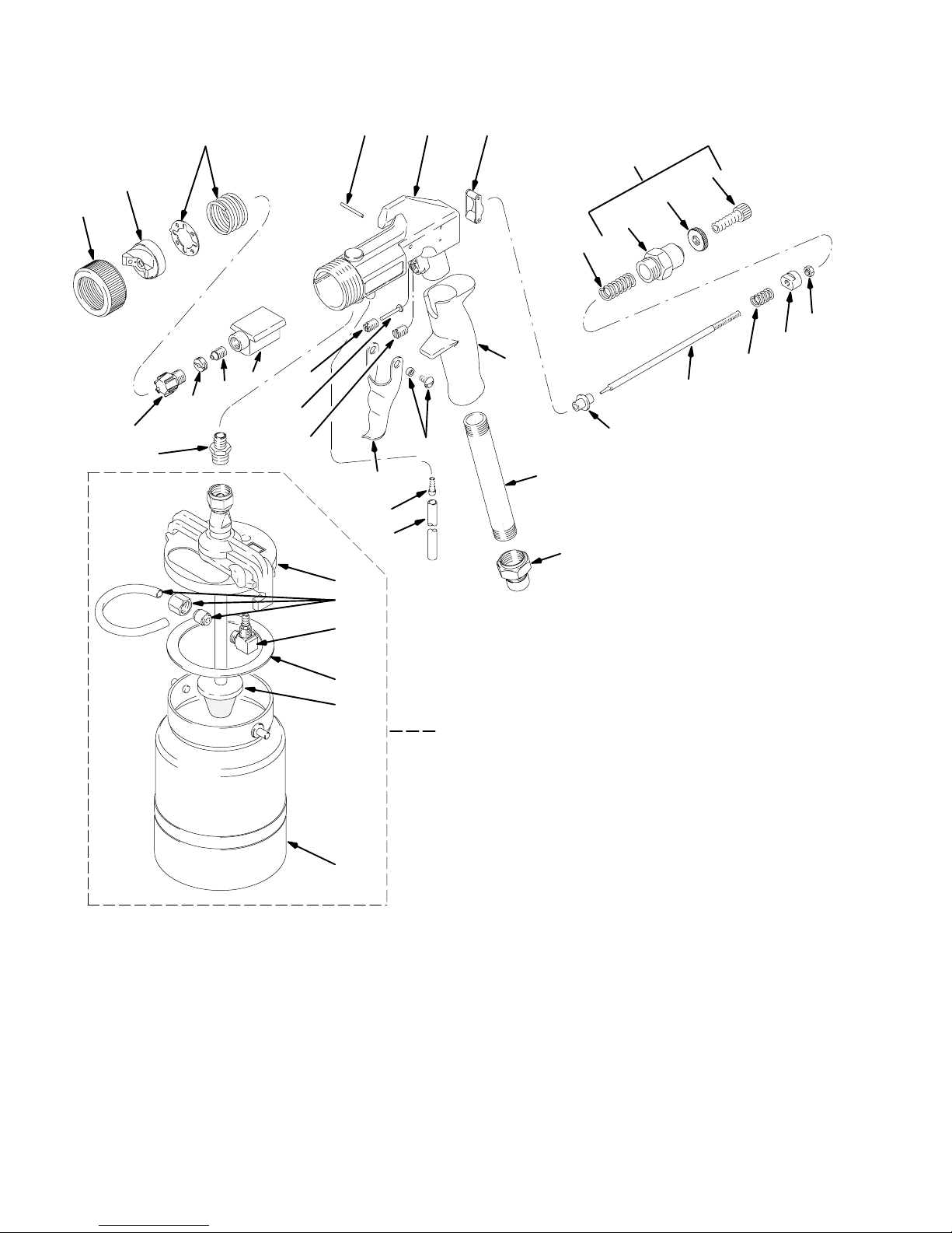
Parts for Model 960
29
27
19
*25
*5
6
*8
*9
7
*4
62
3* 1 2*
11*
10
33
*34
39
51
56
57
23
58
60
22
15
NOTE: The air cap (27), fluid
nozzle (19), and fluid needle
parts (14 to 18) are available as
complete fluid sets. See page
10 for part numbers.
20
21
17
16
14
18
40
43
52
44
59
TI0095
20 308336
Page 21

Parts for Model 960
240080 Model 960, without fluid set
240083 Model 960, with #3 fluid set
240084 Model 960, with #4 fluid set
240085 Model 960, with #5 fluid set
243920 Model 960, with 2.0 fluid set
Ref
No. Part No. Description Qty
1 193103 GUN BODY 1
2* M73004 ACTUATOR, needle 1
3* M70388 PIN, actuator 1
4* 193123 PIN, trigger 1
5* 193100 GUIDE, pin 1
6 M70384 MANIFOLD, fluid 1
7 M70401 FITTING, fluid inlet 1
8* M70381 PACKING KIT, fluid; PTFE 1
9* M70380 SCREW, adjustment 1
10 193098 TRIGGER 1
11* M70386 SCREW/BUSHING ASSY., trigger 2
14 – FLUID NEEDLE (See chart on 1
page 10 for part number)
15 M70403 RING, driving 1
16 M70404 SPRING, driving ring 1
17 M70405 DRUM, needle adjustment 1
18 M70406 NUT 1
19 – FLUID NOZZLE (See chart on 1
page 10 for part number)
20 M70467 SCREW, fluid regulating 1
21 M70466 RING, locking 1
22 M70465 FITTING, gun 1
23 M70407 SPRING, needle return 1
Ref
No. Part No. Description Qty
25* 240280 DETENT PLATE/SPRING KIT, air
cap 1
27 – AIR CAP (See chart on page 10
for part number) 1
29 240279 RING, pattern control 1
33 M70394 STEM, air 1
34* 240263 HOSE, air pressure 1
39 240510 LID ASSY 1
40 M71677 ELBOW, with stem 1
43 240265 GASKET, cup; (5 pack) 1
44 240262 CUP; 1 quart (1 liter) 1
51 M71680 KIT, air pressure 1
52 240267 STRAINER, material (3-pack) 1
55 M70612 TOOL KIT; (not shown) Includes a 1
brush, T-wrench, & nozzle wrench
56 193102 HANDLE, gun 1
57 193099 TUBE, gun, handle 1
58 M73003 COUPLING, disconnect, quick 1
59 240260 KIT, 1-quart cup with cover 1
60 M70409 KIT, fluid regulating 1
61 M71149 SETSCREW, plug (not shown) 1
62 193721 PLUG 1
* These parts are included in Repair Kit M73528,
which may be purchased separately.
308336 21
Page 22
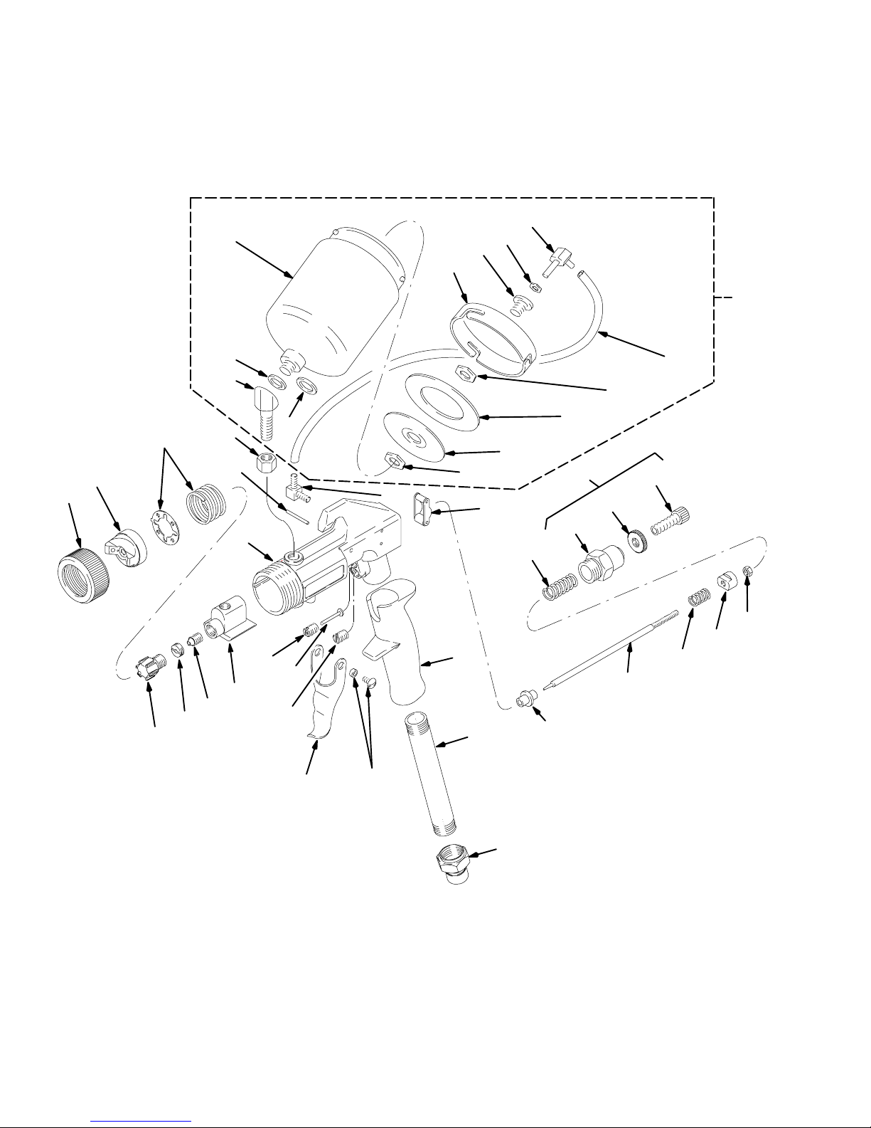
Parts for Models 960GF.5 & 960GF.75
NOTE: Model 960GF.5 includes 1/2-quart (1/2-liter) cup
Model 960GF.75 includes 3/4-quart (3/4-liter) cup
38
47
39
40
41
56
29
27
*25
19
9*
8*
37
34
35
*3
45
44
36
43
44
46
1
*5
*4
6
62
10
11*
2*
23
58
59
60
42
57
21
22
15
NOTE: The air cap (27), fluid
nozzle (19), and fluid needle
parts (14 to 18) are available as
complete fluid sets. See page
10 for part numbers.
20
17
16
14
18
TI0097
22 308336
Page 23

Parts for Models 960GF.5 & 960GF.75
240530 Model 960GF.5, without fluid set
240532 Model 960GF.75, without fluid set
Ref
No. Part No. Description Qty
1 193339 GUN BODY 1
2* M73004 ACTUATOR, needle 1
3* M70388 PIN, actuator 1
4* 193123 PIN, trigger 1
5* 193100 GUIDE, pin 1
6 M70384 MANIFOLD, fluid 1
8* M70381 PACKING KIT, fluid; PTFE 1
9* M70380 SCREW, adjustment 1
10 193098 TRIGGER 1
11* M70386 SCREW/BUSHING ASSY., trigger 2
14 – FLUID NEEDLE (See chart on 1
page 10 for part number)
15 M70403 RING, driving 1
16 M70404 SPRING, driving ring 1
17 M70405 DRUM, needle adjustment 1
18 M70406 NUT 1
19 – FLUID NOZZLE (See chart on 1
page 10 for part number)
20 M70467 SCREW, fluid regulating 1
21 M70466 RING, locking 1
22 M70465 FITTING, gun 1
23 M70407 SPRING, needle return 1
25* 240280 DETENT PLATE/SPRING KIT, air
cap 1
27 – AIR CAP (See chart on page 10 1
for part number)
29 240279 RING, pattern control 1
Ref
No. Part No. Description Qty
34 M71031 FITTING, fluid inlet 1
35 M71030 NUT 1
36 M71033 WASHER, brass 1
37 M71032 GASKET 1
38 M71035 CUP, 1/2 quart (1/2 liter);
Model 960GF2 only 1
M71034 CUP, 3/4 quart (3/4 liter);
Model 960GF3 only 1
39 M71040 NUT 1
40 M71039 BOLT, cup over 1
41 M71037 COVER, cup over 1
42 M71427 GASKET, cup, polyethylene, 1
(5 pack)
43 M71021 HOOD, cup 1
44 M71019 NUT 2
45 M71045 HOSE, air pressure 1
46 M70393 ELBOW CONNECTOR, hose 1
47 M71046 ELBOW CONNECTOR, hose 1
55 M70612 TOOL KIT; (not shown) Includes a 1
brush, T-wrench, & nozzle wrench
56 M71047 KIT, cup over, 1/2 liter 1
57 M70409 KIT, fluid regulating 1
58 193102 HANDLE, gun 1
59 193099 TUBE, gun, handle 1
60 M73003 COUPLING, disconnect, quick 1
62 193721 PLUG 1
* These parts are included in Repair Kit M73528,
which may be purchased separately.
308336 23
Page 24
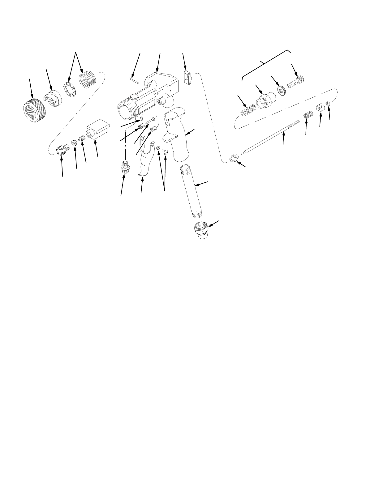
Parts for Model 960P
*25
27
29
9*
19
240772, without fluid set
240773, with #3 fluid set
243592, with #1 fluid set
8*
3* 1 2*
59
21
22
23
61
*5
*4
6
62
10
7
11*
56
57
15
NOTE: The air cap (27), fluid nozzle
(19), and fluid needle assembly (14)
are available as complete fluid sets.
See page 10 for part numbers.
58
20
18
17
16
14
TI0096
Ref
No. Part No. Description Qty
1 193103 GUN BODY 1
2* M73004 ACTUATOR, needle 1
3* M70388 PIN, actuator 1
4* 193123 PIN, trigger 1
5* 193100 GUIDE, pin 1
6 M70384 MANIFOLD, fluid 1
7 M70401 FITTING, fluid inlet 1
8* M70381 PACKING KIT, fluid; PTFE 1
9* M70380 SCREW, adjustment 1
10 193098 TRIGGER 1
11* M70386 SCREW/BUSHING ASSY., trigger 2
14 – NEEDLE ASSY. (See chart on
page 10 for part number) 1
15 M70403 RING, driving 1
16 M70404 SPRING, driving ring 1
17 M70405 DRUM, needle adjustment 1
18 M70406 NUT 1
19 – FLUID NOZZLE (See chart on
page 10 for part number) 1
Ref
No. Part No. Description Qty
20 M70467 SCREW, fluid regulating 1
21 M70466 RING, locking 1
22 M70465 FITTING, gun 1
23 M70407 SPRING, needle return 1
25* 240280 DETENT PLATE/SPRING, air cap 1
27 – AIR CAP (See chart on page 10
for part number) 1
29 240279 RING, pattern control 1
55 M70612 TOOL KIT; (not shown) Includes a
brush, T-wrench, & nozzle wrench 1
56 193102 HANDLE, gun 1
57 193099 TUBE, gun, handle 1
58 M73003 COUPLING, disconnect, quick 1
60 M70409 KIT, fluid regulating 1
61 M71149 SET SCREW, plug 1
62 193721 PLUG 1
* These parts are included in Repair Kit M70290,
which may be purchased separately.
24 308336
Page 25

Accessories
PTFE
Gun Cleaning Kit — M70612
Includes packing adjustment wrench and cleaning brush
Lubricant — 111265
4-oz (113-g) tube of sanitary (non-silicone) lubricant for fluid seals and wear areas
Cup Check Valve — M71007
Prevents cup from depressurizing after air is shut off to gun
Technical Data
Maximum inlet fluid pressure 50 psi (0.35 MPa, 3.5 bar). . . . . . . . . . . . . . . . . . . . . . . . . . . . . . . . . . . . . . . . . . . . . . . . . . . .
Maximum inlet air pressure 100 psi (0.7 MPa, 7 bar). . . . . . . . . . . . . . . . . . . . . . . . . . . . . . . . . . . . . . . . . . . . . . . . . . . . . . .
Atomizing air pressure 10 psi (0.07 MPa, 0.7 bar). . . . . . . . . . . . . . . . . . . . . . . . . . . . . . . . . . . . . . . . . . . . . . . . . . . . . . . . .
Air inlet Quick-disconnect. . . . . . . . . . . . . . . . . . . . . . . . . . . . . . . . . . . . . . . . . . . . . . . . . . . . . . . . . . . . . . . . . . . . . . . . . . . . . .
Fluid inlet 3/8 nps. . . . . . . . . . . . . . . . . . . . . . . . . . . . . . . . . . . . . . . . . . . . . . . . . . . . . . . . . . . . . . . . . . . . . . . . . . . . . . . . . . . . . .
Sound levels per ISO 3744
Sound power level less than 65.0 dB(A). . . . . . . . . . . . . . . . . . . . . . . . . . . . . . . . . . . . . . . . . . . . . . . . . . . . . . . . . . . . . . . .
Sound pressure level less than 65.0 dB(A). . . . . . . . . . . . . . . . . . . . . . . . . . . . . . . . . . . . . . . . . . . . . . . . . . . . . . . . . . . . .
Wetted parts
Bare spray gun stainless steel, PTFEhard-coated aluminum. . . . . . . . . . . . . . . . . . . . . . . . . . . . . . . . . . . . . . . . . . . .
Spray gun cups aluminum, polyethylene. . . . . . . . . . . . . . . . . . . . . . . . . . . . . . . . . . . . . . . . . . . . . . . . . . . . . . . . . . . . . . .
2-quart accessory remote pressure pot aluminum, polyethylene. . . . . . . . . . . . . . . . . . . . . . . . . . . . . . . . . . . . . . . . . . .
21/2-gallon accessory remote pressure pot steel with solvent-resistant finish, EPDM gasket (standard). . . . . . . . . .
308336 25
Page 26

Graco Standard Warranty
Graco warrants all equipment manufactured by Graco and bearing its name to be free from defects in material and workmanship on the
date of sale by an authorized Graco distributor to the original purchaser for use. With the exception of any special, extended, or limited
warranty published by Graco, Graco will, for a period of twelve months from the date of sale, repair or replace any part of the equipment
determined by Graco to be defective. This warranty applies only when the equipment is installed, operated and maintained in accordance with Graco’s written recommendations.
This warranty does not cover, and Graco shall not be liable for general wear and tear, or any malfunction, damage or wear caused by
faulty installation, misapplication, abrasion, corrosion, inadequate or improper maintenance, negligence, accident, tampering, or substitution of non-Graco component parts. Nor shall Graco be liable for malfunction, damage or wear caused by the incompatibility of
Graco equipment with structures, accessories, equipment or materials not supplied by Graco, or the improper design, manufacture,
installation, operation or maintenance of structures, accessories, equipment or materials not supplied by Graco.
This warranty is conditioned upon the prepaid return of the equipment claimed to be defective to an authorized Graco distributor for
verification of the claimed defect. If the claimed defect is verified, Graco will repair or replace free of charge any defective parts. The
equipment will be returned to the original purchaser transportation prepaid. If inspection of the equipment does not disclose any defect
in material or workmanship, repairs will be made at a reasonable charge, which charges may include the costs of parts, labor, and
transportation.
THIS WARRANTY IS EXCLUSIVE, AND IS IN LIEU OF ANY OTHER WARRANTIES, EXPRESS OR IMPLIED, INCLUDING BUT
NOT LIMITED TO WARRANTY OF MERCHANTABILITY OR WARRANTY OF FITNESS FOR A PARTICULAR PURPOSE.
Graco’s sole obligation and buyer’s sole remedy for any breach of warranty shall be as set forth above. The buyer agrees that no other
remedy (including, but not limited to, incidental or consequential damages for lost profits, lost sales, injury to person or property, or any
other incidental or consequential loss) shall be available. Any action for breach of warranty must be brought within two (2) years of the
date of sale.
Graco makes no warranty, and disclaims all implied warranties of merchantability and fitness for a particular purpose in connection
with accessories, equipment, materials or components sold but not manufactured by Graco. These items sold, but not manufactured
by Graco (such as electric motors, switches, hose, etc.), are subject to the warranty, if any, of their manufacturer. Graco will provide
purchaser with reasonable assistance in making any claim for breach of these warranties.
In no event will Graco be liable for indirect, incidental, special or consequential damages resulting from Graco supplying equipment
hereunder, or the furnishing, performance, or use of any products or other goods sold hereto, whether due to a breach of contract,
breach of warranty, the negligence of Graco, or otherwise.
FOR GRACO CANADA CUSTOMERS
The parties acknowledge that they have required that the present document, as well as all documents, notices and legal proceedings
entered into, given or instituted pursuant hereto or relating directly or indirectly hereto, be drawn up in English. Les parties reconnaissent avoir convenu que la rédaction du présente document sera en Anglais, ainsi que tous documents, avis et procédures judiciaires
exécutés, donnés ou intentés à la suite de ou en rapport, directement ou indirectement, avec les procedures concernées.
ADDITIONAL WARRANTY COVERAGE
Graco does provide extended warranty and wear warranty for products described in the “Graco Contractor Equipment W arranty
Program”.
Graco Phone Number
TO PLACE AN ORDER, contact your Graco distributor, or call this number to identify the distributor closest to you:
1–800–690–2894 Toll Free
All written and visual data contained in this document reflect the latest product information available at the time of publication.
Graco reserves the right to make changes at any time without notice.
International Offices: Belgium, Korea, Hong Kong, Japan
GRACO INC. P.O. BOX 1441 MINNEAPOLIS, MN 55440–1441
PRINTED IN USA 308336 01/1994, Revised 08/2000
26 308336
Sales Offices: Minneapolis, Detroit
www.graco.com
 Loading...