

Page 1
OWNER’S MANUAL
Parts
309246
This manual contains important
warnings and information.
READ AND KEEP FOR REFERENCE.
INSTRUCTIONS
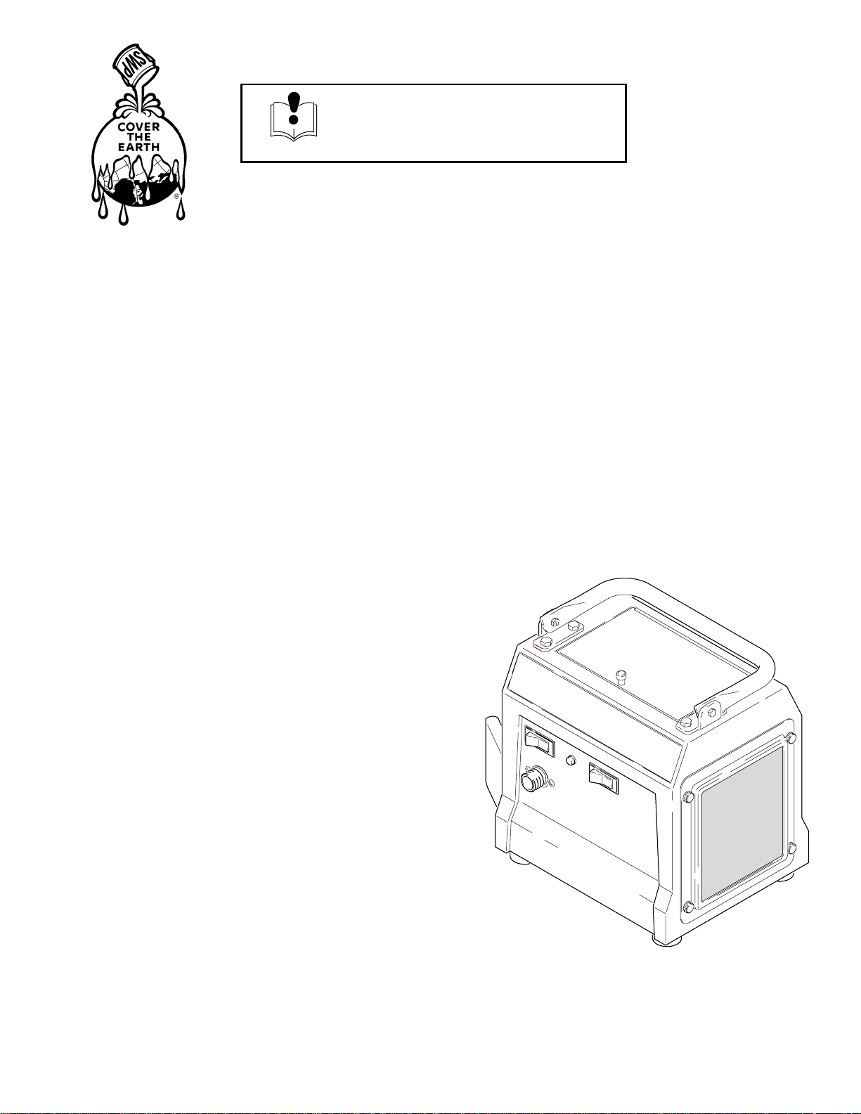
System HVLP Turbine Sprayers
120V AC 50/60 Hz
System 2500 Sprayer with Two-Stage Turbine
Model 826000
5 psi (34 kPa, 0.3 bar) Maximum Working Pressure
System 3800 Sprayer with Three-Stage Turbine
Model 826001
6 psi (41 kPa, 0.4 bar) Maximum Working Pressure
Rev. D
System 4900 Sprayer with Four-Stage Turbine
Model 826004
8 psi (55 kPa, 0.5 bar) Maximum Working Pressure
Model descriptions are in Turbine Components Table on page 4.
Related Manuals
System ProCart 309247. . . . . . . . . . . . . . . . . . . . . . . .
HVLP–Turbine Gun 309205. . . . . . . . . . . . . . . . . . . . . . .
7947A
System 4900t Shown
The SHERWIN–WILLIAMS COMPANY, CLEVELAND, OHIO 44115
COPYRIGHT 2000, GRACO INC.
Page 2
Table of Contents
Symbols
Warnings 2. . . . . . . . . . . . . . . . . . . . . . . . . . . . . . . . . . . . .
General Information 4. . . . . . . . . . . . . . . . . . . . . . . . . . . .
Component Identification and Function 5. . . . . . . . . . . .
Setup 6. . . . . . . . . . . . . . . . . . . . . . . . . . . . . . . . . . . . . . . . .
Shutdown 10. . . . . . . . . . . . . . . . . . . . . . . . . . . . . . . . . . . .
Maintenance 11. . . . . . . . . . . . . . . . . . . . . . . . . . . . . . . . . .
Troubleshooting 13. . . . . . . . . . . . . . . . . . . . . . . . . . . . . . .
Repair 14. . . . . . . . . . . . . . . . . . . . . . . . . . . . . . . . . . . . . . .
Parts Drawing 16. . . . . . . . . . . . . . . . . . . . . . . . . . . . . . . . .
Parts List 17. . . . . . . . . . . . . . . . . . . . . . . . . . . . . . . . . . . . .
Accessories 18. . . . . . . . . . . . . . . . . . . . . . . . . . . . . . . . . .
Specifications 23. . . . . . . . . . . . . . . . . . . . . . . . . . . . . . . . .
Sherwin–Williams Standard Warranty 24. . . . . . . . . . . .
Phone Number 24. . . . . . . . . . . . . . . . . . . . . . . . . . . . . . . .
WARNING
FIRE AND EXPLOSION HAZARD
Improper grounding, poor ventilation, open flames, or sparks can cause a hazardous condition and
result in a fire or explosion and serious injury.
Warning Symbol
WARNING
This symbol alerts you to the possibility of serious
injury or death if you do not follow the instructions.
Caution Symbol
CAUTION
This symbol alerts you to the possibility of damage to
or destruction of equipment if you do not follow the
instructions.
Ground the equipment. See Grounding on page 6.
If there is any static sparking or you feel an electric shock while using this equipment, stop
spraying immediately. Do not use the equipment until you identify and correct the problem.
Provide fresh air ventilation to avoid the buildup of flammable fumes from solvents or the fluid
being sprayed.
When flammable liquid is sprayed or used for flushing or cleaning the equipment, the turbine must
be placed at least 20 feet (6.1 m) away from areas where hazardous concentrations of flammable
vapors are likely to occur.
Use additional air hose if necessary to ensure that the turbine is operated in a clean, dry, well
ventilated area.
Never place the turbine inside a spray booth! Use this equipment outdoors or in extremely well
ventilated areas.
Keep the spray area free of debris, including solvent, rags, and gasoline.
Electrically disconnect all equipment in the spray area.
Extinguish all open flames or pilot lights in the spray area.
Do not smoke in the spray area.
Do not turn on or off any light switch in the spray area while operating or if fumes are present.
Do not operate a gasoline engine in the spray area.
2 309246
Page 3
INSTRUCTIONS
WARNING
EQUIPMENT MISUSE HAZARD
Equipment misuse can cause the equipment to rupture or malfunction and result in serious injury.
This equipment is for professional use only.
Read all instruction manuals, tags, and labels before you operate the equipment.
Use the equipment only for its intended purpose. If you are not sure, call your Graco distributor.
Do not alter or modify this equipment. Use only genuine Graco parts.
Check equipment daily. Repair or replace worn or damaged parts immediately.
Do not exceed the maximum working pressure of the lowest-rated system component.
System 2500 turbine has a working pressure of 5 psi (0.3 bar, 34 kPa).
System 3800 turbine has a working pressure of 6 psi (0.4 bar, 41 kPa).
System 4900 turbine has a working pressure of 8 psi (0.5 bar, 55 kPa).
Use fluids and solvents which are compatible with the equipment wetted parts. See Specifications
on page 23 for wetted parts information.
Do not use hoses to pull equipment.
Route hoses away from traffic areas, sharp edges, moving parts, and hot surfaces. Do not expose
Graco hoses to temperatures above 82C (180F) or below –40C (–40F).
Wear hearing protection when operating this equipment.
Do not lift pressurized equipment.
Comply with all applicable local, state, and national fire, electrical, and safety regulations.
Do not point the gun at anyone or at any part of the body.
Do not put your hand or fingers over the gun fluid nozzle.
Do not stop or deflect leaks with your hand, body, glove or rag.
Do not “blow back” fluid; this is not an air spray system.
Follow the Pressure Relief Procedure on page 10 if the fluid nozzle clogs and before you clean,
check, or service the equipment.
Tighten all fluid connections before you operate the equipment.
Check the hoses, tubes, and couplings daily. Replace worn or damaged parts immediately.
TOXIC FLUID HAZARD
Hazardous fluid or toxic fumes can cause serious injury or death if splashed in the eyes or on the skin,
inhaled, or swallowed.
Know the specific hazards of the fluid you are using.
Store hazardous fluid in an approved container. Dispose of hazardous fluid according to all local,
state, and national guidelines.
Always wear protective eyewear, gloves, clothing and respirator as recommended by the fluid and
solvent manufacturer.
Do not use 1,1,1-trichloroethane, methylene chloride, other halogenated hydrocarbon solvents, or
fluids containing such solvents in the turbine spray system, which contains aluminum and/or
galvanized-coated parts. Such use could result in a serious chemical reaction, with the possibility
of explosion, which could cause death, serious injury, and/or substantial property damage.
309246 3
Page 4

General Information
System HVLP Turbine Sprayers
The System 2500, 3800, and 4900 Sprayer,
System ProCart, and HVLP–Turbine Gun can spray
most coatings or finishes currently being used for
automotive refinish, industrial, aerospace, marine,
wood, plastic, and architectural applications.
To produce high-quality paint finishes, the spray gun
typically utilizes inbound air pressure of 5 psi (0.3 bar,
34 kPa) for System 2500; 6 psi (0.4 bar, 41 kPa) for
System 3800; and 8 psi (0.5 bar, 55 kPa) for
System 4900. A cone of air, produced by the gun,
carries and directs the paint from the gun to the
surface, minimizing overspray and increasing transfer
efficiency. This enables painters to comply with new
clean air laws that are designed to reduce VOC
(volatile organic compounds) emissions, eases paint
application by requiring fewer paint passes to obtain
coverage, and saves on both material and clean-up
time.
See the HVLP–Turbine Gun manual 309205 for more
information on the operation and use of the turbine
spray gun.
Unpacking Turbine Sprayer
Unpack the turbine sprayer from the shipping carton,
and inspect for any possible shipping damage. If there
is any damage, call your distributor.
Turbine Sprayer Configurations
The turbine sprayers come in the following basic
configurations:
System 2500 two-stage HVLP turbine sprayer
System 3800 three-stage HVLP turbine sprayer
System 4900 four-stage HVLP turbine sprayer
System HVLP Turbine Sprayer Components Table
System Model 30-ft (9 m) Hose
2500 826000 241413 244117 non–
3800 826001 241413 244117 non–
4900 826004 241413 244117 non–
Gun /
Fluid Set
bleeder style cup gun/
244124 (#3) fluid set
bleeder style cup gun/
244124 (#3) fluid set
bleeder style cup gun/
244124 (#3) fluid set
Extra/Fluid Sets
none
244125 (#4)
244126 (#5)
244123 (#2)
244125 (#4)
244126 (#5)
244127 (#6)
4 309246
Page 5
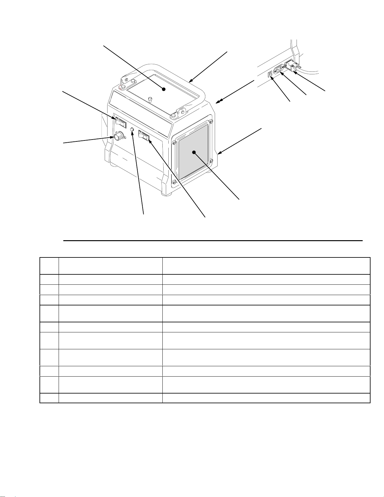
Component Identification and Function
C
B
A
H
G
D
J
K
L
E
F
Fig. 1
A Air outlet Connection for air supply to HVLP–Turbine Guns (System 4900 units
include quick connector)
B Power switch ON/OFF switch for turbine sprayer and rear outlet
C Storage compartment Provides storage for fluid set components
D Handle Folds flat for minimum storage space
E Cover Houses air filter and provides dual air flow to motor and turbine/ can be
lock-mounted on compressor/cart
F Air filters (pre-filter and main) Provide filtered air for HVLP–Turbine Gun and turbine motor
G Two-speed switch Allows two-speed operation of turbine sprayer motor (used on System
4900 units)
H Air filter indicator light Indicates air filter performance and maintenance (used on System
3800 and System 4900 units)
J Connector and power cord Provides power for turbine sprayer (power cord provided with turbine)
K Auxiliary power outlet Switched power outlet for System ProCart or other accessory (used
on System 3800 and System 4900 units)
L Resettable circuit breaker Provides protection for turbine motor and cart
7947A
309246 5
Page 6
Setup
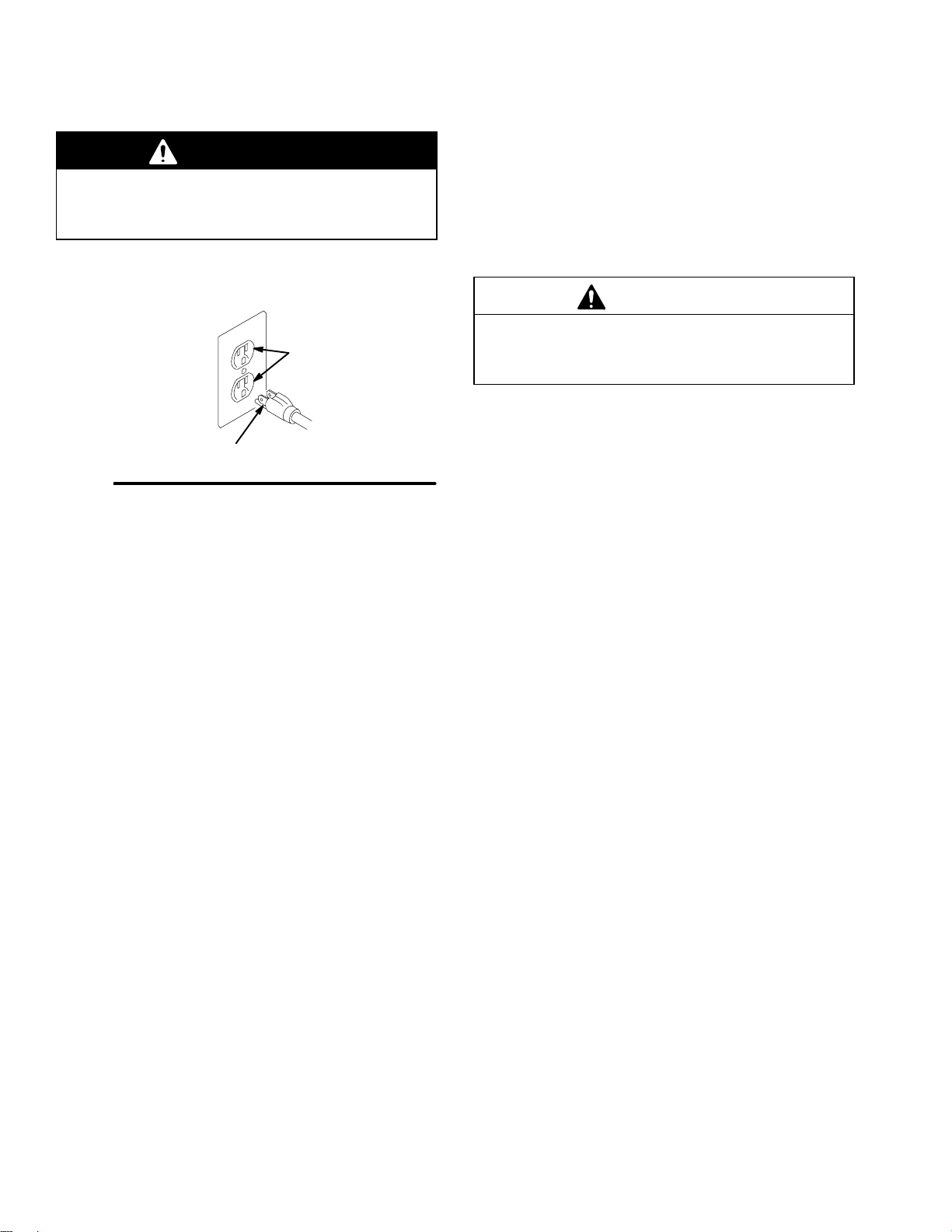
Grounding
WARNING
Improper installation or alteration of the grounding
plug will result in a risk of electric shock, fire or
explosion that could cause serious injury or death.
This equipment requires a 120V AC, 60 Hz, 15A circuit
with a grounding receptacle. See Fig. 2.
grounded outlets
grounding prong
Fig. 2
Extension cord must be 3-wire, 12 AWG, 50 ft (15 m)
or shorter.
Do not alter the ground prong or use an adapter.
Setup/Use Options
System HVLP Turbine Sprayers have a variety of user
options. See Fig. 3.
See the System ProCart manual 309247 for
information on compressor/cart setup and
operation.
Prepare the Fluid
Always strain the fluid before you spray; this
includes color, reducer, and hardeners if used.
When using a System HVLP Turbine Sprayer use a
slower-drying reducer or thinner to compensate for
the faster drying time caused by the warm air of the
turbine. Do not over reduce.
CAUTION
The performance of the turbine sprayer varies with
the viscosity of the material and the length of the
hose. Keep the hose short to prevent pressure drop.
Paint Reduction — Automotive Type Finishes
Reduce and catalyze all paint to manufacturer’s
specifications. To compensate for the faster drying
time of turbine systems, use a reducer that is one step
slower than what is used for conventional air spray.
Paint Reduction — Industrial or Domestic
Coatings
Reduce and catalyze all paint to manufacturer’s
specifications. If no reductions are given, first
thoroughly mix the fluid to be sprayed. Then gradually
mix in the proper reducer, testing the fluid until you
have the correct spraying consistency.
To test the consistency, remove the stir stick from the
thinned paint. When the paint stream running off the
stir stick breaks into droplets, the first few drops should
be about one second apart.
See the HVLP–Turbine Gun manual 309205 for
information on gun setup and operation.
6 309246
Page 7
Setup
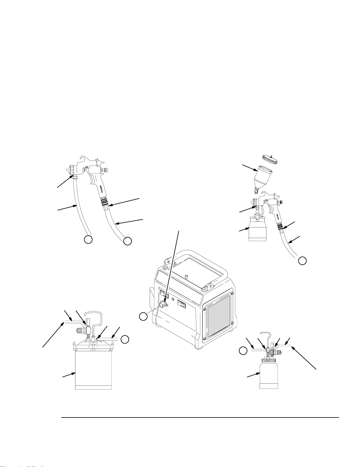
Connect the Fluid and Air Supply
See Fig. 3
The System ProCart provides the air supply for
the remote pressure pot.
The circled letters in Fig. 3 indicate hose line
connections.
1. Connect gun air supply hose (A) between turbine
air outlet (B) and gun air inlet (C). DO NOT use
wrench to tighten connections; hand tighten only.
The System 4900 turbine uses a quick connector
at outlet (B). A wrench is not required for hose
connection.
E
C
2. If using a spray gun cup (D):
connect the cup to the gun fluid inlet (E).
If using accessory remote pressure pot (F):
connect fluid supply hose (G) between remote
pressure pot fluid outlet (H) and gun fluid inlet (E).
Connect pressure pot air hose (J) between
pressure pot air regulator inlet (K) and the
compressor/cart air outlet.
Connect to Electric Supply
Plug turbine power cord into grounded outlet.
NOTE: Extension cord must be 3-wire, 12 AWG, 50 ft
(15 m) or shorter.
D
cup-over option
(see manual 309205)
G
Y
remote pressure pot setup for spray gun
K
J
H
to
compressor/
cart
X
G
Y
F
A
B
X
System 4900t Turbine
E
D
cup setup for spray gun
G
H
Y
F
K
J
compressor/
C
A
X
to
cart
21/2-gallon remote pressure pot
Fig. 3
2-quart remote pressure pot
04958
309246 7
Page 8
Setup
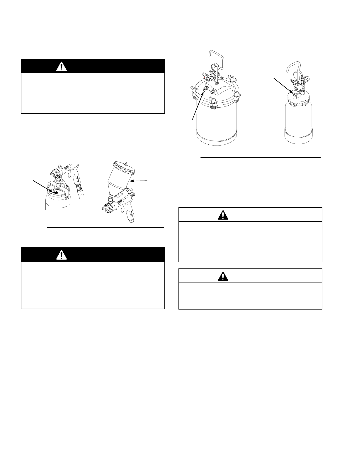
Fill the Cup or Remote Pressure Pot
Spray Gun Cup
WARNING
The spray gun cup is pressurized by the gun’s air
supply. To reduce the risk of serious injury from
pressurized fluid or accidental spray from the gun,
always turn off the air supply to the gun before you
remove the spray gun cup.
Only fill the cup 3/4 full to help keep the air pressure
tube clean, then install the cover. The under-cup cover
has a latch (H) to secure it to the cup. The over-cup (J)
has threads that keep the lid in place when tightened in
place on the cup.
206c
Fig. 5
21/
gallon
2
8069A
113
2 quart
02882A
H
Fig. 4
Accessory Remote Pressure Pot
J
WARNING
The accessory remote pressure pots remain pressurized until pressure is manually relieved. To
reduce the risk of serious injury from pressurized
fluid or accidental spray from the gun, always
relieve pressure in the pressure pot before you
loosen or remove the cover.
1. Relieve remote pressure pot pressure as follows
(see Fig. 5):
a. Turn off air supply to pressure pot.
02845
2. Remove pressure pot cover and fill. Secure cover.
NOTE: 2-quart remote pressure pot only:
Lightly coat the cover threads with petroleum jelly.
CAUTION
If the 2-quart remote pressure pot is accidentally
tipped over or held at too great of an angle, fluid may
leak into the air regulator and cause damage. Take
precautions to avoid this. If fluid does get into the
regulator, clean it immediately.
CAUTION
Do not tighten the pressure pot cover more than
hand-tight. Excessive tightening may damage the
cover gasket.
b. 21/2-gallon remote pressure pot:
Pull pressure relief valve ring (206c) until
pressure is completely relieved.
2-quart remote pressure pot:
Turn out pressure relief knob (113) one turn.
Wait until pressure is completely relieved
before you remove cover. Close knob.
8 309246
Page 9

Setup
Prepare Surface to be Sprayed
To get proper adhesion, make sure surface is
completely clean.
Operating System HVLP Turbine Sprayer
WARNING
Sparks can be expected in the normal operation of
the turbine motor. These sparks can ignite fumes
from flammable liquids, dust particles, and other
flammable substances in the spray area. This can
cause serious injury and property damage. Be sure
to follow the precautions below:
When flammable liquid is sprayed or used for
flushing or cleaning equipment, the turbine must
be placed at least 20 feet (6.1 m) away from
areas where hazardous concentrations of
flammable vapors are likely to occur.
Use additional air hose if necessary to ensure
that the turbine is operated in a clean, dry, well
ventilated area.
System ProCartt Cold Weather Operation
The System ProCart uses a diaphragm compressor.
A new diaphragm may be stiff in cold weather. If cold
enough, the diaphragm is too stiff to allow the
compressor motor to start (the unit hums). If this
occurs, follow these steps:
1. Turn turbine and compressor OFF.
2. Unplug turbine from power source.
3. Pinch and remove filter by hand. Clean or replace
if dirty.
4. Hand spin cooling fan on compressor for a few
revolutions.
5. Reinstall filter.
6. Plug in turbine.
7. Turn turbine and compressor ON. If necessary,
repeat procedure.
Never place the turbine inside a spray booth!
Use this equipment outdoors or in extremely
well ventilated areas.
Avoid all ignition sources such as: static elec-
tricity from plastic drop cloths, open flames like
pilot lights, hot objects like cigarettes, arcs from
connecting or disconnecting power cords, and
turning light switches on and off. Extinguish or
remove all sources of ignition.
1. Turn turbine ON a few minutes before spraying to
allow warm-up.
NOTE: When the turbine is not in use for an extended
period of time, turn it off. The turbine does not shut off
automatically.
2. Be sure turbine filter is clean before operating. See
page 11 to check and clean filter.
NOTE: To adjust the spray gun pattern, see the
HVLP–Turbine Gun manual 309205.
309246 9
Page 10

Shutdown
Pressure Relief Procedure
WARNING
PRESSURIZED EQUIPMENT HAZARD
The equipment stays pressurized until pressure is
manually relieved. To reduce the risk of a serious
injury from pressurized fluid, accidental spray from
the gun, or splashing fluid, follow the Pressure
Relief Procedure whenever you
Are instructed to relieve the pressure
Stop spraying
Check or service any of the system equipment
Install or clean the fluid nozzles
1. Turn off air supply to gun.
2. Turn off turbine sprayer.
WARNING
The turbine hose outlet may be hot. Carefully check
the hose end before you remove the hose.
3. If using remote pressure pot, relieve pressure by
following these steps (see Fig. 6):
a. Turn off air supply to pressure pot.
113
21/
gallon
206c
Fig. 6
NOTE: Elevate spray gun and pull trigger. This will
allow fluid in fluid hose to drain back into remote
pressure pot.
4. If using a spray gun cup:
Unlatch cup cover, and loosen or remove cup from
cover to relieve cup pressure.
5. Clean spray gun and cup as instructed in
HVLP–Turbine Spray Gun manual 309205.
2
8069A
2 quart
02882A
b. 21/2-gallon remote pressure pot:
Pull pressure relief valve ring (206c) until
pressure is completely relieved.
2-quart remote pressure pot:
Turn out pressure relief knob (113) one turn.
Wait until pressure is completely relieved
before you remove cover. Close knob.
10 309246
Page 11

Maintenance
Daily
The System HVLP Turbine Sprayers are lifetime
lubricated. The only maintenance required is filter
cleaning and replacement.
The turbine filter must be clean at all times to provide
sufficient air flow to cool motor and atomize the fluid.
Check turbine pre-filter (22) daily for cleanliness.
Check the main paper filter (21) weekly, minimum.
Clean as necessary.
NOTE: To check filter, turn on turbine and place piece
of paper against pre-filter. If air intake holds paper in
place, filter is okay.
System 3800 and System 4900 models have an
air filter indicator light on the front panel. If the filter is
good the light is out. If the filter is clogged or has low
airflow the light will come on as in Fig. 7 below.
WARNING
To avoid damage to the turbine and possible electric shock, never install a damp filter in the turbine.
CAUTION
To keep out dirt, do not operate the turbine sprayer
without both filters installed.
1
20
21
22
16
Fig. 7
8049A
To clean filter:
1. Turn off and unplug turbine.
2. Loosen four thumbscrews (16), and remove filter
retainer (15) and pre-filter (22). See Fig. 8.
3. Remove main filter (21) and clean by using one of
the following three methods:
Tap filter gently on flat surface, dirty side
down.
CAUTION
To prevent damage to filter, do not use compressed
air on a wet filter.
Direct compressed air (100 psi [7 bar, 70 kPa]
maximum) through filter panel in opposite
direction of arrows on side of filter (from the
clean side to the dirty side).
Fig. 8
15
03072
Weekly
Check hose for cracks, leaks, and holes. Replace if
necessary.
Annually or Every 600 Hours, Whichever
Comes First
Replace motor brushes 600 hours after turbine sprayer
operation. If brushes are not replaced, motor failure
will occur.
NOTE: It is recommended that an authorized service
center perform the motor brush replacement procedure
on page 14.
Soak filter for 15 minutes in water and mild
detergent. Rinse filter until clean. Air dry. Do
not use compressed air on damp or wet filter.
309246 11
Page 12

Notes
12 309246
Page 13

Troubleshooting
PROBLEM CAUSE SOLUTION
No fluid delivery No material, no remote
container pressurization, hose
or pickup tube clogged
Compressor not
starting
Cold weather operation See System ProCartt Cold Weather Operation on
Check container for material.
Check for leaks at the container gasket (2-quart
pressure pot cover or 21/2-gallon pressure pot wing
nuts). Tighten wing nuts if loose.
Check for air flow from male quick disconnect at
compressor outlet (should be approx. 1/4 CFM).
Turn pressure regulator clockwise. Look for pressure
on gauge. (If no pressure on gauge, check air line and
fittings).
Check hole in 21/2-gallon pressure pot cover under
regulator or in 2-quart pressure pot cover at needle
valve. Clean if necessary.
Check for obstructions.
Check if fluid pickup tube is unplugged. Tighten.
Blow out and clear material hose.
page 9.
Turbine not starting No power Check outlet for power. Cycle red rocker switch.
Check that correct IEC (modular) cord is used and
plugged in.
Check circuit breaker(38). Push to reset.
Poor atomization Dirty filter Clean filter.
Extension cord too long Extension cord must be 3-wire, 12 AWG, 50 ft (15 m)
or shorter.
Hose too long Replace with shorter hose.
Circuit breaker trips Filter clogged Clean filter and replace as necessary.
High ambient temperature Move turbine to cooler area.
Excessive brush wear Remove cover and turbine, and check for free motor
rotation and for brush wear. Replace motor brushes if
necessary.
Excessive current draw Return to authorized service center.
309246 13
Page 14

Repair
WARNING
Turn off turbine and unplug power for the following
procedures.
System HVLP Turbine Sprayer
Disassembly
1. If necessary, clean and replace filter according to
maintenance procedure on page 11.
Motor Brush Replacement
NOTE: It is recommended that this procedure be
performed by an authorized service center.
1. Use System HVLP Turbine Sprayer
Disassembly procedure on page 14 to take
turbine apart. Use Turbine/Motor Replacement
on page 15 to replace turbine.
2. Remove plastic fan cover.
2. Place turbine upside down on work surface.
Remove four cap screws (27) and bumpers (7).
See Fig. 9.
3. Carefully lift unit by turbine baseplate (2) from
turbine cover (1), and place upright on work
surface.
4. Repair or replace items as required.
5. Reassemble turbine.
27
7
2
3. Remove brushes. Check commutator for
excessive wear.
Note: Do not install new brushes in a turbine that has
had brush holders damage the commutator. A motor
with this type of commutator damage is unrepairable.
4. Install new motor brushes using reverse order.
Keep lead wires from all rotating parts and motor
frame.
CAUTION
Do not run the motor with the air inlet or outlet
sealed off.
5. Reassemble turbine.
1
6. Run motor 30 to 45 minutes at half-rated voltage
to seat motor brushes.
Note: If half-rated voltage is not available, run repaired
unit in series with another turbine for 30 to 45 minutes.
A
Fig. 9
7949A
Power Cord Replacement
Replace power cord by unplugging from IEC connector
(A). Install new cord. See Fig. 9
14 309246
Page 15

Turbine/Motor Replacement
The System 2500, System 3800, and System
4900 Turbine Sprayers each use a different
turbine/motor. See the Turbine/Motor Replacement
Kits in the Parts List on page 17 for a listing of
replacement kit parts.
See parts drawing on page 17.
1. Use System HVLP Turbine Sprayer
Disassembly procedure on page 14 to take
turbine apart.
2. Remove turbine gasket (25).
3. Loosen 3 screws (6) and remove.
4. Remove plate (82) and 3 spacers (83).
5. Remove turbine motor wires from spade
connectors.
Repair
Motor
6. Rotate turbine (24) from outlet fitting (18) and lift
up from turbine spacers (23).
7. Install new turbine gaskets (25 and 41).
8. Reassemble turbine.
9. Connect ground wire to turbine housing as
required.
10. Reconnect wires according to applicable turbine.
See Fig. 10, Fig. 11, or Fig. 12 schematics.
Motor
G
L1
L2
Fig. 11
System 3800t
7245A
Motor
Fig. 10
GROUND
N
System 2500t
System 4900t
Fig. 12
L
G
7244B
309246 15
Page 16

13
Parts Drawing
81
29
1
19
18
14
25
82
24
4
46
27
28
6
83
23
26
6
20
21
22
15
16, 17
34
16 309246
33
47
31
32, 40
42
41
5
11
10
39
36
2
69
6
3
12
65
12
38
67
68
7
27
37
4
7943C
Page 17

Parts List
Ref
No. Part No. Description Qty
1 276674 COVER, turbine 1
2 197111 BASE PLATE, turbine
(System 2500)1
192775 BASE PLATE, turbine
(System 3800)1
192774 BASE PLATE, turbine
(System 4900)1
3 192786 PLATE, retaining (System 3800
and System 4900)1
4 114669 SCREW, pan hd 4
5 192787 DUCT, turbine 1
6 114670 SCREW, cap, hx hd 8
7 113817 BUMPER 4
10 114064 PLUG, inlet 1
11 114065 PLUG, inlet, female (System 3800
and System 4900)1
12 114410 SCREW, pan hd, torx 6
13 244166 LID, tool box 1
14 197054 FOAM PAD, tool box 1
15 197057 RETAINER, filter 1
16 192895 SCREW, captive 4
17 158486 O-RING 4
18 193057 FITTING, outlet (System 2500)1
192779 FITTING, outlet (System 3800
and System 4900)1
19 156698 O-RING, buna–n 1
20 192789 GASKET, filter (System 3800
and System 4900)2
21 240273 FILTER, main, paper (System
3800 and System 4900)1
244137 FILTER, main, foam (System
2500)1
22† 240274 FILTER, pre 1
23 193068 SPACER, turbine (System 2500)3
192780 SPACER, turbine (System
3800 and System 4900)3
24* 240269 TURBINE KIT, 2 stage; 120 volts
(System 2500)1
240270 TURBINE KIT, 3 stage; 120 volts
(System 3800)1
241122 TURBINE KIT, 4 stage; 120 volts
(System 4900)1
25 192812 GASKET, turbine (System 2500)1
192788 GASKET, turbine (System
3800 and System 4900)1
26 192784 BRACKET, handle 2
27 114531 SCREW, cap, hx hd 8
28 113414 NUT, lock 2
29 192785 HANDLE, turbine 1
31 114658 SWITCH, rocker (System 4900)1
Ref
No. Part No. Description Qty
32 114279 SENSOR, pressure (System
3800 and System 4900)1
33 114280 LIGHT, indicator (System 3800
and System 4900)1
34 114293 SWITCH, rocker, red 1
36 111593 SCREW, grounding 1
37 102063 WASHER, lock, external tooth 1
38 114290 BREAKER, circuit; 8A, 120V
(System 2500)1
114403 BREAKER, circuit; 15A, 120V
(System 3800 and
System 4900)1
39 192905 PLATE, deflector (System
3800 and System 4900)1
40 193059 GASKET, sensor (System
3800 and System 4900)1
41 192845 GASKET, duct 1
42 192846 GASKET, duct 1
46 114287 FITTING, barbed (System
3800 and System 4900)1
47 192810 HOSE, air (System
3800 and System 4900)1
65 245202 CORD SET, 10 ft, 13 AMP, 120V
(System 2500 & System 3800)1
240281 CORD SET, 15 ft, 15 AMP, 120V
(System 4900)1
67 193095 LABEL, danger 1
68 193096 LABEL, warning 1
69 193126 LABEL, caution 1
75 244122 #2/4/5/6 ACCESSORY KIT
(System 4900) Not shown 1
81 114538 SCREW, mach, pan hd 2
82 194094 PLATE, turbine 1
83 SPACER, turbine
194095 System 2500 3
194096 System 3800 3
194097 System 4900 3
† Pre-filters are available in 5 packs. Order Part No.
240274.
* Turbine Brush Kits are also available. Purchase
separately: 240545 (for System 2500),
and 240546 (for System 3800 and System
4900).
Extra danger and warning labels are available
for free.
309246 17
Page 18

Accessories
21/2-Gallon (9.5 liter) PTFE coated Pot 240045
50 psi (345 kPa, 3.5 bar) Maximum Inlet Air Pressure
21/2-gallon (9.5 liter) capacity, steel tank. Includes air
pressure regulator, gauge, and pressure relief valve.
201
216
217
221
208
209
203
202
212
207
204
205
21/2-gal (9.5 liter)
paint tank liner
(5 pack) 112077
212
2-Quart (1.9 liter) Pressure Pot M70962
50 psi (345 kPa, 3.5 bar) Maximum Inlet Air Pressure
2-quart (1.9 liter) capacity, aluminum cup.
Includes air pressure regulator, gauge, pressure relief
valve, and rigid hook handle.
WARNING
Do not use 1,1,1-trichloroethane, methylene chloride, other halogenated hydrocarbon solvents, or
fluids containing such solvents in the turbine spray
system, which contains aluminum and/or galvanized-coated parts. Such use could result in a
serious chemical reaction, with the possibility of
explosion, which could cause death, serious injury,
and/or substantial property damage.
124
120
121
119
*109
118
114
101
103
102
123
122
128
04957
Ref.
No. Part No. Description Qty.
201 104655 PRESSURE GAUGE 1
202 151519 REDUCER, 1/4 to 1/8 1
203 M70687 COUPLING 1
204 M70676 O-RING 1
205 M70686 PRESSURE RELIEF VALVE 1
207 M70616 GASKET, standard; EPDM 1
M70617 GASKET, solvent resistant; Thiokol
(optional — must order separately) 1
208 M70678 WING NUT 5
209 M70677 WASHER 5
212 244288 TANK, paint, 2
with PTFE coat 1
216 169969 QUICK DISCONNECT, male 1
217 104815 PRESSURE REGULATOR 1
221 M71639 HANDLE 1
1
/2-gal (9.5 liter),
109
126
112
(Handle is
shipped loose,
inside of 2-qt
container.)
127
02951A
Ref.
No. Part No. Description Qty.
101 104655 PRESSURE GAUGE 1
102 M70727 SAFETY VALVE 1
103 104815 PRESSURE REGULATOR 1
109 M71144 POT, 2 quart (1.9 liter), aluminum 1
112 M71425 GASKET KIT, polyethylene (5 pak) 1
114 M70725 FITTING 1
118 169969 QUICK DISCONNECT, male 1
119 M71491 HOSE, fluid; 60 in. long; 1/4 in. ID 1
120 240063 HOSE, air; 54 in. (1.37 m) long 1
121 M70854 HOSE CLAMP 1
122 110440 FITTING. tee 1
123 189557 RESTRICTOR 1
124 M70399 QUICK DISCONNECT, male 1
126 M71681 AIR VALVE KIT (o-ring and valve) 1
127 M70402 QUICK DISCONNECT 1
128 M72842 FITTING, air pressure stem 1
18 309246
Page 19

Accessories
Notes:
See HVLP Fine Finish Systems
brochure 300564 for all accessories.
Non-Silicone Lubricant 111265 (4 oz) is
available for fluid seals and wear areas.
Fluid Set (FS)/Spray Gun
FS Number
None
3 244118
244115
Tie Wrap Kit
(10 pack)
103473
Standard Turbine Air Hose
Length (ft) Number
30 241413
Material Hose
Length (ft) Number
30
240476
Air & Material Hose
Length (ft) Number
30 241423
Pressure Pot
PTFE Lined 240045
8483A
Compressor Air Hose
Pot Length (ft) Number
21/
2
gal
2 qt 30
2 240074
240071
309246 19
Page 20

Accessories
21/2-Gallon (9.5 liter) PTFE coated Pot 240045
50 psi (345 kPa, 3.5 bar) Maximum Inlet Air Pressure
21/2-gallon (9.5 liter) capacity, steel tank. Includes air
pressure regulator, gauge, and pressure relief valve.
216
217
202
212
204
205
21/2-gal (9.5 liter)
paint tank liner
(5 pack) 112077
201
221
207
212
208
209
203
Ref.
No. Part No. Description Qty.
201 104655 PRESSURE GAUGE 1
202 151519 REDUCER, 1/4 to 1/8 1
203 M70687 COUPLING 1
204 M70676 O-RING 1
205 M70686 PRESSURE RELIEF VALVE 1
207 244953 GASKET, standard;
polyethylene (3/kit) 1
M70616 GASKET, standard; EPDM
(optional – must order separately 1/kit) 1
M70617 GASKET, solvent resistant; 1
208 M70678 WING NUT 5
209 M70677 WASHER 5
212 244288 TANK, paint, 2
with PTFE coat 1
216 169969 QUICK DISCONNECT, male 1
217 104815 PRESSURE REGULATOR 1
221 M71639 HANDLE 1
1
/2-gal (9.5 liter),
04957
20 309246
Page 21

Accessories
2-Quart (1.9 liter) Pressure Pot 287300
50 psi (345 kPa, 3.5 bar) Maximum Inlet Air Pressure
2-quart (1.9 liter) capacity, aluminum cup.
Includes air pressure regulator, gauge, pressure relief
valve, and rigid hook handle.
WARNING
Do not use 1,1,1-trichloroethane, methylene chloride, other halogenated hydrocarbon solvents, or
fluids containing such solvents in the turbine spray system, which contains aluminum and/or
galvanized-coated parts. Such use could result in a serious chemical reaction, with the possibility
of explosion, which could cause death, serious injury, and/or substantial property damage.
Ref.
No. Part No. Description Qty.
101 104655 PRESSURE GAUGE 1
103 104815 PRESSURE REGULATOR 1
109 287302 POT, 2 quart (1.9 liter), aluminum 1
112 15F346 GASKET KIT 1
287404 GASKET KIT 5–pack 1
114 169969 FITTING 1
119 240474 HOSE, fluid; 60 in. long; 1/4 in. ID 1
120 240482 HOSE, air; 54 in. (1.37 m) long 1
121 M70854 HOSE CLAMP 1
123 189557 RESTRICTOR 1
124 M70399 QUICK DISCONNECT, male 1
127 M70402 QUICK DISCONNECT 1
244135 KIT, valve, duckbill (not shown) 1
193218 STRAINER (not shown) 1
128 15D744 LIT KIT, Series A 1
15F620 LID KIT, Series B 1
129 119216 VALVE KIT, check repair, Series A 1
15F610 VALVE KIT, check repair, Series B
130 119212 HANDLE, Series A 1
15F606 HANDLE, Series B 1
131 119213 NUT, handle, Series A 1
15F607 NUT, handle, Series B 1
132 119214 NUT, cover, Series A 1
15F608 NUT, cover, Series B 1
133 119215 VALVE, Series A 1
15F609 VALVE, Series B 1
134 119217 FITTING, outlet, Series A 1
15F611 FITTING, outlet, Sereis B 1
135 119218 COVER Series A 1
15F612 COVER, Series B 1
136 119220 TUBE, fluid, Series A 1
15F613 TUBE, fluid, Series B 1
137 119221 CUP, 2 quart, Series A 1
15F614 CUP, 2 quart, Series B 1
NOTE:
See HVLP Finish Systems brochure 300564 for all
accessories.
Non–silicone lubricant 111265 (4 oz.) is available
for fluid seals and wear areas.
127
120
124
135
130
121
132
112
137
131
133
119
136
134
109
114
101 103
123
128
129
109 (handle is
shipped loose,
inside 2–qt
container)
0295D
309246 21
Page 22

Accessories
Lubricant
One, 4–ounce (113 gram) tube sanitary (non–silicone)
lubricant for fluid seals and wear areas.
1–Quart Under–Cup Assembly 244130
Complete 1–quart under–cup assembly.
1–Quart Cup and Lid 244131
1–quart under–cup with lid for air–tight storage of fluid.
1–Quart Cup 244132
1–quart under–cup.
1–Quart Cup Gaskets 240265
5–pack of polyethylene gaskets for use with 1–quart
under–cup.
Fluid Strainer (3 each) 240267
Install on the end of the cup to strain the fluid and help
eliminate surface blemishes and plugged tips. 100
mesh screen.
User Kit #2 and #4 244122
Contains #2 and #
Y Fitting Kit 240069
Creates two air connections; allows for two–gun
operation.
22 309246
Page 23

Specifications
Power requirements 120V AC, 50/60 Hz. . . . . . . . . . . . . . . . . . . . . . . . . . . . . . . . . . . . . . . . . . . . . . . . . . . . . . . . . . . . . . . . .
Amps at 120 volts
System 2500 1 phase, 7A minimum. . . . . . . . . . . . . . . . . . . . . . . . . . . . . . . . . . . . . . . . . . . . . . . . . . . . . . . . . . . . . . . . .
System 3800 1 phase, 12A minimum. . . . . . . . . . . . . . . . . . . . . . . . . . . . . . . . . . . . . . . . . . . . . . . . . . . . . . . . . . . . . . . .
System 4900 1 phase, 14A minimum. . . . . . . . . . . . . . . . . . . . . . . . . . . . . . . . . . . . . . . . . . . . . . . . . . . . . . . . . . . . . . . .
Power cord (extension cord must be 3-wire, 12 AWG, 50 ft [15 m] or shorter)
System 2500 No. 16 AWG, 3 wire, 10 ft. . . . . . . . . . . . . . . . . . . . . . . . . . . . . . . . . . . . . . . . . . . . . . . . . . . . . . . . . . . . . .
System 3800 No. 16 AWG, 3 wire, 10 ft. . . . . . . . . . . . . . . . . . . . . . . . . . . . . . . . . . . . . . . . . . . . . . . . . . . . . . . . . . . . . .
System 4900 No. 14 AWG, 3 wire, 15 ft. . . . . . . . . . . . . . . . . . . . . . . . . . . . . . . . . . . . . . . . . . . . . . . . . . . . . . . . . . . . . .
Unrestricted flow rate
System 2500 58 cfm. . . . . . . . . . . . . . . . . . . . . . . . . . . . . . . . . . . . . . . . . . . . . . . . . . . . . . . . . . . . . . . . . . . . . . . . . . . . . .
System 3800 80 cfm. . . . . . . . . . . . . . . . . . . . . . . . . . . . . . . . . . . . . . . . . . . . . . . . . . . . . . . . . . . . . . . . . . . . . . . . . . . . . .
System 4900 82 cfm. . . . . . . . . . . . . . . . . . . . . . . . . . . . . . . . . . . . . . . . . . . . . . . . . . . . . . . . . . . . . . . . . . . . . . . . . . . . . .
Turbine stages
System 2500 2. . . . . . . . . . . . . . . . . . . . . . . . . . . . . . . . . . . . . . . . . . . . . . . . . . . . . . . . . . . . . . . . . . . . . . . . . . . . . . . . . . .
System 3800 3. . . . . . . . . . . . . . . . . . . . . . . . . . . . . . . . . . . . . . . . . . . . . . . . . . . . . . . . . . . . . . . . . . . . . . . . . . . . . . . . . . .
System 4900 4. . . . . . . . . . . . . . . . . . . . . . . . . . . . . . . . . . . . . . . . . . . . . . . . . . . . . . . . . . . . . . . . . . . . . . . . . . . . . . . . . . .
Maximum turbine hose length
System 2500 40 ft (12 m). . . . . . . . . . . . . . . . . . . . . . . . . . . . . . . . . . . . . . . . . . . . . . . . . . . . . . . . . . . . . . . . . . . . . . . . . .
System 3800 60 ft (18 m). . . . . . . . . . . . . . . . . . . . . . . . . . . . . . . . . . . . . . . . . . . . . . . . . . . . . . . . . . . . . . . . . . . . . . . . . .
System 4900 60 ft (18 m). . . . . . . . . . . . . . . . . . . . . . . . . . . . . . . . . . . . . . . . . . . . . . . . . . . . . . . . . . . . . . . . . . . . . . . . . .
Cup volume 1 quart (0.95 liter). . . . . . . . . . . . . . . . . . . . . . . . . . . . . . . . . . . . . . . . . . . . . . . . . . . . . . . . . . . . . . . . . . . . . . . . . .
Wetted parts
Bare spray gun stainless steel, brass, PTFE, hard-coated aluminum. . . . . . . . . . . . . . . . . . . . . . . . . . . . . . . . . . . . . . .
Spray gun cup aluminum, polyethylene. . . . . . . . . . . . . . . . . . . . . . . . . . . . . . . . . . . . . . . . . . . . . . . . . . . . . . . . . . . . . . . .
2-quart (1.9 liter) accessory remote pressure pot aluminum, brass, polyethylene. . . . . . . . . . . . . . . . . . . . . . . . . . . .
1
/2-gallon (9.5 liter) accessory remote pressure pot steel with solvent-resistant finish,. . . . . . . . . . . . . . . . . . . . . . .
2
EPDM gasket (standard)
Turbine shipping weight
System 2500 32 lb (14.5 kg). . . . . . . . . . . . . . . . . . . . . . . . . . . . . . . . . . . . . . . . . . . . . . . . . . . . . . . . . . . . . . . . . . . . . . . .
System 3800 34 lb (15.4 kg). . . . . . . . . . . . . . . . . . . . . . . . . . . . . . . . . . . . . . . . . . . . . . . . . . . . . . . . . . . . . . . . . . . . . . . .
System 4900 36 lb (17.7 kg). . . . . . . . . . . . . . . . . . . . . . . . . . . . . . . . . . . . . . . . . . . . . . . . . . . . . . . . . . . . . . . . . . . . . . . .
Turbine diameter 5.7 in (144.78 mm). . . . . . . . . . . . . . . . . . . . . . . . . . . . . . . . . . . . . . . . . . . . . . . . . . . . . . . . . . . . . . . . . . . . .
Sound level per ISO 3744
Sound power level 89.0 dB(A). . . . . . . . . . . . . . . . . . . . . . . . . . . . . . . . . . . . . . . . . . . . . . . . . . . . . . . . . . . . . . . . . . . . . . . . .
Sound pressure level 78.0 dB(A). . . . . . . . . . . . . . . . . . . . . . . . . . . . . . . . . . . . . . . . . . . . . . . . . . . . . . . . . . . . . . . . . . . . . .
309246 23
Page 24

Sherwin-Williams Standard Warranty
Graco warrants all equipment referenced in this document which is manufactured by Graco and bearing its name to be free from
defects in material and workmanship on the date of sale by an authorized Graco distributor to the original purchaser for use. With the
exception of any special, extended, or limited warranty published by Graco, Graco will, for a period of twelve months from the date of
sale, repair or replace any part of the equipment determined by Graco to be defective. This warranty applies only when the equipment
is installed, operated and maintained in accordance with Graco’s written recommendations.
This warranty does not cover, and Graco shall not be liable for general wear and tear, or any malfunction, damage or wear caused by
faulty installation, misapplication, abrasion, corrosion, inadequate or improper maintenance, negligence, accident, tampering, or
substitution of non-Graco component parts. Nor shall Graco be liable for malfunction, damage or wear caused by the incompatibility of
Graco equipment with structures, accessories, equipment or materials not supplied by Graco, or the improper design, manufacture,
installation, operation or maintenance of structures, accessories, equipment or materials not supplied by Graco.
This warranty is conditioned upon the prepaid return of the equipment claimed to be defective to an authorized Graco distributor for
verification of the claimed defect. If the claimed defect is verified, Graco will repair or replace free of charge any defective parts. The
equipment will be returned to the original purchaser transportation prepaid. If inspection of the equipment does not disclose any defect
in material or workmanship, repairs will be made at a reasonable charge, which charges may include the costs of parts, labor, and
transportation.
THIS WARRANTY IS EXCLUSIVE, AND IS IN LIEU OF ANY OTHER WARRANTIES, EXPRESS OR IMPLIED, INCLUDING BUT
NOT LIMITED TO WARRANTY OF MERCHANTABILITY OR WARRANTY OF FITNESS FOR A PARTICULAR PURPOSE.
Graco’s sole obligation and buyer’s sole remedy for any breach of warranty shall be as set forth above. The buyer agrees that no other
remedy (including, but not limited to, incidental or consequential damages for lost profits, lost sales, injury to person or property, or any
other incidental or consequential loss) shall be available. Any action for breach of warranty must be brought within two (2) years of the
date of sale.
GRACO MAKES NO WARRANTY, AND DISCLAIMS ALL IMPLIED WARRANTIES OF MERCHANTABILITY AND FITNESS FOR
A PARTICULAR PURPOSE, IN CONNECTION WITH ACCESSORIES, EQUIPMENT, MATERIALS OR COMPONENTS SOLD
BUT NOT MANUFACTURED BY GRACO. These items sold, but not manufactured by Graco (such as electric motors, switches,
hose, etc.), are subject to the warranty, if any, of their manufacturer. Graco will provide purchaser with reasonable assistance in
making any claim for breach of these warranties.
In no event will Graco be liable for indirect, incidental, special or consequential damages resulting from Graco supplying equipment
hereunder, or the furnishing, performance, or use of any products or other goods sold hereto, whether due to a breach of contract,
breach of warranty, the negligence of Graco, or otherwise.
FOR GRACO CANADA CUSTOMERS
The parties acknowledge that they have required that the present document, as well as all documents, notices and legal proceedings
entered into, given or instituted pursuant hereto or relating directly or indirectly hereto, be drawn up in English. Les parties
reconnaissent avoir convenu que la rédaction du présente document sera en Anglais, ainsi que tous documents, avis et procédures
judiciaires exécutés, donnés ou intentés à la suite de ou en rapport, directement ou indirectement, avec les procedures concernées.
ADDITIONAL WARRANTY COVERAGE
Graco does provide extended warranty and wear warranty for products described in the “Graco Contractor Equipment Warranty
Program”.
Phone Number
TO PLACE AN ORDER, contact your Graco distributor, or call this number to identify the distributor closest to you:
1–800–690–2894 Toll Free
All written and visual data contained in this document reflect the latest product information available at the time of publication.
Graco reserves the right to make changes at any time without notice.
The SHERWIN–WILLIAMS COMPANY, 101 PROSPECT AVENUE, CLEVELAND, OHIO 44115
PRINTED IN USA 309246 November 2000, Revised January 2005
24 309246
 Loading...