

Page 1
Instructions
®
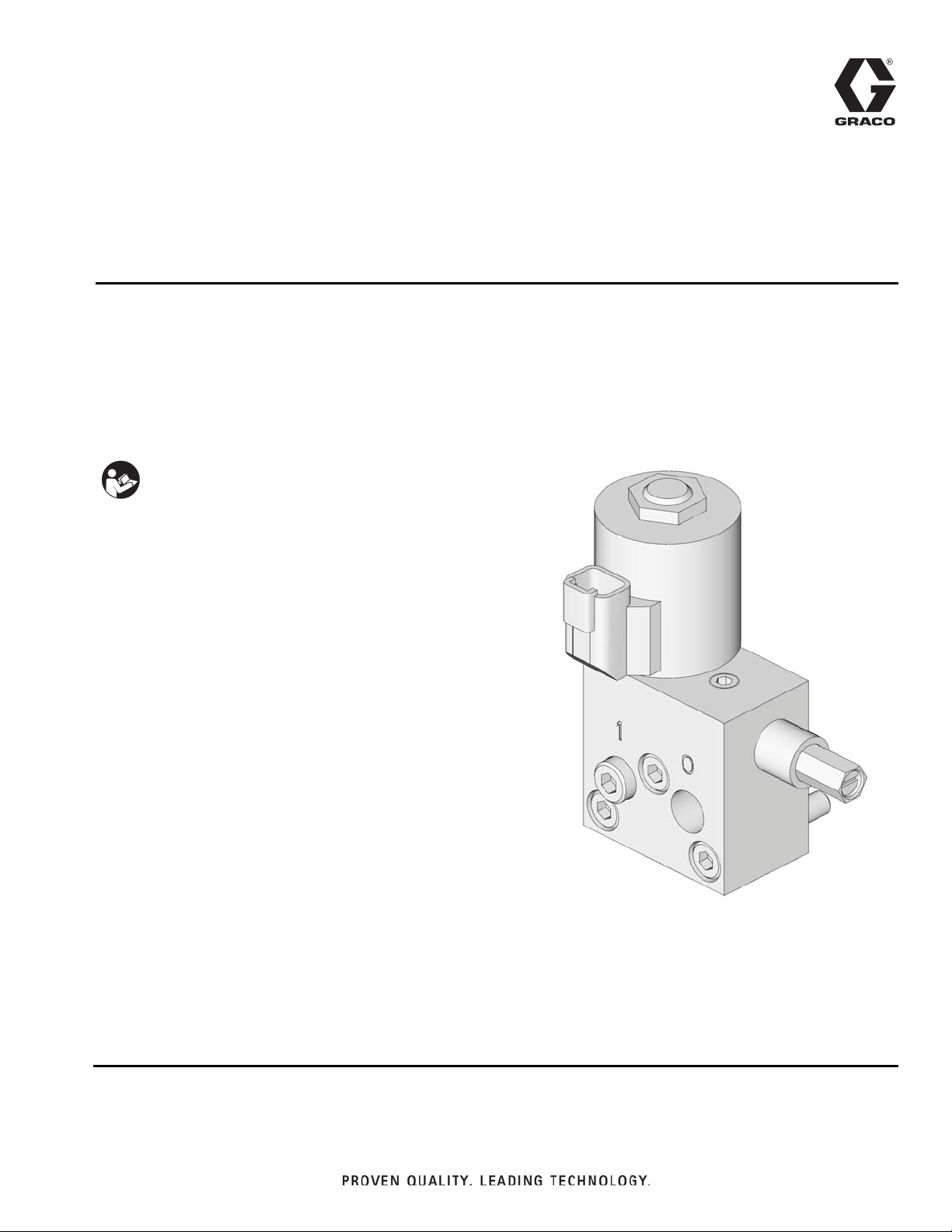
Dyna-Star
HP Vent
332519F
Valve Kit
Used with the Dyna-Star HP or HF Pump to reduce system pressure and allow injector to
reset. For professional use only.
Part No.: 77X540
Maximum Working Pressure: 3500 psi (241 bar, 24 MPa)
Important Safety Instructions
Read all warnings and instructions in this
manual and the Dyna-Star HP and HF Pump
instruction manual included with your unit. Save
all instructions.
EN
Page 2
Instructions
Instructions
Warnings
See the Dyna-Star HF and HP Pump Instruction manual
for additional warnings.
SKIN INJECTION HAZARD
High-pressure fluid from dispense device, hose leaks,
or ruptured components will pierce skin. This may look
like just a cut, but it is a serious injury that can result in
amputation. Get immediate surgical treatment.
Follow Pressure Relief Procedure in this manual,
when you stop dispensing and before cleaning, checking, or servicing equipment.
PRESSURIZED EQUIPMENT HAZARD
Over-pressurization can result in equipment rupture
and serious injury.
• A pressure relief valve is required at each pump
outlet.
• Follow Pressure Relief Procedure in this manual
before servicing.
Installation
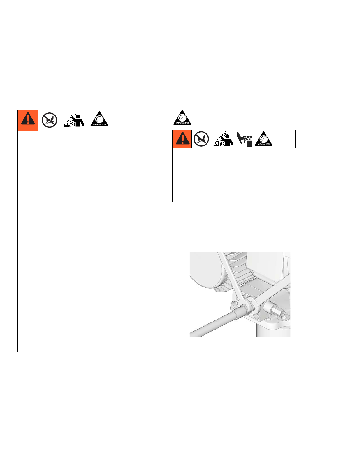
Pressure Relief
Follow the Pressure Relief Procedure whenever
you see this symbol.
This equipment stays pressurized until pressure is
manually relieved. To help prevent serious injury
from pressurized fluid, such as skin injection,
splashing fluid and moving parts, follow the Pressure
Relief Procedure when you stop dispensing and
before cleaning, checking, or servicing the
equipment.
To relieve pressure in the system, use two wrenches
working in opposite directions on pump outlet fitting to
slowly loosen fitting only until fitting is loose and no
more lubricant or air is leaking from fitting as shown in
F
IG. 1.
PRESSURIZED ALUMINUM PARTS HAZARD
Use of fluids that are incompatible with aluminum in
pressurized equipment can cause serious chemical
reaction and equipment rupture. Failure to follow this
warning can result in death, serious injury, or property
damage.
• Do not use 1,1,1-trichloroethane, methylene chloride, other halogenated hydrocarbon solvents or
fluids containing such solvents.
• Many other fluids may contain chemicals that can
react with aluminum. Contact your material supplier
for compatibility.
FIG. 1
2 332519F
Page 3

Instructions
a
b
a
c
8
Vent Valve Installation
Reference numbers used in these instructions correspond to Parts included in Kit and are provided on page
5. Parts identified with an alpha character are user provided or already installed components.
To ensure the correct pressure relief valve is used and
pressure settings are correct, always use new parts
included in your Vent Valve Kit for reassembly.
1. If unit has already been in service, relieve pressure
(see Pressure Relief procedure, page 2).
2. Disconnect Dyna-Star HP or HF pump from main
power source.
3. Remove outlet tubing from port marked “0” on the
pump adapter block (a) (F
IG. 2).
5. Loosen, remove and discard the 3 socket head cap
screws (b) from the adapter block (a) (F
IG. 3).
FIG. 3
6. Remove adapter block (a) and o-rings (c) (F
IG. 3).
Discard these parts according to state and local
codes for proper disposal. These parts will not be
used for reassembly.
7. Grease o-rings (8) and install o-rings in vent valve
block as shown in F
IG. 4.
FIG. 4
FIG. 2
4. Remove plug or inlet tubing from port marked “1” on
the pump adapter block (a) (F
IG. 2).
Clean surface of the Dyna-Star pump outlet with a
clean dry cloth. Inspect pump surface for scratches or
nicks. A scratched surface can result in fluid leakage.
332519F 3
Page 4

Instructions
4
1
10
d
c
8. Install vent valve (1) to pump surface using the 3
cap screws (4) included in the kit (F
IG. 5). Hold the
vent valve tight to the surface of the pump to ensure
o-rings stay in place during installation.Torque
screws to 17-19 ft-lbs (23-26 N.m).
FIG. 5
9. Install lubrication line to vent valve pump outlet port
marked “0” (F
IG. 6).
11. Connect cable (d) to valve cartridge (c) (F
IG. 7).
FIG. 7
12. Install other end of cable (d) to solenoid control
device.
NOTE:
• Cable (d) is available from Graco. See Accesso-
ries, page 5 for a list of available cables.
• Connector termination is a Deutsch DT-04-2P.
• Solenoid inputs are not polarity dependent.
Voltage can be applied in either direction.
FIG. 6
10. In the inlet port marked “1” (F
IG. 6) install either:
• a plug (10).
• inlet plumbing necessary to attach a fill pump.
NOTE:
• For tube-in-tube pump models, the “1” inlet can
be used as a fill port.
• For models equipped with a follower plate, without a tube-in-tube, the “1” inlet deposits grease
on top of the follower plate.
• Solenoid should be activated when the pump is
running. See wiring diagrams in pump manual
for more details.
13. Reconnect pump to main power supply.
14. Test system to ensure proper operation.
4 332519F
Page 5

Parts
1
2
8
4
3
9
10
Ref Description Qty
1 MANIFOLD, electric vent valve 1
2 VALVE, cartridge, 24VDC 1
3 VALVE, pressure relief, 3500 psi 1
4 SCREW, cap, socket, M8 x 1.25 3
8O-RING 2
9 PLUG, pipe, 1/8 in. npt 1
10 PLUG, 1/4 in. npt 1
Accessories
Part No. Description
24N402 CABLE, 6 ft, vent valve, 2 pin for vent valve
control
77X529 CABLE, power injector system only. Use
with 77X528
77X528 CABLE, power extension, 15 ft (4.6m), use
with 77X529
Parts
Technical Data
.
Vent Valve for Dyna-Star HP
US Metric
Maximum working pressure* 3500 psi 24.1 MPa, 241 bar
Inlet/Outlet Sizes
Outlet (marked “0”)
Inlet (refill - marked “1”)
Pressure Relief Valve
Factory Set Pressure 4000 psi +
Reset Pressure 80% of set pressure
Relief Rate** 0.1 gallons/minute @3500 psi 0.4 liters/minute @24.1 MPa. 241 bar
Solenoid Valve
Flow** Up to gpm 0.2 gallons/minute,
Wetted materials Zinc plated steel, carbon steel, aluminum, fluoroelastomer, polyurethane
Weight 4.0 lbs 1.8 kg
IP Rating IP65K
Solenoid Coil Resistance (DC) (Ohms) @ 68°F (20°C) Initial Current Draw (Amps)
24 VDC 28.8 0.83
40 in
250 psi 27 MPa, 275 bar + 10%
3
/minute
*Dyna-Star HP Pump Models are rated for 5000 psi (34.47 MPa, 344 bar) maximum working pressure, however,
when a vent valve is installed on the HP Pump, the maximum working pressure must be reduced to 3500 psi (24.1
MPa, 241 bar).
3/8 in. npt(f)
3/8 in. npt(f)
0.65 liters/minute
**Flow capability depends on viscosity, type of fluid, temperature, etc.
332519F 5
Page 6

Dimensions
4.95 in.
2.5 in.
1.5 in.
4.0 in.
1.5 in (3.81 cm)
(12.57 cm)
(6.36 cm)
(3.81 cm)
(10.16 cm)
Graco Information
For the latest information about Graco products, visit www.graco.com.
TO PLACE AN ORDER, contact your Graco distributor or call to identify the nearest distributor.
Phone: 612-623-6928 or Toll Free: 1-800-533-9655, Fax: 612-378-3590
All written and visual data contained in this document reflects the latest product information available at the time of publication.
GRACO INC. AND SUBSIDIARIES • P.O. BOX 1441 • MINNEAPOLIS MN 55440-1441 • USA
Copyright 2013, Graco Inc. All Graco manufacturing locations are registered to ISO 9001.
Graco reserves the right to make changes at any time without notice.
For patent information, see www.graco.com/patents.
Original instructions. This manual contains English. MM 332519
Graco Headquarters: Minneapolis
International Offices: Belgium, China, Japan, Korea
www.graco.com
August 2014
 Loading...