

Page 1
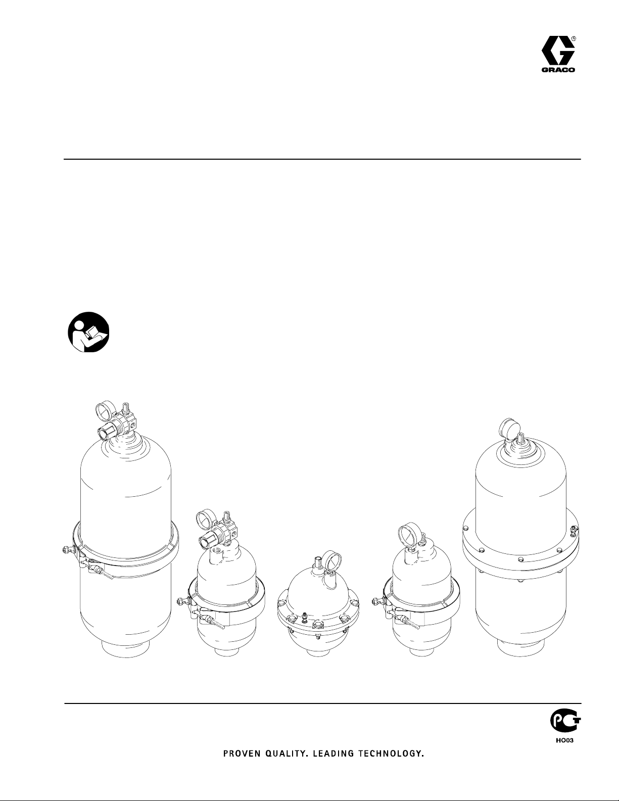
Instructions–Parts List
Huskyt750 and Huskyt2000
Surge Suppressors
For control of pressure fluctuations and acceleration loss,
preventing cavitation. For professional use only.
120 psi (0.8 MPa, 8 bar) Maximum Air Input Pressure
120 psi (0.8 MPa, 8 bar) Maximum Fluid Working Pressure
See the Model Numbers on page 12.
Important Safety Instructions
Read all warnings and instructions in this manual.
Save these instructions.
308703G
ENG
06887
Model 239088 Model 239096Model 239095 Model 239126Model 239091
06891
06888
06892
06894
Page 2
Table of Contents
Symbols
Symbols 2. . . . . . . . . . . . . . . . . . . . . . . . . . . . . . . . . . . . . .
Warnings 2. . . . . . . . . . . . . . . . . . . . . . . . . . . . . . . . . . . . . .
Installation 4. . . . . . . . . . . . . . . . . . . . . . . . . . . . . . . . . . . . .
Operation 7. . . . . . . . . . . . . . . . . . . . . . . . . . . . . . . . . . . . .
Troubleshooting 9. . . . . . . . . . . . . . . . . . . . . . . . . . . . . . . .
Service 10. . . . . . . . . . . . . . . . . . . . . . . . . . . . . . . . . . . . . .
Model Numbers 12. . . . . . . . . . . . . . . . . . . . . . . . . . . . . . .
Parts Matrix 13. . . . . . . . . . . . . . . . . . . . . . . . . . . . . . . . . .
Parts Drawings 14. . . . . . . . . . . . . . . . . . . . . . . . . . . . . . . .
Dimensions 16. . . . . . . . . . . . . . . . . . . . . . . . . . . . . . . . . . .
Technical Data 17. . . . . . . . . . . . . . . . . . . . . . . . . . . . . . . .
Graco Standard Warranty 18. . . . . . . . . . . . . . . . . . . . . .
Graco Information 18. . . . . . . . . . . . . . . . . . . . . . . . . . . . .
WARNING
EQUIPMENT MISUSE HAZARD
Equipment misuse can cause the equipment to rupture or malfunction and result in serious injury.
INSTRUCTIONS
D This equipment is for professional use only.
D Read all instruction manuals, tags, and labels before operating the equipment.
Warning Symbol
WARNING
This symbol alerts you to the possibility of serious
injury or death if you do not follow the instructions.
Caution Symbol
CAUTION
This symbol alerts you to the possibility of damage to
or destruction of equipment if you do not follow the
instructions.
D Use the equipment only for its intended purpose. If you are not sure, call your Graco distributor.
D Do not alter or modify this equipment. Use only genuine Graco parts and accessories.
D Check equipment daily. Repair or replace worn or damaged parts immediately.
D Do not exceed the maximum working pressure of the lowest rated component in your system. This
equipment has a 120 psi (0.8 MPa, 8 bar) maximum working pressure and 120 psi (0.8 MPa,
8 bar) maximum incoming air pressure.
D Solvent Compatibility:
– Use fluids and solvents which are compatible with the equipment wetted parts.
– Use only compatible solvents to clean all plastic parts. Many solvents can degrade plastic
parts to the point where they could fail.
Refer to the Technical Data section of all equipment manuals. Read the fluid and solvent
manufacturer’s warnings.
D Do not use hoses to pull equipment.
D Do not lift pressurized equipment.
D Comply with all applicable local, state, and national fire, electrical, and safety regulations.
D Do not operate outside the minimum and maximum operating temperature of your surge
suppressor unit. See Minimum and Maximum Operating Temperatures on page 7.
2 308703
Page 3
WARNING
TOXIC FLUID HAZARD
Hazardous fluid or toxic fumes can cause serious injury or death if splashed in the eyes or on the skin,
inhaled, or swallowed.
D Know the specific hazards of the fluid you are using.
D Store hazardous fluid in an approved container. Dispose of hazardous fluid according to all local,
state and national guidelines.
D Always wear protective eyewear, gloves, clothing and respirator as recommended by the fluid and
solvent manufacturer.
D Pipe and dispose of the exhaust air safely, away from people, animals, and food handling areas. If
the diaphragm fails, the fluid is exhausted along with the air.
D Never use an acetal pump to pump acids. Take precautions to avoid acid or acid fumes from
contacting the pump housing exterior. Stainless steel parts will be damaged by exposure to acid
spills and fumes.
FIRE AND EXPLOSION HAZARD
Improper grounding, poor ventilation, open flames or sparks can cause a hazardous condition and
result in a fire or explosion and serious injury.
D Charge the surge suppressor with compressed air or nitrogen only. Do not use oxygen. Such
use could result in an explosion.
D Never pump flammable fluids with polypropylene units.
D Ground the equipment. Refer to Grounding on pages 4 and 5.
D Never use a polypropylene pump or surge suppressor with non-conductive flammable fluids as
specified by your local fire protection code. Refer to Grounding on pages 4 and 5 for additional
information. Consult your fluid supplier to determine the conductivity or resistivity of your fluid.
D If there is any static sparking or you feel an electric shock while using this equipment, stop pump-
ing immediately. Do not use the equipment until you identify and correct the problem.
D Provide fresh air ventilation to avoid the buildup of flammable fumes from solvents or the fluid
being pumped.
D Pipe and dispose of the exhaust air safely, away from all sources of ignition.
D Keep the work area free of debris, including solvent, rags, and gasoline.
D Electrically disconnect all equipment in the work area.
D Extinguish all open flames or pilot lights in the work area.
D Do not smoke in the work area.
D Do not turn on or off any light switch in the work area while operating or if fumes are present.
D Do not operate a gasoline engine in the work area.
308703 3
Page 4
Installation
Grounding
WARNING
FIRE AND EXPLOSION HAZARD
When pumping flammable fluids, the
surge suppressor must be grounded.
Before pumping, ground the system as
explained below. Also read the section
FIRE OR EXPLOSION HAZARD on
page 3.
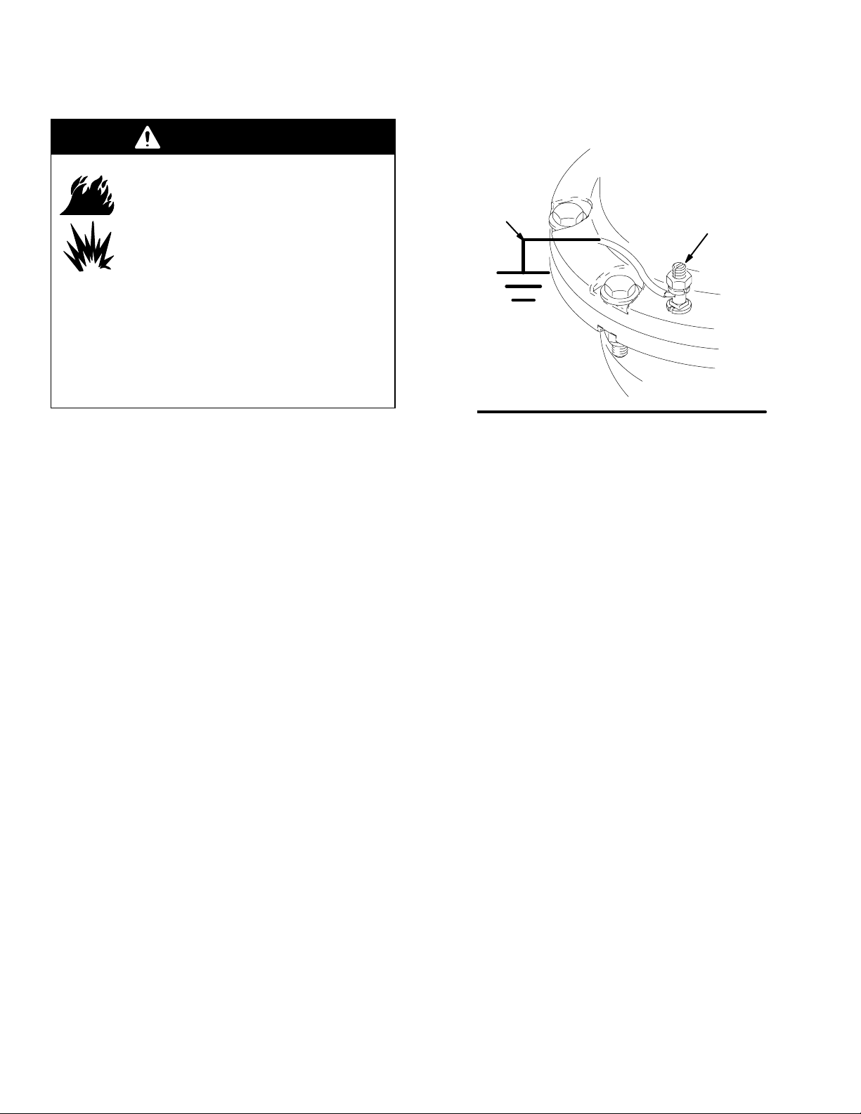
Polypropylene surge suppressors are not
conductive. Attaching the ground wire to the
grounding lug grounds only the clamp or flange
(see Fig. 1). When pumping conductive flammable
fluids, always ground the entire fluid system by
making sure the fluid has an electrical path to a
true-earth ground.
To reduce the risk of static sparking, ground the surge
suppressor and all other equipment in the pumping
area. Check your local electrical code for detailed
grounding instructions for your area and type of equipment. Ground all of this equipment:
D Surge suppressor: Attach a ground wire to the
grounding lug (2) as shown in Fig. 1. Connect the
clamp end of the ground wire to a true earth
ground. To order a ground wire and clamp, order
Part No. 222011.
NOTE: To connect the ground wire to the surge
suppressor, first remove the copper connector from
the non-clamp end of the ground wire and discard
it, then push the bare wire through the grounding
lug on the surge suppressor.
D Fluid supply container: Follow your local code.
23
Fig. 1
NOTE: When pumping conductive flammable fluids
with a surge suppressor, always ground the entire
fluid system. See the WARNING at left. Fig. 2
shows recommended methods of grounding fluid
containers during filling. These are only guides;
contact your Graco distributor for assistance in
grounding your system.
D Air compressor: Follow the manufacturer’s
recommendations.
D Solvent pails used when flushing: Follow your local
code. Use only grounded metal pails, which are
conductive. Do not place the pail on a
non-conductive surface, such as paper or
cardboard, which interrupts the grounding
continuity.
2
4 308703
Page 5
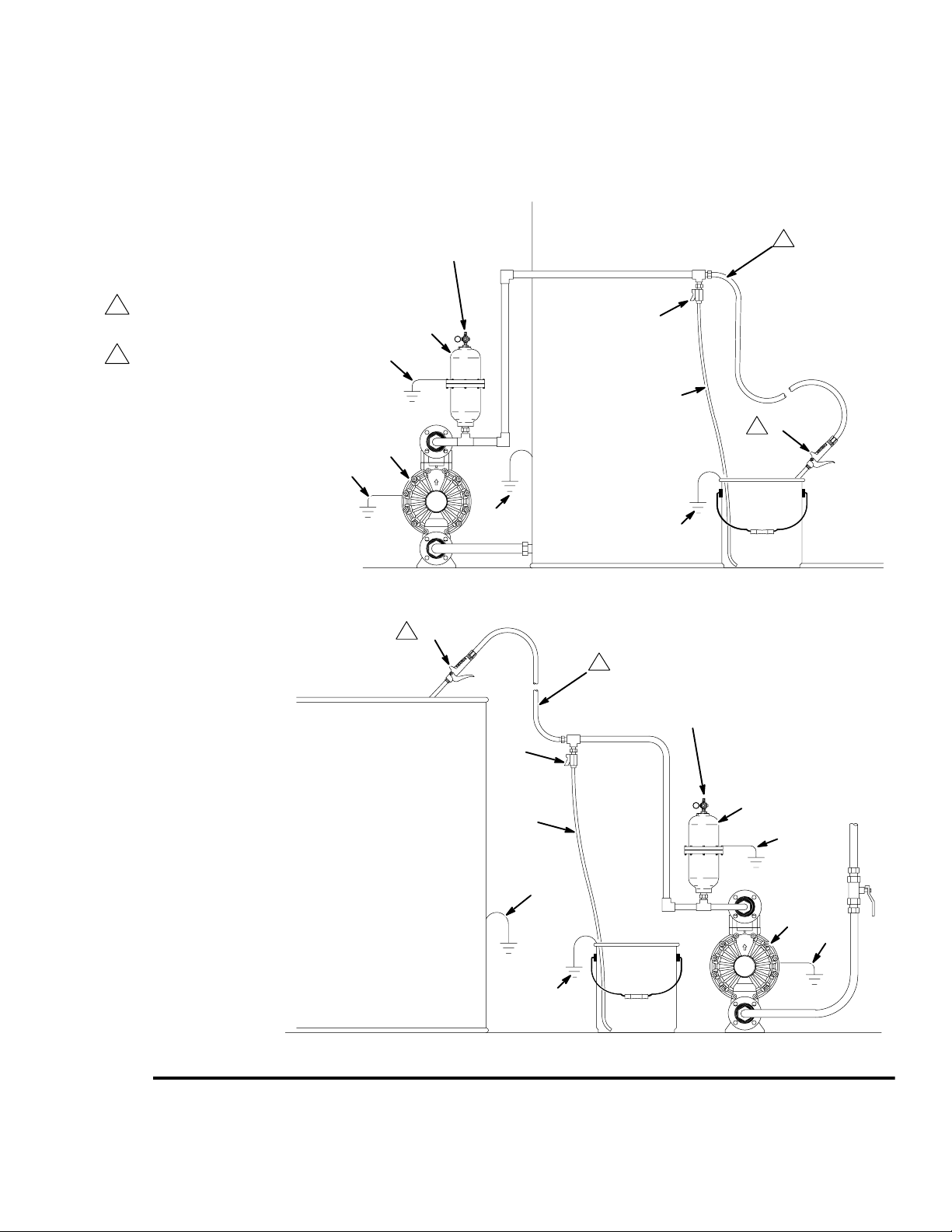
Grounding a Surge Suppressor
A Husky pump
B Husky surge suppressor
H Fluid drain valve (required)
S Dispense valve
T Fluid drain line
W Surge suppressor ground wire (required)
See page 4 for installation instructions.
Y Air motor ground wire (required)
Z Container ground wire (required)
Hose must be conductive.
1
Dispense valve nozzle must be in
2
contact with the container.
Y
Installation
air supply
connection
B
W
A
1
H
T
2
S
Z
Z
06895
2
S
1
air supply
connection
H
B
T
W
Z
A
Y
Fig. 2
Z
06896A
308703 5
Page 6

Installation
The installations in Fig. 2 are guides for selecting and installing system components. Contact your Graco distributor
for assistance in planning a system to suit your needs.
Mounting Automatic and Manual Models
Be sure the mounting surface can support the weight of the pump, surge suppressor, hoses, and accessories, and
the stress caused during operation.
D Mount the surge suppressor as close to the pump discharge as possible and upstream of equipment such as
valves, meters, filters, and so on. The surge suppressor should be installed within 10 pipe diameters of the
pump discharge.
D If you use a flexible connector from the pump to the piping system, the surge suppressor should be mounted to
the pump discharge manifold, and the flexible connector should be attached to the surge suppressor tee and
system piping.
D Because pressure is equal in all directions, the surge suppressor can be installed in any position, but the vertical
position shown in Fig. 2 is recommended for better draining. Fluids with high specific gravity or high viscosity,
settling of heavy material, and possible air entrapment further limit the mounting positions other than those
shown in Fig. 2.
NOTE: When you mount a plastic surge suppressor, do not overtighten by using a large pipe wrench near the
threads of the fluid inlet. The housing may crack if tightened too much. Hand tightening is recommended.
Connecting Automatic Models
D Connect the 1/4-in air supply hose to the 1/4 npt
connection on the top of the surge suppressor.
D The air pressure to the surge suppressor must be
greater than or equal to the pump discharge and/or
system pressure. For equal air pressure, you can
use a tee in the pump’s air supply line to run an air
line to the surge suppressor.
D For models with elastomer bladders, the tee must
be located in the pump’s air supply line before any
pump controller or instrumentation such as the
filter, regulator, or pump control valve.
D For models with PTFE bellows, the tee must be
located in the pump’s air supply line after any pump
controller or instrumentation such as the filter,
regulator, or pump control valve.
Connecting Manual Models
D Connect the 1/4-in air supply hose to the brass
one-way check valve on the top of the surge suppressor.
D The air pressure to the surge suppressor must be
greater than or equal to the pump discharge and/or
system pressure. For equal air pressure, you can
use a tee in the pump’s air supply line to run an air
line to the surge suppressor.
D The tee must be located in the pump’s air supply
line before any pump controller or instrumentation
such as the filter, regulator, or pump control valve.
6 308703
Page 7

Operation
Pressure Relief Procedure
WARNING
PRESSURIZED EQUIPMENT HAZARD
The equipment stays pressurized until pressure is
manually relieved. To reduce the risk of serious
injury from pressurized fluid, accidental spray from
the dispensing device, or splashing fluid, follow this
procedure whenever you
D Are instructed to relieve pressure
D Stop pumping
D Check, clean, or service any system equipment
D Install or clean fluid nozzles
1. Stop pumping, and shut off the air to the pump.
2. Relieve pressure in the surge suppressor as
follows:
D For automatic surge suppressors, remove the
air pressure gauge, and allow any residual air
pressure to escape.
D For manual surge suppressors, adjust the
regulator to relieve the air pressure by dialing
down the pressure.
Minimum and Maximum Operating
Temperatures
Find the minimum and maximum operating temperatures for your surge suppressor unit in the list below.
These temperature limits are stated at zero gauge
pressure.
Automatic Husky 750
239095 10_ to 180_ F (–12_ to 82_ C)
239096 32_ to 175_ F (0_ to 79_ C)
239121 40_ to 175_ F (4_ to 79_ C)
239122 32_ to 175_ F (0_ to 79_ C)
239123 40_ to 220_ F (4_ to 104_ C)
239124 –10_ to 350_ F (–23_ to 176_ C)
Automatic Husky 2000
WARNING
TOXIC FLUID HAZARD
Hazardous fluid or toxic fumes can
cause serious injury or death if splashed
in the eyes or on the skin, inhaled, or
swallowed.
D Read TOXIC FLUID HAZARD on page 3.
D Use fluids and solvents which are compatible
with the equipment wetted parts. Refer to the
Technical Data section of all equipment manuals. Read the fluid and solvent manufacturer’s
warnings.
WARNING
FIRE AND EXPLOSION HAZARD
Charge the surge suppressor with
compressed air or nitrogen only. Do not
use oxygen.
Never pump flammable fluids with
polypropylene units.
Charging the surge suppressor with oxygen or
pumping flammable fluids with polypropylene units
could cause a fire or an explosion.
239092 32_ to 175_ F (0_ to 79_ C)
239093 32_ to 175_ F (0_ to 79_ C)
239126 40_ to 175_ F (4_ to 79_ C)
239127 32_ to 175_ F (0_ to 79_ C)
239128 40_ to 175_ F (4_ to 79_ C)
Manual Husky 750
239090 10_ to 180_ F (–12_ to 82_ C)
239091 32_ to 175_ F (0_ to 79_ C)
239129 40_ to 175_ F (4_ to 79_ C)
239130 32_ to 175_ F (0_ to 79_ C)
239131 40_ to 220_ F (4_ to 104_ C)
239132 –10_ to 350_ F (–23_ to 176_ C)
Manual Husky 2000
239087 32_ to 175_ F (0_ to 79_ C)
239088 32_ to 175_ F (0_ to 79_ C)
239134 40_ to 175_ F (4_ to 79_ C)
239135 32_ to 175_ F (0_ to 79_ C)
239136 40_ to 175_ F (4_ to 79_ C)
308703 7
Page 8

Operation
Charging and Startup
For optimum performance, surge suppressors should be charged to a pressure 2 to 10 psi (0.01 to 0.07 MPa,
0.1 to 0.7 bar) lower than system pressure.
Automatic Models
CAUTION
Automatic surge suppressors must have the air
supply connected before you start pumping. Failure
to do so could result in the internal air valve
puncturing or rupturing the bladder.
The air pressure gauge (1) (See Parts Drawings on
pages 14 and 15) on automatic surge suppressors
remains at zero pressure even after the air line is
connected, because the surge suppressor only allows
air into the air chamber when it is required to dampen
pulsation. After the air supply line is attached to the
one-way check valve (8) and air is available, you can
start the pump. No further adjustments are necessary.
NOTE: Automatic surge suppressors are not recommended for use as suction stabilizers at the pump inlet
or as a surge suppressor at a quick-closing valve.
Adjustable surge suppressors should be used for such
applications.
Manual Models
CAUTION
Manual surge suppressors must be charged before
you start pumping. Failure to do so could result in
the internal air valve puncturing or rupturing the
bladder.
Before you start the pump, charge the surge suppressor with air line pressure.
1. Start the pump to generate system pressure.
2. As pressure increases to approach working pressure, gradually decrease the regulated air supply
pressure into the surge suppressor by adjusting
the regulator (4) (See Parts Drawings on pages
14 and 15).
3. Wait for up to one minute to allow the system to
respond to the adjustment before you make any
further adjustments. Generally, pulsation is most
effectively minimized when the air supply to the
surge suppressor is regulated to 2 to 10 psi (0.01
to 0.07 MPa, 0.1 to 0.7 bar) lower than system
pressure.
8 308703
Page 9
Troubleshooting
WARNING
To reduce the risk of serious injury whenever you
are instructed to relieve pressure, always follow the
Pressure Relief Procedure on page 7.
Relieve the pressure before checking or servicing the
equipment.
Check all possible problems and causes before disassembling the pump.
PROBLEM
Surge suppressor does not hold
pressure.
Dampening effect of surge
suppressor is not sufficient.
CAUSE SOLUTION
Manual or automatic models:
–Leaking threaded connections
–Loose flange bolts or clamp
–Failed bladder or bellows
–Blocked air line to unit
Automatic models only:
–One-way valve at air inlet is
installed backwards.
–Gauge shows no pressure,
and pump is not running.
Manual models only:
–Faulty regulator –Check regulator.
Surge suppressor installed incorrect
distance from pump
Improper pressure charge See Charging and Startup,
Surge suppressor does not hold
pressure charge.
Failed bladder or bellows See Bladder Failure, page 10.
–Check all threads for leaks.
–See Torque Table, page 11.
–See Bladder Failure, page 10.
–Use 1/4-in air line.
–Arrow should point toward surge
suppressor.
–Pressure does not register on
gauge until pump is started.
Surge suppressor should be
installed within 10 pipe diameters of
pump discharge.
page 8. Surge suppressor
pressure should be 2 to 10 psi (0.01
to 0.07 MPa, 0.1 to 0.7 bar) lower
than system pressure.
See surge suppressor does not hold
pressure in PROBLEM column.
There is leaking around surge
suppressor fluid inlet.
Surge suppressor too small for
pump
Automatic models only:
Plugged automatic valve
PTFE sealing tape or paste is
needed on threads of fluid inlet.
Install larger surge suppressor.
Remove pressure from surge
suppressor, and check automatic
valve for proper operation as
follows:
1. Leave air line attached to top
half of surge suppressor.
2. Fill top of surge suppressor
with enough water to cover
automatic valve.
There should be no bubbles.
3. Dump water out, and gently
push automatic valve.
Air should flow.
4. Replace automatic valve if
it is defective.
Apply PTFE tape or paste to
threads. Do not overtighten plastic
models. Hand tightening is
recommended.
308703 9
Page 10

Service
Bladder Failure
Normal life for bladders can be from a few months to
several years, depending upon the harshness of the
application. Below are common reasons for failed
bladders or bellows:
D Chemical attack: Check chemical compatibility
charts. Consult your Graco distributor.
D Cut bladder or bellows: Check for sharp objects
that may have been introduced into the surge
suppressor through pumped fluid.
D Insufficient compressed air charge in surge sup-
pressor during operation: See Charging and
Startup on page 8.
D Surge suppressor too small for the pump: An
undersized surge suppressor will have premature
bladder failure. Contact your Graco distributor for
assistance in ensuring that you have the correct
size surge suppressor.
Replacing Bladder or Bellows
1. Relieve the pressure.
WARNING
To reduce the risk of serious injury whenever you
are instructed to relieve pressure, always follow the
Pressure Relief Procedure on page 7.
2. Remove the clamp band, ring flange, or bolts.
3. Remove the top housing of the surge suppressor.
4. Remove the old bladder or bellows, and replace it
with the new bladder or bellows.
Make sure that you properly orient the parts:
D Install rubber bladders with the concave side
facing the top housing, as shown in the Parts
Drawings on page 14.
D Install PTFE bellows with the concave side
facing the bottom housing, as shown in Model
No. 239126 in the Parts Drawings on
page 15. Install the PTFE encapsulated fluoroelastomer o-rings on each side of the bellows.
5. Replace the top housing of the surge suppressor.
6. Replace the clamp band, ring flange, or bolts, and
torque according to the torque specifications in the
Torque Table on page 11.
10 308703
Page 11

Service
Torque Table
Find the proper torque specifications for your surge suppressor unit in the table below. These are the torques to
which the clamp band, ring flange, or bolts in bolted units need to be tightened.
KEY: plastic = polypropylene or acetal
metal = stainless steel
rubber = fluoroelastomer or Buna–N
Bladder
Model
Husky 2000 rubber plastic clamp band 45 to 55 in-lb (5.1 to 6.2 N-m)
Husky 2000 rubber plastic ring flange 65 to 70 in-lb (7.3 to 7.9 N-m)
Husky 2000 PTFE plastic ring flange 90 to 105 in-lb (10.2 to 11.9 N-m)
Husky 2000 rubber metal and plastic clamp band 30 to 40 in-lb (3.4 to 4.5 N-m)
Husky 2000 rubber metal and plastic ring flange 80 to 85 in-lb (9.0 to 9.6 N-m)
Husky 2000 PTFE metal and plastic ring flange 90 to 95 in-lb (10.2 to10.7 N-m)
Husky 2000 rubber metal bolted unit 120 to 130 in-lb (13.6 to 14.7 N-m)
Husky 2000 PTFE metal bolted unit 145 to 150 in-lb (16.4 to 16.9 N-m)
Husky 750 rubber plastic clamp band 40 to 45 in-lb (4.5 to 5.1 N-m)
Husky 750 rubber plastic ring flange 50 to 55 in-lb (5.6 to 6.2 N-m)
Husky 750 PTFE plastic clamp band 80 to 85 in-lb (6.8 to 9.6 N-m)
Husky 750 PTFE plastic ring flange 85 to 90 in-lb (9.6 to 10.2 N-m)
Husky 750 rubber metal bolted unit 80 to 85 in-lb (9.0 to 9.6 N-m)
Husky 750 PTFE metal bolted unit 110 to 115 in-lb (12.4 to 13.0 N-m)
Material
Housing
Material
Type of Clamp Torque
308703 11
Page 12

Model Numbers
Automatic Husky 750, 3/4-in Surge Suppressors
Polypropylene Wetted Bottom Housing and Non-Wetted Top Housing
239096 with Buna–N bladder
239121 with PTFE bellows
239122 with fluoroelastomer bladder
Stainless Steel Wetted Bottom Housing and Non-Wetted Top Housing
239095 with Buna–N bladder
239123 with PTFE bellows
239124 with fluoroelastomer bladder
Automatic Husky 2000, 2-in Surge Suppressors
Stainless Steel Wetted Bottom Housing, Polypropylene Non-Wetted Top Housing
239093 with Buna–N bladder
239126 with PTFE bellows
239127 with fluoroelastomer bladder
Polypropylene Wetted Bottom Housing and Non-Wetted Top Housing
239092 with Buna–N bladder
239128 with PTFE bellows
Manual Husky 750, 3/4-in Surge Suppressors
Polypropylene Wetted Bottom Housing and Non-Wetted Top Housing
239091 with Buna–N bladder
239129 with PTFE bellows
239130 with fluoroelastomer bladder
Stainless Steel Wetted Bottom Housing and Non-Wetted Top Housing
239090 with Buna–N bladder
239131 with PTFE bellows
239132 with fluoroelastomer bladder
Manual Husky 2000, 2-in Surge Suppressors
Stainless Steel Wetted Bottom Housing, Polypropylene Non-Wetted Top Housing
239088 with Buna–N bladder
239134 with PTFE bellows
239135 with fluoroelastomer bladder
Polypropylene Wetted Bottom Housing and Non-Wetted Top Housing
239087 with Buna–N bladder
239136 with PTFE bellows
12 308703
Page 13

Parts Matrix
is 1 for every model
The X’s indicate the
Replacement Parts for Huskyt 750 and Huskyt 2000 Surge Suppressors, Series A
Parts
Automatic
NOTE: The quantity of every part in this list
.
parts that are included in each model.
Ref
No. Part No. Description
1 100960 GAUGE, air press.;200 psi
(1.4 MPa, 14 bar); 1/4 npt
2 104029 LUG, grounding X X X X X X X X X X X X X X X X X X X X X X
3 104582 WASHER, tab X X X X X X X X X X X X X X X X X X X X X X
4 110318 REGULATOR, air; 1/4 npt X X X X X X X X X X X
5 110319 GAUGE, air press., 200 psi
(1.4 MPa, 14 bar); 1/8 npt
6 113872 CLAMP, band; SST X X X X X X
7 113878 BELLOWS, PTFE with
o-ring kit
8 113879 VALVE, check X X X X X X X X X X X X X X X X X X
9 113880 CLAMP, band; SST X X X X
’
Husky 750
2
2
2
2
3
3
3
3
9
9
9
0
9
5
X X X X X X X X X X X
9
0
1
1
9
2
2
6
1
2
Surge Suppressor Models
Automatic
Husky 2000
2
2
2
2
2
2
2
2
3
3
3
3
3
3
3
3
9
9
9
9
9
9
9
1
1
0
0
1
1
2
2
9
9
2
3
4
2
2
3
6
7
X X X X
9
1
0
2
9
8
0
X X X X X X X X X X X
Manual
Husky 750
2
2
2
3
3
3
9
9
9
0
1
1
9
2
3
1
9
0
Manual
Husky 2000
2
2
2
2
2
2
3
3
3
3
3
3
9
9
9
9
9
1
1
0
3
3
1
8
2
7
9
0
1
1
8
3
3
8
4
5
2
3
9
1
3
6
10 113881 FLANGE, ring, with fasteners X X X X
11 113882 VALVE ASSY, automatic
for rubber bladders
13 113884 FLANGE, ring, with fasteners X X
14 113885 BLADDER, Buna–N X X X X
15 113886 BELLOWS; PTFE with
o-ring kit
16 113887 VALVE ASSY, automatic
for rubber bladders
18 113889 BLADDER; fluoroelastomer X X
19 113890 BLADDER; fluoroelastomer X X X X
20 113891 BLADDER, Buna–N X X X X
21 113923 BOLT, WASHER, NUT SET X X X X X X
22 186620 STICKER, grounding symbol X X X X X X X X X X X X X X X X X X X X X X
24 290306 LABEL, identification X X X X X X X X X X X X X X X X X X X X X X
25 290322 LABEL, warning X X X X X X X X X X X X X X X X X X X X X X
26 290323 LABEL, product X X X X X X X X X X X X
27 290324 LABEL, product X X X X X X X X X X
28 290384 LABEL, caution X X X X X X X X X X X X X X X X X X X X X X
X X X X
X X X X X X
X X X X X
Non-Replacement Parts for Huskyt 750 and Huskyt 2000 Surge Suppressors, Series A
A Top housing (See Model Numbers list on page 12 for housing material of each model)
B Bottom housing (See Model Numbers list on page 12 for housing material of each model)
C Close nipple, SST; 1/4”
308703 13
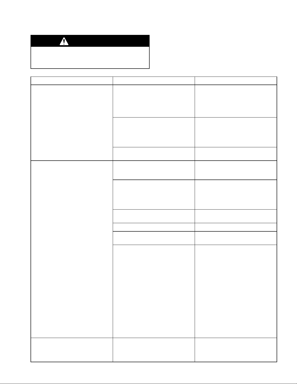
Page 14
Parts Drawings
(see Parts Matrix on page 13)
8
4
5
24, 25, 26, 28
hanging on regulator
C
A
8
4
21
22
5
2
3
24, 25, 26, 28
hanging on regulator
C
A
20
22
2
3
9
20
B
14 308703
06890
Model 239090
B
06889
Model 239091
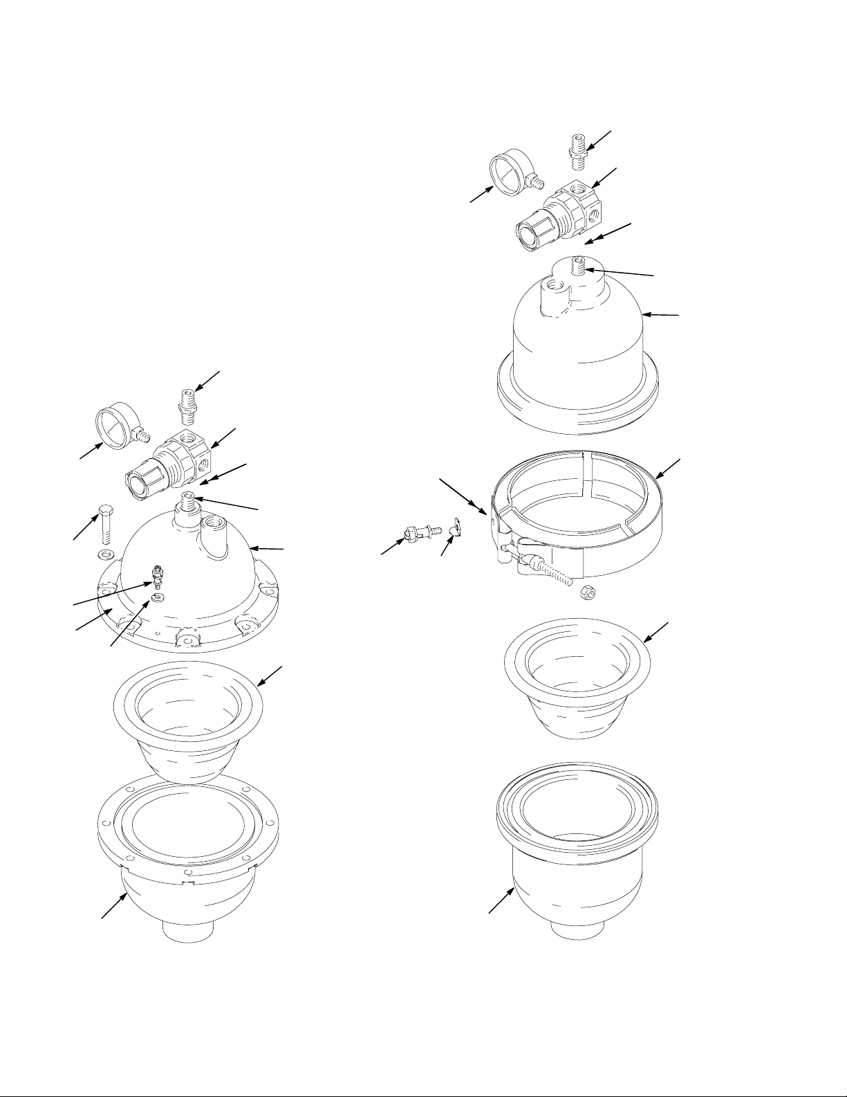
Page 15
Parts Drawings
(see Parts Matrix on page 13)
24, 25, 27, 28
hanging on regulator
22
2
3
C
8
4
10
5
C
A
6
includes fasteners
1
24, 25, 27, 28
hanging on gauge
2
3
22
A
11
7
14
B
10
B
06886
includes fasteners
Model 239088 Model 239126
06893
308703 15
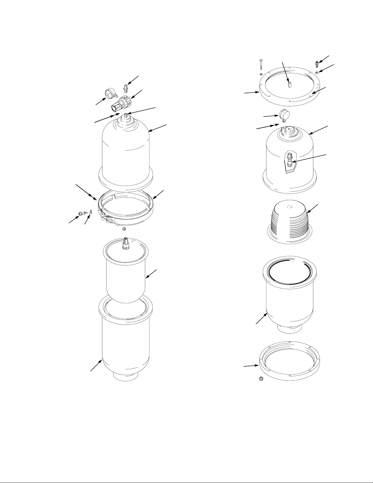
Page 16

Dimensions
Manual Husky 2000
8.5 in.
(216 mm)
239088 shown
06887
20.25 in.
(514 mm)
23.25 in.
(591 mm)
8.5 in.
(216 mm)
2 npt fluid inlet
Automatic Husky 2000
239126 shown
22.50 in.
(572 mm)
20.25 in.
(514 mm)
06894
2 npt fluid inlet
Manual Husky 750
6.0 in.
(152 mm)
3/4 npt fluid inlet
239091 shown
10.0 in.
(254 mm)
06891
13.25 in.
(337 mm)
Automatic Husky 750
6.0 in.
(152 mm)
3/4 npt fluid inlet
239096 shown
12.5 in.
(318 mm)
10.0 in.
(254 mm)
06892
16 308703
Page 17

Technical Data
Maximum air input pressure 120 psi (0.8 MPa, 8 bar). . . . . . . . . . . . . . . . . . . . . . . . . . . . . . . . . . . . . . . . . . . . . . . . . . . .
Air line connection 1/4 npt. . . . . . . . . . . . . . . . . . . . . . . . . . . . . . . . . . . . . . . . . . . . . . . . . . . . . . . . . . . . . . . . . . . . . . . . . . . . . .
Fluid Inlet size
Husky 2000 models 2 npt. . . . . . . . . . . . . . . . . . . . . . . . . . . . . . . . . . . . . . . . . . . . . . . . . . . . . . . . . . . . . . . . . . . . . . . . . . . .
Husky 750 models 3/4 npt. . . . . . . . . . . . . . . . . . . . . . . . . . . . . . . . . . . . . . . . . . . . . . . . . . . . . . . . . . . . . . . . . . . . . . . . . . . .
Wetted and non-wetted parts See the Model Numbers list on page 12.. . . . . . . . . . . . . . . . . . . . . . . . . . . . . . . . . . . . . . .
Weight
Models 239091, 239096, 239121,
239122, 239129, and 239130 9 lb (4.1 kg). . . . . . . . . . . . . . . . . . . . . . . . . . . . . . . . . . . . . . . . . . . . . . . . . . . . . . . . . . . . . .
Models 239090, 239095, 239123, 239124, 239131, and 239132 16 lb (7.3 kg). . . . . . . . . . . . . . . . . . . . . . . . . . . . . . .
Models 239088, 239093, 239126, 239127, 239134, and 239135 36 lb (16.3 kg). . . . . . . . . . . . . . . . . . . . . . . . . . . . . .
Models 239087, 239092, 239128, and 239136 18 lb (8.2 kg). . . . . . . . . . . . . . . . . . . . . . . . . . . . . . . . . . . . . . . . . . . . . .
308703 17
Page 18

Graco Standard Warranty
Graco warrants all equipment manufactured by Graco and bearing its name to be free from defects in material and workmanship on the
date of sale by an authorized Graco distributor to the original purchaser for use. With the exception of any special, extended, or limited
warranty published by Graco, Graco will, for a period of twelve months from the date of sale, repair or replace any part of the equipment
determined by Graco to be defective. This warranty applies only when the equipment is installed, operated and maintained in accordance with Graco’s written recommendations.
This warranty does not cover, and Graco shall not be liable for general wear and tear, or any malfunction, damage or wear caused by
faulty installation, misapplication, abrasion, corrosion, inadequate or improper maintenance, negligence, accident, tampering, or substitution of non-Graco component parts. Nor shall Graco be liable for malfunction, damage or wear caused by the incompatibility of
Graco equipment with structures, accessories, equipment or materials not supplied by Graco, or the improper design, manufacture,
installation, operation or maintenance of structures, accessories, equipment or materials not supplied by Graco.
This warranty is conditioned upon the prepaid return of the equipment claimed to be defective to an authorized Graco distributor for
verification of the claimed defect. If the claimed defect is verified, Graco will repair or replace free of charge any defective parts. The
equipment will be returned to the original purchaser transportation prepaid. If inspection of the equipment does not disclose any defect
in material or workmanship, repairs will be made at a reasonable charge, which charges may include the costs of parts, labor, and
transportation.
THIS WARRANTY IS EXCLUSIVE, AND IS IN LIEU OF ANY OTHER WARRANTIES, EXPRESS OR IMPLIED, INCLUDING BUT
NOT LIMITED TO WARRANTY OF MERCHANTABILITY OR WARRANTY OF FITNESS FOR A PARTICULAR PURPOSE.
Graco’s sole obligation and buyer’s sole remedy for any breach of warranty shall be as set forth above. The buyer agrees that no other
remedy (including, but not limited to, incidental or consequential damages for lost profits, lost sales, injury to person or property, or any
other incidental or consequential loss) shall be available. Any action for breach of warranty must be brought within two (2) years of the
date of sale.
Graco makes no warranty, and disclaims all implied warranties of merchantability and fitness for a particular purpose in connection
with accessories, equipment, materials or components sold but not manufactured by Graco. These items sold, but not manufactured
by Graco (such as electric motors, switches, hose, etc.), are subject to the warranty, if any, of their manufacturer. Graco will provide
purchaser with reasonable assistance in making any claim for breach of these warranties.
In no event will Graco be liable for indirect, incidental, special or consequential damages resulting from Graco supplying equipment
hereunder, or the furnishing, performance, or use of any products or other goods sold hereto, whether due to a breach of contract,
breach of warranty, the negligence of Graco, or otherwise.
FOR GRACO CANADA CUSTOMERS
The parties acknowledge that they have required that the present document, as well as all documents, notices and legal proceedings
entered into, given or instituted pursuant hereto or relating directly or indirectly hereto, be drawn up in English. Les parties reconnaissent avoir convenu que la rédaction du présente document sera en Anglais, ainsi que tous documents, avis et procédures judiciaires
exécutés, donnés ou intentés à la suite de ou en rapport, directement ou indirectement, avec les procedures concernées.
Graco Information
For the latest information about Graco products, visit www.graco.com.
TO PLACE AN ORDER, contact your Graco distributor or call to identify the distributor closest to you:
Phone: 612–623–6921 or Toll Free: 1–800–328–0211 Fax: 612–378–3505
All written and visual data contained in this document reflects the latest product information available at the time of publication.
Graco reserves the right to make changes at any time without notice.
Original instructions. This manual contains English. MM 308703
18 308703
International Offices: Belgium, China, Japan, Korea
Graco Headquarters: Minneapolis
GRACO INC. P.O. BOX 1441 MINNEAPOLIS, MN 55440–1441
Copyright 1996, Graco Inc. is registered to ISO 9001
www.graco.com
Revised 06/2010
 Loading...