

Page 1
INSTRUCTIONS-PARTS
LIST
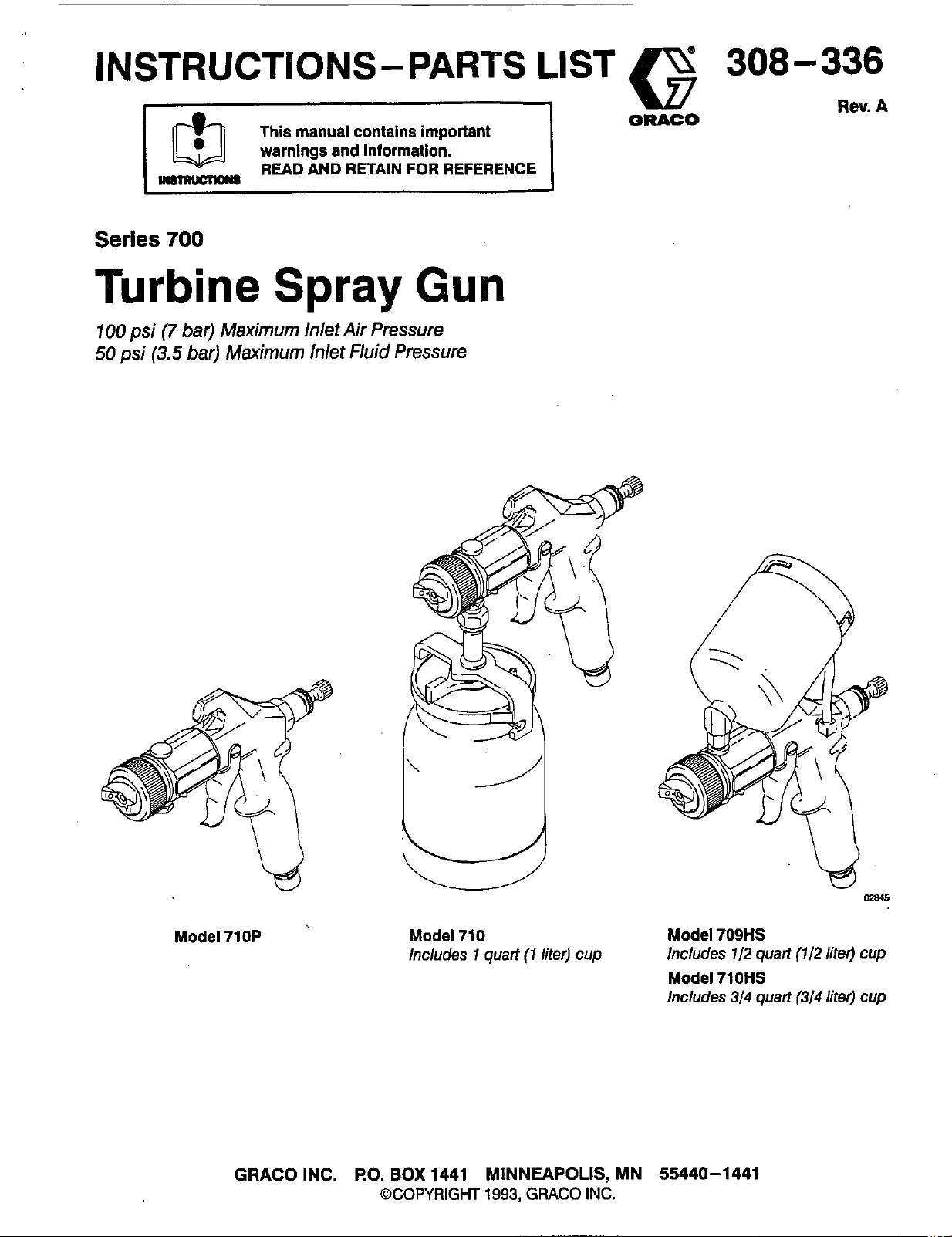
Series
700
Turbine
100
psi
(7
bar)
Maximum
50
psi
(3.5
bar)
Maximum
This manual contains important
warnings and information.
READ AND RETAIN FOR REFERENCE
Spray
Inlet Air Pressure
Inlet
Fluid
Gun
Pressure
G
ORACO
308-336
Rev.
A
Model 710P Model 710
GRACO INC.
lncludes 1 quart (1 liter) cup
RO.
BOX
1441 MINNEAPOLIS, MN 55440-1441
@COPYRIGHT
1993,
GRACO
ma(5
Model 709HS
Includes 112 quart (112 liter) cup
Model 710HS
lncludes 314 quart (314 liter) cup
INC.
Page 2
For
Professional Use Only. Observe
Read and understand all instruction manuals before operating equipment.
All
Warnings.
EQUIPMENT MISUSE
General Safety
Any misuse of the spray equipment or accessories,
such as improper usage, over pressurizing, modifying
parts, using incompatible chemicals and fluids, or
using worn or damaged parts, can
ture and result in serious injury, fire, explosion or
property damage.
Never point the spray gun at anyone or at any part
of the body.
Never put hand or fingers over the spray nozzle. Pressure Relief
0
Never try to stop or deflect leaks with Your hand or The spray gun cups and accessory remote pressure
body. pots remain pressurized until pressure is manually
Always turn
removing the spray gun cup.
0
Check all spray equipment regularly and repair or
replace worn or damaged parts immediately.
Only use genuine Graco replacement parts when remote pressure pot cover; and whenever you stop
servicing the gun. spraying.
off
the air supply to the gun before
cause
them to rup-
System Pressure
This gun has a
psi (7 bar) and a
Maximum
HaZARD
Marimum
Maximum
(3.5 bar).
exceed the maximum pressures of
pot, or any other component or accessory used in the
system.
relieved. To reduce the risk of serious injury from
pressurized fluid or accidental spray from the gun,
always relieve pressure in the cup or pressure pot
before checking or servicing any part of the spray
system; before installing, cleaning or changing fluid
nozzles: before loosening or removing the accessory
The
accessory remote pressure pots have a
hlet Air Pressure of
Met
Fluid
Pressure of
lnlet Air Pressure of
50
psi (3.5 bar). Never
the
gun, pressure
100
50
psi
Never alter
doing
Read and follow the fluid and solvent manufacturer’s literature regarding the use of protective
eyewear, gloves, clothing, respirator and other
equipment.
Fluid Compatibility
Be sure all fluids and solvents used are chemicallv
compatible with the “Welted Parts” shown in the
Technical Data on the back cover. Always read the
fluid and solvent manufacturer’s literature before
using the fluid or solvent in this gun.
Do
not use l,l,l-trichloroethane, methylene chloride,
other halogenated hydrocarbon solvents or fluids containing such solvents in the turbine spray system,
which contains aluminum and/or galvanized-coated
parts. Such use could result in a serious chemical
reaction, with the possibility of explosion, which could
cause death, serious injury, andlor substantial prop-
erty
damage.
or
modify any part of this equipment:
so
could cause it
to
malfunction.
Spray
Gun
Cup
To
relieve pressure:
off
1. Turn
2.
Unlatch the cup cover and loosen or remove the
cup from the cover.
Accessory
To
relieve pressure:
1.
Turn
2. 2 1/2
valve ring
relieved.
2
knob (113) about one turn. Wait until pressure
completely relieved before removing the cover.
Close the knob before using the system again.
See Fig.
the air supply to the gun.
Remote
off
the air supply to the pressure pot.
Gallon Remote Pot:
Quart Remote Pot: Turn
Pressure
(206c)
4
on page
Pot
Pull
until pressure
out
the pressure relief
7.
the pressure relief
is
completely
is
2
308-336
Page 3
Tighten all fluid connections securely before each use. Handle and route hoses carefully. Do not pull on
Do
Never
use
a damaged hose. Before each use, check
the entire hose for cuts, leaks, abrasion, bulging
cover. or damaae or movement of the hose CouDlinw.
If
anyof these conditions exist, replace the hose
immediately.
.-
hoses to move equipment.
vents which are not compatible with the inner tube
and cover of the hose.
not use fluids or
sol-
FIRE
.Sparking and Flammable
Sparking can be expected
the turbine motor. Sparks could ignite fumes from from plastic drop cloths, open flames such as pilot
flammable liquid, dust particles and other flammable lights, hot objects such
substances in the spray area, and cause serious necting or disconnecting power cords or turning light
injury and property damage. Be sure to follow the pre
cautions below: of ignition.
When flammable liquid is sprayed or used for
flushing or cleaning equipment, the turbine must
be placed at least
where hazardous concentrations of flammable
vapors are likely to occur.
Use
additional air hose
the turbine is operated in a clean, dry, well venti-
lated area.
Never place the turbine inside a spray booth! Use
this equipment outdoors or in extremely well ventilated areas.
Vapors
in the normal operation
20
feet
if
Hazard
(6.1
m) away from areas
necessary to ensure that
OR
EXPLOSION
of
HAZARD
Ignition Sources
Avoid all ignition sources such as static electricity
as
cigarettes, arcs from con-
. switches on and
Grounding
To reduce the risk of static sparking, ground the tur-
bine and all other spray equipment used or located in
the spray area. Check your local electrical code for
detailed grounding instructions for your area and type
of equipment.
To
ground the turbine: Plug the power supply cord
into a properly grounded outlet. Do not remove the
grounding prong from the power cord. Do not use an
adapter. Extension cords must have three wires and
be rated for a minimum of
off.
Extinguish or remove all sources
15
amps.
IMPORTANT
United
States
Government
dards--particularly
Warnings..
Introduction
Fluid Set Selection Charts
Setup..
Shutdown
Spraying Techniques
Maintenance..
Service
....................................
...................................
.......................................
....................................
................................
......................................
safety
the General Standards,
..........................
standards
have
Part
been
1910
Table
.......................
adopted
and
the
of
2
4
4
6
11
12
13
16
under
the
Occupational
Construction
Standards,
Safety
Part
Contents
Troubleshooting..
Parts
Model710
Models
Model 71OP
Accessories
Technical Data
Warranty
709HS & 71OHS
.............................
.............................
................................
...............................
..................................
........................
and
Health
Act.
1926--should
....................
These
be
consulted.
stan-
18
20
22
24
25
Back Cover
Back Cover
308-336
3
Page 4
Introduction
The Series
coatings or finishes currently being used for automo-
tive
refinish, industrial, aerospace, marine, wood,
plastic and architectural applications.
This spray gun typically utilizes
inbound air pressure to produce high quality paint
finishes. The gun produces a cone of air that carries
700
Turbine Spray Gun can spray most and directs the paint from the gun to the surface,
5
psi
(0.35
bar)
Fluid
Set
Selection
Using the Charts
Unless otherwise ordered, the Turbine Spray Gun
1.4
includes a
size
of
the a/r cap, fluid nozzle, and fluid needle are
marked on the parts.
Use
the fluid set charts on page 5 to order a different
size
fluid set or to find the part number of an individual component of your fluid set. The charts separate
fluid sets that are commonly used in contractor
applications from those commonly used in automotive
applications.
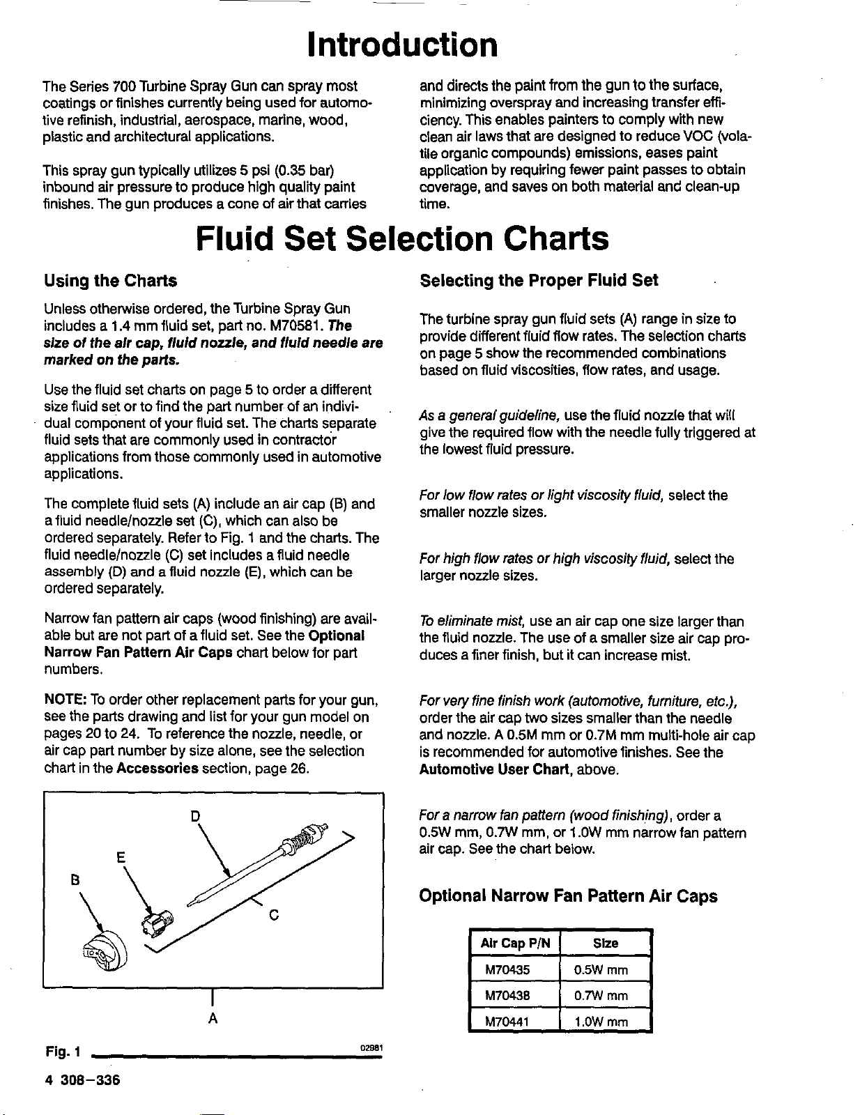
The complete fluid sets
afluid needlelnozzle set
ordered separately. Refer to Fig.
fluid needlelnoule
assembly
ordered separately.
mm fluid set, part no.
(A)
(C),
(C)
set includes a fluid needle
(D)
and
a
fluid nozzle
include an air cap
which can also be
M70581.
1
and the charts. The
(E),
which can be
The
(a)
and
minimizing overspray and increasing transfer emciency. This enables painters to comply with new
VOC
clean air laws that are designed to reduce
tile organic compounds) emissions, eases paint
application by requiring fewer paint passes to obtain
coverage, and saves on both material and clean-up
time.
(vola-
Charts
Selecting the Proper Fluid Set
The turbine spray gun fluid sets
provide different fluid flow rates. The selection charts
on page
based on fluid viscosities, flow rates, and usage.
As
give the required flow with the needle fully triggered at
the lowest fluid pressure.
For low flow rates
smaller nozzle sizes.
For
larger nozzle sizes.
5
show the recommended combinations
a general guideline, use the fluid nozzle that will
or
light viscosily fluid, select the
high
flow rates
or
high viscosity fluid, select the
(A)
range in size to
Narrow fan pattern air caps (wood finishing) are avail-
set.
able but are not part of afluid
Narrow Fan Pattern Air Caps chart below for part
numbers.
NOTE To order other replacement parts for your gun,
see the parts drawing and list for your gun model on
pages
20
to
24.
To reference the nozzle, needle, or
air cap part number by
chart in the Accessories section, page
size
A
See the Optional
alone, see the selection
26.
To
eliminate mist, use an air cap one size larger than
the fluid nozzle. The use of a smaller size air cap pro-
duces a finer finish, but it can increase mist.
For very fine finish work (automotive, furniture, etc.),
order the air cap
and nozzle.
is recommended for automotive finishes. See the
Automotive User
For a narrow
0.5W
mm,
air cap. See the chart below.
two
sizes smaller than the needle
A
0.5M
mm or
Chart,
fan
pattern (wood finishing), order a
0.7W
mm, or
0.7M
mm multi-hole air cap
above.
1
.OW
mm narrow fan pattern
Optional Narrow Fan Pattern Air Caps
Alr
Cap
M70435
~
M70438
M70441
P/N
Slze
0.5W
0.7W
1
.OW
rnm
mm
mm
Fig.
1
4
308-336
02981
Page 5
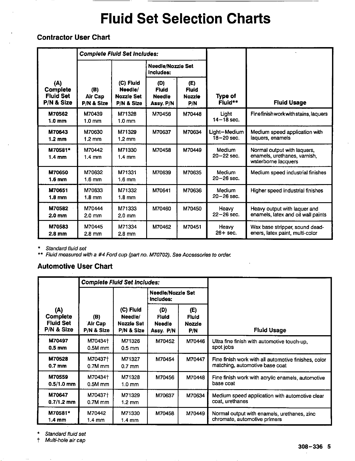
Fluid
Contractor User Chart
I
(4
Complete
Fluid Set
&
Size
PIN
Complete
Alr
P/N & Slze
Fluid
(6)
Cap
Set
Set Includes:
(C)
Fluld
Needlel Fluld Fluld
Selection
NeedlelNozzle Set
Charts
M70562
1.0
mm
M70643
mm
1.2
M70581'
mm
1.4
M70650
mm
1.6
M70651
mm
1.8
2.0
mm
M70583
2.8
mm
*
Standard fiuid set
**
Fluid
measured with
Automotive User Chart
M70439
1.0 mm
M70630
1.2 mm
M70442
1.4 rnm
M70632 M70639 M70635
I
1.6mm
I
M70633
1.8 mm 1.8 mm
M70444 M71333
mm
a
I
I
#4
Ford cup (part no.
M71328 M70456 M70446
1.0 mm
M71329 M70637 M70634
I
1.2 mm
M71330
1.4 mm
?ilz
M71332
M71334 M70445
2.8 mm 2.8
I
M70456
I
I
M70641
I
M70460
M70702).
Light
14-18 sec.
I
I
M70449
I
I
M70636
I
M70450
M70451 M70462
See Accessories to order:
Medium Normal output with laquers,
Medium Medium speed industrial finishes
20-26 sec.
Medium Higher speed industrial finishes
20-26 sec.
Heavy
22-26 sec.
Heavy
26+ sec. eners. latex Daint. multi-color
Finefinishworkwithstains,laquers
waterborne lacauers
I
I
enamels, latex and oil wall paints
I
Heavy output with laquer and
Wax
base stripper, sound dead-
I
I
Comdete Fluid Set Includes:
I
(4
Complete
Fluid Set
&
Size
PIN
M70497 M70434t
mm
0.5
M70528
0.7
mm
M70559
.O
0.511
M70647
0.711.2
M70581*
mm
1.4
*
Standard fluid set
t
Multi-hole'air cao
~ M70437t
~ 0.7M mm
mm
mm
(6)
'Alr
Cap
PIN & Slze
0.5M mm
M70434t
0.5M mm
M70437t
0.7M mm
M70442
1.4 mm
I
(C)
Fluld
Needlel
Noale
Set
&
Slze
PIN
M71326
0.5 mm
M71327
mm
0.7
M71328 M70456
1.0 mm
1.2 mm
M71330 M70458
NeedleINoale
I
Includes:
(Dl
Fluld
Assv.
PIN
I
M70454
~~
Set
I
I
(E)
Fluld
Noale Needle
PIN
M70446 M70452
M70447
M70446
M70634
M70449
Ultra fine finish with automotive touch-up,
spot jobs
Fine finish work with all automotive finishes, color
matching, automotive base coat
Fine finish work with acrylic enamels, automotive
base coat
Medium speed application with automotive clear
coat, urethanes
Normal output with enamels, urethanes, zinc
chromate, automotive primers
Fluid Usage
~ ~~~~
308-336
5
Page 6
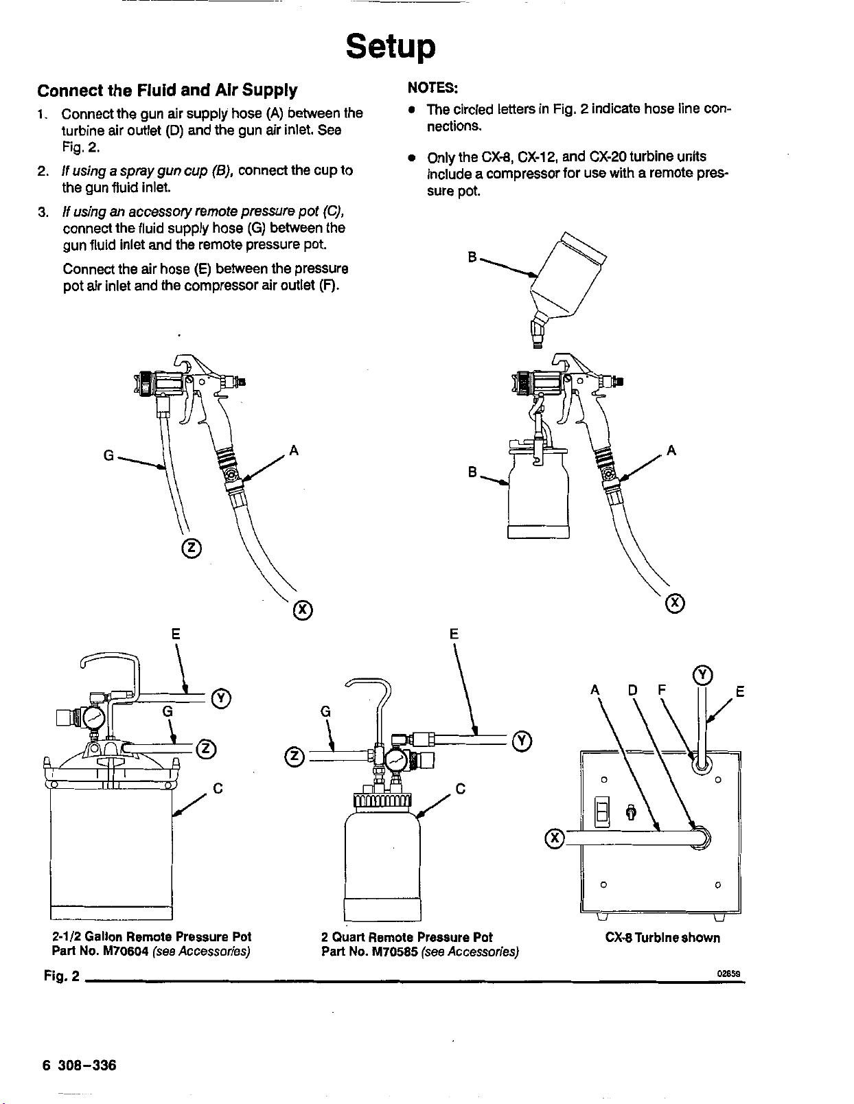
Setup
Connect the Fluid
1.
Connect the gun air supply hose
turbine air outlet
and
Air Supply
(A)
between the
(D)
and the gun air inlet. See
Fig. 2.
2.
If
using
a spray
gun
cup
(B),
connect the cup to
the gun fluid inlet.
3.
Musing
connect the fluid supply hose
an
accessory remote pressure pot (C),
(G)
between the
gun fluid inlet and the remote pressure pot.
Connect the air hose
(E)
between the pressure
pot air inlet and the compressor air outlet
(F).
E
2-112
Gallon Remote Pressure Pot
Part
No.
Fig.
M70604
2
(see
Accessories)
E
2
Quart Remote Pressure Pot
No.
Part
M70585
(see Accessories)
CX-8Turblne shown
02859
6
308-336
Page 7
Setup
Prepare the Fluid
1.
Always strain the fluid before spraying; this
if
includes color, reducer and hardeners
2.
When using a turbine spray system, you need
use a slower drying reducer or thinner to compensate for the faster drying time caused by the
warm air of the turbine.
-
Paint Reduction
Reduce and catalyze all paint to manufacturer’s specifications. To compensate for the faster drying time
turbine systems, use a reducer one-step slower than
what is used for conventional air spray.
Paint Reduction
Reduce and catalyze all paint to manufacturer’s spec-
If
ifications.
mix the fluid
proper reducer, testing the fluid until you have the correct spraying consistency.
no reductions are given, first thoroughly
to
Automotive Type Finishes
-
Industrial
be sprayed. Then gradually mix in the
Do
not over reduce.
or
Domestic Coatings
used.
to
of
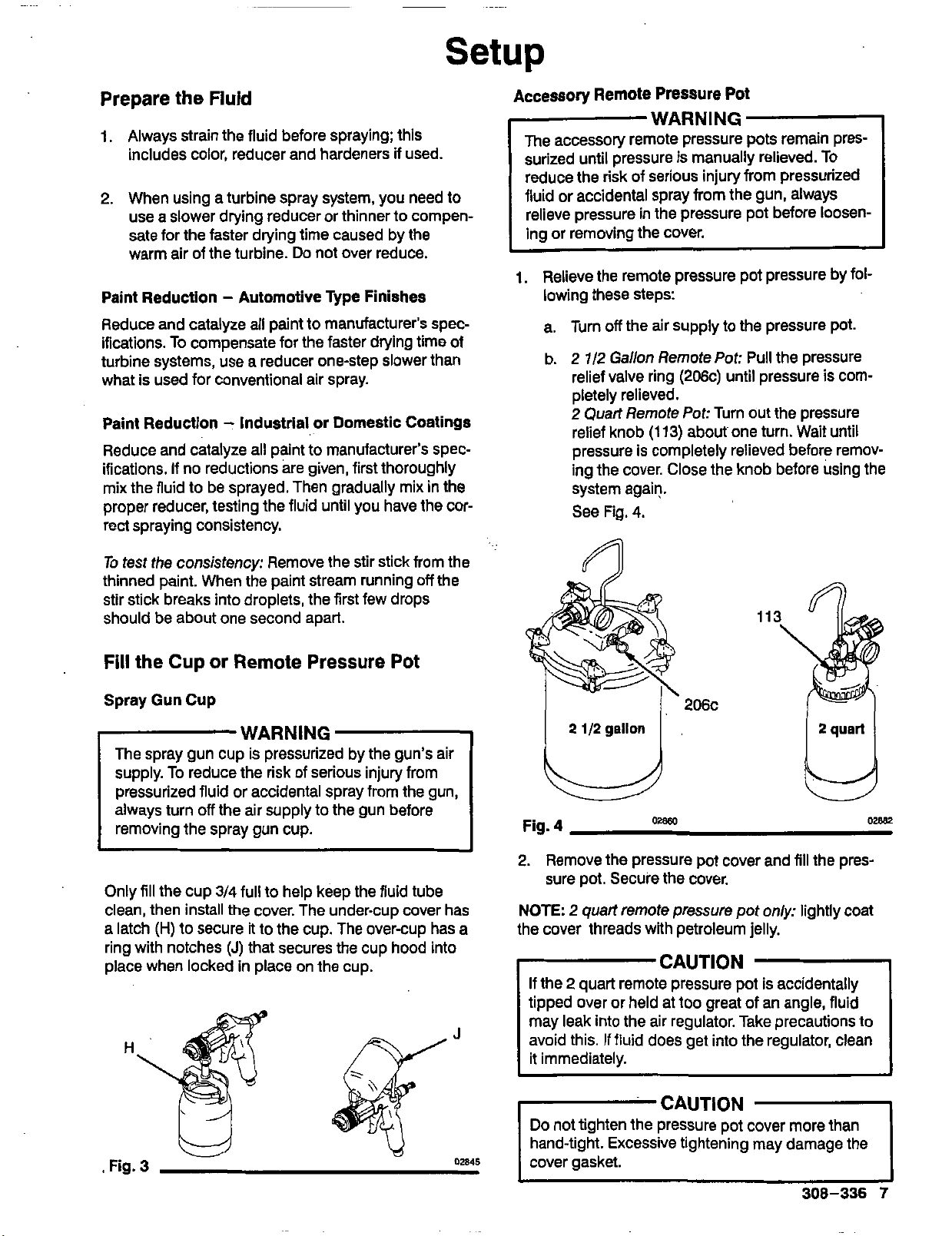
Accessory Remote Pressure Pot
WARNING
The accessory remote pressure pots remain pres-
surized until pressure is manually relieved. TO
reduce the risk of serious injury from pressurized
fluid or accidental spray from the gun, always
relieve pressure in the pressure pot before loosening or removing the cover.
1.
Relieve the remote pressure pot pressure by fol-
lowing these steps:
off
a. Turn
b.
2
relief valve ring (206c) until pressure is com-
pletely relieved.
2
relief knob
pressure
ing the cover. Close the knob before using the
system again.
See Fig.
the air supply to the pressure pot.
7/2 Gallon Remote
Quart Remote
(113)
is
completely relieved before remov-
4.
Pot:
Pull the pressure
Pot:
Turn out the pressure
about one turn. Wait until
To
test the consistency: Remove the stir stick from the
off
thinned paint. When the paint stream running
stir stick breaks into droplets, the first few drops
should be about one second apart.
Fill
the Cup
Spray Gun Cup
or
Remote Pressure
the
Pot
WARNING
The spray gun cup is pressurized by the gun’s air
supply. To reduce the risk of serious injury from
pressurized fluid or accidental spray from the gun,
always turn
removing the spray gun cup.
Only fill the cup
clean, then install the cover. The under-cup cover has
a latch
ring with notches
place when locked in place on the cup.
off
the air supply to the gun before
3/4
full to help keep the fluid tube
(H)
to secure it to the cup. The over-cup has a
(J)
that secures the cup hood into
Fig. 4
2.
Remove the pressure pot cover and fill the pressure pot. Secure the cover.
NOTE:
the cover threads with
2
quart remote pressure pot
petroleum jelly.
only:
lightly coat
CAUTION
If the 2
tipped
may leak into the air regulator. Take precautions to
avoid this. If fluid does get into the regulator, clean
it immediately.
quart remote pressure pot
over or held at too great of
is
accidentally
an angle, fluid
Do
not tighten the pressure pot cover more than
hand-tight. Excessive tightening may damage the
cover gasket.
308-336
7
Page 8
Prepare the Surface
to
be Sprayed
Setup
1.
Turn the turbine and compressor
Off.
To achieve proper adhesion, make sure the Surface
be sprayed
is
completely clean.
to
Operating the Turbine
WARNING
Sparking can be expected in the normal operation
of the turbine motor. Sparks could ignite fumes
from flammable liquid, dust particles and other
flammable substances in the spray area, and
cause serious injury and property damage. Be
sure
to
follow the precautions below:
0
When flammable liquid
flushing or cleaning equipment, the turbine
must be placed at least 20 feet
from areas where hazardous concentrations of
flammable vapors are likely
0
Use additional air hose
that the turbine
is
ventilated area.
0
Never place the turbine inside a spray booth!
Use this equipment outdoors or in extremely
'
well ventilated areas.
0
Avoid all ignition sources such as static elestricity from plastic drop cloths, open flames
such as pilot lights, hot objects such as ciga-
rettes, arcs from connecting or disconnecting
power cords or turning light switches on and
off.
Extinguish or remove all sources of ignition.
is
sprayed or used for
(6.1
m) away
to
occur.
if
necessary
to
ensure
operated in a clean, dry, well
2. Unplug the turbine from the power source.
3.
Loosen the four main filter screws and remove the
filter; replace the main filter and prefilter
if
they
are dirty.
4.
Hand spin the cooling fan on the compressor for
a few revolutions.
5.
Reassemble the turbine.
6.
Plug in the turbine and turn
it
on. The compressor
should start.
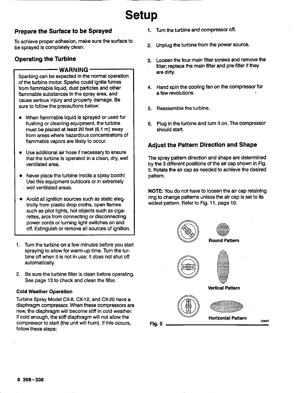
Adjust the Pattern Direction and Shape
The spray pattern direction and shape are determined
3
by the
5.
pattern.
NOTE
ring
widest pattern. Refer
different positions of the air cap shown in Fig.
Rotate the air cap as needed
You do not have
to
change patterns unless the air cap
to
to
Fig.
to
achieve the desired
loosen the air cap retaining
11,
page
IO.
is
set
to
its
1.
Turn the turbine on a few minutes before you start
spraying
bine
to
allow for warm-up time. Turn the tur-
off
when it
is
not in use; it does not shut
off
automatically.
2. Be sure the turbine filter is clean before operating.
See
page
13
to
check and clean the filter.
Cold
Weather Operation
Turbine Spray Model CX-8, CX-12, and CX-20 have a
diaphragm compressor. When these compressors are
new, the diaphragm will become
If
cold enough, the stiff diaphragm will not allow the
to
compressor
start (the unit will hum).
stiff
in cold weather.
If
this occurs,
follow these steps:
8 308-336
Fig. 5
Round
Vertical
Pattern
Pattern
Horlzontal
Pattarn
m817
Page 9
Setup
Adjust
the
Spray
Paitern
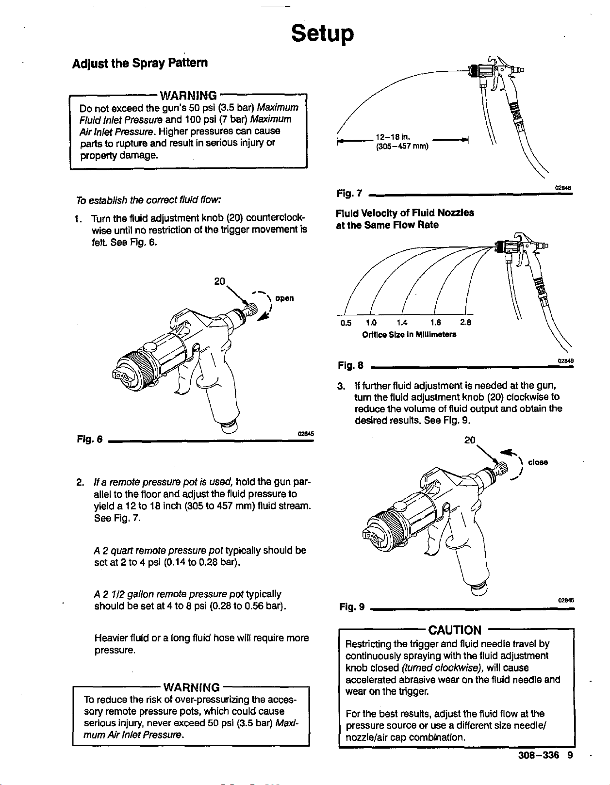
WARMING
Do
not exceed the gun's
Fluid lnlet Pressure and
Air
inlet
Pressure. Higher pressures can cause
parts to rupture and result in serious injury or
properly damage.
L
To
establish the correct fluid
1.
Turn the fluid adjustment knob
wise until no restriction of the trigger movement is
felt. See Fig.
6.
50
100
psi
(3.5
psi
flow:
bar)
(7
bar)
(20)
counterclock-
Maximum
Maximum
Fig.
7
Fluid Velocity
at the Same Flow Rate
Orlflce
of
Fluid Nozzles
Size
In
Millimeters
m1u8
u
Fig.
6
2.
If a remote pressure pot
allel to the floor and adjust the fluid pressure to
yield
a
12
to
18
inch
(305
See Fig.
A
2
set at
A
2
should be set at
Heavier fluid or a long fluid hose
Dressure,
7.
quart remote pressure pot typically should be
2
to 4 psi
1/2
gallon remote pressure pot typically
(0.14
4 to
to
8
U
is
used, hold the gun par-
to
457
mm) fluid stream.
0.28
bar).
psi (0.28 to
0.56
will
require more
WARNING
To
reduce the risk of over-pressurizing the acces-
sory
remote pressure pots, which could cause
50
psi
(3.5
serious injury, never exceed
mum
Air
Inlet Pressure.
bar)
bar).
Maxi-
me45
Fig.
8
3.
if
further fluid adjustment is needed at the gun,
turn the fluid adjustment knob
reduce the volume
desired results. See Fig.
of
fluid output and obtain the
9.
(20)
clockwise to
20
U
Fig.
9
CAUTION
Restricting the trigger
continuously spraying
knob closed (turned clockwise), will cause
accelerated abrasive wear on the fluid needle and
wear on the trigger.
For the best results, adjust the fluid flow at the
pressure source or use a different
nozzlelair cap combination.
and fluid needle travel by
with the fluid adjustment
size
needle/
02849
me45
308-336
Page 10

Setup
Adjust
To
4.
5. The Air Control Valve
the Spray Pattern
establish the corfect air
Test the spray pattem and atomization while hold-
6
ing the gun about
from the test piece.
bine hose controls both the atomizing air and the
pressure in the spray gun cup (if used). See Fig.
10.
Adjust the air control valve
to 8 inches (150 to
(continued)
flow:
(M)
on the end of the tur-
as
needed.
200
mm)
M
Fig.
10
02850
Adjust
Change the pattem size by turning the air cap retaining ring in for a wide pattern or out for a narrow pattern. See Fig. 11. For a smoother finish, use a narrow
pattern. For more fluid output, use a wide pattern.
NOTE
out, the fluid flow will stop or flutter.
Normal
Spray
Pattern
Wider
Spray
Pattern
the
Pattern
If
the air cap retaining ring
Size
Is
turned
too
Air Cap
with
Fluid Nozzle
Turn
Air
Retaining Ring In
c
far
flush
Cap
NOTES
To
control over-spray mist, use only as much air as
is necessary for the fluid being sprayed. The
less
lighter the fluid, the
If
atomization
procedure above, the fluid may need
further or a different fluid set may be required.
Refer
to
set
or
page 7 to prepare the fluid.
is
unacceptable after following the
pages 4 and 5 to select the proper fluid
air required.
to
be thinned
Narrower
spray
Pattern
Fig.
11
Turn Air Cap
Retaining Ring
Out
-
02851
10
308-336
Page 11

Shutdown
WARNING
The spray gun cups and accessory remote pressure pots remain pressurized until pressure is
manually relieved. To reduce the risk of serious
injury from pressurized fluid or accidental spray
from the gun, always relieve pressure in the cup or
pressure pot before checking or servicing any part
of the spray sysfem; before installing, cleaning or
changing fluid nozzles: before loosening or removing the accessoly remote pressure pot cover; and
whenever you stop spraying.
1.
When spraying
to the gun.
2.
If
using a remote pressure pot, relieve
by following these steps:
a. Turn
is
finished, turn
off
the air supply to the pressure pot.
off
the air supply
its
pressure
206c
2
1/2
gallon
ULJ
Fig.
12
02860
113
MBB2
2
1/2
b.
Gallon Remote
relief valve ring (206c) until pressure
pletely relieved.
2
Quart
Remote
relief knob
pressure
ing the cover. Close the knob before using the
system again.
See Fig. 12.
(1
13)
is
completely relieved before remov-
Pot:
Pull
the pressure
is
Pot:
Turn
out
the pressure
about one turn. Wait until
com-
NOTE
will allow the fluid in the fluid hose to drain back into
the remote pressure pot.
3.
4.
Elevate the spray gun and pull the trigger.
If
using a spray gun cup, unlatch the cup cover
and loosen or remove the cup from the cover to
relieve the cup pressure.
Clean the spray gun and cup as instructed on
pages
14 and
15.
This
308-336
11
Page 12

Spraying
General Spraying Techniques
1.
Select the proper fluid set for the fluid you are
4
and
See
5.
Fig.
13.
Then adjust
Air
Cap
with
Fluid
Turn
Air
Retaining
-
spraying. See pages
2.
When fluid
fluid nozzle and air cap adjusted to the "normal
spray pattern" position.
as needed.
Normal
spray
Pattern
Wider
Spray
Pettern
is
first being applied, start with the
Flush
Nozzle
Cap
Ring
Techniques
3.
Keep the gun perpendicular
maintain a consistent distance
8
In
inches
to
sprayed. See Fig.
Always have the spray gun in motion before trig-
4.
gering
piece in a straight, smooth stroke, maintaining the
same speed and distance. Release the trigger at
the end of the stroke.
5.
To obtain an even finish, overlap previous strokes
by the same amount, generally
6.
Apply a full, wet coat whenever possible.
Automotive Spraying Techniques
(150
it.
Move the spray gun across the work-
to
to
the surface and
of
approximately
200
mm) from the object being
14.
50%
overlap.
6
Fig.
13
Turn Air Cap
Retaining
Ring
Out
-
02851
1.
When blending spots, work from the outside in.
2.
Two lengths
mended when applying automotive finish coats,
The additional hose will allow the air to cool for
better flow.
of
20
foot
(6.1
m) hose are recom-
12
308-336
~~
RIGHT
WRONG
0783
Page 13

Spraying
Techniques
Prolonged Overhead or Downward Spraying with a
For
prolonged overhead spraying, loosen the fluid
(N)
tube nut
half turn. See Fig.
(36) in the back side of the cup
will be sprayed.
36
Fig.
15
and turn the entire cup assembly one-
15.
This will position the fluid tube
so
the entire contents
Forpro/onged downwafd spraying, make sure the
fluid tube (36)
I
Flg.
Cup
16
is
positioned
as
shown in Fig. 16.
W2
Turbine Filter Maintenance
The turbine systems are lifetime lubricated. The only
maintenance required is filter cleaning and replace
ment.
The turbine main filter and pre-filter must be clean at
to
all times
and atomize the fluid. Check the filters weekly, minimum. Replace the prefilter as required.
NOTE
place a piece of paper against the air intake filter.
the air intake holds the paper in place, the filter
okay.
To
clean the main filter:
1.
Turn
2.
Loosen the four main filter screws.
provide sufficient air flow to cool the motol
To
check the filter, turn on the turbine and
off
and unplug the turbine.
If
is
3.
Remove the main filter and clean it by following
one of the following three methods:
0
Tap the filter gently on a flat surface, dirty side
down.
0
Direct compressed air
mum) through the filter panel in the opposite
direction of the arrows on the side of the filter.
0
Soak the filter for
mild detergent. Rinse the filter until it
Air dry the filter; do not use compressed air.
-
To avoid damage
tric shock, never install a damp filter in the turbine.
WARNING
to
the turbine and possible elec-
Maintenance continued on
(100
psi
[7
bar] maxi-
15
minutes in water and a
is
clean.
next
page.
308-336
13
Page 14

Maintenance
WARNING
The spray gun cups and accessory remote pres-
sure pots remain pressurized until pressure is
manually relieved. To reduce the risk of serious
injury from pressurized fluid or accidental spray
from the gun, always relieve pressure in the cup or
pressure pot before checking or servicing any part
of the spray system; before installing, cleaning or
changing fluid nozzles; before loosening or removing the accessory remote pressure pot cover; and
whenever you stop spraying.
6.
Relieve the pressure pot pressure, following
2.a and b, above.
7.
Disconnect the air and fluid hoses from the gun.
8.
Clean and lubricate
pages
15
and
Flushing the Spray Gun
1.
Turn
off
the air supply to the gun.
16.
the
gun
as
instructed on
and
Cup
steps
NOTES
0
Check for any fluid leakage from the gun and fluid
hoses. Tighten fittings or replace equipment as
needed.
Flush the gun before changing colors and whenever you are done spraying.
CAUTION
Clean all parts with a solvent Compatible with the
fluid being sprayed and compatible with the spray
gun and cup or accessory remote pressure pot
wetted parts. See the Technical
cover.
Data
on the back
Flushing the Spray Gun Using a Remote
Pressure Pot
1.
Turn
off
the air supply to the gun.
2.
Relieve the pressure pot pressure by following
these steps:
off
a. Turn
the air supply to the pressure pot.
2.
Unlatch the cup cover and remove the cup from
the cover.
3.
Turn the air cap to the round pattern position and
turn the air control valve
reduce the solvent mist.
@
1
Fig.
17
4.
Fill the empty cup with about
mm)
of
compatible solvent and reinstall the cup.
Be sure the cover
5.
Turn on the air to the gun.
6.
Point the gun down into a container and flush
until the solvent runs clean. See Fig.
is
secured.
so
it's half open to
See
Fig.
17.
Alr
Cap
Round
Pattern
Posltlon
1-1/2
inches
(38.1
18.
me41
2
7/2
b.
3.
Fill the pressure pot with compatible solvent.
4.
Turn the air cap to the round pattern position and
turn the air control valve
reduce
5.
Flush the spray gun, using compressor air only.
Point the gun down into a container and flush
until the solvent runs clean.
14
308-336
Gallon
relief valve ring (206c) until pressure
pletely relieved.
2
Quart
relief knob
pressure
ing the cover. Close the knob before using the
system again.
See Fig.
the
Remote Pot: Pull the pressure
is
Remote
is
12,
solvent mist. See Fig.
Pot:
Turn out the pressure
(113)
about one turn. Wait until
completely relieved before remov-
page
11.
so
it's
haif open to
17.
com-
Fig.
18
7.
Turn
off
the air to the gun.
8.
Disconnect the air supply and remove the cup
from the gun. Clean and lubricate the gun as
instructed on pages
15
and
16.
028u
Page 15

Maintenance
Clean the Spray Gun
1.
Clean the gun and cup by hand with a compatible
solvent or place them in a gun washer with the
trigger held open; cycle the washer as necessary
to clean the gun.
4.
Soak the air cap, detent plate and fluid nozzle in
solvent. Clean the air car, and fluid nozzle daily,
.~
minimum, with solvent and the brush (R), pro-.
vided. See Fig.
21.
Some applications require
more frequent cleaning. Keep all air cap holes
clean.
CAUTION
Clean air cap horn holes with a non-metallic item
to avoid permanently damaging them.
R
Fig.
19
2.
Remove the air cap retaining ring
spring
(27).
20.
3.
Trigger the gun while you remove the fluid nozzle
(19)
with
Fig.
20.
(25),
and detent plate (26). See Fig.
the
nozzle wrench
(29),
(P),
provided. See
air cap
CAUTION
Trigger the gun whenever you tighten or remove
the nozzle. This keeps the needle seat awayfrom
the nozzle seating surface and prevents the seat
from being scratched.
Me53
Fig.
21
5.
With the gun pointed down, clean the front of the
02858
gun, using the brush, and solvent.
6. Trigger the gun while you install the fluid nozzle
(19)
with the nozzle wrench
7. Install the spring (25) into the front of the gun.
8.
Install the detent plate (26) into the gun housing
with its open sockets
ent plate tab
ing. See Fig.
Install the air cap
9.
(U)
with the detent plate sockets
0
with the notch in the gun hous-
22.
(27),
(P).
See Fig. 20.
(S)
facing up; align the det-
aligning the air cap balls
(S).
See
Fig. 22.
Secure the air cap with the air cap retaining ring
(29).
NOTE
If
installed correctly, the air cap will snap into
4
definite positions, with no loose rotation between the
positions.
Fig.
20
OW
Fig.
22
10.
Lubricate the gun after cleaning
page
16.
n
%===??=
it
as instructed on
308-336
M968
15
Page 16

Service
Lubricating the Spray
After cleaning or servicing the gun, lubricate the parts
23
indicated in Fig.
cant or similar material. See page
cant.
0
All
threaded areas (A)
0
Trigger screws
0
Trigger
0
Fluid needle assembly
axle
with silicone-free spray gun lubri-
(8)
(C)
Gun
26
(D)
-
where indicated
to order lubri-
2.
Loosen the locking nut (14d) and turn the drum
(14c). See Fig.
3.
Turn the drum (14c) until the trigger has about
1/16 in.
(1.59
25.
mm) free travel before the needle
(14) is engaged and starts to move. See Fig.
4.
Lock the adjustment
5.
Make
sure
the spring
ing
(22),
then install the housing with the other
with
the locking nut (14d).
(23)
is
in place in the hous-
parts. Hand-tighten the housing.
25.
~
Fluid
Fig.
Needle
2
23
in.
(50.8
Assembly
mm)
02949.
Adjusting the Needle
The needle may need to be adjusted whenever you
change nozzle/needle sizes or to compensate for
wear.
To
adjust
the
needle:
1.
Remove the housing
gun. The fluid adjustment knob
spring (23-not shown) will come out with it. See
24.
Fig.
(22)
from the back of the
(20),
nut
(21),
om
and
Fig.
Fig.
24
25
02857
16 308-336
Page 17

Service
Adjusting
The needle packings require adjustment once a
month under normal use to ensure fluid does not leak
back through the needle packings. The needle packings must also be adjusted whenever
removed or adjusted.
To
adjust the needle packings:
1.
First flush the gun as instructed on page
2.
Remove the air cap retaining ring
(27),
26.
3.
Trigger the gun while you remove the fluid nozzle
(19)
Fig.
Trigger the gun whenever you tighten or remove
the nozzle. This keeps the needle seat away from
the nozzle seating surface and prevents the seat
from beina scratched.
ICAUTIOY
the Needle
spring
with the nozzle wrench
26.
(25),
Clean the gun as instructed on page
Packings
the
(29),
and detent plate
(P),
provided. See
needle
(26).
air cap
See Fig.
1
14.
is
15.
K
5.
Trigger the gun while you install the fluid nozzle
(19)
with the nozzle wrench
98
(P).
See Fig.
26.
Fig.
26
4.
Trigger the gun while you turn the packing
slightly clockwise with the packing wrench
provided.
packings.
The packings need very
well. If the needle binds, the packings are
tight; back the packing nut
needle should then move freely. If the packings
are over-tightened, they may be damaged and
need to be removed and replaced.
See
Fig.
27.
This will compress the
little
pressure to
off
1/16
turn. The
nut
(K),
seal
too
02854
(9)
6.
Install the spring
7.
Install the detent plate (26) into the gun housing
with its open sockets
ent plate tab
ing. See Fig.
8.
Install the air cap
(U)
with the detent plate sockets
Secure the air cap with the air cap retaining ring
(29).
NOTE
definite positions, with no loose rotation between the
positions.
If installed correctly, the air cap will snap into
Fig.
28
(25)
into the front of the gun.
(S)
facing
0
with the notch in the gun hous-
28.
(27),
aligning the air cap balls
up;
align the det-
(S).
See Fig.
308-336
28.
4
02868
17
Page 18

Troubleshooting.
Spray
Gun
Problems
PROBLEM
No or slow fluid flow, inter-
mittent spray, or fluttering
spray
CAUSE
Proper size fluid set is not being used.
Air cap is adjusted too far forward.
Gun
fluid
nozzle
blocked by dried paint,
aged.
Cup or pressure pot cover is not tight
enough or gasket is damaged.
Cup or pressure pot fluid tube
blocked by dried paint or is damaged.
Air flow to cup is blocked.
is
not tight enough, is
or
is dam-
SOLUTION
Select the proper fluid set for the fluid
being sprayed. See pages
Adjust the air cap
tion. See page
Tighten, clean or replace fluid nozzle.
lighten cover or replace gasket.
Clean or replace fluid tube.
To
check: remove the cup (leave
cover connected), trigger the gun and
check for air flow out of the cup lower
pressure tube.
freely, clean the air
to
10.
is not flowing
If
air
passage tubes.
4
and
5.
"normal" posi-
Fluid leaks at fluid nozzle
after the trigger is released
Poor spray pattern
Needle packings are not properly adjusted. Fluid
will effect fluid pressure and cause a
fluid build-up in the gun body.
Needle is not properly adjusted. Fluid
flow will be restricted if there is too
much free travel between the trigger
and needle.
Needle is not seating in the fluid
nozzle.
Air cap horn holes and/or fluid nozzle
plugged.
loss
though the packings
Clean the gun body with solvent and
the brush provided. Adjust the needle
packings as instructed on page
Adjust the needle as instructed on
page
16.
0
Check for a loose fluid nozzle or
bent nozzle or needle; tighten the
nozzle or replace parts as needed.
0
Check the needle adjustment; see
16.
page
0
Check the needle packings adjust-
ment; see page
Soak air cap and/or fluid nozzle in
vent. Clean air cap horn holes with
non-metallic item to avoid permanently damaging them. See page
17.
17.
a
sol-
15.
18
308-336
Page 19

Troubleshooting
Spray
Finish
'ROBLEM
Problems
-
)range peel finish - Paint
iurface not smooth
3lushing
-
Clear coatings
appear milky
CAUSE
Paint droplets too large.
Paint droplets drying too fast to properly flow out of gun.
Cold weather spraying.
~~~ ~ ~~
Moisture condensation is trapped
the lacquer when spraying
in
in
hot, hu-
mid conditions.
SOLUTION
Maintain proper spraying distance:
see page
12.
Keep the turbine air filters clean to
allow
full
air flow. See page
Do
not use an air hose that is to0
13.
long to provide sufficient atomization pressure.
If droplets are still too large,
reduce the fluid or use a smaller
air cap.
the
Keep
object being sprayed out of
direct sunlight. When spraying in
warmer temperatures, use a slower
evaporating solvent or a retarder.
Keep the fluid and the object being
to
sprayed as close
room temperature
as possible. When sprayed on a cold
surface, most paints will become too
thick to flow properly.
Allow the turbine to warm up a few
minutes before spraying.
Store the lacquer
off
concrete
floors, at room temperature.
Apply lighter coats and ailow for
proper drying time.
Use a slower evaporating solvent
or retarder.
Do
not spray
in
windy conditions.
Fish eyes
-
Small pools on
painted surface that will not
fill
Runsandsags
~ ~~
Solvent pops or bubbles
Silicone contamination from lubricants, grease, polish, or waxes on the
surface being sprayed.
Applying too much paint per pass for
the
drying
conditions.
Sprayed surface drying before solven
gas can be released.
Clean all parts with a cleaning solvent:
use a solvent rag and a clean rag to
wipe with. Replace rags as needed. If
the problem persists, use a fish eye
eliminator.
Move the
gun
faster or decrease
the fluid.flow.
Maintain proper spraying distance:
see page
12.
Reduce the amount of thinner or
use a faster drying thinner.
Apply fluid in lighter coats to allow
for proper evaporation.
Use the recommended thinners.
Follow the solutions, above, for
Orange peel finish-paint droplets
too large.
308-336
19
Page 20

Parts
for
Model
710
NOTE:
The
(181,
and fluid
available
page 5 for
air
needle
as
complete
pari
cap
(27).
assembly
fluid sets.
numbers.
fluid noale
(14)
See
are
37
38
NOTE
Wrap
around fluid tube
hose
(36).
(34)
20
308-336
Page 21

Parts
PTFE
for
Model
710
Ref
No.
1
2*
3*
4*
5*
6
7
8*
9*
10
11*
14
14a
14b
14c
14d
19
20
21
22
23
25*
26*
Part
No.
M70373
M70410
M70388
M70389
M70392
M70384
M70401
M70381
M70380
M70391
M70386
-
M70403
M70404
M70405
M70406
-
M70467
M70466
M70465
M70407
M70378
M70377
Description
GUN BODY
ACTUATOR, needle
PIN, actuator
AXLE, trigger
GUIDE, trigger
HOLDER, nozzle
FITTING, fluid inlet
PACKING KIT. fluid:
NUT, packing
TRIGGER
SCREWIBUSHING ASSY., trigger 2
NEEDLE
page 5 for part no.: Includes
items
14a-14d
-RING, driving
*SPRING, driving ring
DRUM
=LOCKING NUT, drum
FLUID NOZZLE,
page 5 for part no.
ADJUSTMENT KNOB, fluid
NUT, adjustment
HOUSING, adjustment
SPRING, needle return
SPRING, air cap
DETENT PLATE, air cap
axle
ASSY.;
See
See
chart
chart on
Qty
on
1
1
1
1
1
1
1
1
1
1
Ref
No.
27
29
30
31
32*
33
34*
35
36
37
38
39
40
42
43
44
51
52
53
55
Part
M70375
M70400
M70721
M70430
M70394
M70395
M70426
M70413
M70415
M70417
M70422
M71151
M70420
M70424
M70423
M70419
M71117
M71118
M70612
These
which
No.
-
parts
may
Description
AIR
CAP; See chart
part no.
RETAINING RING, air cap
QUICK DISCONNECT, turbine
O-RING; quick disconnect
SET
SCREW, quick disconnect
CONNECTOR, hose
HOSE, air pressure (upper)
CONNECTOR, hose
FLUID TUBE
YOKE, cup
LEVER, cup
COVER,
ELBOW,
NUT, locking
GASKET, cup; polyethylene:
See Accessories to order 5 pack
CUP: 1 quart
HOSE, air pressure (lower)
CONNECTOR, hose
FERRULE
TOOL
brush, T-wrench,
are
included
be
purchased sepafafe/y.
cup
air
pressure
KIT;
(not shown) Includes a
in
Repair
on
(1
liter)
&
nozzle wrench
Kit
page 5 for
M70290,
1
Qty
1
1
1
1
1
1
1
1
1
1
1
1
1
1
1
1
1
1
1
1
308-336
21
Page 22

Parts
for
Models
709HS
81
71OHS
NOTE:
Model
Model
709HS
710HS
includes
includes 3/4 quart (3/4
1/2
quart
(1/2
liter)
liter)
cup
cup
22
308-336
10
11*
NOTE
The air cap
fluid needle assembly
complete fluid sets. See page 5 for part numbers.
(27),
fluid
(14)
noale
are available
(IS),
and
as
02886
Page 23

Parts
PTFE
for
Models
709HS
&
710HS
Ref
No.
1
2*
3*
4*
5*
6
8*
9*
10
ll*
14
14a
14b
14c
14d
19
20
21
22
23
25*
26*
27
29
Part
No.
M71114
M70410
M70388
M70389
M70392
M70384
M70381
M70380
M70391
M70386
-
M70403
M70404
M70405
M70406
-
M70467
M70466
M70465
M70407
M70378
M70377
-
M70375
Description
GUN BODY
ACTUATOR, needle
PIN, actuator
AXLE, trigger
GUIDE, trigger
HOLDER, nozzle
PACKING KIT. fluid:
NUT, packing
TRIGGER
SCREW/BUSHING ASSY, trigger
NEEDLE ASSY; See chart
page 5 for part no.: Includes
items
14a-14d
*RING, driving
*SPRING, driving ring
DRUM
LOCKING NUT, drum
FLUID NOZZLE, See chart on
page 5 for part no.
ADJUSTMENT KNOB, fluid
NUT, adjustment
HOUSING, adjustment
SPRING, needle return
SPRING, air cap
DETENT PLATE, air cap
AIR
CAP; See chart on page 5 for
part no.
RETAINING RING, air cap
axle
on
~
Qty
1
1
1
1
1
1
1
1
1
2
1
1
1
1
1
1
1
1
1
1
1
1
1
1
Ref
No.
30
31
32*
33
34
35
36
37
30
39
40
41
42
43
44
45
46
47
55
*
Part
M70400
M70721
M70430
M70426
M71031
M71030
M71033
M71032
M71035
M71034
M71040
M71039
M71037
M71026
M71021
M71019
M71045
M70393
M71046
M70612
These parts are included
which may be purchased separately.
Description
No.
QUICK DISCONNECT, turbine
O-RING: quick disconnect
SET
SCREW, quick disconnect
SET SCREW, plug
FITTING, fluid inlet
NUT, fluid inlet
O-RING
O-RING
CUR 1/2 quart (1/2 liter);
Model
709HS only
CUR 3/4 quart (3/4 liter);
Model
NUT
FITTING
RING, cup
GASKET, cup; polyethylene:
See
COVER, cup
NUT 2
TOOL KIT; (not shown) Includes a
710HS only
Accessories to order 5 pack
HOSE, air pressure
ELBOW CONNECTOR, hose
ELBOW CONNECTOR, hose
brush, T-wrench, &nozzle wrench
in
Repair Kit
w
1
1
1
1
1
1
1
1
1
1
1
1
1
1
1
1
1
1
1
M70290,
308-336
23
Page 24

19
PTFE
Parts
for
Model
7IQP
Ref
No.
1
2'
3*
4*
5*
6
7
8*
9*
10
11*
14
14a
14b
14c
14d
19
Part
No.
M70373
M70410
M70388
M70389
M70392
M70384
M70401
M70381
M70380
M70391
M70386
-
M70403
M70404
M70405
M70406
-
7
'
Description
GUN BODY
ACTUATOR, needle
PIN, actuator
AXLE, trigger
GUIDE, trigger axle
HOLDER, nozzle
FITTING, fluid inlet
PACKING KIT, flu
NUT, packing
TRIGGER
SCREW/BUSHING ASSY, trigger 2
NEEDLE ASSY.: See chart on
5
page
items 14a- 14d
*SPRING, driving ring
FLUID NOZZLE, See chart on
page 5 for part no.
for part no.: Includes
RING, driving
DRUM
LOCKING NUT, drum
YU
10
11*
Qty
1
1
1
1
1
1
1
1
1
1
1
1
1
1
1
1
NOTE
The air cap
fluid needle assembly
complete fluid sets. See page
Ref
No.
20
21
22
23
25*
26*
27
29
30
31
32*
33
55
Part
No.
Description
M70467
M70466
M70465
M70407
M70378
M70377
-
M70375
M70400
M70721
M70430
M70426
M70612
These parts are included
which may be purchased separafely.
ADJUSTMENT KNOB, fluid
NUT,
adjustment
FITTING, gun
SPRING, needle return
SPRING, air cap
DETENT PLATE, air cap
AIR CAP: See chart on page 5 for
part no.
RETAINING RING,
QUICK DISCONNECT, turbine
O-RING; quick disconnect
SET
SCREW,
SET SCREW,
TOOL KIT; (notshown) Includes a
brush, T-wrench,
(27),
in
Repair
fluid nozzle
(14)
are available as
air
quick disconnect
plug
B
(W),
and
5
for part numbers.
cap
nozzle wrench
Kif
M70290,
028M
Qtv
1
1
1
1
1
1
1
1
I
1
1
1
1
24
308-336
Page 25

2
112
50
psi
2 112
Gallon
gallon
Pressure Pot
(3.5
bar) Maximum Inlet Air Pressure
(9.5 liter)
M70604
capacity,
aluminum
Accessories
2
Quart
Pressure Pot
50
psi
(3.5
bar) Maximum Inlet
2
quart
tank.
(2 liter)
capacity,
M70962
aluminum
102 119
Air
Pressure
cup.
205
204
203
202
206f
206b
206c
201
-
206a
206d
-
206
121
125
124
123
Ret.
No.
/
4
Part
No.
LX
Descrlptlon
118
103
101
105
113
111
107
104
106
108
logel
w.
'
Ret.
No.
201 M70670 PRESSURE GAUGE
202
203 M70671
204 M70805
205
206
206a M70667 *COUPLING
206b M70676 *O-RING, pressure relief valve
206c
206d M70616 *GASKET, standard; EPDM
206e
206f M70688
Part
No.
M70674
M70675
M71433
M70686
M70617 GASKET, solvent resistant; Thiokal
M70683
Descrlptlon
HEX NIPPLE, 1/4
PRESSURE REGULATOR
ELBOW, 90"
QUICK DISCONNECT, male
PRESSURE POT ASSEMBLY
Includes replaceable items 206a-20611
*
PRESSURE RELIEF VALVE
(optional-must order separately)
POT, 2 1/2 gallon (9.5 liter),
galvanized steel
.COVER
in.
02861
w.
101 M70670
102 M70727
103 M70671
104 M70731
105
106 M70733
107 M70734
108 M70735
109 M70730
110 M70729
111
112 M70628
113 M70726
114 M70725
1
115 M70724
1
116 M70723
1
117
1
118 M70675
1
119 M70805
120 M71491
1
121 M71470
1
122 M70854
1
123 M70402
1
124 M70397
125 M71412
1
126 M70399
1
1
M70895
M70728
M70722
PRESSUREGAUGE
SAFETY VALVE
PRESSURE REGULATOR
SPRING
REDUCER
BRACKET
VALVE
SCREW
2
quart (1.94 liter), aluminum
POT,
FLUID TUBE
COVER
GASKET, polyethylene
PRESSURE RELIEF KNOB
FITTING
FLUID OUTLET
NllT
HANDLE
PLUG, male, quick disconnect
ELBOW, 90"
HOSE, fluid; 5
1/4 in. (6.35 mm) ID
HOSE, air; 4.5
HOSE CLAMP
QUICK DISCONNECT, female
AIR CONTROL VALVE
O-RING, air valve
QUICK DISCONNECT, male
ft. (1.5 m) long;
ft. (1.4 m) long
1
1
1
1
1
1
1
1
1
1
1
1
1
1
1
1
1
1
1
1
1
1
1
1
1
1
Accessories continued on next ?age.
308-336
25
Page 26

Accessories
NOTE For information on making selections according to the type of
Needle, Nozzle, and Complete
Listed
by
size.
Fluid
Set Chart
-
*
Fluid needlelnoule
**
Complete fluid
air cap.
Fluid
Noale
P/N
M70446
M70447
M70448
M70634
M70449
M70635
M70636
M70450
M70451
set
includes the needle and nozzle.
set
includes needle, nozzle. and standard
Fluld Needle1
Nozzle
Set*
M71326 M70497
Complete
Fluid Set
**
fluid
being sprayed,
Air Cap Chart
Listed
t
t
tt
see
pages 4 and
by
size.
Standard
Orltlce
0.5
mm
0.7 mm
1.0 mm
1.2 mm
1.4 mm
1.6 mm
1
.8
mm
2.0 mm
2.8 mm
Multl-holm
(example:
Narrow fan pattern air cap. Size
marked with a W (example: 05W).
Alr
Cap
PIN
M70434t
M70437t
M70439
M70630
M70442
M70632
M70633
M70444
M70445
air
cap.
05M).
Size
marked
5.
Narrow
Fan Air
Cap PIN
M70435tt
M7043Btt
M70441
with
tt
an
M
User Kit
Used with CX-5, CX-7, CX-9, CX-10, and CX-20.
Includes:
User Kit
Used with
Includes:
Lubricant
One
lubricant for fluid seals and wear areas.
26 308-336
M70704
Pari
No. Descrldlon
M70562 1.0 mm Fluid Set
M70582 2.0 mm Fluid
1
M70425
M70464 Fluid Strainer
M70395 Upper
-
M71449
CX-8
Pari
No.
M70439
M70444
M70448
M70450
M71425
M70460
M70456
M70377
M70376
11 1-265
4
02.
(1
Quart Under-cup
Parts
Box
and
CX-12.
DescrlDtlon
1
.O
Air
2.0
Air
1.0 Fluid Nozzle
2.0
Fluid Nozzle
5 pack of Polyethylene Gaskets for
2 quart (2 liter) pressure pot
2.0 Needle Assembly
1
.O
Needle Assembly
Detent Plate
Spring
13
gram) tube sanitaty (non-silicone)
Set
Air
Pressure
with Compartments
Cap
Cap
Gaskets
Hose
Qtv.
1
1
1
.1
3
1
Qtv.
1
1
1
1
1
1
1
1
1
#4 Ford Viscosity Cup
To
measure viscosity
Blow Gun
For dusting and drying. With quick disconnect and air
control valve.
1
Quart
FRs
on cup part no. M70423 for air tight storage
fluid.
1
Quart
1
quart
1
Quart
5
pack
iiter) under-cup.
3/4
Quart
314
quart (314 liter) over-cup with lid.
314
Quart
5
pack of polyethylene gaskets for
(314 liter) over-cup.
Cup Check Valve
To
help prevent the cup from de-pressurizing after the
air is shut
M70703
(1
liter) Cup
(1
liter) Cup and Lid Assembly
(1
liter) under-cup with air tight lid.
(1
liter) Cup Gaskets
of
polyethylene gaskets for
(314
liter) Cup and
(314
liter) Cup Gaskets
off.
M70702
of
fluid.
Lid
M70610
M71007
M70427
use
Lid
Assembly
M71027
use
of
M70427
with 1 quart
with 3/4 quart
(1
M71047
~~
Page 27

Accessories
Fluid Strainer
Install on the end
to strain the fluid and help eliminate surface
blemishes and plugged tips.
Air Hose
For use
250
psi
(1
For connection between the pressure pot and compressor.
f
x
f quick-disconnect,
Air
Hose Extension
For use wlth the 2 quart
250
psi
(1
To
extend the length of pressure pot air hose
20
ft.
(6.10
1/4
in.
(6.35
Air Hose
For use
150 psi (10.5 bar) Maximum Working Pressure
For connection between the pressure pot and compres-
3
ft.
sor.
NOTE Quick-Disconnect
M70804
Female Quick-Disconnect
For use with air hose
male quick-disconnect on the
pressure pot.
Barbed Fitting
For use with air hose
compressor.
Air Control Valve
Install on turbine hose to control the atomizing air and
the pressure in the spray gun cup.
valve O-ring, order part no.
M70464
of
the cup or pressure pot fluid tube
100
mesh screen. Coupled,
M70666
wlth
the 2 quart
7.5 bar) Maximum Working Pressure
20
ft.
(6.10
7.5 bar) Maximum Working Pressure
m)
long, coupled,
mm)
braided.
M70803
wlth
the
2 112
(0.92
m)
long, coupled,
are
needed to connect the air hose.
M70804
(2
llter) pressure
m)
long, coupled,
114
in.
M70665
(2
liter) pressure pot
gallon
M70911
M70911
M70803
M70803
M70397
M71412.
(6.35
mm)
braided.
m
x
f
quick-disconnect,
(9.5
liter) pressure pot
1/4
in.
(6.35
and Barbed Fitting
to connect to the
2 112
gallon
to connect to the
To
replace the air
pot
M70666.
mm).
(9.5
liter)
Turbine Hose
100
psi
(7
bar) Maximum Working Pressure
For connection between the turbine and spray gun.
3/4
in.
(19
mm),
spring on turbine end.
v
M71451
M71453
Turbine Hose Extension
100
psi
(7
To
extend the length of turbine hose
M71453.
Fluid Hose
For use wlth the
175 psi
For connection between the pressure pot and spray
gun.
Fluid Hose Extension
For use with the
175psi
To
318
NOTE Fluid Hose Connector
ordered with
Fluid Hose Connector
For use with fluid hose extension
318
Coupled,
Part
No.
M71462
M71464
(12.1
25
ft.
(12.1
extend the length of fluid hose
in.
(9.53
Part
No.
M71480
M71484
npsm.
20
ft.
(6.10
m)
30
ft.
(9.15
m)
bar) Maximum Working Pressure
M71451
3/4
in.
(19
mm).
Lenath
20
ft. (6.10 m)
30
ft.
(9.15
m)
M71481
2 112
gallon
bar) Maximum Working Pressure
(7.63
m)
long, coupled,
2 112
gallon
bar) Maimum
mm).
the
fluid hose extension.
Lenath
20ft.
(6.10
30
ft.
(9.15
(9.5
(9.5
Working
M70693
m)
m)
M70693
liter) pressure pot
3/8
in.
(9.53
liter) pressure
Pressure
M71481.
must be
M71480
or
or
mm).
pot
Coupled,
M71484.
308-336 27
Page 28

The
PTFE
PTFE
WARRANTY
Graco warrants all equipment manufactured by it and bearing its name
date
of
sale by an authorized Graco distributor to the original purchaser for use.
ranty, Graco will, for a period of twelve months from the date of sale, repair or replace any part of the equipment proven defective.
This warranty applies only when the equipment is installed, operated and maintained in accordance with Gram's written recom-
mendations.
This warranty does not cover, and Graco shall not be
application, abrasion, corrosion, inadequate or improper maintenance, negligence, accident, tampering, or substitution of nonGraco component parts. Nor shall Graco be liable for malfunction, damage or wear caused by the incompatibility with Graco
equipment of structures, accessories, equipment or materials not supplied by Graco, or
tion, operation or maintenance of structures, accessories, equipment or materials not supplied by Graco.
This warranty is conditioned upon the prepaid return of the equipment claimed
for verification
equipment will be returned to the original purchaser transportation prepaid.
defect in material or workmanship, repairs will be made at a reasonable charge, which charges may include the
labor and transportation.
DISCIAIMERS AND LIMITATIONS
The terms of this warranty constitute purchaser's sole and exclusive remedy and are in lieu of any other warranties (express or
implied), lncludlng warranty
:iabiiities, including product liabilities. based on negligence or strict liability. Every form
damages or
action for breach
of
loss
Graco Warranty and Disclaimers
to
be
free
from defects in material and workmanship on the
As
purchaser's sole remedy for breach of this war-
liable
for, any malfunction, damage or wear caused by faulty installation,
the improper design, manufacture, installa-
to
the claim.
is expressly excluded and denied. In
of
If
the claimed defect is verified, Graco will repair or replace.free of charge any defective parts. The
of
merchantablllty or warranty
warranty must be brought within two
be defective
If
inspection of the equipment does not disclose any
of
fltness for a particular purpose, and
of
no
case shall Graco's liability exceed the amount of the purchase price. Any
(2)
years of the date
of
sale.
to
an authorized Graco distributor
of
any non-contractual
liability for direct, special or consequential
costs
of
mis-
parts,
EQUIPMENT
Graco makes no warranty, and disclaims all implied warrantles
respect to accessories, equipment, materials,
manufactured by Graco (such as electric motor, switches, hose, etc.) are subject to the warranty,
Graco will provide purchaser with reasonable assistance
Maximum
Maximum
Wetted
Bare
Spray
2
Remote
2-112
Remote
NOT
COVERED
BY
GRACO WARRANTY
or
Technical Data
Inlet
Fluid
Inlet
Air
Pressure
Parts
Spray
Gun
Gun
Cups
Quart
Accessoly
Pressure
Gallon
Accessory
Pressure
is
a
registered trademark
Pressure
.........
........
Pot
Pot..
........
...........
Stainless
50
100
Steel,
Hard-coated
Aluminum, Polyethylene
....
Aluminum,
........
of
the Corporation.
Polyethylene
Galvanized
EPDM
of
merchantablllty
components sold but not manufactured by Graco. These items sold, but not
in
making any claim for breach of these warranties.
and
fltness for a particular purpose, with
Graco Phone
psi
(3.5
bar)
psi
(7
bar)
~ ~~i~~~,
TEcffN'cAL
information
Graco
equipment:
Steel,
(standard)
Numbers
Ass'sTANcE~
or
assistance
1-800-543-0339
regarding
if
any,
of
their manufacturer.
the
repair
application
Toll Free
of
Sales Offlces: Atlanta, Chicago, Dallas, Detroit,
Forelgn Offlces: Canada; England; Korea: Switzerland: France: Germany: Hang Kong; Japan
GRACO INC.
RO.
BOX
1441 MINNEAPOLIS, MN 55440-1441
PRINTED
IN
U.S.A.
Los
308-336
Angeles, Mt. Arlington (N.J.)
1/94
 Loading...