

Page 1
INSTRUCTIONS 307–378
Rev.
H
INSTRUCTIONS
This manual contains important
warnings and information.
READ AND RETAIN FOR REFERENCE
Supersedes G
Model
Air
600
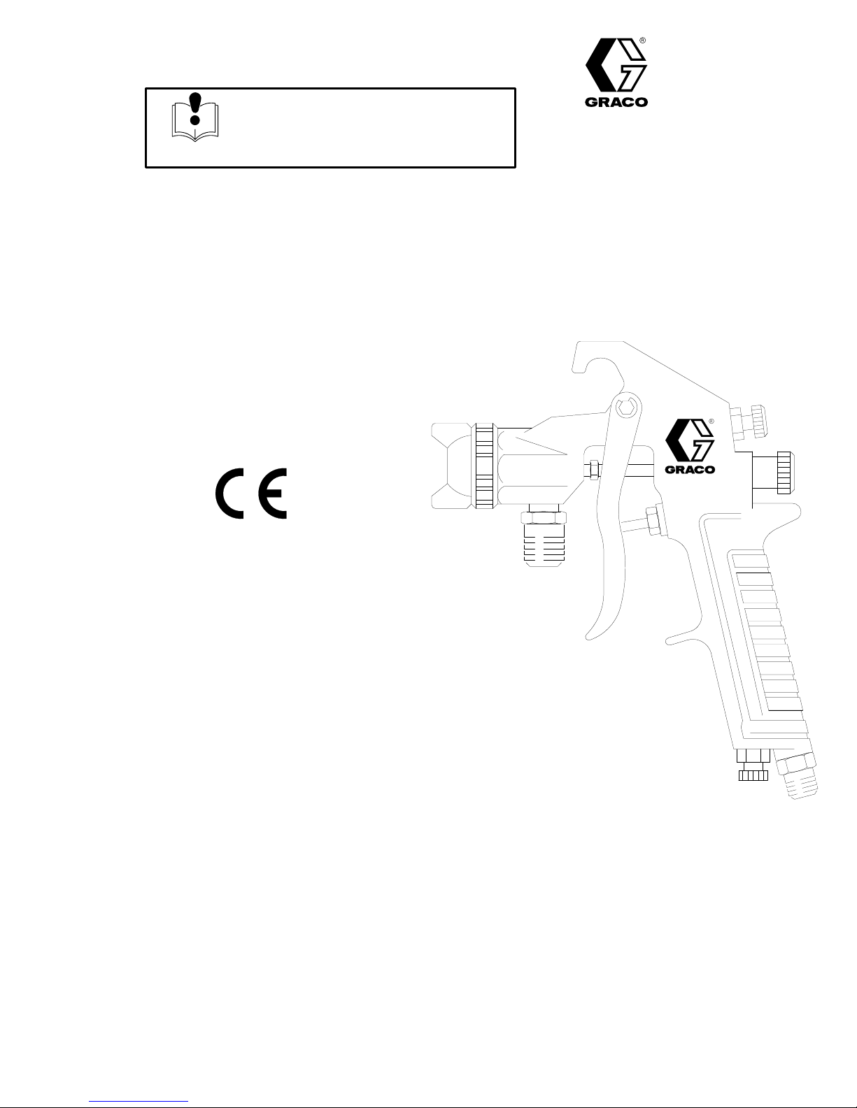
Spray Gun
100 psi (7 bar) Maximum Working Fluid Pressure
100 psi (7 bar) Maximum Working Air Pressure
See
the charts on pages 4 and 5 for complete air
spray gun ordering numbers and description.
Table
Warnings 2.
Ordering
Installation 6
Operation 8
Maintenance 9
Troubleshooting 10
Service 12
Parts 14
Accessories 16
Dimensional
Technical
Air
Flow Charts
Warranty 20
Graco T
. . . . . . . . . . . . . . . . . . . . . . . . . . . . . . . . . . . . .
Charts4. . . . . . . . . . . . . . . . . . . . . . . . . . . . . . . .
. . . . . . . . . . . . . . . . . . . . . . . . . . . . . . . . . . . . .
. . . . . . . . . . . . . . . . . . . . . . . . . . . . . . . . . . . . . .
. . . . . . . . . . . . . . . . . . . . . . . . . . . . . . . . . . . . . . . .
Data
. . . . . . . . . . . . . . . . . . . . . . . . . . . . . . . . . . . . .
oll-Free Phone Numbers
of Contents
. . . . . . . . . . . . . . . . . . . . . . . . . . . . . . . . . . . .
. . . . . . . . . . . . . . . . . . . . . . . . . . . . . . . . . . .
. . . . . . . . . . . . . . . . . . . . . . . . . . . . . . .
. . . . . . . . . . . . . . . . . . . . . . . . . . . . . . . . . .
Drawing
. . . . . . . . . . . . . . . . . . . . . . . . .
. . . . . . . . . . . . . . . . . . . . . . . . . . . . . . .
. . . . . . . . . . . . . . . . . . . . . . . . . . . . . .
. . . . . . . . . . . . . . .
17.
17.
18.
20.
GRACO INC. P.O. BOX 1441
COPYRIGHT
MINNEAPOLIS, MN
1980, GRACO INC.
55440–1441
Page 2
Symbols
Warning Symbol
WARNING
his
symbol alerts you to the possibility of serious
injury or death if you do not follow the instructions.
WARNING
WARNING
EQUIPMENT MISUSE HAZARD
INSTRUCTIONS
Equipment
D
This equipment is for professional use only
D
Read all instruction manuals, tags, and labels before operating the equipment.
D
Use the equipment only for its intended purpose. If you are not sure, call Graco T
tance at 1–800–543–0339.
D
Do not alter or modify this equipment.
misuse can cause the equipment to rupture or malfunction and result in serious injury
Caution Symbol
CAUTION
This
symbol alerts you to the possibility of damage to
or destruction of equipment if you do not follow the
instructions.
.
echnical Assis
.
-
D
Check equipment daily
D
Do not exceed the maximum working pressure of the lowest rated component in your system.
This equipment has a
maximum working air pressure.
D
Use fluids and solvents which are compatible with the equipment wetted parts. Refer to the
nical Data
ings.
D
Methylene Chloride with formic or propionic acid is not recommended as a flushing or cleaning
solvent with this gun or any other device with nylon or aluminum components as it can damage
these parts.
D W
ear hearing protection when operating this equipment.
D
Read and follow the fluid and solvent manufacturer’s literature regarding the use of protective
eyewear
D
Handle hoses carefully
D
Route hoses away from traffic areas, sharp edges, moving parts, and hot surfaces. Do not ex
pose Graco hoses to temperatures above 82_C (180_F) or below –40_C (–40
D
Comply with all applicable local, state, and national fire, electrical, and safety regulations.
section of all equipment manuals. Read the fluid and solvent manufacturer’s warn
, gloves, clothing, respirator and other equipment.
. Repair or replace worn or damaged parts immediately
100 psi (7 bar) maximum working fluid pressure and a 100 psi (7 bar)
. Do not pull on hoses to move equipment.
.
_F).
Tech-
-
-
Page 3
WARNING
WARNING
PRESSURIZED EQUIPMENT HAZARD
Spray
from the gun, hose leaks, or ruptured components can splash fluid in the eyes or on the skin
and cause serious injury
D
Do not stop or deflect fluid leaks with your hand, body
D
Follow the
pressure; stop spraying; clean, check, or service the equipment; or install or clean the fluid
nozzle.
D T
ighten all the fluid connections before operating the equipment.
D
Check the hoses, tubes, and couplings daily
Permanently coupled hoses cannot be repaired; replace the entire hose.
Pressure Relief Procedure
.
, glove, or rag.
on page 8 whenever you: are instructed to relieve the
. Replace worn, damaged, or loose parts immediately
.
Page 4
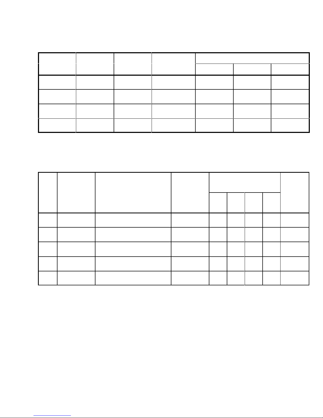
Ordering
The
charts below provide a cross reference between
identification numbers stamped on the parts and the
Graco part number
assemblies available, grouped by basic gun type.
Chart 2 shows fluid nozzle/needle combinations. Chart
3 shows the air caps available.
The following is an example of how to use these
charts:
D Y
our application calls for a
Chart 1
shows this to be a
Chart 1: Gun Combinations Available
P600: Pressure Feed Guns
. Chart 1 shows the complete gun
pressure feed gun
P600 basic gun
.
.
Charts
D
Using
Chart 2
cosity call for an
nation
.
D
By using
is best for the application.
D
This makes your combination a
1
shows that the
nation is
G600:
Gravity Feed Guns
, the flow rate required and fluid vis
02 fluid nozzle and needle
Chart 3
217–601
, you determine that the
Graco part number
.
02 air cap
P600–02–02
for this combi
combi-
.
Chart
-
-
Combinations:
Ordering
Part No.
217–600 P600 0 0
217–601 P600 02 02
S600: Siphon Feed Guns
Ordering
Part No.
217–602 S600 2 2
217–605 S600 3 31
Gun Nozzle
See Chart 2
Combinations:
Gun Nozzle
See Chart 2
See Chart 3
See Chart 3
Terms:
Light Fluid:
enamel primers.
Medium Fluid:
epoxies, vinyls, high flow – high viscosity
19 to 24 seconds (No. 2 Zahn cup). Auto, furniture, appliances, fine-finish metallics, top coats, lacquer
22 to 41 seconds (No. 2 Zahn cup). Contact adhesive, latex, maintenance paints, textures, primers,
.
Air Cap
Air Cap
Combinations:
Ordering
Part No.
217–607 G600
217–609 G600 3 31
Gun Nozzle
See Chart 2
2
Air Cap
See Chart 3
21
,
Heavy Fluid:
4 307-378
Mastics, block fillers, roof coating, sound deadeners, adhesive, textures.
Page 5
Ordering
g
Length
tion
Chart 2: Fluid Nozzle/Needle Combinations*
Type
Orifice Size
Flow Rate
fl. oz./min.
(liters/min.)
Recommended
Usage
(See TERMS)
Charts
Kit Nozzle
Order
Part No.
Only
Needle Only
0
02
2
3
*
Needles and fluid nozzles are manufactured in matched, lapped sets and should be ordered as a kit to ensure
0.032”
(0.8
mm)
0.039”
(1.0 mm)
0.051”
(1.3 mm)
0.059”
(1.5 mm)
4–10
(0.12–0.30)
8–17
(0.24–0.51)
4–8
(0.12–0.24)
6–10
(0.18–0.30)
Light fluid
Pressure feed
Medium fluid
Pressure feed
Light fluid
Siphon feed
Medium fluid
Siphon feed
106–639 106–610 106–622
106–640 106–611 106–623
106–641 106–612 106–624
106–642 106–613 106–625
perfect seating of the needle in the fluid nozzle.
Chart 3: Air Caps Available
Air
Recommended Nozzle
Order
0 02 2 3
Part No.
X 106–600
X 106–601
X 106–602
X 106–603
X 106–605
Type
0
02
2
21
31
Pattern
Len
th
at 8 in.
(200 mm)
4–8”
(100–200
(150–250 mm)
(75–150 mm)
(100–150 mm)
(125–175 mm)
mm)
6–10”
3–6”
4–6”
5–7”
Pattern Shape
Recommended Usage
Blunt
end pattern. Low production,
fine-finish
Slight taper
duction; general purpose.
Blunt end. Small work and
touch-up.
Medium taper
metallics, touch-up and repair
Slight taper
fine-finish, metallics, touch-up.
and touch-up.
. Low to medium pro
, low production,
. Medium production,
Consump-
tion
cfm at psi
(m3/min.
at bar)
8.5 at 50
(0.24 at 3.5)
-
.
8.1 at 50
(0.23 at 3.5)
3 at 40
(0.08 at 2.8)
7 at 40
(0.17 at 2.8)
8 at 40
(0.22 at 2.8)
NOTE:
See page 18 for
Air Flow Charts
.
307-3785
Page 6
Installation
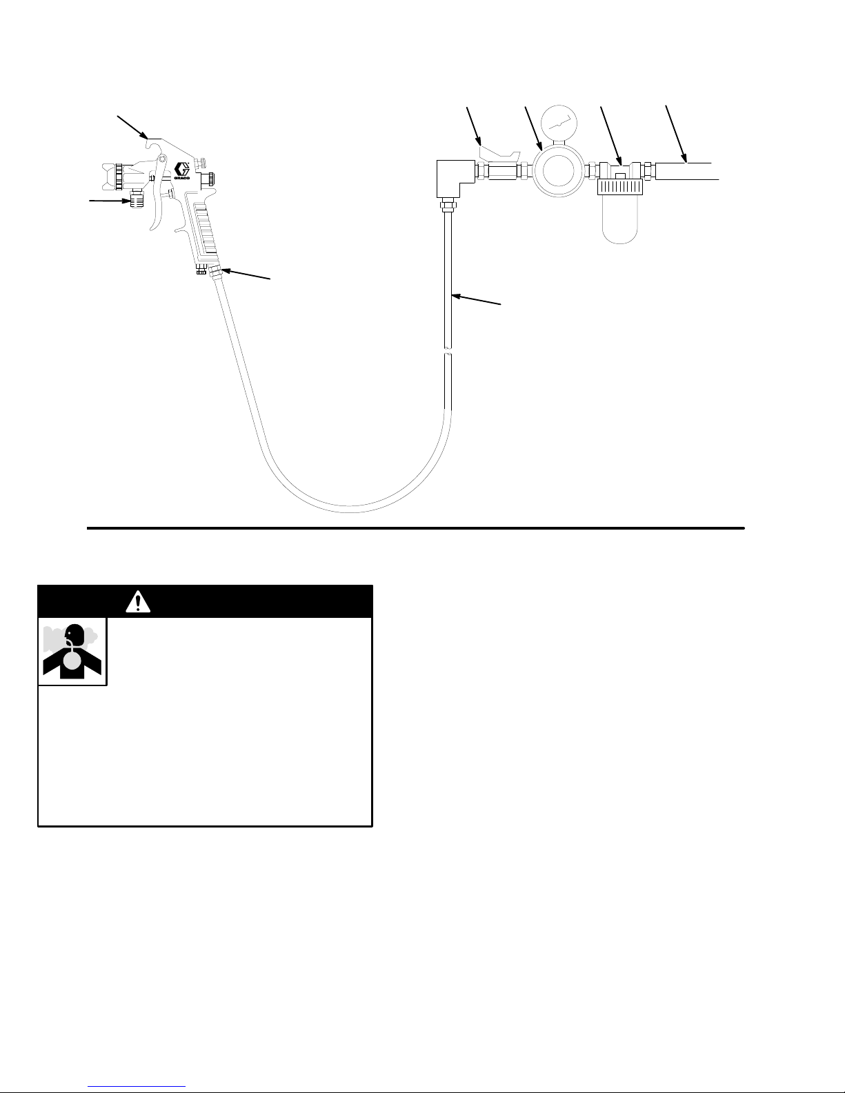
Fig.
1
A
Pressure Feed Model Shown
B
C
D
KEY
EF G H
A Model
B
C
D
E
F
G
H
600 Spray Gun
Fluid Inlet; 1/4 npsm
Air Inlet; 1/4 npsm
Air Hose
Air Shut-of
Air Regulator
Air Filter
Air Supply Line
f V
alve
04835
Ventilate the Spray Booth
WARNING
TOXIC
FLUID HAZARD
T
o prevent hazardous concentrations of
toxic and/or flammable vapors, spray
only in a properly ventilated spray booth.
Never operate the spray gun unless ventilation
fans are operating.
Check and follow all of the national, state and local
codes regarding air exhaust velocity requirements.
Check and follow all local safety and fire codes.
Installation Procedure
NOTE:
installation accessories.
See
Accessories
section for information on
1.
Install an air filter (G) in the gun air supply line to
ensure a clean dry air supply to the gun. See
Fig. 1. Dirt and moisture in the air line can af
fect
the appearance of your finished workpiece.
2.
Install an air regulator (F) downstream from the air
filter to control atomizing air pressure to the gun.
3.
Install an air shut-of
4.
Connect the atomizing air hose (D) to the 1/4
f valve (E).
npsm air inlet (C) of the gun.
5.
Connect the fluid supply hose, siphon cup or grav
ity cup (see Fig. 2 ) to the 1/4 npsm fluid inlet (B)
of the gun.
NOTE:
If you use a fluid supply line, install a fluid regu
lator in the gun fluid supply line to control fluid pressure
to the gun.
-
-
6 307-378
Page 7
Installation
NOTE:
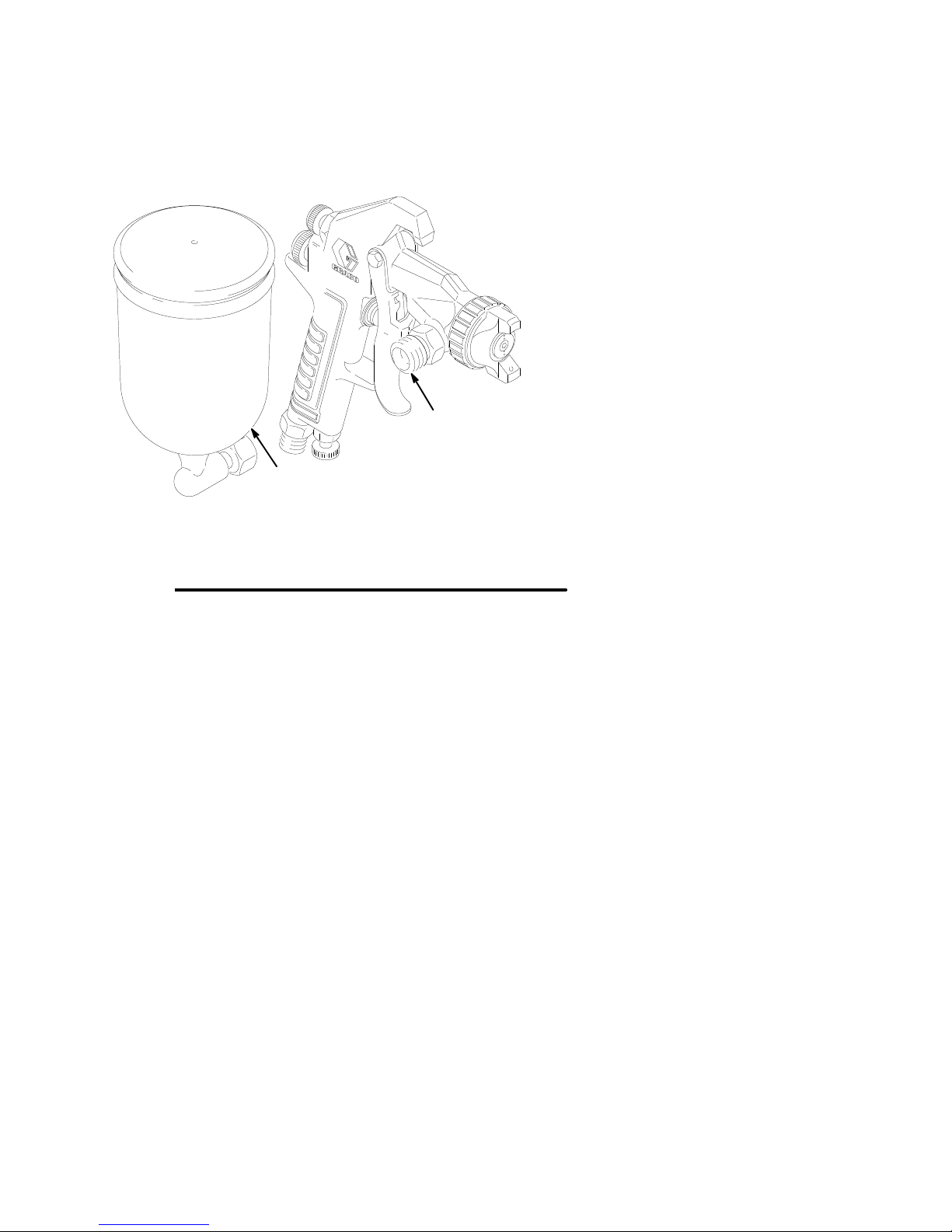
On the gravity gun,
gravity cups connect to
the gun at a fluid inlet on the side of the gun. See
Fig. 2.
A
KEY
A Gravity
B
Cup
Gravity Gun Fluid Inlet 1/4 npsm
Fig. 2
B
04837
Page 8
Operation
Pressure Relief Procedure
WARNING
PRESSURIZED
The system pressure must be manually relieved to
prevent the system from starting or spraying acci
dentally. T
dental spray from the gun, splashing fluid, or mov
ing parts, follow the
whenever you:
D
are instructed to relieve the pressure,
D
stop spraying,
D
check or service any of the system equipment,
D
or install or clean the spray nozzle.
1. T
urn of
f the air and fluid supply to the gun.
2. T
rigger the gun into a grounded metal waste con
tainer to relieve system pressures.
Filter the Fluid
EQUIPMENT HAZARD
o reduce the risk of an injury from acci
Pressure Relief Procedure
NOTE:
way
T
Hold the gun about 8 in. (200 mm) away from the sur
face of the test piece. Adjust the air pressure to the
-
-
-
-
gun until proper atomization is achieved. Use the low
est possible air pressure to obtain the desired results.
NOTE:
regulate air at the gun.
Continuous Spraying
Leave the fan and fluid adjustment valves in the full
open positions. This provides maximum fluid flow and
prevents premature wear on the fluid nozzle. Use
separate regulators to control the air and fluid flow to
the gun.
Short-term Operations
The pattern size and fluid output volume may be re
duced by turning in the fan and fluid adjustment
valves.
If the fluid adjustment knob is turned in all the
, the gun will emit only air
est the Spray Pattern
The air adjustment valve can also be used to
.
-
-
-
Strain
or filter the paint to remove coarse particles and
sediment, then check the viscosity of your paint. Install
the proper needle/nozzle set and air cap combination
selected from the charts on page 5.
Adjusting the Spray Pattern (See Fig. 3)
The
desired pattern, volume of fluid output and degree
of atomization can easily be obtained by regulating the
fan adjustment valve (5) and the fluid adjustment knob
(6).
Adjust the Pattern Size
T
urn the fan adjustment valve (5) out (counterclock
wise) to make the spray pattern wider
Adjust the Fluid Output V
T
urn the fluid adjustment knob (6) out all the way
(counterclockwise). Then adjust the air pressure at the
pressure feed tank until the desired fluid flow is ob
tained. For the final adjustment, turn the fluid adjust
ment knob in (clockwise) to reduce the volume of fluid
output until the desired results are obtained.
olume for Pressure Feed
.
-
-
-
Spray Pattern Direction
WARNING
T
o reduce the risk of serious injury whenever you
are instructed to relieve pressure, always follow the
Pressure Relief Procedure
The direction of the spray pattern is determined by the
position of the air cap (3). The horns of the air cap
should be the opposite direction (horizontal or vertical)
of the desired direction of the spray pattern. T
the spray pattern direction, first
Then loosen and turn the air cap to the desired posi
tion and hand tighten the air cap securely
Proper pattern adjustment will give a spray pattern
shaped like this:
at left.
o change
relieve the pressure
-
.
.
Adjust the Fluid Output V
T
urn the fluid adjustment knob (6) in (clockwise) to re
duce the volume of fluid output, and turn it out (coun
terclockwise) to increase the fluid output.
olume for Siphon Feed
Vertical Pattern
-
-
See
the
Troubleshooting Chart
solution of improper spray patterns.
Horizontal Pattern
for the cause and
Page 9
Maintenance
CAUTION
Methylene Chloride with formic or propionic acid is
not
recommended as a flushing or cleaning sol
vent with this gun or any other device with nylon or
aluminum components, as it can damage these
parts.
CAUTION
T
o avoid contaminating the fluid being sprayed, be
sure that the solvents used are compatible with the
fluid being sprayed.
T
o avoid getting solvent in the gun air passages,
never immerse the gun in solvent.
Cleaning
1. T
o clean the gun, flush it with a compatible solvent
until all traces of paint are removed from the gun
passages.
2.
Relieve the pressure.
3.
Wipe the outside of the gun clean with a solvent
dampened cloth.
-
4.
If the air cap and fluid nozzle need cleaning,
lieve the pressure
from the gun. Remove the fluid nozzle with the
special nozzle wrench (21), supplied. Soak the
fluid nozzle in solvent and wipe it with a clean
cloth. Soak the air cap in solvent and scrub it with
a fine bristled brush. T
cap, use a toothpick or other soft implement to
avoid damaging critical surfaces.
, and remove the air cap (3)
o clean the holes in the air
re-
CAUTION
Never use metal instruments to clean holes in the
air cap and nozzle. Metal instruments can damage
the holes in the air cap and fluid nozzle, resulting in
distortion of the spray pattern.
WARNING
T
o reduce the risk of serious injury whenever you
are instructed to relieve pressure, always follow the
Pressure Relief Procedure
on page 8.
Lubricating
Lubricate the gun daily with light oil at the points
marked
needle spring (7) with lightweight grease or petroleum
jelly.
in Fig. 3. Periodically lubricate the fluid
307-3789
Page 10
Troubleshooting
WARNING
To
reduce the risk of serious injury whenever you
are instructed to relieve pressure, always follow the
Pressure Relief Procedure
on page 8.
1.
Relieve the pressure before you check or service
any system equipment.
2.
Check all possible causes and solutions in the
Troubleshooting Chart
before disassembling the
gun.
NOTE:
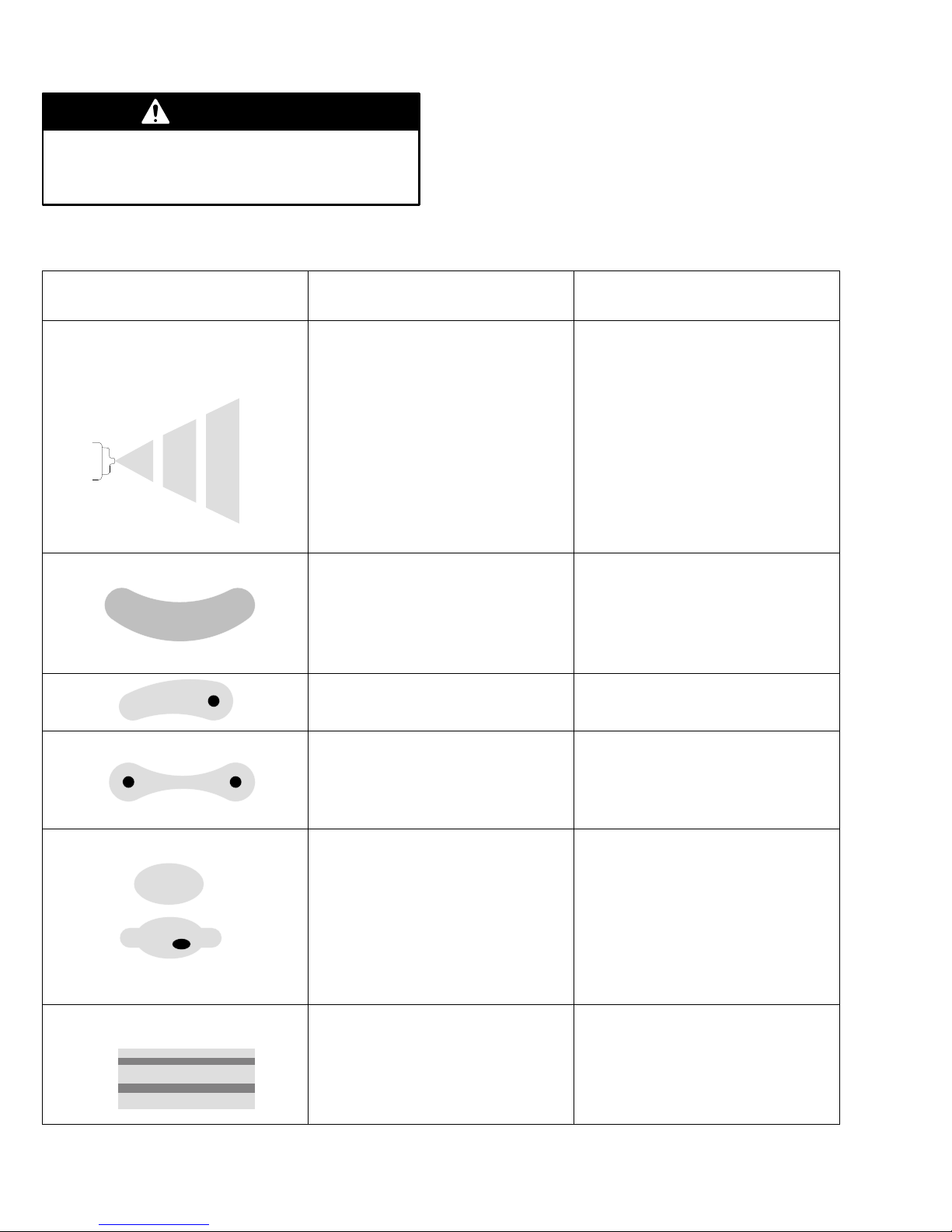
Some improper patterns are caused by the
improper balance between air and fluid.
Problem:
Improper Spray Pattern
Fluttering or spitting spray
Cause Solution
Insufficient
Loose fluid nozzle or damaged fluid
nozzle taper seat.
Dirt between fluid nozzle, taper seat,
and body
Loose or cracked fluid inlet fitting (22).
Loose fluid tube in cup or tank.
Dry or worn fluid needle packing or
loose
fluid passage (siphon feed).
Fluid build-up on air cap; partially
clogged horn holes. Full air pressure
from clean horn hole forces fan pattern
toward clogged end.
Damaged fluid nozzle or air cap holes.
Fluid build-up on the perimeter of fluid
nozzle orifice, or partially clogged fluid
nozzle orifice.
T
oo high atomization air pressure.
fluid supply
.
packing nut permits air to get into
.
Adjust fluid regulator or fill fluid supply
ighten fluid nozzle or replace fluid
T
nozzle and needle.
Clean.
T
ighten or replace fitting.
Tighten.
Lubricate or replace packings (10);
tighten packing nut (9).
Clean
with soft
in
suitable solvent and wipe clean.
Replace damaged part.
Remove
hard
instruments.
Reduce air pressure or adjust air ad
justment valve (17).
implement or submerge
obstruction. Never
use wire or
-
.
Fluid too thin.
Not enough fluid pressure.
Low atomization air pressure.
Fluid too thick.
T
Streaks
Last coat of fluid applied too wet.
T
Insuf
Non-uniform spray pattern.
10 307-378
oo much fluid.
oo much air pressure.
ficient air pressure.
Regulate fluid viscosity
Increase fluid pressure.
Increase air pressure or adjust fan ad
justment valve (5).
Regulate fluid viscosity
On siphon feed guns
by adjusting fluid adjustment knob (6).
On pressure feed guns
pressure. Adjust fluid adjustment knob
(6) until proper pattern is obtained.
Apply drier finish with multiple strokes.
Use lowest air pressure necessary.
Increase air pressure.
Clean or replace air cap.
.
.
, reduce fluid flow
, reduce fluid
-
Page 11

Problem Cause Solution
Fluid
packing nut leaking.
Air leakage from front of gun.
Fluid leakage from front of gun.
Troubleshooting
Loose needle packing nut (9).
W
orn needle packings (10).
Air valve (12, 13) not seating properly
Needle (1) worn or damaged.
W
orn needle and nozzle seat in fluid
nozzle (2).
Needle packings (10) too tight.
. Clean, service.
Tighten.
Replace.
Replace.
Replace fluid nozzle and needle.
Lubricate packings (10) and adjust
packing nut (9).
307-37811
Page 12
Service
4
5
3
5
6
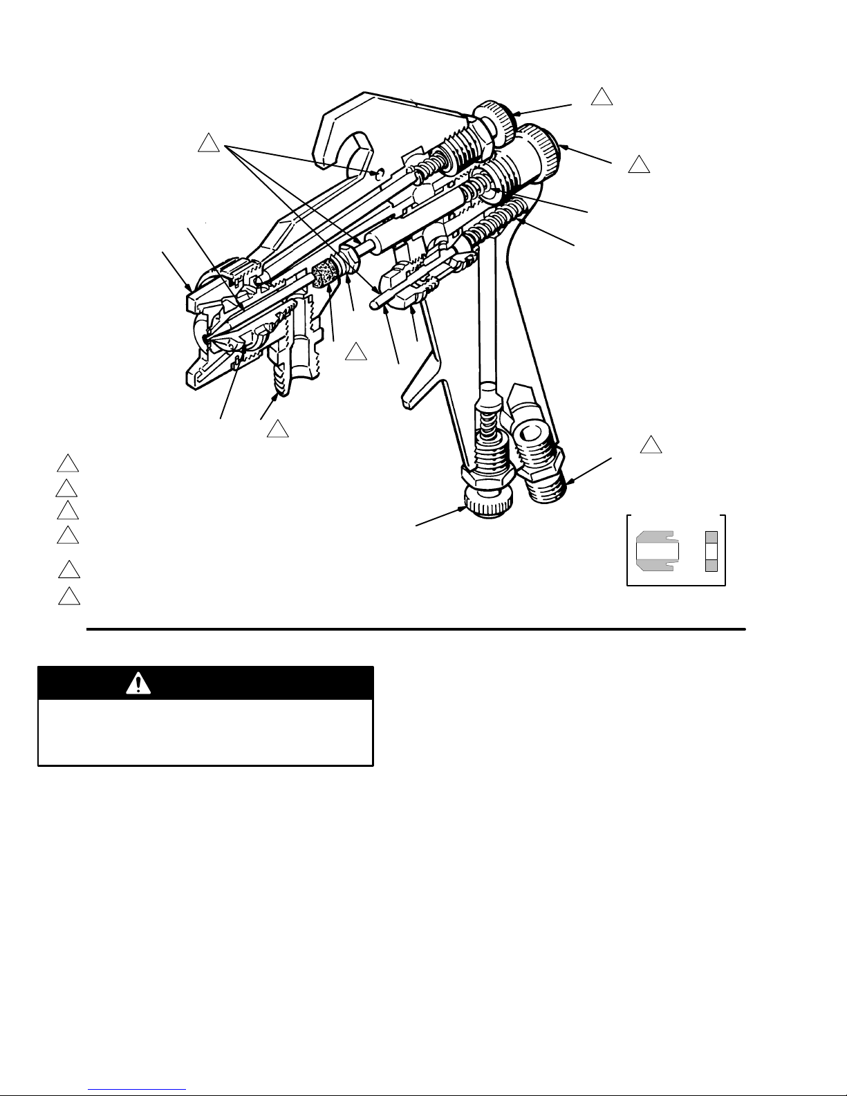
Fig.
1
3
10
22
1
2
Apply
1
2
3
4
5
6
Loctiter 242 sealant or equivalent on
threads and torque to 20 ft-lb (27 N.m).
See Detail D.
Lubricate daily with light oil.
T
urn counterclockwise to widen spray pattern. T
clockwise to narrow spray pattern.
T
urn counterclockwise to increase fluid output.
T
urn clockwise to decrease fluid output.
Apply Loctiter PST pipe sealant or equivalent on threads.
3
9
2
urn
12
17
13
11
7
6
23
DETAIL D
03704
WARNING
To
reduce the risk of serious injury whenever you
are instructed to relieve pressure, always follow the
Pressure Relief Procedure
Relieve pressure
before you check or service any
system equipment.
NOTE:
spring (1
spring (1
The fluid needle spring (7) and the air valve
1) are not interchangeable. The air valve
1) is slightly larger in diameter and will not fit
properly into the fluid valve cavity. See Fig. 3.
12 307-378
on page 8.
Air Valve Service
1. If
there is air leakage at the air valve needle (12),
remove the trigger and unscrew the air valve as
sembly
2.
Clean and inspect the needle (12), spring (1
air valve (13) for wear or damage. Replace if
needed.
3.
Apply a few drops of lightweight machine oil to the
air valve needle (12) and reassemble the air valve.
. See Fig. 3.
-
1) and
Page 13

Fluid Packing Replacement
1. If
leakage occurs at the fluid needle packing nut
(9), tighten the nut. If leakage cannot be stopped
by tightening the packing nut, remove the fluid ad
justing valve knob (6), spring (7) and needle (1).
See Fig. 3.
2.
Unscrew the packing nut (9) and remove the old
packings (10). A small hooked tool can be used to
remove packings from the gun body
inspect all the parts for wear or damage, replacing
parts as needed.
3.
Lubricate the new packings with lightweight oil and
insert them into the gun body in the order shown in
Fig. 3, Detail D.
4.
Install the needle (1), spring (7) and fluid adjust
ment knob (6) into the gun body
nut (9) onto the needle before inserting the needle
into the packing cavity
.
. Clean and
. Slide the packing
Service
5. T
toms out, then back it out six full turns for proper
spring adjustment.
6.
-
-
With the trigger released, screw the packing nut
(9) in until the packing is fully compressed, then
back the nut off until the needle moves freely when
the gun is triggered.
NOTE:
daily as explained in
Installing Fluid and Air Fittings
If
the fluid fitting (22) is removed, be sure to install its
gasket and washer when reinstalling the fitting. Apply
Loctiter
threads and torque it into the gun body to 20 ft-lb
(27 N
If the air fitting (23) is removed, apply Loctiter PST
pipe sealant or equivalent to its threads and screw it
into the gun body
urn the fluid adjustment knob (6) in until it bot
For the best fluid packing life, lubricate the gun
Maintenance.
242 sealant or equivalent on the fluid fitting
Sm).
.
-
307-37813
Page 14
Model 600
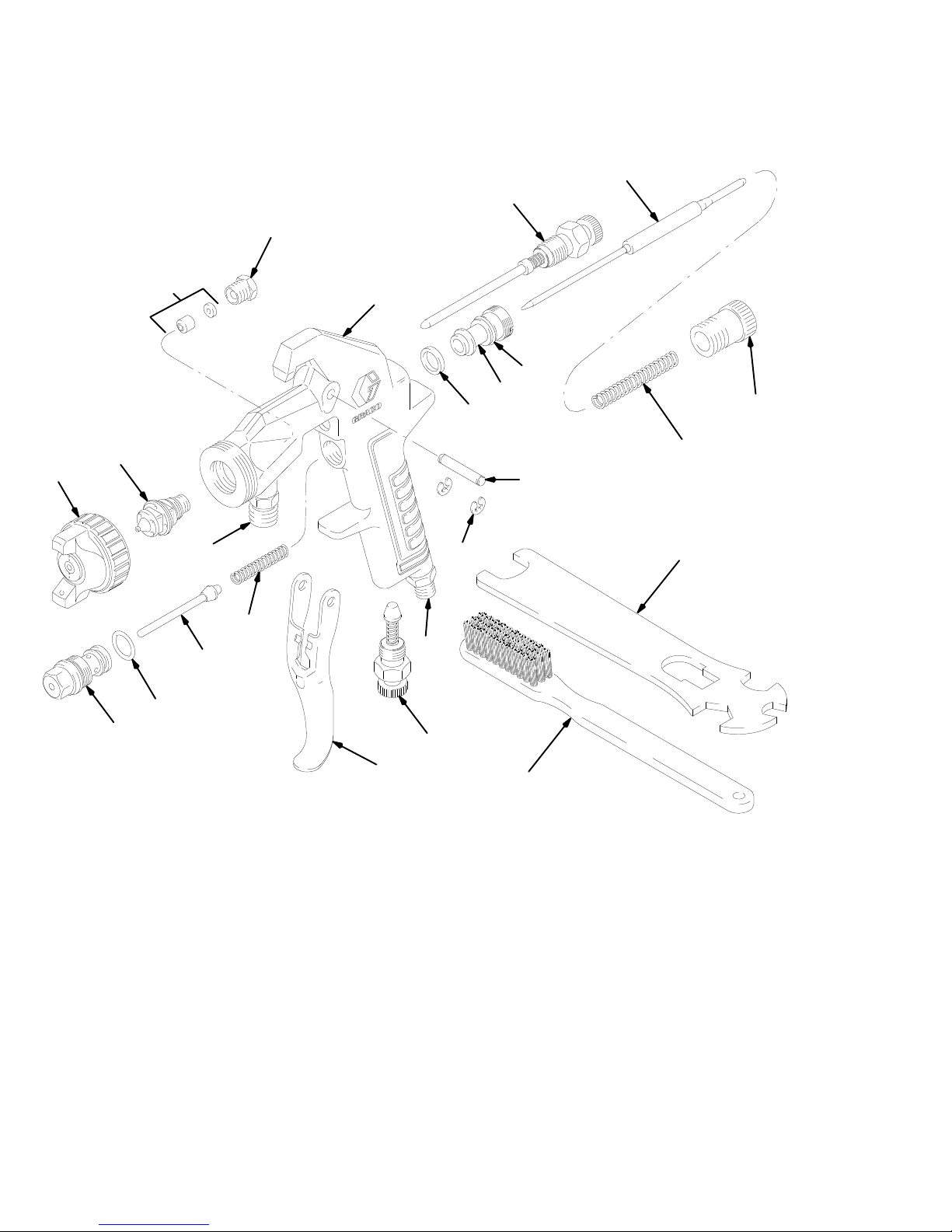
Includes items 1–23
10n
Parts
1
5
9
4
19n
8
18n
6
2
3
22
11
12n
19n
13n
14
Ref
No. Part No. Description Qty.
7
15n
16n
21
23
17n
20
Ref
No. Part No. Description Qty.
1
2
3
4 106–688 BODY
106–638 BODY
5 106–620 VAL
6 105–553
7 105–554
8 106–621
9 106–619 NUT
10n 106–658 KIT
11 106–635 SPRING, compression, air valve 1
12n 106–636 VAL
NEEDLE, fluid; See chart on page 5
NOZZLE, fluid; See chart on page 5
AIR CAP; See chart on page 5
, gun,
siphon/pressure feed only;
Includes items 22 & 23
, gun,
gravity feed only;
Includes item 23
(fluid inlet fitting not sold separately)
VE, fan adjustment
KNOB, fluid adjustment
SPRING, compression, fluid needle
GUIDE, needle, fluid
, packing, needle
, packing, needle
VE, air (needle)
1
13n 106–637 KIT
1
14 106–634 TRIGGER 1
1
15n 106–633
16n 106–632
1
17n 106–631 VAL
18n 105–551 GASKET 1
19n 105–563 O-RING 2
1
20 BRUSH 1
1
21 110–763 WRENCH 1
1
22 106–689
1
1
1
23 106–690
1
1
Keep these spare parts on hand to reduce down time.
n
, packing, air valve
PIN, pivot, trigger
RING, retaining
VE, air adjusting
FITTING, fluid;
only
; includes gasket & washer (not
sold separately)
FITTING, air 1
pressure & siphon feed
1
1
1
1
1
Page 15

Notes
Page 16
Accessories
Use Only Genuine Graco Parts and Accessories
Air
Atomizing Hose, Buna-N
200 psi (14 bar) Maximum Working Pressure
0.312 in. (7.9 mm) ID; coupled 1/4 npsm(f) swivel both
ends; neoprene cover
210–866
210–867
210–868
Throat Seal Liquid (TSL) 206–995
1 quart (0.97 liter) non-evaporation lubricant for air and
fluid packings.
15 ft (4.7 m) long
25 ft (7.6 m) long
50 ft (15.2 m) long
Siphon Cup PC–12 105–701
20.4 oz. (600 cc) capacity; 1/4 npsm(f)
Replacement diaphragm available.
Order part number 106–678.
Replacement lid gasket available.
Gasket is polyethylene.
Order part number 106–680.
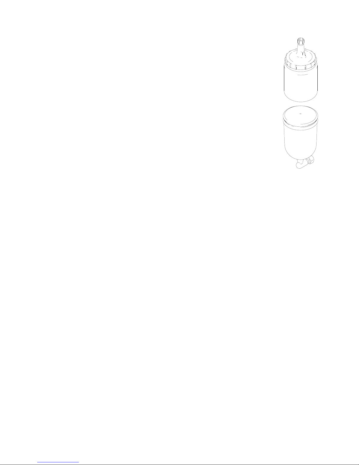
Gravity Cup Lid 1
Replacement lid for Gravity Cup PC–45 105–702.
The
manual was revised to include the following changes:
D
The maximum working pressure was changed to 100 psi.
D
CE symbol was added to the front page.
D T
ext and warnings were updated for CE requirements.
10–750
Manual
Change Summary
Gravity Cup PC–4S 105–702
13.6 oz. (400 cc) capacity; 1/4 npsm(f)
04836
Page 17
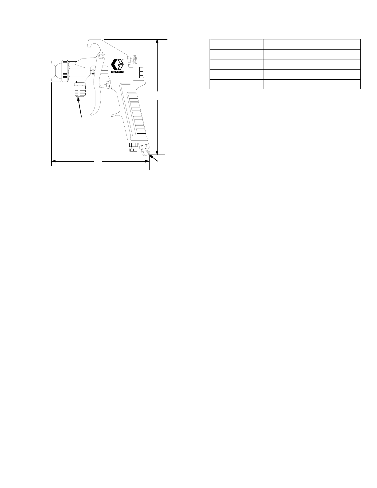
Dimensional
Drawing
Reference
A 5.7 in. (145 mm)
B
C
D
C
B
A
Maximum
Maximum
Weight 17
Wetted
Maxiumum
Noise
Sound pressure
Sound power
working fluid pressure
working air pressure
.
. . . . . . . . . . . . . . . . . . . . . . . . . . . . . . . . . . . . . . . . . . . . . . . . . . . . . . . . . . . . . . . . . . . . . . . . . . . . . . . . . .
parts
data*
.
. . . . . . . . . . . . . . . . . . . . . . . . . . . . . . . . . . . . . . . . . . . . . . . . .
working temperature
.
. . . . . . . . . . . . . . . . . . . . . . . . . . . . . . . . . . . . . . . . . . . . . . . . . . . . . . . . . . . . . . . . . . . . . . . . . . .
.
. . . . . . . . . . . . . . . . . . . . . . . . . . . . . . . . . . . . . . . . . . . . . . . . . . . . . . . . . . . . . . . . . . . . . . . . . . . . .
.
. . . . . . . . . . . . . . . . . . . . . . . . . . . . . . . . . . . . . . . . . . . . . . . . . . . . . . . . . .
.
. . . . . . . . . . . . . . . . . . . . . . . . . . . . . . . . . . . . . . . . . . . . . . . . . . . . . . . . . . .
. . . . . . . . . . . . . . . . . . . . . . . . . . . . . . . . . . . . . . . . . . . . . . . . . . . . . . . . . . .
D
Technical
Data
Brass, polyethylene and polyester elastomer
Dimension
1/4 npsm fluid inlet
6.85 in. (174 mm)
1/4 npsm air inlet
100 psi (7 bar)
100 psi (7 bar)
104_F (40_C).
oz. (475 g)
77.6 Db(A)
89.4 Db(A)
*
All readings were taken with the gun controls fully open with an air inlet pressure of 65 psi (4.5 bar). Sound pres
sure was tested to CAGI-PNUEROP – 1969. Sound power was tested to ISO 3744 – 1981.
-
307-37817
Page 18
Air
Flow Charts
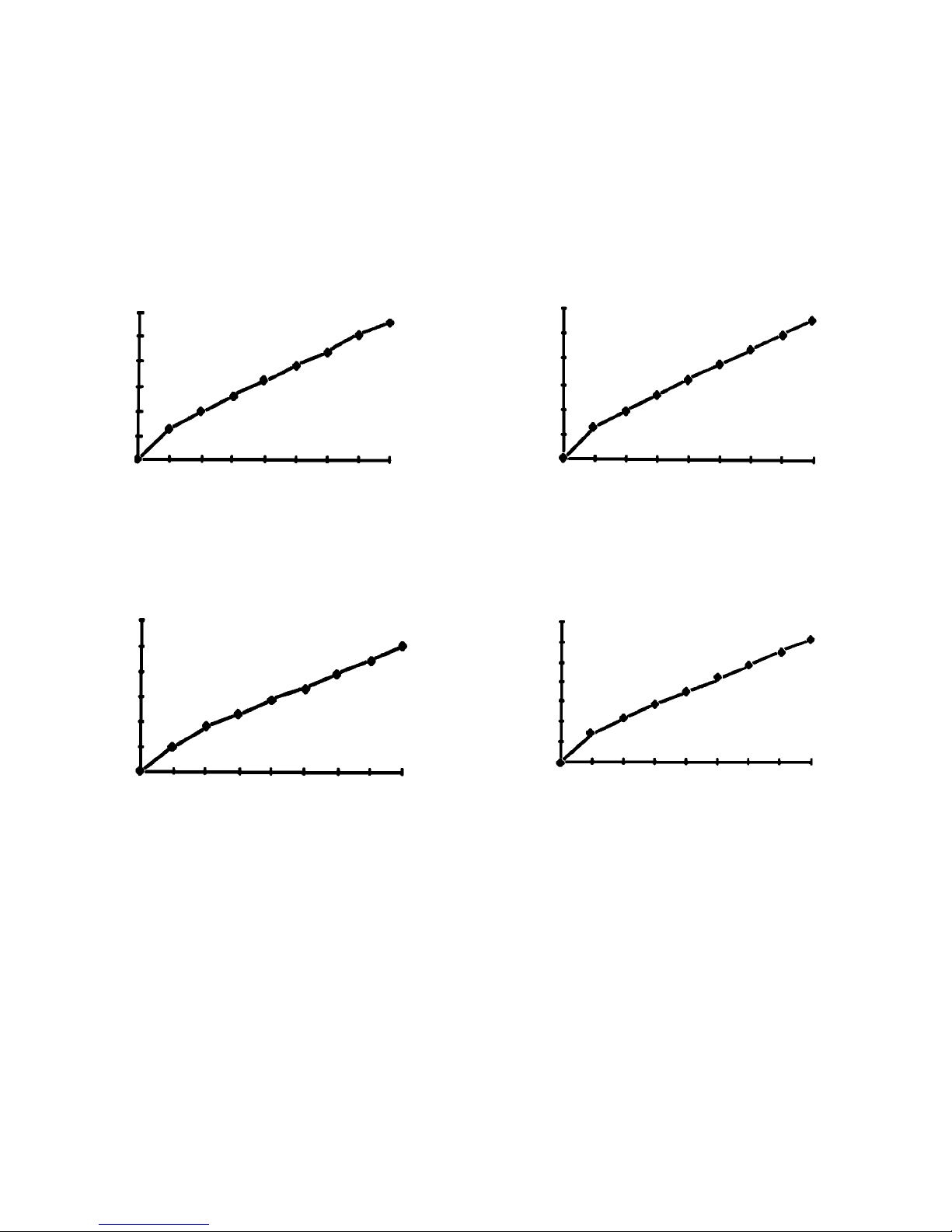
Each chart is headed by a gun model number
. The
first number refers to the 600 gun series. The next
number refers to the fluid nozzle. The last number re
fers to the air cap.
To use the charts:
1. Choose
the chart corresponding to your need.
(Gun Model – Nozzle – Air Cap)
Model 600–0–0
Part No. 217–600
Air Pressure (psig)
Air Flow
(SCFM)
12
10
8
6
4
2
0
0 10203040506070 80
2.
On the horizontal axis, note the air pressure that
will be used.
-
3.
Go up vertically until you intersect the actual air
flow line.
4.
Go across and read the air flow in scfm.
Model 600–02–02
Part No. 217–601
Air Pressure (psig)
Air Flow
(SCFM)
12
10
8
6
4
2
0
01020304050607080
Air Flow
(SCFM)
Model 600–2–2
Part No. 217–602
6
5
4
3
2
1
0
0 1020304050607080
Air Pressure (psig)
Air Flow
(SCFM)
Model 600–3–31
Part No. 217–605
14
12
10
8
6
4
2
0
01020304050607080
Air Pressure (psig)
18 307-378
Page 19

Notes
Page 20

The
WARRANTY
Graco
warrants all equipment manufactured by it and bearing its name to be free from defects in material and workmanship on
the date of sale
warranty,
tive.
ommendations.
Graco will, for a period of twelve months from the date of sale, repair or replace any part of the equipment proven defec
This warranty applies only when the equipment is installed, operated and maintained in accordance with Graco’
Graco Warranty and Disclaimers
by an authorized Graco distributor to the original purchaser for use. As purchaser’s sole remedy for breach of this
-
s written rec-
This warranty does not cover
misapplication, abrasion, corrosion, inadequate or improper maintenance, negligence, accident, tampering, or substitution of
non–Graco component parts. Nor shall Graco be liable for malfunction, damage or wear caused by the incompatibility with Graco
equipment of structures, accessories, equipment or materials not supplied by Graco, or the improper design, manufacture, instal
lation, operation or maintenance of structures, accessories, equipment or materials not supplied by Graco.
This warranty is conditioned upon the prepaid return of the equipment claimed to be defective to an authorized Graco distributor
for verification of the claim. If the claimed defect is verified, Graco will repair or replace free of charge any defective parts. The
equipment will be returned to the original purchaser transportation prepaid. If inspection of the equipment does not disclose any
defect in material or workmanship, repairs will be made at a reasonable charge, which charges may include the costs of parts,
labor and transportation.
DISCLAIMERS AND LIMITATIONS
The terms of this warranty constitute purchaser’s sole and exclusive remedy and are in lieu of any other warranties (express or
implied),
liabilities, including product liabilities, based on negligence or strict liability
tial damages or loss is expressly excluded and denied. In no case shall Graco’
Any action for breach of warranty must be brought within two (2) years of the date of sale.
EQUIPMENT NOT COVERED BY GRACO WARRANTY
Graco makes no warranty
respect to accessories, equipment, materials, or components sold but not manufactured by Graco. These items sold, but not
manufactured by Graco (such as electric motor
Graco will provide purchaser with reasonable assistance in making any claim for breach of these warranties.
including warranty of merchantability or warranty of fitness for a particular purpose
, and Graco shall not be liable for
, and disclaims all implied
warranties of merchantability and fitness for a particular purpose
, switches, hose, etc.) are subject to the warranty
, any malfunction, damage or wear caused by faulty installation,
, and of any non–contractual
. Every form of liability for direct, special or consequen
s liability exceed the amount of the purchase price.
, with
, if any
, of their manufacturer
.
-
-
Graco
TO
PLACE AN ORDER
utor
, or call this number to identify the distributor
closest to you:
1–800–367–4023 T
Foreign Offices:
, contact your Graco distrib
oll Free
Sales
Belgium; Canada; England; Korea; Switzerland; France; Germany; Hong Kong; Japan
Offices:
Phone Numbers
-
Atlanta, Chicago, Detroit, Los Angeles,
FOR TECHNICAL ASSIST
information or assistance regarding the application of
Graco equipment:
1–800–543–0339 T
ANCE,
service repair
oll Free
GRACO INC. P.O. BOX 1441
PRINTED
IN U.S.A.
MINNEAPOLIS, MN
307–378 March 1980, Revised April 1995
55440–1441
 Loading...