

Page 1
Instructions
Parts
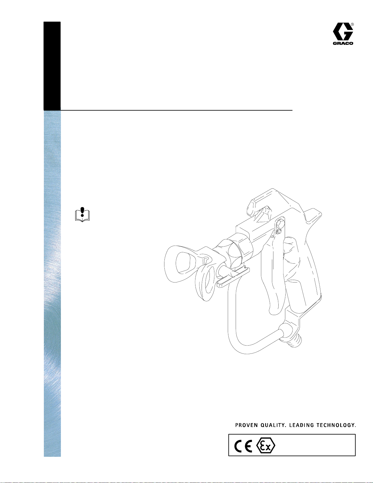
MODEL 510
Airless Spray Gun
7400 psi (50.8 MPa, 510 bar) Maximum Working Pressure
Part No. 236995, Series B
Includes a Heavy-Duty 510 RAC IV Tip Guard and size 619 SwitchTip.
Read warnings and instructions.
See page 2 for Table of Contents.
308438 Rev.F
GRACO INC.ąP.O. BOX 1441ąMINNEAPOLIS, MNą55440-1441
Copyright 1994, Graco Inc. is registered to I.S. EN ISO 9001
03965
II 2 G
Page 2

Table of Contents
Symbols 2. . . . . . . . . . . . . . . . . . . . . . . . . . . . . . . . . . . . . . . . . . . . . . . . . . . . . . . . . . . . . . . . . . . . . . . . . . . . . . . . .
Warnings 3. . . . . . . . . . . . . . . . . . . . . . . . . . . . . . . . . . . . . . . . . . . . . . . . . . . . . . . . . . . . . . . . . . . . . . . . . . . . . . . .
Installation/Operation 6. . . . . . . . . . . . . . . . . . . . . . . . . . . . . . . . . . . . . . . . . . . . . . . . . . . . . . . . . . . . . . . . . . . . . .
System Requirements 6. . . . . . . . . . . . . . . . . . . . . . . . . . . . . . . . . . . . . . . . . . . . . . . . . . . . . . . . . . . . . . . . .
How to Use the Gun Trigger Safety 6. . . . . . . . . . . . . . . . . . . . . . . . . . . . . . . . . . . . . . . . . . . . . . . . . . . . . .
Pressure Relief Procedure 7. . . . . . . . . . . . . . . . . . . . . . . . . . . . . . . . . . . . . . . . . . . . . . . . . . . . . . . . . . . . . .
How to Operate the Gun 8. . . . . . . . . . . . . . . . . . . . . . . . . . . . . . . . . . . . . . . . . . . . . . . . . . . . . . . . . . . . . . .
How to Adjust the Spray Pattern 8. . . . . . . . . . . . . . . . . . . . . . . . . . . . . . . . . . . . . . . . . . . . . . . . . . . . . . . .
Care of the Spray Tip and Tip Guard 9. . . . . . . . . . . . . . . . . . . . . . . . . . . . . . . . . . . . . . . . . . . . . . . . . . . . .
How to Flush the Gun 10. . . . . . . . . . . . . . . . . . . . . . . . . . . . . . . . . . . . . . . . . . . . . . . . . . . . . . . . . . . . . . . . .
How to Check the Gun Diffuser Operation 11. . . . . . . . . . . . . . . . . . . . . . . . . . . . . . . . . . . . . . . . . . . . . . .
Service 12. . . . . . . . . . . . . . . . . . . . . . . . . . . . . . . . . . . . . . . . . . . . . . . . . . . . . . . . . . . . . . . . . . . . . . . . . . . . . . . . .
Parts 16. . . . . . . . . . . . . . . . . . . . . . . . . . . . . . . . . . . . . . . . . . . . . . . . . . . . . . . . . . . . . . . . . . . . . . . . . . . . . . . . . . .
Technical Data 17. . . . . . . . . . . . . . . . . . . . . . . . . . . . . . . . . . . . . . . . . . . . . . . . . . . . . . . . . . . . . . . . . . . . . . . . . .
Dimensions 17. . . . . . . . . . . . . . . . . . . . . . . . . . . . . . . . . . . . . . . . . . . . . . . . . . . . . . . . . . . . . . . . . . . . . . . . . . . . .
Graco Standard Warranty 18. . . . . . . . . . . . . . . . . . . . . . . . . . . . . . . . . . . . . . . . . . . . . . . . . . . . . . . . . . . . . . . . .
Graco Information 18. . . . . . . . . . . . . . . . . . . . . . . . . . . . . . . . . . . . . . . . . . . . . . . . . . . . . . . . . . . . . . . . . . . . . . .
Symbols
Warning Symbol
WARNING
This symbol alerts you to the possibility of serious
injury or death if you do not follow the instructions.
Caution Symbol
CAUTION
This symbol alerts you to the possibility of damage to
or destruction of equipment if you do not follow the
instructions.
3084382
Page 3
WARNING
INJECTION HAZARD
Spray from the gun, hose leaks or ruptured components can inject fluid into your body and cause an
extremely serious injury, including the need for amputation. Splashing fluid in the eyes or on the skin
can also cause serious injury.
D Fluid injected into the skin might look like just a cut, but it is a serious injury. Get immediate medi-
cal attention.
D Do not point the spray gun at anyone or any part of the body.
D Do not put hand or fingers over the spray tip.
D Do not stop or deflect fluid leaks with your hand, body, glove or rag.
D Do not “blow back” fluid; this is not an air spray system.
D Always have the tip guard and the trigger guard on the spray gun when spraying.
D Check the gun diffuser operation weekly.
D Be sure the gun trigger safety operates before spraying.
D Lock the gun trigger safety when you stop spraying.
D Follow the Pressure Relief Procedure on page 7 if the spray tip clogs and whenever you: are
instructed to relieve pressure; stop spraying; clean, check, or service the equipment; and install or
clean the spray tip.
D Tighten all fluid connections before operating the equipment.
D Check the hoses, tubes and couplings daily. Replace worn, damaged, or loose parts immediately.
Permanently coupled hoses cannot be repaired; replace the entire hose.
TOXIC FLUID HAZARD
Hazardous fluids or toxic fumes can cause serious injury or death if splashed in the eyes or on the
skin, swallowed, or inhaled.
D Know the specific hazards of the fluid you are using. Read the fluid manufacturer’s warnings.
D Store hazardous fluid in an approved container. Dispose of hazardous fluid according to all local,
state and national guidelines.
D Wear the appropriate clothing, gloves, eyewear and respirator.
308438 3
Page 4
WARNING
FIRE AND EXPLOSION HAZARD
Improper grounding, poor air ventilation, open flames or sparks can cause a hazardous condition and
result in fire or explosion and serious injury.
D Ground the equipment and the object being sprayed. See Ground the System on page 6.
D If there is any static sparking while using the equipment, stop spraying immediately. Identify and
correct the problem.
D Provide fresh air ventilation to avoid the buildup of flammable vapors from solvent or the fluid being
sprayed.
D Do not smoke in the spray area.
D Extinguish all open flames or pilot lights in the spray area.
D Do not turn on or off any light switch in the spray area while operating or if fumes are present.
D Electrically disconnect all equipment in the spray area.
D Keep the spray area free of debris, including solvent, rags, and gasoline.
D Do not operate a gasoline engine in the spray area.
EQUIPMENT MISUSE HAZARD
INSTRUCTIONS
Equipment misuse can cause the equipment to rupture, malfunction or start unexpectedly and result in
serious injury.
D This equipment is for professional use only.
D Read all instruction manuals, tags, and labels before operating the equipment.
D Use the equipment only for its intended purpose. If you are uncertain about usage, call your Graco
distributor.
D Do not alter or modify this equipment. Use only genuine Graco parts and accessories.
D Check the equipment daily. Repair or replace worn or damaged parts immediately.
D Do not exceed the maximum working pressure of the lowest rated system component. This equip-
ment has a 7400 psi (50.8 MPa, 510 bar) Maximum Working Pressure.
D Use fluids or solvents which are compatible with equipment wetted parts. See the Technical Data
section of all equipment manuals. Read the fluid and solvent manufacturer’s warnings.
D Route the hoses away from the traffic areas, sharp edges, moving parts, and hot surfaces. Do not
expose Graco hoses to temperatures above 180_F (82_C) or below –40_F (–40_C).
D Use only Graco approved hoses. Do not remove hose spring guards, which help protect the hose
from rupture caused by kinks or bends near the couplings.
D Wear hearing protection when operating this equipment.
D Comply with all applicable local, state and national fire, electrical and other safety regulations.
RECOIL HAZARD
Due to the very high fluid pressure, a strong recoil action will occur when you trigger this gun. If you
are unprepared, your hand could be forced back toward your body or you could lose your balance and
fall, resulting in serious injury.
3084384
Page 5

Notes
308438 5
Page 6
Installation/Operation
System Requirements
WARNING
INJECTION HAZARD
Keep the wallet-sized warning card,
provided with this gun, with the operator
at all times. The card contains important
treatment information should an injection injury
occur. Additional cards are available at no charge
from Graco Inc.
WARNING
The equipment must have a bleed-type master air
valve (pneumatic pumps only) and a fluid drain
valve. These accessories help reduce the risk of
serious injury from injection, splashing in the eyes
or on the skin, or moving parts, when adjusting or
repairing the pump or gun.
1. The bleed-type master air valve relieves air
trapped between this valve and the pneumatic
pump after the air regulator is shut off. Trapped air
can cause the pump to cycle unexpectedly.
Ground the System
WARNING
FIRE AND EXPLOSION HAZARD
Improper grounding could cause static
sparking, which could cause a fire or
explosion. To reduce the risk of property
damage or serious injury, ground the
pump and all other equipment used or
located in the spray area. Also read FIRE OR
EXPLOSION HAZARD on page 4.
Check your local electrical code for detailed grounding
instructions for your area and type of equipment. Also
follow the grounding instructions provided in your
pump or sprayer manual. The gun obtains grounding
through connection to a properly grounded fluid hose
and pump or sprayer.
How to Use the Gun Trigger Safety
1. To lock the gun trigger safety, turn the safety to a
right angle with the gun body. See Fig. 1.
2. To unlock the gun trigger safety, push the safety
out and turn it parallel with the gun body. See
Fig. 1.
2. The fluid drain valve assists in relieving fluid pressure in the displacement pump, hose and gun;
triggering the gun to relieve pressure may not be
sufficient.
Gun trigger safety shown locked
1
Gun trigger safety shown unlocked
2
Fig. 1
1
2
03966
3084386
Page 7

Installation/Operation
Pressure Relief Procedure
WARNING
INJECTION HAZARD
The system pressure must be manually
relieved to prevent the system from
starting or spraying accidentally. Fluid
under high pressure can be injected through the
skin and cause serious injury. To reduce the risk of
an injury from injection, splashing fluid, or moving
parts, follow the Pressure Relief Procedure
whenever you:
D are instructed to relieve the pressure,
D stop spraying,
D check or service any of the system equipment,
D or install or clean the spray tip.
1. Lock the gun trigger safety.
2. Shut off the power to the pump. Open the bleedtype master air valve (pneumatic pumps only).
3. Unlock the gun trigger safety.
4. Hold a metal part of the gun firmly to a grounded
metal pail. Trigger the gun to relieve pressure.
5. Lock the gun trigger safety.
6. Open the fluid drain valve, having a container
ready to catch the drainage. Leave the drain valve
open until you are ready to spray again.
7. If you suspect that the spray tip or hose is completely clogged or that pressure has not been fully
relieved, very slowly loosen the tip guard retaining
nut or hose end coupling and relieve pressure
gradually. Clean the tip or hose obstruction.
308438 7
Page 8

Installation/Operation
How to Operate the Gun
WARNING
RECOIL HAZARD
Due to the very high pressure, a strong
recoil action will occur when you trigger
the gun. If you are unprepared, your
hand could be forced back toward your body or you
could lose your balance and fall, resulting in serious injury.
WARNING
INJECTION HAZARD
To reduce the risk of serious injury,
including injection:
D Do not exceed the maximum working pressure
of the gun or the lowest rated component in the
system.
D Follow the Pressure Relief Procedure on page
7 whenever you are instructed to relieve the
pressure.
4. Install the SwitchTip (8) and tip guard (30). Follow
the instructions in the manual, supplied. See
Fig. 2.
5. Start the pump. Trigger the gun onto test paper.
Adjust the fluid pressure until the spray is
completely atomized. Use the lowest pressure
necessary to get the desired results. Higher pressure may not improve the spray pattern and will
cause premature tip and pump wear.
6. If adjusting the pressure does not give a good
spray pattern, relieve pressure and then try
another tip size.
7. Use a full-open, full-close trigger action. Hold the
gun about 14 in. (350 mm) from and at right angles
to the work surface. Don’t swing the gun in an arc.
Practice to find the best length and speed of
stroke.
How to Adjust the Spray Pattern
1. To adjust the spray pattern direction, relieve pressure. Loosen the tip guard retaining nut (B). Turn
the tip guard/tip groove horizontally (C) for a
horizontal pattern and vertically (A) for a vertical
pattern. Tighten the nut. See Fig. 3.
A
8
30
Fig. 2
NOTE: Strain the fluid you are spraying if it contains
particles which could clog the spray tip.
1. Connect a grounded fluid hose (A) to the gun inlet.
See Fig. 2.
2. With no tip installed, start the pump. Flush the
pump according to the instructions supplied with it.
Use the lowest pressure possible. Be sure you
have a firm footing and hold the gun securely.
Prime the system with the material.
03967
2. The spray tip orifice and spray angle determines
the coverage and size of pattern. When more
coverage is needed, use a larger spray tip rather
than increasing fluid pressure.
CAUTION
Openings in the tip guard reduce paint buildup on the
guard while spraying. Damage to the sharp edges of
the openings causes paint to collect at that area.
Never hang the gun by the tip guard.
B
A
C
3. Relieve the pressure.
3084388
Fig. 3
03968
Page 9

Installation/Operation
Care of the Spray Tip and Tip Guard
WARNING
INJECTION HAZARD
To reduce the risk of injection or
splashing in the eyes or on the skin:
D Do not place a hand, body or rag in front of the
spray tip when cleaning or checking a clogged
tip. Point the gun toward the ground or into a
waste container when checking to see if the
spray tip is cleared.
D Do not try to “blow back” paint; this is not an air
spray gun.
D Do not wipe fluid buildup off the gun or spray tip
until pressure is relieved. Follow the Pressure
Relief Procedure on page 7 whenever you
are instructed to relieve the pressure.
Cleaning during the day
If the spray tip clogs while spraying
1. Stop spraying immediately.
2. Lock the gun trigger safety. Rotate the RAC IV tip
handle back 180_. See Fig. 4.
3. Unlock the gun trigger safety. Trigger the gun into
a pail or onto the ground to remove the clog.
4. Lock the gun trigger safety. Rotate the tip handle
to the spraying position. See Fig. 4.
5. If the tip is still clogged, engage the gun trigger
safety, shut off the sprayer and disconnect the
power source, and open the fluid drain valve to
relieve pressure. Clean the spray tip as shown in
manual 307991, supplied with the RAC IV.
CAUTION
Do not soak the entire gun in solvent. Prolonged
exposure to solvent can ruin the packings.
1
Spraying position shown. Turn
handle 180_ and trigger gun to
clear clog.
1. Relieve the pressure.
2. Clean the front of the tip frequently during the day
to help reduce fluid buildup. Also clean the tip and
tip guard at the end of each work day. Use a
solvent-soaked brush to clean the spray tip.
Fig. 4
1
03965
308438 9
Page 10

Installation/Operation
How to Flush the Gun
WARNING
To reduce the risk of serious injury, including
splashing fluid in the eyes or on the skin, or static
electric discharge when flushing:
D Be sure the entire system, including flushing
pails, are properly grounded.
D Remove the tip guard and spray tip.
D Maintain metal to metal contact between the
gun and the flushing pail.
D Use the lowest possible pressure.
Flush the pump and gun before the fluid can dry in it.
If it is available, the flushing procedure provided in your
pump or sprayer manual should be used instead of this
procedure.
1. Relieve the pressure.
2. Remove the tip guard and spray tip. Soak and
clean the parts.
3. Put the pump intake in a grounded pail of compatible solvent.
4. Start the pump at its lowest pressure.
5. Trigger the gun into the original pail. When solvent
appears, release the trigger.
WARNING
INJECTION HAZARD
To reduce the risk of an injection injury,
follow the Pressure Relief Procedure
on page 7 whenever you are instructed
to relieve the pressure.
6. Now trigger the gun into the solvent pail. Circulate
the fluid until the system is thoroughly flushed.
7. Relieve the pressure.
30843810
Page 11

Installation/Operation
How to Check the Gun Diffuser Operation
The Standard Needle and Seat Kit, 237398, has the
number 090 stamped on the needle and seat. The seat
does have a diffuser.
The optional Non-diffused Needle and Seat Kit,
237260, has the number 125 stamped on the needle
and seat. The seat does not have a diffuser.
WARNING
INJECTION HAZARD
The diffuser, located in the valve seat,
creates an irregular spray pattern when
the gun is sprayed without a tip guard,
such as during cleaning. The irregular spray pattern helps reduce the risk of an injection injury.
If you are using the optional Kit 237260, you must
take extra precautions to keep your hands and
body away from the nozzle of the gun.
Always have the tip guard in place during regular
spraying operations.
Check the diffuser operation weekly. The gun diffuser/
seat (2a) breaks up spray and reduces the risk of
injection when the tip is not installed. Perform the test
below. If it fails, replace the entire Needle and Seat Kit.
Diffuser/seats and needles are not sold separately;
using old parts with new ones will result in leakage.
1. Relieve the pressure.
2. Remove the tip guard and spray tip.
3. Start the sprayer and adjust it to the lowest
pressure.
4. Aim the gun into a grounded metal pail while
holding it firmly to the pail. Trigger the gun. If the
fluid emitted is not diffused into an irregular
stream, replace the entire needle kit immediately.
See Fig. 5.
Irregular spray pattern
1
WARNING
INJECTION HAZARD
To reduce the risk of an injection injury,
follow the Pressure Relief Procedure
on page 7 whenever you are instructed
to relieve the pressure.
2a
1
Fig. 5
308438 11
Page 12

Service
WARNING
INJECTION HAZARD
To reduce the risk of an injection injury,
follow the Pressure Relief Procedure
on page 7 before checking or servicing
the gun and whenever you are instructed to relieve
the pressure.
2b
2a
Repair Notes
The needle and seat are available only as a kit which
includes items 2a to 2e.
The Standard Needle and Seat Kit, 237398, has the
number 090 stamped on the needle and seat.
A Non-diffused Needle and Seat Kit, 237260, has the
number 125 stamped on the needle and seat. It is
recommended only for use with mastics, sealers and
other high viscosity materials which have fillers that
cannot pass through the standard seat’s diffuser.
Use high quality, general purpose grease where
grease is indicated.
Disassembly
NOTE: If replacing only the needle and seat, Step 5 is
not required.
1. Relieve the pressure.
21
Fig. 7
3. Unscrew the valve seat (2a). Remove the gasket
(2b). See Fig. 7.
28
18
25
Fig. 8
4. Remove one e-clip (27). Push out the pin (18).
Remove the screw (29), pivot pin (28), and trigger
(25). See Fig. 8.
03969
29
27
03970
30
Fig. 6
2. Disconnect the fluid hose (A). Remove the tip
guard (30). Unscrew the spring screw (21) about
1/4 in. (7 mm) to release spring tension.
See Fig. 6.
30843812
A
03967
Fig. 9
5. Remove the screws (24). See Fig. 9.
24
03971
Page 13

22
Service
1
2c
2d
2e
15
Fig. 10
03972
6. Loosen the setscrew (15). Pull the fluid housing (22)
away from the gun body (1). See Fig. 10.
16
17
Fig. 12
03974
8. Remove the needle (2c). Unscrew the seal retainer
(2d). Remove the seal (2e). See Fig. 12.
Cleaning
Clean all parts and cavities thoroughly with a compatible solvent. Dry with a rag or compressed air. Replace
any parts that are worn or damage.
Reassembly
Torque to 20–25 ft-lb (27–34 NSm)
1
2
Lips of seal must face into housing
3
Grease inner cavity of housing
2d
1
2
2e
22
3
Fig. 11
03973
7. While supporting the spring guide (16) to prevent
bending the needle, loosen the setscrews (17).
Remove the spring guide (16). See Fig. 11.
Fig. 13
03975
1. Lightly grease the inner cavities of the fluid housing (22). Install the small seal (2e) so the lips face
into the fluid housing cavity. Install the seal retainer
(2d) and torque to 20–25 ft-lb (27–34 NSm). See
Fig. 13.
308438 13
Page 14

Service
2c
22
Fig. 14
03676
2. Lightly grease the small end of the needle (2c) and
then guide it into the large end of the fluid housing
(22).
Grease the threads
1
Torque to 20–25 ft-lb
2
(27–34 NSm)
2a
2b
22
Fig. 15
03977
Grease this side
1
19
20
1
1
Fig. 17
03979
5. If the spring (19) was removed, grease the spring
adjuster (20) and place it on the spring. Drop this
assembly into the gun body (1). See Fig. 17.
Torque to 30–40 in-lb
1
(3.4–4.5 NSm)
After tightening setscrew (15),
2
fill cavity with petroleum jelly
1
22
3. Place the gasket (2b) on the valve seat (2a).
Grease the threads of the valve seat (2a). Screw
the valve seat into the fluid housing (22). Torque to
20–25 ft-lb (27–34 NSm). See Fig. 15.
1
Seat against needle stem
Apply light strength Loctitet; Torque
2
alternately and evenly to 10–15 in-lb
(1.1–1.7 NSm)
After tightening set-
3
screws (17), fill cavity
with petroleum jelly
Fig. 16
16
17
1
3
2
03978
4. Install the spring guide (16) and seat it against the
needle. Loosely thread both setscrews (17) into the
spring guide, then alternately and evenly tighten the
setscrews to 10–15 in-lb (1.1–1.6 NSm). Fill the setscrew cavities with petroleum jelly.
15
1
Fig. 18
03972
6. Push the fluid housing (22) onto the gun body (1)
until fully seated. Tighten the setscrew (15) to
30–40 in-lb (3.4–4.5 NSm). Fill the setscrew cavity
with petroleum jelly. See Fig. 18.
2
30843814
Page 15

Service
Turn in until screw
1
stops
21
1
Fig. 19
7. Install the screws (24). See Fig. 19.
28
18
25
Fig. 20
24
A
B,16
29
27
03970
03971
Fig. 21
03980
9. If it was removed, install the spring tension screw
(21) at the rear of the gun. Then, turn the screw in
until it stops. See Fig. 21.
Test the Gun Before Regular Use
1. Lock the gun trigger safety. Connect a hose to the
gun. Start and prime the pump.
2. Release the gun trigger safety. Trigger the gun into
a waste container. Release the trigger to be sure
the gun immediately stops spraying and that there
are no leaks.
3. If the gun has a diffuser, check the diffuser using
the procedure on page 11.
4. Install the tip guard before regular use. See
Fig. 22.
8. Position the trigger (25) on the gun body. Insert the
pivot pin (28) into the top hole (A) and secure with
the screw (29) on the other side. Place an e-clip
(27) on one end of the trigger pin (18). Slide the
pin through lower trigger holes and through the
hole (B) in the spring guide (16) (turn the spring
guide to align, as needed). Install the other e-clip
(27). See Fig. 20.
Fig. 22
03965
308438 15
Page 16

Part No. 236995, Series B
Model 510 Airless Spray Gun
Parts
30
2a
2b
2c
28
15
27
18
2d
2e
22
8
16
20
19
17
24
21
29
1
27
25
03964
Ref.
No. Part No. Description Qty.
1 237502 GUN BODY 1
2 237398 NEEDLE AND SEAT KIT
includes items 2a–2e (parts not
sold separately) stamped with the
number 085 [fluid orifice size is
0.085 (2.2 mm)] 1
2a . VALVE SEAT 1
2b . GASKET 1
2c . NEEDLE 1
2d . SEAL RETAINER 1
2e . SEAL 1
8 GHD619 SwitchTip, size 619 1
15 102207 SETSCREW, 1/4–20 1
16 189960 SPRING GUIDE 1
17 112729 SETSCREW, socket head 2
18 189958 TRIGGER PIN 1
19 112727 SPRING 1
20 189990 SPRING ADJUSTER 1
21 110637 ADJUSTING SCREW 1
22 237694 FLUID HOUSING 1
24 107091 SCREW, 1/4–20 2
25 189974 GUN TRIGGER 1
Ref.
No. Part No. Description Qty.
27 112410 E-CLIP 2
28 187965 PIVOT PIN 1
29 203953 SCREW, hex washer head, 10–24 1
30 237162 HEAVY DUTY 510 RAC
TIP GUARD 1
34Y 187346 WARNING SHEET (not shown) 1
35Y 222385 WARNING CARD (not shown) 1
Y Replacement Danger and Warning labels, tags and
cards are available at no cost.
Optional Non-Diffused
Needle and Seat Kit 237260
Use in place of Ref. No. 2, above.
Stamped with the number 125
[fluid orifice size is 0.125 in. (3.2 mm)]
Recommended only for use with mastics, sealers and
other high viscosity materials which have fillers that
cannot pass through the standard seat’s diffuser.
30843816
Page 17

Technical Data
Maximum working pressure 7400 psi. . . . . . . . . . . . . . . . . . . . . . . . . . . . . . . . . . . . . . . . . . . . . . . . . . . . . . . . . . . . .
(50.8 MPa, 510 bar)
Fluid orifice size 0.090 in. (2.3 mm). . . . . . . . . . . . . . . . . . . . . . . . . . . . . . . . . . . . . . . . . . . . . . . . . . . . . . . . . . . . . .
Inlet size 1/4 npsm (m). . . . . . . . . . . . . . . . . . . . . . . . . . . . . . . . . . . . . . . . . . . . . . . . . . . . . . . . . . . . . . . . . . . . . . . . . .
Fluid tube inside diameter 0.245” (6.2 mm). . . . . . . . . . . . . . . . . . . . . . . . . . . . . . . . . . . . . . . . . . . . . . . . . . . . . . . .
Maximum fluid temperature 65.5_C (150_F). . . . . . . . . . . . . . . . . . . . . . . . . . . . . . . . . . . . . . . . . . . . . . . . . . . . . . .
Sound pressure 103 dB(A)*. . . . . . . . . . . . . . . . . . . . . . . . . . . . . . . . . . . . . . . . . . . . . . . . . . . . . . . . . . . . . . . . . . . . .
Sound power 111.6 dB(A)*. . . . . . . . . . . . . . . . . . . . . . . . . . . . . . . . . . . . . . . . . . . . . . . . . . . . . . . . . . . . . . . . . . . . . . .
Wetted parts Tungsten carbide, 17–4 PH passivated stainless . . . . . . . . . . . . . . . . . . . . . . . . . . . . . . . . . . . . . . .
steel, polypropylene, polyethylene
* Results are maximum readings taken at 6000 psi (41 MPa, 414 bar), with HD427 tip, using water. Sound power
level was tested to ISO 3744–1981.
Dimensions
Weight includes tip and tip guard 25.7 oz. (729 gr). . . . . . . . . . . . . . . . . . . . . . . . . . . . . . . . . . . . . . . . . . . . . . . . . . . . . . .
Length 8.25 in. (210 mm). . . . . . . . . . . . . . . . . . . . . . . . . . . . . . . . . . . . . . . . . . . . . . . . . . . . . . . . . . . . . . . . . . . . . . .
Height 8.0 in. (203 mm). . . . . . . . . . . . . . . . . . . . . . . . . . . . . . . . . . . . . . . . . . . . . . . . . . . . . . . . . . . . . . . . . . . . . . . . .
308438 17
Page 18

Graco Standard Warranty
Graco warrants all equipment manufactured by Graco and bearing its name to be free from defects in material and workmanship on the
date of sale to the original purchaser for use. With the exception of any special, extended, or limited warranty published by Graco,
Graco will, for a period of twelve months from the date of sale, repair or replace any part of the equipment determined by Graco to be
defective. This warranty applies only when the equipment is installed, operated and maintained in accordance with Graco’s written
recommendations.
This warranty does not cover, and Graco shall not be liable for general wear and tear, or any malfunction, damage or wear caused by
faulty installation, misapplication, abrasion, corrosion, inadequate or improper maintenance, negligence, accident, tampering, or substitution of non–Graco component parts. Nor shall Graco be liable for malfunction, damage or wear caused by the incompatibility of
Graco equipment with structures, accessories, equipment or materials not supplied by Graco, or the improper design, manufacture,
installation, operation or maintenance of structures, accessories, equipment or materials not supplied by Graco.
This warranty is conditioned upon the prepaid return of the equipment claimed to be defective to an authorized Graco distributor for
verification of the claimed defect. If the claimed defect is verified, Graco will repair or replace free of charge any defective parts. The
equipment will be returned to the original purchaser transportation prepaid. If inspection of the equipment does not disclose any defect
in material or workmanship, repairs will be made at a reasonable charge, which charges may include the costs of parts, labor, and
transportation.
THIS WARRANTY IS EXCLUSIVE, AND IS IN LIEU OF ANY OTHER WARRANTIES, EXPRESS OR IMPLIED, INCLUDING BUT
NOT LIMITED TO WARRANTY OF MERCHANTABILITY OR WARRANTY OF FITNESS FOR A PARTICULAR PURPOSE.
Graco’s sole obligation and buyer’s sole remedy for any breach of warranty shall be as set forth above. The buyer agrees that no other
remedy (including, but not limited to, incidental or consequential damages for lost profits, lost sales, injury to person or property, or any
other incidental or consequential loss) shall be available. Any action for breach of warranty must be brought within two (2) years of the
date of sale.
Graco makes no warranty, and disclaims all implied warranties of merchantability and fitness for a particular purpose in connection
with accessories, equipment, materials or components sold but not manufactured by Graco. These items sold, but not manufactured
by Graco (such as electric motors, switches, hose, etc.), are subject to the warranty, if any, of their manufacturer. Graco will provide
purchaser with reasonable assistance in making any claim for breach of these warranties.
In no event will Graco be liable for indirect, incidental, special or consequential damages resulting from Graco supplying equipment
hereunder, or the furnishing, performance, or use of any products or other goods sold hereto, whether due to a breach of contract,
breach of warranty, the negligence of Graco, or otherwise.
FOR GRACO CANADA CUSTOMERS
The parties acknowledge that they have required that the present document, as well as all documents, notices and legal proceedings
entered into, given or instituted pursuant hereto or relating directly or indirectly hereto, be drawn up in English. Les parties reconnaissent avoir convenu que la rédaction du présente document sera en Anglais, ainsi que tous documents, avis et procédures judiciaires
exécutés, donnés ou intentés à la suite de ou en rapport, directement ou indirectement, avec les procedures concernées.
Graco Information
TO PLACE AN ORDER, contact your Graco distributor, or call one of the following numbers
to identify the distributor closest to you:
1–800–367–4023 Toll Free
612–623–6921
612–378–3505 Fax
All written and visual data contained in this document reflects the latest product information available at the time of publication.
Graco reserves the right to make changes at any time without notice.
International Offices: Belgium, Korea, Hong Kong, Japan
Sales Offices: Minneapolis, Detroit
www.graco.com
PRINTED IN USA 308438 09/1994, Revised 12/2003
30843818
 Loading...