

Page 1
Instructions–Parts List
CARBON STEEL
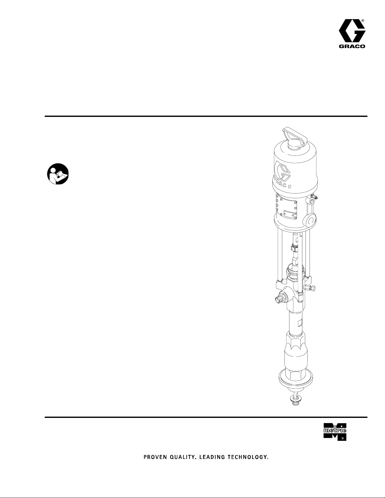
Check–Matet450 Pumps
WITH PRIMING PISTON, AND
SEVERE–DUTY ROD AND CYLINDER
U.S. Patent Nos. 5,147,188 and 5,154,532.
Important Safety Instructions
Read all warnings and instructions in this manual.
Save these instructions.
Table of Contents
List of Models 2. . . . . . . . . . . . . . . . . . . . . . . . . . . . . . . . . .
Symbols 3. . . . . . . . . . . . . . . . . . . . . . . . . . . . . . . . . . . . . .
Warnings 3. . . . . . . . . . . . . . . . . . . . . . . . . . . . . . . . . . . . . .
Installation 6. . . . . . . . . . . . . . . . . . . . . . . . . . . . . . . . . . . . .
Operation 9. . . . . . . . . . . . . . . . . . . . . . . . . . . . . . . . . . . . .
Service
Troubleshooting 12. . . . . . . . . . . . . . . . . . . . . . . . . . . .
Required Tools 14. . . . . . . . . . . . . . . . . . . . . . . . . . . . .
Disconnecting the Displacement Pump 14. . . . . . . .
Reconnecting the Displacement Pump 15. . . . . . . .
Displacement Pump Service 16. . . . . . . . . . . . . . . . .
Parts 23. . . . . . . . . . . . . . . . . . . . . . . . . . . . . . . . . . . . . . . .
Technical Data and Performance Charts 33. . . . . . . . . .
Dimensions 46. . . . . . . . . . . . . . . . . . . . . . . . . . . . . . . . . . .
Mounting Hole Layout 47. . . . . . . . . . . . . . . . . . . . . . . . . .
Warranty 48. . . . . . . . . . . . . . . . . . . . . . . . . . . . . . . . . . . . .
Graco Information 48. . . . . . . . . . . . . . . . . . . . . . . . . . . . .
Model 222768 Shown
308017W
0423A
Page 2

List of Models
Maximum Air
Working Pressure
Model No. Description MPa bar psi MPa bar psi
222770 10:1 ratio Monarkr Pump, Series A
(UHMWPE/PTFE Packed)
235626 10:1 ratio Monarkr Pump, Series A
(PTFE Packed)
222768 20:1 ratio Presidentr Pump, Series A
(UHMWPE/PTFE Packed)
237207 20:1 ratio stubby Presidentr Pump,
Series A (UHMWPE/PTFE Packed)
246933 20:1 ratio Presidentr Pump, Series A
(Tuffstack Throat Packed)
222769 34:1 ratio Senatorr Pump, Series A
(UHMWPE/PTFE Packed)
224660 34:1 ratio Quiet Senatorr Pump,
Series A (UHMWPE/PTFE Packed)
237492 34:1 ratio stubby Senatorr Pump,
Series A (UHMWPE/PTFE Packed)
237780 34:1 ratio stubby Quiet Senatorr
Pump, Series A
(UHMWPE/PTFE Packed)
222778 55:1 ratio Bulldogr Pump, Series A
(UHMWPE/PTFE Packed)
222813 55:1 ratio Quiet Bulldogr Pump,
Series A (UHMWPE/PTFE Packed)
237208 55:1 ratio stubby Bulldogr Pump,
Series A (UHMWPE/PTFE Packed)
237779 55:1 ratio stubby Quiet Bulldogr
Pump, Series A
(UHMWPE/PTFE Packed)
1.2 12 180 12 124 1800
1.2 12 180 12 124 1800
1.2 12 180 25 248 3600
1.2 12 180 25 248 3600
1.2 12 180 25 248 3600
0.8 8 120 28 281 4080
0.8 8 120 28 281 4080
0.8 8 120 28 281 4080
0.8 8 120 28 281 4080
0.6 6.2 90 34 341 4950
0.6 6.2 90 34 341 4950
0.6 6.2 90 34 341 4950
0.6 6.2 90 34 341 4950
Maximum Fluid
Working Pressure
2 308017
Page 3
Symbols
Warning Symbol
WARNING
This symbol alerts you to the possibility of serious
injury or death if you do not follow the instructions.
WARNING
EQUIPMENT MISUSE HAZARD
Equipment misuse can cause the equipment to rupture or malfunction and result in serious injury.
INSTRUCTIONS
D This equipment is for professional use only.
D Read all instruction manuals, tags, and labels before operating the equipment.
D Use the equipment only for its intended purpose. If you are uncertain about usage, call your Graco
distributor.
D Do not alter or modify this equipment. Use only genuine Graco parts and accessories.
Caution Symbol
CAUTION
This symbol alerts you to the possibility of damage to
or destruction of equipment if you do not follow the
instructions.
D Check equipment daily. Repair or replace worn or damaged parts immediately.
D Do not exceed the maximum working pressure stated on the equipment or in the Technical Data
for your equipment. Do not exceed the maximum working pressure of the lowest rated component
in your system.
D Use fluids and solvents which are compatible with the equipment wetted parts. Refer to the Tech-
nical Data section of all equipment manuals. Read the fluid and solvent manufacturer’s warnings.
D Do not use hoses to pull equipment.
D Route hoses away from traffic areas, sharp edges, moving parts, and hot surfaces. Do not expose
Graco hoses to temperatures above 82_C (180_F) or below –40_C (–40_F).
D Wear hearing protection when operating this equipment.
D Comply with all applicable local, state, and national fire, electrical, and safety regulations.
308017 3
Page 4
WARNING
SKIN INJECTION HAZARD
Spray from the spray gun/dispense valve, hose leaks or ruptured components can inject fluid into your
body and cause extremely serious injury, including the need for amputation. Fluid splashed in the eyes
or on the skin can also cause serious injury.
D Fluid injected into the skin might look like just a cut, but it is a serious injury. Get immediate
surgical treatment.
D Do not point the gun/valve at anyone or at any part of the body.
D Do not put your hand or fingers over the spray tip/nozzle.
D Do not stop or deflect leaks with your hand, body, glove or rag.
D Do not “blow back” fluid; this is not an air spray system.
D Always have the tip guard and the trigger guard on the spray gun when spraying.
D Check the gun diffuser operation weekly. Refer to the gun manual.
D Be sure the gun/valve trigger safety operates before spraying/dispensing.
D Lock the gun/valve trigger safety when you stop spraying/dispensing.
D Follow the Pressure Relief Procedure on page 9 whenever you: are instructed to relieve pres-
sure; stop spraying/dispensing; clean, check, or service the equipment; and install or clean the
spray tip/nozzle.
D Tighten all fluid connections before operating the equipment.
D Check the hoses, tubes, and couplings daily. Replace worn, damaged, or loose parts immediately.
Permanently coupled hoses cannot be repaired; replace the entire hose.
D Use only Graco approved hoses. Do not remove any spring guard that is used to help protect the
hose from rupture caused by kinks or bends near the couplings.
MOVING PARTS HAZARD
Moving parts, such as the priming piston, can pinch or amputate your fingers.
D Keep clear of all moving parts when starting or operating the pump.
D Keep hands and fingers away from the priming piston during operation and whenever the pump is
charged with air.
D Before servicing the equipment, follow the Pressure Relief Procedure on page 9 to prevent the
equipment from starting unexpectedly.
4 308017
Page 5
WARNING
FIRE AND EXPLOSION HAZARD
Improper grounding, poor ventilation, open flames or sparks can cause a hazardous condition and
result in a fire or explosion and serious injury.
D Ground the equipment and the object being sprayed. Refer to Grounding on page 8.
D If there is any static sparking or you feel an electric shock while using this equipment, stop spray-
ing/dispensing immediately. Do not use the equipment until you identify and correct the problem.
D Provide fresh air ventilation to avoid the buildup of flammable fumes from solvents or the fluid
being sprayed/dispensed.
D Keep the spray/dispense area free of debris, including solvent, rags, and gasoline.
D Electrically disconnect all equipment in the spray/dispense area.
D Extinguish all open flames or pilot lights in the spray/dispense area.
D Do not smoke in the spray/dispense area.
D Do not turn on or off any light switch in the spray/dispense area while operating or if fumes are
present.
D Do not operate a gasoline engine in the spray/dispense area.
TOXIC FLUID HAZARD
Hazardous fluid or toxic fumes can cause serious injury or death if splashed in the eyes or on the skin,
inhaled, or swallowed.
D Know the specific hazards of the fluid you are using.
D Store hazardous fluid in an approved container. Dispose of hazardous fluid according to all local,
state and national guidelines.
D Always wear protective eyewear, gloves, clothing and respirator as recommended by the fluid and
solvent manufacturer.
308017 5
Page 6

Installation
General Information
NOTE: Reference numbers and letters in parentheses
in the text refer to the callouts in the figures and the
parts drawings.
NOTE: Always use Genuine Graco Parts and Accessories, available from your Graco distributor. Refer to
the Product Data Sheet, Form No. 305546. If you
supply your own accessories, be sure they are adequately sized and pressure-rated to meet the system’s
requirements.
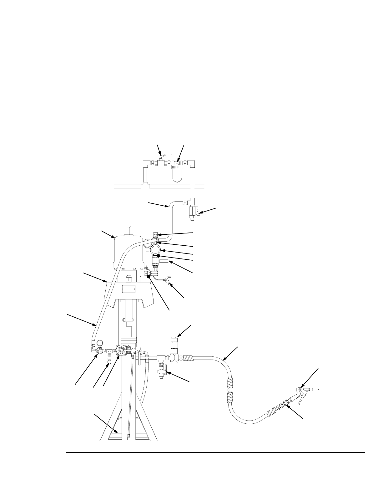
Fig. 1 is only a guide for selecting and installing system components and accessories. Contact your Graco
distributor for assistance in designing a system to suit
your particular needs.
System Accessories
WARNING
A red-handled main air bleed valve (V), pump air
bleed valve (G), and fluid drain valve (L) are required. These accessories help reduce the risk of
serious injury, including fluid injection and splashing
of fluid in the eyes or on the skin, and injury from
moving parts if you are adjusting or repairing the
pump.
The red-handled main air bleed valve (V) shuts off
and relieves the air to the pump and ram. Order
Part No. 113269 for Monark and President Pumps,
or 113218 for Senator and Bulldog Pumps. The
ram will hold pressure if the ram director valve (U)
is in the horizontal (neutral) position. To relieve air
pressure in the ram, close the red-handled bleed
valve (V) and move the director valve (U) to
DOWN. The ram will slowly drop.
The pump air bleed valve (G) relieves air trapped
between it and the pump after the air is shut off.
Trapped air can cause the pump to cycle unexpectedly. Locate the valve close to the pump.
The fluid drain valve (L) assists in relieving fluid
pressure in the displacement pump, hose, and gun.
Triggering the gun to relieve pressure may not be
sufficient. Order Part No. 210658 (3/8 npt).
Air Line
Install the following accessories as shown in Fig. 1,
using adapters as necessary:
D A red-handled main air bleed valve (V) is re-
quired in your system to shut off the air supply to
the pump and ram (see the WARNING at left).
When closed, the valve will bleed off all air in the
ram and pump, and the ram will slowly drop. Be
sure the valve is easily accessible from the pump,
and is located upstream from the air manifold (D).
D The pump air bleed valve (G) is required in your
system to relieve air trapped between it and the air
motor when the valve is closed (see the WARNING
at left). Be sure the valve is easily accessible from
the pump, and is located downstream from the air
regulator (H).
D The pump air regulator (H) controls pump speed
and outlet pressure by adjusting the air pressure to
the pump. Locate the regulator close to the pump,
but upstream from the pump air bleed valve (G).
D An air line lubricator (F) provides automatic air
motor lubrication.
D A pump runaway valve (E) senses when the
pump is running too fast and automatically shuts off
the air to the motor. A pump which runs too fast can
be seriously damaged.
D An air manifold (D) has a swivel air inlet. It has
ports for connecting lines to air accessories, such
as the ram air regulator (T), which controls the air
pressure to the ram.
D The air pressure relief valve (Q) limits the air
pressure to the ram to 10 bar (150 psi).
D The ram director valve (U) controls the raising
and lowering of the ram.
D An air line filter (J) removes harmful dirt and
moisture from the compressed air supply. Also,
install a drain valve (W) at the bottom of each air
line drop, to drain off moisture.
D A bleed-type air valve (K) isolates the air line
accessories for servicing. Locate upstream from all
other air line accessories.
6 308017
Page 7
Installation
Fluid Line Accessories
Install the following accessories in the positions shown
in Fig. 1, using adapters as necessary:
D Install a fluid drain valve (L) in a tee near the
pump fluid outlet. The drain valve is required in your
system to relieve fluid pressure in the displacement
pump, hose and gun/valve (see the WARNING on
page 6). Install with the drain valve pointing down,
but so the handle points up when the valve is open.
D A fluid regulator (M) controls fluid pressure to the
gun/valve, and dampens pressure surges.
JK
S
A
B
Y
S
F
M
D A gun or dispense valve (N) dispenses the fluid.
The gun shown in Fig. 1 is a high pressure dispensing gun for highly viscous fluids.
D A gun/valve swivel (P) allows freer gun/valve
movement.
Air and Fluid Hoses
Be sure all air hoses (S) and fluid hoses (R) are properly sized and pressure-rated for your system. Use
only electrically conductive hoses. Fluid hoses must
have spring guards on both ends.
KEY
A Pump
B 19 Liter (5 Gallon) Air-Powered Ram
C Wiper Plate
D Air Manifold
W
V
D
H
E
G
E Pump Runaway Valve (location shown)
F Air Line Lubricator (location shown)
G Pump Bleed-Type Air Valve
(required, for pump)
H Pump Air Regulator
J Air Line Filter
K Bleed-Type Air Valve (for accessories)
L Fluid Drain Valve (required)
M Fluid Pressure Regulator
N Airless Spray Gun or Dispensing Valve
P Gun/Valve Swivel
Q Ram Air Pressure Relief Valve
R Electrically Conductive Fluid Supply Hose
S Electrically Conductive Air Supply Hose
T Ram Air Regulator
U Ram Director Valve
V Red-Handled Main Air Bleed Valve
W Air LIne Drain Valve
Y Ground Wire (required, see page 8 for
installation instructions)
Fig. 1
T
R
N
L
QU
C
P
05683
308017 7
Page 8
Installation
Grounding
WARNING
FIRE AND EXPLOSION HAZARD
Before operating the pump, ground the
system as explained below. Also read
the section FIRE AND EXPLOSION
HAZARD on page 5.
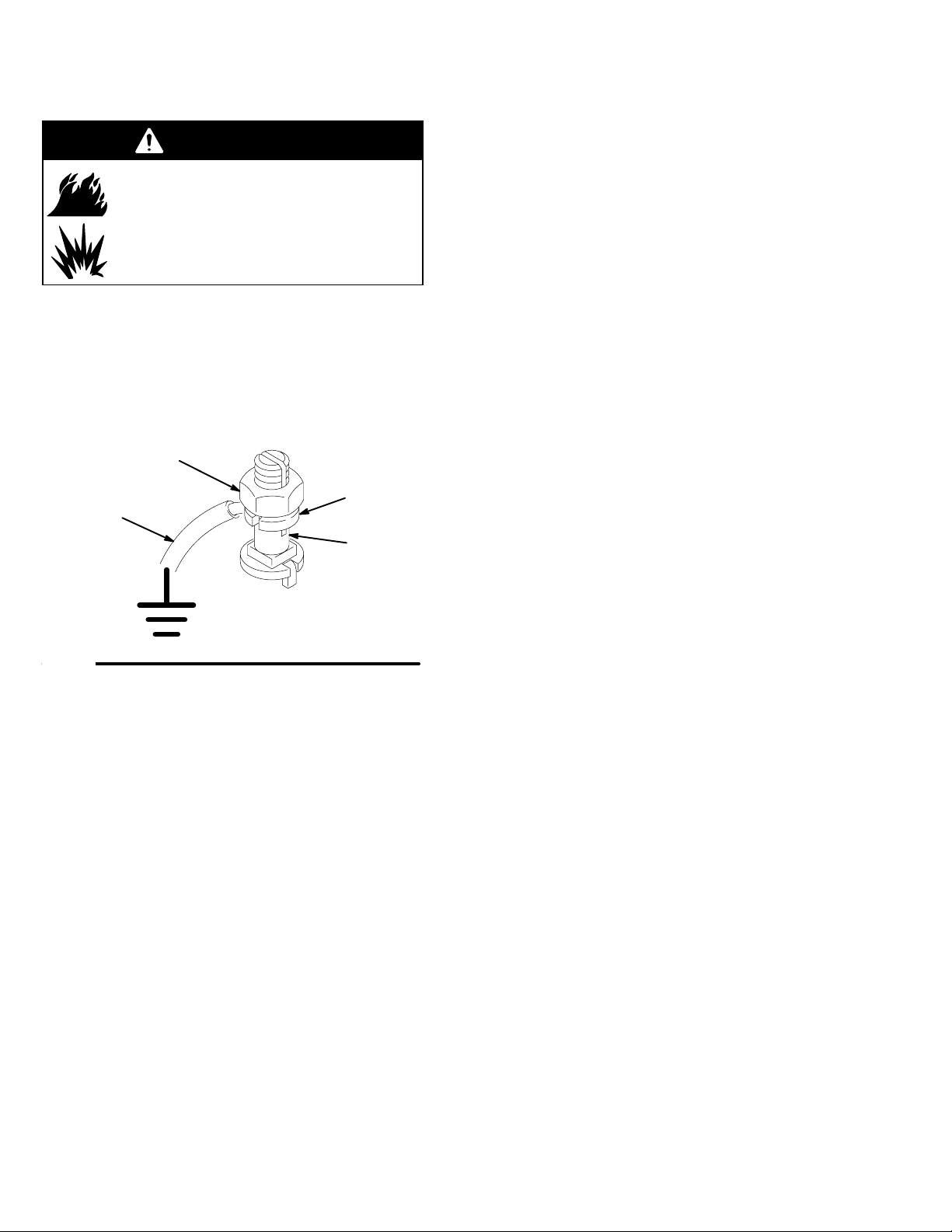
1. Pump: use a ground wire and clamp. See Fig. 2.
Loosen the grounding lug locknut (W) and washer
(X). Insert one end of a 1.5 mm@ (12 ga) minimum
ground wire (Y) into the slot in lug (Z) and tighten
the locknut securely. Connect the other end of the
wire to a true earth ground. Order Part No. 237569
Ground Wire and Clamp.
W
X
Y
Z
0864
Fig. 2
2. Air and fluid hoses: use only electrically conductive
hoses.
3. Air compressor: follow manufacturer’s recommendations.
4. Spray gun/dispense valve: ground through connection to a properly grounded fluid hose and pump.
5. Fluid supply container: follow your local code.
6. Object being sprayed: follow your local code.
7. All solvent pails used when flushing: follow your
local code. Use only metal pails, which are conductive, placed on a grounded surface. Do not
place the pail on a nonconductive surface, such as
paper or cardboard, which interrupts the grounding
continuity.
8. To maintain grounding continuity when flushing or
relieving pressure, always hold a metal part of the
gun/valve firmly to the side of a grounded metal
pail, then trigger the gun/valve.
Mounting Accessories
Mount the pump (A) to suit the type of installation
planned. Pump dimensions and the mounting hole
layout are shown on pages 46 and 47.
If you are mounting the pump on a ram (B), refer to the
manual supplied with the ram for installation and
operation instructions. The ram shown in Fig. 1 is a 19
liter (5 gal.) pail ram, used with a wiper plate (C). The
ram shown includes an air regulator (T). It also requires an air supply hose (S) and an air manifold (D),
which divides the main air supply into separate lines
for the pump and the ram.
By using Pump Mounting Kit 222776, you can also
mount the pump on Floor Stand 222780, 200 liter (55
gal.) Ram 207279, or Inductor 222635.
8 308017
Page 9
Operation
Pressure Relief Procedure
WARNING
SKIN INJECTION HAZARD
The system pressure must be manually
relieved to prevent the system from
starting or dispensing accidentally. Fluid
under high pressure can be injected through the
skin and cause serious injury. To reduce the risk of
an injury from injection, splashing fluid, or moving
parts, follow the Pressure Relief Procedure
whenever you:
D are instructed to relieve the pressure,
D stop spraying/dispensing,
D check or service any of the system equipment,
D or install or clean the spray tip/nozzle.
1. Lock the gun/valve trigger safety.
2. Close the pump’s bleed-type air valve (G, required
in your system).
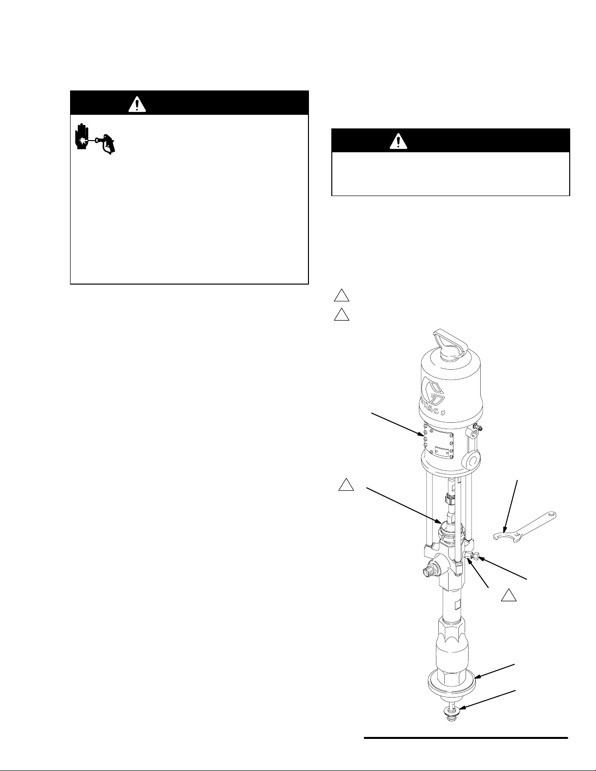
Packing Nut/Wet-Cup
Before starting, fill the packing nut (2) 1/3 full with
Graco Throat Seal Liquid (TSL) or compatible solvent.
See Fig. 3.
WARNING
To reduce the risk of serious injury whenever you
are instructed to relieve pressure, always follow the
Pressure Relief Procedure at left.
The packing nut is torqued at the factory and is ready
for operation. If it becomes loose and there is leaking
from the throat packings, relieve pressure, then torque
the nut to 45–53 NSm (33–39 ft-lb) using the supplied
wrench (110). Do this whenever necessary. Do not
overtighten the packing nut.
1
Bleed hole must face down.
2
Torque to 45–53 NSm (33–39 ft-lb).
3. Shut off the red-handled main air bleed valve (V,
required in your system). If the pump is mounted
on a ram, set the ram director valve (U) to DOWN.
The ram will slowly drop.
4. Unlock the gun/valve trigger safety.
5. Hold a metal part of the gun/valve firmly to the side
of a grounded metal pail, and trigger the gun/valve
to relieve pressure.
6. Lock the gun/valve trigger safety.
7. Open the drain valve (required in your system),
having a container ready to catch the drainage.
8. Leave the drain valve open until you are ready to
spray/dispense again.
AA
110
2
2
35
43
1
23
If you suspect that the spray tip/nozzle or hose is
completely clogged, or that pressure has not been fully
relieved after following the steps above, very slowly
loosen the tip guard retaining nut or hose end coupling
and relieve pressure gradually, then loosen completely.
Now clear the tip/nozzle or hose.
25
0423A
Fig. 3
308017 9
Page 10
Operation
Flush the Pump Before First Use
The pump is tested with lightweight oil, which is left in
to protect the pump parts. If the fluid you are using
may be contaminated by the oil, flush it out with a
compatible solvent. See Flushing on page 11.
Starting and Adjusting the Pump
WARNING
MOVING PARTS HAZARD
See Fig. 3. The priming piston (25) and
the air motor piston (located behind the
air motor plates, AA) move during operation.
Keep hands and fingers away from the priming
piston (25) during operation and whenever the
pump is charged with air. The priming piston extends beyond the intake cylinder (23) to pull material into the pump and can amputate a hand or finger
caught between it and the intake cylinder. Follow
the Pressure Relief Procedure on page 9,
before checking, clearing, or cleaning the priming
piston.
Never operate the pump with the air motor plates
(AA) removed.
1. Do not install the spray tip yet.
6. Slowly open the air regulator (H) until the pump
starts.
7. Cycle the pump slowly until all air is pushed out
and the pump and hoses are fully primed.
8. Release the gun/valve trigger and lock the trigger
safety. The pump should stall against pressure.
WARNING
SKIN INJECTION HAZARD
To reduce the risk of fluid injection, do not use
your hand or fingers to cover the bleed hole on the
underside of the bleeder valve body (43) when
priming the pump. Use a crescent wrench to open
and close the bleeder plug (35). Keep your hands
away from the bleed hole.
9. If the pump fails to prime properly, open the
bleeder valve plug (35) slightly. Use the bleed hole
on the underside of the valve body (43) as a
priming valve until the fluid appears at the hole.
See Fig. 3. Close the plug (35).
NOTE: When changing fluid containers with the hose
and gun/valve already primed, open the bleeder valve
plug (35) to help prime the pump and vent air before it
enters the hose. Close the plug when all air is eliminated.
2. Supply fluid to the pump, per the requirements of
your system.
3. See Fig. 1. Close the pump air regulator (H).
4. Open the red-handled main air bleed valve (V) and
the pump’s bleed-type air valve (G).
5. Hold a metal part of the gun/valve (N) firmly to the
side of a grounded metal pail and hold the trigger
open.
CAUTION
Do not allow the pump to run dry. It will quickly
accelerate to a high speed, causing damage. If your
pump is running too fast, stop it immediately and
check the fluid supply. If the container is empty and
air has been pumped into the lines, refill the container and prime the pump and the lines, or flush and
leave it filled with a compatible solvent. Eliminate all
air from the fluid system.
10 308017
Page 11
Operation
Starting and Adjusting the Pump
(continued)
10. With the pump and lines primed, and with adequate air pressure and volume supplied, the pump
will start and stop as you open and close the
gun/valve. In a circulating system, the pump will
speed up or slow down on demand, until the air
supply is shut off.
WARNING
To reduce the risk of serious injury whenever you
are instructed to relieve pressure, always follow the
Pressure Relief Procedure on page 9.
11. Relieve the pressure. Install the spray tip in the
gun.
WARNING
COMPONENT RUPTURE HAZARD
To reduce the risk of overpressurizing
your system, which could cause component rupture and serious injury, never
exceed the Maximum Incoming Air Pressure to the
pump (see the Technical Data on pages 33–43).
Flushing
WARNING
FIRE AND EXPLOSION HAZARD
Before operating the pump, read the
section FIRE AND EXPLOSION HAZ-
ARD on page 5. Be sure the entire
system and flushing pails are properly
grounded. Refer to Grounding on page
8.
Flush with a fluid that is compatible with the fluid you
are pumping and with the wetted parts in your system.
Check with your fluid manufacturer or supplier for
recommended flushing fluids and flushing frequency.
Always flush the pump before fluid dries on the displacement rod.
CAUTION
Never leave water or water-base fluid in the pump
overnight. If you are pumping water-base fluid, flush
with water first, then with a rust inhibitor such as
mineral spirits. Relieve the pressure, but leave the
rust inhibitor in the pump to protect the parts from
corrosion.
12. Use the air regulator (H) to control the pump speed
and the fluid pressure. Always use the lowest air
pressure necessary to get the desired results.
Higher pressures cause premature tip/nozzle and
pump wear.
Shutdown and Care of the Pump
WARNING
To reduce the risk of serious injury whenever you
are instructed to relieve pressure, always follow the
Pressure Relief Procedure on page 9.
For overnight shutdown, stop the pump at the bottom
of the stroke to prevent fluid from drying on the exposed displacement rod and damaging the throat
packings. Relieve the pressure.
Always flush the pump before the fluid dries on the
displacement rod. Refer to Flushing at right.
WARNING
To reduce the risk of serious injury whenever you
are instructed to relieve pressure, always follow the
Pressure Relief Procedure on page 9.
1. Relieve the pressure.
2. Remove the spray tip/nozzle from the gun/valve.
3. Hold a metal part of the gun/valve firmly to the side
of a grounded metal pail.
4. Start the pump. Always use the lowest possible
fluid pressure when flushing.
5. Trigger the gun/valve.
6. Flush the system until clear solvent flows from the
gun/valve.
7. Relieve the pressure.
308017 11
Page 12
Troubleshooting
WARNING
To reduce the risk of serious injury whenever you
are instructed to relieve pressure, always follow the
Pressure Relief Procedure on page 9.
1. Relieve the pressure.
2. Check all possible problems and causes before
disassembling the pump.
PROBLEM
Pump fails to operate. Restricted line or inadequate air supply;
Pump operates, but
output is low on both
strokes.
Pump operates, but
output is low on downstroke.
Pump operates, but
output is low on upstroke.
CAUSE SOLUTION
closed or clogged valves.
Obstructed fluid hose or gun/valve;
fluid hose ID is too small.
Fluid dried on the displacement rod. Clean; always stop the pump at the bottom of its
Dirty, worn, or damaged motor parts. Clean or repair; see the separate motor manual.
Restricted line or inadequate air supply;
closed or clogged valves.
Obstructed fluid hose or gun/valve;
fluid hose ID is too small.
Bleeder valve is open. Close the valve.
Air is leaking into the supply container. Check the ram plate seal.
Fluid is too heavy for pump priming. Use the bleeder valve (see page 10); use a ram.
Held open or worn intake valve or seals. Clear the valve; replace the seals.
Worn packings in the displacement
pump.
Fluid too heavy for pump priming. Use the bleeder valve (see page 10); use a ram.
Held open or worn intake valve or seals. Clear the valve; replace the seals.
Held open or worn piston valve or seals. Clear the valve; replace the seals.
Clear; increase the air supply.
Check that all valves are open.
Open, clear*; use a hose with a larger ID.
stroke; keep the wet-cup 1/3 filled with a compatible solvent.
Clear; increase the air supply.
Check that all valves are open.
Open, clear*; use a hose with a larger ID.
Replace the packings.
THE TROUBLESHOOTING CHART IS CONTINUED ON PAGE 13.
* To determine if the fluid hose or gun is obstructed, follow the Pressure Relief Procedure on page 9. Disconnect
the fluid hose and place a container at the pump fluid outlet to catch any fluid. Turn on the air just enough to start
the pump. If the pump starts when the air is turned on, the obstruction is in the fluid hose or gun.
12 308017
Page 13

Troubleshooting
PROBLEM CAUSE SOLUTION
Erratic or accelerated
pump speed.
Exhausted fluid supply. Refill and prime.
Fluid is too heavy for pump priming. Use the bleeder valve (see page 10); use a ram.
Held open or worn piston valve or seals. Clear the valve; replace the seals.
Held open or worn priming piston. Clear; service.
Worn packings in the displacement
pump.
Replace the packings.
308017 13
Page 14

Service
Required Tools
D Torque wrench
D Bench vise, with soft jaws
D Rubber mallet
D Hammer
D O-ring pick
D 13 mm (1/2 in.) dia. brass rod
D Set of socket wrenches
D Set of adjustable wrenches
D Pipe wrench
D Packing nut wrench (110, supplied)
D Thread lubricant
D Thread sealant
Disconnecting the Displacement Pump
1. Flush the pump, if possible. Stop the pump at the
bottom of its stroke.
WARNING
2. Relieve the pressure.
3. Disconnect the air hose. Hold the fluid outlet fitting
(8) with a wrench to keep it from being loosened
while you disconnect the fluid hose.
4. Remove the pump from its mounting. Disconnect
the displacement pump (107) from the motor (101)
as follows. Be sure to note the relative position of
the pump’s fluid outlet (8) to the motor air inlet
(CC).
5. Using an adjustable wrench (or a hammer and
rod), unscrew the coupling nut (104) from the
connecting rod (103) or air motor shaft. Do not
lose or drop the coupling collars (105). See Fig. 4.
6. Hold the tie rod flats with a wrench to keep the
rods from turning. Use the wrench (110) provided
with the pump to unscrew the nuts (106) from the
tie rods (102). Carefully remove the displacement
pump (107) from the motor (101).
To reduce the risk of serious injury whenever you
are instructed to relieve pressure, always follow the
Pressure Relief Procedure on page 9.
7. Refer to page 16 for displacement pump service.
To service the air motor, refer to the separate
motor manual, supplied.
14 308017
Page 15
Service
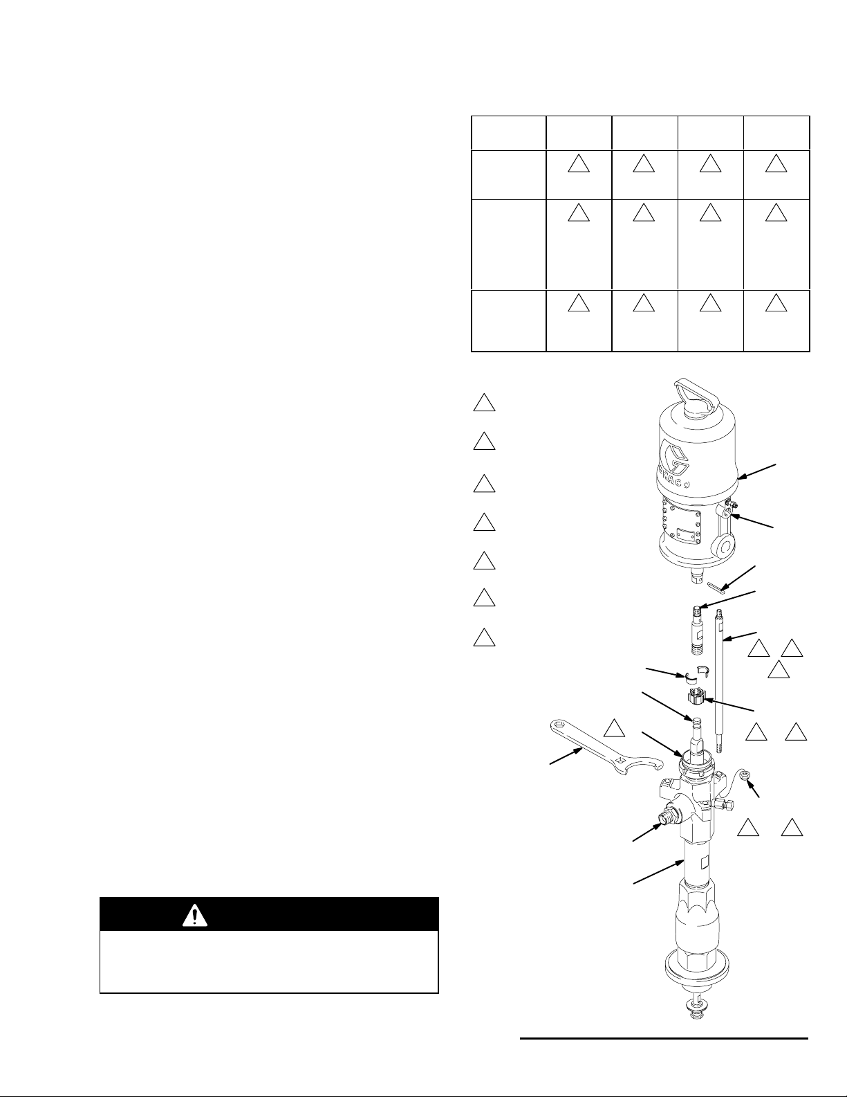
Reconnecting the Displacement Pump
1. Make sure the coupling nut (104) and the coupling
collars (105) are in place on the displacement rod
(1). See Fig. 4.
2. Orient the pump’s fluid outlet (8) to the air inlet
(CC) as was noted in step 4 under Disconnecting
the Displacement Pump. Position the displacement pump (107) on the tie rods (102).
NOTE: Refer to Fig. 4 and the Torque Chart for proper
torque values for your pump.
3. If you removed the tie rods (102) from the air
motor (101), reinstall them using an 11 mm
wrench. Torque as specified.
4. Screw the nuts (106) onto the tie rods (102) and
torque as specified.
5. Screw the coupling nut (104) onto the connecting
rod (103) or air motor shaft loosely. Hold the
connecting rod flats with a wrench to keep it from
turning. Using an adjustable wrench, torque the
coupling nut.
6. Using a torque wrench in the square hole of the
supplied wrench (110), torque the packing nut (2).
PUMP TORQUE CHART (Refer to Fig. 4)
Pump
Model
222768,
237207,
246933
222769,
222770,
222778,
222813,
224660,
235626
237208,
237492,
237779,
237780
Torque to 27–34 NSm
1
(20–25 ft-lb).
Torque to 45–53 NSm
2
(33–39 ft-lb).
Torque to 50–61 NSm
3
(37–45 ft-lb).
Torque to 20–25 NSm
4
(15–18 ft-lb).
Torque to 36–45 NSm
5
(27–33 ft-lb).
Torque to 195–210 NSm
6
(145–155 ft-lb).
Torque to 81–89 NSm
7
(60–66 ft-lb).
Tie Rod
(102)
4 1 3 2
5 1 3 2
7 7 6 2
Tie Rod
Nut (106)
Coupling
Nut (104)
105
1
Packing
Nut (2)
101
CC
111
103
102
4
, 5 ,
or
7
7. Mount the pump and reconnect all hoses. Reconnect the ground wire if it was disconnected. Fill the
wet-cup (2) 1/3 full of Graco Throat Seal Liquid or
compatible solvent.
8. Turn on the air supply. Run the pump slowly to
ensure proper operation.
WARNING
To reduce the risk of serious injury whenever you
are instructed to relieve pressure, always follow the
Pressure Relief Procedure on page 9.
9. Before returning the pump to production, relieve
the pressure and retorque the packing nut (2).
110
Model 222768
President Pump
Shown
Fig. 4
2
107
104
2
3
or
6
106
1
or 7
8
0424A
308017 15
Page 16

Service
Displacement Pump Service
Disassembly
When disassembling the pump, lay out all removed
parts in sequence, to ease reassembly.
NOTE: Repair Kit 222773 is available for Displacement
Pumps 222790, 237206, 237450 and 246933. The kit
includes piston and intake seals and cylinder o-rings.
For the best results, use all the new parts in the kit. Kit
parts are marked with one asterisk, for example (11*).
Repair Kits 222774 (UHMWPE/PTFE), 222775
(PTFE), 237916 (UHMWPE/leather), and 234422
(UHMWPE/Tuffstack) are available to replace the
throat packings. For the best results, use all the new
parts in the kit. Kit parts are marked with a symbol, for
example (3{). See page 32.
Repair Kit 222793 is available to service the intake
valve of Displacement Pumps 222790, 237206,
237450 and 246933. For the best results, use all the
new parts in the kit. Kit parts are marked with a symbol, for example (19}).
1. Remove the displacement pump from the air motor
as explained on page 14. Place the pump in a
vise, with the jaws on the outlet housing (10).
2. Hold the flats of the priming piston rod (24) with a
12 mm wrench. Using a 22 mm wrench, unscrew
the priming piston nut (30). Slide the priming piston
(25) and piston guide (31) off the rod. Inspect the
surfaces of the guide (31) and piston (25) for
scoring, wear, or other damage.
3. Loosen the packing nut (2) using the wrench (110)
supplied, or a hammer and brass rod. Remove the
intake cylinder (23), using an adjustable wrench.
4. Unscrew the intake valve housing (17) from the
cylinder (12), using an adjustable wrench. Pull the
housing off the pump. The intake check valve
assembly (DD) should slide down the priming
piston rod (24) as you remove the housing; if it
does not slide easily, firmly tap on the top of the
housing (17) with a rubber mallet to loosen.
5. Use an o-ring pick to remove the seal (21) from
the intake valve housing (17). Discard the seal;
use a new one for reassembly. Pull the intake
valve seat (22) out the bottom of the housing (17).
If the seat is difficult to remove, insert a brass rod
through the top of the housing and drive the seat
out with a hammer. Take care not to drop the
check valve assembly (DD) as it comes free, and
set it aside for later.
6. Push the displacement rod (1) down as far as
possible, then pull it and the priming piston rod
(24) out of the outlet housing (10) and cylinder
(12).
7. Remove the packing nut (2), throat packings (5
and/or 3) and glands (4 and 6) from the outlet
housing (10). Some models include a fluid outlet
nipple (8) and o-ring (9). Do not remove these
parts from the housing unless they need replacement.
8. Unscrew the bleeder valve plug (35) completely
from the valve body (43). Clean the valve threads
and the bleed hole. It is not necessary to remove
the valve body from the pump outlet housing (10).
9. Use a 400 mm adjustable wrench on the flats of
the pump cylinder (12) and unscrew the cylinder
from the outlet housing (10). Remove the o-rings
(11). Inspect the inside surface of the cylinder for
wear, scoring or other damage by holding it up to
the light at an angle or running a finger over the
surface.
10. Inspect the outer surfaces of the displacement rod
(1) and priming piston rod (24) for wear, scoring or
other damage by holding them up to the light at an
angle or running a finger over the surface.
11. Use a vise with soft jaws to hold the displacement
rod (1) by its flats. Place a 19 mm wrench on the
flats of the piston and unscrew the piston (13) and
priming piston rod (24) from the displacement rod
(1). Remove the spacer (33). Disassemble the
piston guide (14) from the piston (13).
12. It is not necessary to remove the priming piston
rod (24) from the piston (13) unless your inspection reveals scoring, wear, or other damage to
either part. To disassemble, place the piston flats
in a vise and unscrew the rod, using a 12 mm
wrench on the flats.
16 308017
Page 17

Throat Packing Detail
4
5
or
3
Service
1
3
2
1
Lips of v-packings must face down.
2
See Detail at right.
3
Valve Plug (remove and clean).
4
Valve Body (do not remove).
5
Remove only if damaged.
6
9
8
5
43
10
4
35
3
Detail of Piston and
Intake Check Valve
1
11
(Ref)
12
33
14
2
12
(Ref)
13
11
17
(Ref)
Fig. 5
23
17
22
21
24
31
25
30
DD
15
16
2
42
18
DD
19
*20
24
(Ref)
0425B
308017 17
Page 18

Service
13. Place the flats of the piston seat (16) in a vise.
Using a 13 mm (1/2 in.) dia. brass rod (EE), unscrew the piston guide (14) from the piston seat
(16). See Fig. 6. Remove the piston seal (15);
always replace with a new one. Inspect the mating
surfaces of the piston (13) and piston seat (16) for
nicks, scoring or wear.
16
EE
14. To disassemble the intake check valve (DD), place
the nut (18) in a vise and unscrew the intake valve
body (19), using a 28 mm wrench. See Fig. 7.
Remove the seals (42, 20) from the nut and from
the valve body; always replace them with new
ones. Inspect the mating surfaces of the intake
valve body (19) and seat (22) for wear, scoring, or
other damage.
NOTE: The seal (42) is press-fit in the nut (18) and
may require cutting to ease removal.
15. Inspect all parts for damage and clean with a
compatible solvent. To reassemble, refer to page
19.
18
Fig. 6
14
0205
19
0206
Fig. 7
18 308017
Page 19

Service
Reassembly (Refer to Fig. 8)
1. Place a 13 mm (1/2 in.) diameter brass rod lengthwise in a vise. Install a new piston seal (15*) on
the piston seat. Apply thread sealant to the
threads of the piston seat. Place the piston guide
(14) securely on the brass rod. Using a 32 mm
crow’s-foot, screw the piston seat (16) into the
piston guide. Torque to 27–34 N.m (20–25 ft-lb).
2. If it was necessary to remove the priming piston
rod (24) from the piston (13), apply thread sealant
to the threads of the rod. Place the flats of the
piston (13) in a vise. Hold the flats of the rod with a
12 mm wrench, and screw the rod into the piston.
Torque to 45–53 N.m (33–39 ft-lb).
3. Use a vise with soft jaws to hold the displacement
rod (1) by its flats. Install the spacer (33, see the
following note) on the rod. Install the assembled
piston guide/seat on the piston (13). Apply thread
sealant to the threads of the displacement rod, and
screw the piston assembly onto the rod, using a 19
mm wrench on the flats of the piston. Torque to
120–130 N.m (88–95 ft-lb). There will be a small
gap between the top of the piston (13) and the
shoulder of the rod (1).
NOTE: The piston spacer (33) is not required when
pumping fluids with a viscosity greater than 1 million
centipoise.
4. Lubricate the threads of the bleeder valve plug
(35). The plug has two sets of threads. Be sure to
screw the plug completely into the valve body (43).
Torque the plug to 30–38
NOTE: Some models include an outlet nipple (8) and
o-ring (9*). It is not ordinarily necessary to remove
these parts. However, if they were replaced because of
damage, lubricate the o-ring and place it on the nipple.
Screw the nipple into the outlet housing (10). Torque to
70–75 N.m (51–55 ft-lb).
5. Lubricate the o-rings (11*) and install them on the
cylinder (12). Apply thread lubricant to the top
threads of the cylinder. Using a 400 mm wrench on
the flats of the cylinder, screw it into the outlet
housing (10). Torque to 325–354 N.m (240–260
ft-lb).
NSm (22–28 ft-lb).
308017 19
Page 20

Service
6. Lubricate the throat packings and glands, and
install them in the outlet housing (10) one at a time
in the following order, with the lips of the v-pack-
ings facing down: the male gland (6{), v-pack-
ings (see the NOTE below), and the female gland
(4{). Apply thread lubricant to the packing nut (2)
and install the nut loosely in the outlet housing.
NOTE: Refer to page 32 for the correct throat packing
configuration for your pump.
7. Carefully insert the displacement rod (1) into the
bottom of the cylinder (12). Push the rod up into
the cylinder and through the outlet housing (10),
until it protrudes from the packing nut (2). Be
careful not to damage the piston seal (15*) while
performing this step.
8. Apply thread lubricant to the bottom threads of the
cylinder (12). Be sure the o-ring (11*) is in place on
the cylinder. Guide the intake valve housing (17)
up onto the priming piston rod (24) and screw it
onto the cylinder, using an adjustable wrench.
Torque to 325–354 N.m (240–260 ft-lb).
12. Place a 26 mm wrench on the flats of the packing
nut (18) and a 28 mm wrench on the flats of the
valve body (19). Screw the nut into the body,
making certain they remain in position above the
flats of the rod (24). Torque to 45–53 N.m (33–39
ft-lb). Slide the assembled intake check valve up
the priming piston rod until it reaches the stop
(FF); this may be difficult due to high friction
between the seal and rod.
13. Position the intake valve seat (22) so its large
beveled side faces down toward the pump intake.
Slide the seat (22) onto the priming piston rod (24)
and into the intake valve housing (17) until it seats
on the lower lip of the housing. Lubricate a new
seal (21*) and push it up into the gap around the
bottom outer edge of the seat (22).
14. Apply thread lubricant to the threads of the intake
cylinder (23) and screw the cylinder into the intake
valve housing (17), using an adjustable wrench.
Torque to 325–354 N.m (240–260 ft-lb).
9. With the beveled side facing up, press the seal
(42) into the recess of the intake packing nut (18)
until it snaps into place. The nose of the seal
should be flush with or slightly recessed into the
face of the packing nut.
10. Apply sealant to the threads of the intake packing
nut (18). With the threads facing down toward the
pump intake, slide the nut up onto the priming
piston rod (24) until it clears the flats of the rod.
11. Lubricate a new intake valve seal (20*) and slide it
onto the rod, being careful not to damage the seal
when passing over the flats of the rod. Slide the
seal up until it reaches the packing nut (18). Apply
sealant to the female threads of the intake valve
body (19), and slide it onto the rod until it reaches
the nut (18).
15. Slide the priming piston guide (31) onto the rod
(24) until it stops. Then install the priming piston
(25) with the flat side of the priming piston (25)
facing up toward the pump. Apply thread sealant to
the threads of the priming piston rod (24). Hold the
rod steady with a 12 mm wrench on the flats, and
screw the priming piston nut (30) onto the rod with
a 22 mm wrench. Torque to 45–53 N.m (33–39
ft-lb).
16. Reconnect the displacement pump to the air motor
as explained on page 15.
17. Allow 2 hours for the thread sealant to cure before
returning the pump to service.
20 308017
Page 21

Throat Packing Detail
{4
1
13
{5
or
{3
{6
*9
13
8
10
1
3{
13
Service
1
2
9
10
4
43
35
1
Lips of v-packings must face down.
2
See Detail at right.
Lubricate threads and screw completely into
3
body (43). Torque to 30–38 N.m (22–28 ft-lb).
Valve Body (bleed hole must face down).
4
Apply thread sealant.
5
6
Large bevel must face down.
7
Flat side must face up.
8
Torque to 27–34 NSm (20–25 ft-lb).
9
Torque to 45–53 NSm (33–39 ft-lb).
10
Torque to 70–75 NSm (51–55 ft-lb).
11
Torque to 120–130 NSm (88–95 ft-lb).
12
3
Torque to 325–354 NSm (240–260 ft-lb).
13
Lubricate.
Detail of Piston and
Intake Check Valve
12
23
13
12
12
13
1
(Ref)
12
11*
13
33
2
14
11
12
(Ref)
*11
13
17
(Ref)
5
8
*15
17
2
22
6
16
5
9
*21
24
FF
42
Fig. 8
31
25
30
18
9
DD
19
13
5
*20
24
(Ref)
0425B
7
9
308017 21
Page 22

Notes
22 308017
Page 23

Model 222770, Series A
10:1 Ratio Monark Pump
(UHMWPE and PTFE Packed)
Parts
Model 235626, Series A
10:1 Ratio Monark Pump (PTFE Packed)
Ref.
No. Part No. Description Qty.
101 222791 AIR MOTOR, Monark
See 307043 for parts 1
102n 24B190 KIT, tie rod 3
103 184092 ROD, adapter 1
104n 184059 NUT, coupling 1
105n 184128 COLLAR, coupling 2
106n 109209 NUT, hex, self-locking; M10 x 1.5 3
107 222790 PUMP, displacement;
Used on Model 222770 only
See pages 30 & 31 for parts 1
235540 PUMP, displacement;
Used on Model 235626 only
See pages 30 & 31 for parts 1
108 184077 PLATE, adapter 1
109n 109212 SCREW, cap, socket hd;
3/8–16 unc–3a x 0.75” (19 mm) 3
110n 184119 WRENCH, packing nut 1
111n 101946 PIN, cotter 1
n These parts are included in Connection Kit 236070.
101
111n
108
n109
102n
103
n105
n104
110n
106n
107
0427A
308017 23
Page 24

Parts
Model 222768, Series A
20:1 Ratio President Pump
(UHMWPE and PTFE Packed)
Ref.
No. Part No. Description Qty.
101 222772 AIR MOTOR, President
See 306982 for parts 1
102n 24B190 KIT, tie rod 3
103 184091 ROD, adapter 1
104n 184059 NUT, coupling 1
105n 184128 COLLAR, coupling 2
106n 109209 NUT, hex, self-locking; M10 x 1.5 3
107 222790 PUMP, displacement
See pages 30 & 31 for parts 1
110n 184119 WRENCH, packing nut 1
111n 101946 PIN, cotter 1
n These parts are included in Connection Kit 236070.
101
Model 237207, Series A
20:1 Ratio Stubby President Pump
(UHMWPE and PTFE Packed)
Ref.
No. Part No. Description Qty.
101 222772 AIR MOTOR, President
See 306982 for parts 1
102 24B191 KIT, tie rod 3
103 237251 ROD, adapter 1
106 109209 NUT, hex, self-locking; M10 x 1.5 3
107 237206 PUMP, displacement
See pages 30 & 31 for parts 1
110 184119 WRENCH, packing nut 1
111 101946 PIN, cotter 1
112 156082 O-RING; buna-N 1
101
n110
103
n105
n104
107
111n
102n
106n
110
111
112
102
103
106
107
24 308017
05666A
0424A
Page 25

Parts
Model 246933, Series A
20:1 Ratio President Pump
(Tuffstack Throat Packed)
Ref.
No. Part No. Description Qty.
101 222772 AIR MOTOR, President
See 306982 for parts 1
102n 24B190 KIT, tie rod 3
103 184091 ROD, adapter 1
104n 184059 NUT, coupling 1
105n 184128 COLLAR, coupling 2
106n 109209 NUT, hex, self-locking; M10 x 1.5 3
107 246932 PUMP, displacement
See pages 30 & 31 for parts 1
110n 184119 WRENCH, packing nut 1
111n 101946 PIN, cotter 1
n These parts are included in Connection Kit 236070.
n110
101
111n
103
102n
n105
n104
106n
107
0424A
308017 25
Page 26

Parts
Model 222769, Series A
34:1 Ratio Senator Pump (shown)
(UHMWPE and PTFE Packed)
Model 224660, Series A
34:1 Ratio Quiet Senator Pump
(UHMWPE and PTFE Packed)
Ref.
No. Part No. Description Qty.
101 217540 AIR MOTOR, Senator, standard
Used on Model 222769;
See 307592 for parts 1
220571 AIR MOTOR, Senator, quiet
Used on Model 224660;
See 307592 for parts 1
102n 124B190 KIT, tie rod 3
103 184127 ROD, adapter 1
104n 184059 NUT, coupling 1
105n 184128 COLLAR, coupling 2
106n 109209 NUT, hex, self-locking; M10 x 1.5 3
107 222790 PUMP, displacement
See pages 30 & 31 for parts 1
108 184094 PLATE, adapter 1
109n 109211 SCREW, cap, socket hd;
5/8–11 unc–2a x 2” (51 mm) 3
110n 184119 WRENCH, packing nut 1
n These parts are included in Connection Kit 236070.
101
108
102n
n109
103
n105
n104
107
110n
106n
0428A
26 308017
Page 27

Parts
Model 237492, Series A
34:1 Ratio Stubby Senator Pump (shown)
(UHMWPE and PTFE Packed)
Model 237780, Series A
34:1 Ratio Stubby Quiet Senator Pump
(UHMWPE and PTFE Packed)
Ref.
No. Part No. Description Qty.
101 217540 AIR MOTOR, Senator, standard
Used on Model 237492;
See 307592 for parts 1
220571 AIR MOTOR, Senator, quiet
Used on Model 237780;
See 307592 for parts 1
102n 190000 ROD, tie; 224 mm (8.82”)
shoulder to shoulder 3
104n 186925 NUT, coupling 1
105n 184129 COLLAR, coupling 2
106n 106166 NUT, hex, self-locking; M16 x 2.0 3
107 237450 PUMP, displacement
See pages 30 & 31 for parts 1
110n 112887 WRENCH, packing nut 1
102
101
105
104
n These parts are included in Connection Kit 235417.
110
106
107
05668A
308017 27
Page 28

Parts
Model 222778, Series A
55:1 Ratio Bulldog Pump (shown)
(UHMWPE and PTFE Packed)
Model 222813, Series A
55:1 Ratio Quiet Bulldog Pump
(UHMWPE and PTFE Packed)
Ref.
No. Part No. Description Qty.
101 208356 AIR MOTOR, Bulldog, standard
Used on Model 222778
See 307049 for parts 1
215255 AIR MOTOR, Bulldog, quiet
Used on Model 222813
See 307304 for parts 1
102n 24B190 KIT, tie rod 3
103 184127 ROD, adapter 1
104n 184059 NUT, coupling 1
105n 184128 COLLAR, coupling 2
106n 109209 NUT, hex, self-locking; M10 x 1.5 3
107 222790 PUMP, displacement
See pages 30 & 31 for parts 1
108 184094 PLATE, adapter 1
109n 109211 SCREW, cap, socket hd;
5/8–11 unc–2a x 2” (51 mm) 3
110n 184119 WRENCH, packing nut 1
n These parts are included in Connection Kit 236070.
101
108
n109
102n
103
n105
n104
107
110n
106n
0429A
28 308017
Page 29

Parts
Model 237208, Series A
55:1 Ratio Stubby Bulldog Pump (shown)
(UHMWPE and PTFE Packed)
Model 237779, Series A
55:1 Ratio Stubby Quiet Bulldog Pump
(UHMWPE and PTFE Packed)
Ref.
No. Part No. Description Qty.
101 208356 AIR MOTOR, Bulldog, standard
Used on Model 237208
See 307049 for parts 1
215255 AIR MOTOR, Bulldog, quiet
Used on Model 237779
See 307304 for parts 1
102n 190000 ROD, tie; 224 mm (8.82”)
shoulder to shoulder 3
104n 186925 NUT, coupling 1
105n 184129 COLLAR, coupling 2
106n 106166 NUT, hex, self-locking; M16 x 2.0 3
107 237450 PUMP, displacement
See pages 30 & 31 for parts 1
110n 112887 WRENCH, packing nut 1
102
101
105
104
n These parts are included in Connection Kit 235417.
110
106
107
05667A
308017 29
Page 30

Displacement Pump Parts
NOTE: Refer to page 32 for the available throat packing kits.
Model 222790, Series B Displacement Pump, UHMWPE and PTFE Packings
Model 235540, Series A Displacement Pump, PTFE Packings
Model 237206, Series A Displacement Pump, UHMWPE and PTFE Packings, Stubby Pump
Model 237450, Series A Displacement Pump, UHMWPE and PTFE Packings, Stubby Pump
Model 246932, Series A Displacement Pump, Tuffstack throat, UHMWPE and PTFE Packings
Ref.
No. Part No. Description Qty.
1 184041 ROD, displacement; sst;
328.25 mm (12.92 in.) long;
used on Models 222790 & 235540 1
190159 ROD, displacement; sst;
252.45 mm (9.94 in.) long;
used on Model 237206 1
190172 ROD, displacement; sst;
328.25 mm (12.92 in.) long;
used on Model 237450 1
2 184039 NUT, packing; carbon steel;
used on Models 222790,
235540, and 237206 1
236577 NUT, packing; carbon steel;
used on Model 237450 1
7Y 184090 LABEL, warning 1
8 184037 NIPPLE, outlet; M30 x 1.5(m);
3/4 npt(m); carbon steel;
used on Models 222790,
235540, and 237206 only 1
9* 110135 O-RING; PTFE;
used on Models 222790,
235540, and 237206 only 1
10 184038 HOUSING, outlet; ductile iron;
used on Models 222790,
235540, and 237206 1
189389 HOUSING, outlet; ductile iron;
used on Model 237450 1
11* 109205 O-RING; PTFE 2
12 184040 CYLINDER, pump; sst 1
13 184042 PISTON; alloy steel 1
14 184043 GUIDE, piston; alloy steel 1
15* 184053 SEAL, piston; UHMWPE;
used on Models 222790,
237450, and 237206 1
188257 SEAL, piston; PTFE;
used on Model 235540;
(not included in Repair Kit 222773) 1
Ref.
No. Part No. Description Qty.
16 184052 SEAT, piston; alloy steel 1
17 184044 HOUSING, intake valve; ductile iron 1
18 184493 NUT, packing, intake valve;
carbon steel 1
19} 184616 VALVE BODY, intake; alloy steel 1
20*} 184049 SEAL, intake valve; PTFE 1
21*} 187860 SEAL; acetal 1
22} 184617 SEAT, intake valve; alloy steel 1
23 187859 CYLINDER, intake; ductile iron 1
24 187858 ROD, priming piston; sst 1
25 184051 PISTON, priming; carbon steel 1
30 184121 NUT, priming piston; alloy steel 1
31 184122 GUIDE, priming piston; alloy steel 1
33 184124 SPACER, piston; sst 1
35 190128 PLUG, bleeder valve 1
37Y 184151 LABEL, warning 1
39Y 172479 TAG, instruction (not shown) 1
42*} 184469 SEAL, intake valve; UHMWPE;
used on Models 222790,
237450, and 237206 1
189217 SEAL, intake valve; PTFE;
used on Model 235540;
(not included in Repair Kits
222773 and 222793) 1
43 165702 BODY, bleeder valve 1
* These parts are included in Seal Repair Kit 222773, which
may be purchased separately.
} These parts are included in Intake Seat Repair Kit
222793, which may be purchased separately.
Y Replacement Danger and Warning labels, tags and cards
are available at no cost.
30 308017
Page 31

Displacement Pump Parts
Model 222790 Shown
1
Refer to page 32 for available throat packing kits.
2
Seal Repair Kit 222773 does not include Piston Seal 188257 or Intake Valve Seal 189217 used on pump 235540.
3
Intake Seat Repair Kit 222793 does not include Intake Valve Seal 189217 used on pump 235540.
4
Used on Models 222790, 235540, and 237206 only.
2
1
42*}
18
32
1
33
20*}
19}
14
10
*9
4
8
4
43
35
15*
16
2
22}
21*}
13
23
*11
12
24 (Ref)
24
*11
1 (Ref)
17
31
25
30
05938A
308017 31
Page 32

Throat Packing Kits
UHMWPE and PTFE Throat Packing Repair Kit 222774,
used on Displacement Pumps 222790, 237206, and 237450
Ref.
No. Part No. Description Qty.
3{ 109302 V-PACKING; PTFE 2
4{ 184172 GLAND, female; sst 1
5{ 109252 V-PACKING; UHMWPE 3
6{ 184222 GLAND, male; sst 1
{ These parts are included in Throat Packing Repair Kit
222774, which may be purchased separately.
4
Lips of v-packings must face down.
{4
{5
4
{6
PTFE Throat Packing Repair Kit 222775,
used on Displacement Pump 235540
3{ 109302 V-PACKING; PTFE 5
4{ 184172 GLAND, female; sst 1
6{ 184222 GLAND, male; sst 1
{ These parts are included in Throat Packing Repair Kit
222775, which may be purchased separately.
4
Lips of v-packings must face down.
{4
4
{3
{6
UHMWPE and Leather Throat Packing Conversion Kit 237916,
for use with all Displacement Pumps
3{
4
Ref.
No. Part No. Description Qty.
3{ 184302 V-PACKING; leather 2
4{ 184172 GLAND, female; sst 1
5{ 109252 V-PACKING; UHMWPE 3
6{ 184222 GLAND, male; sst 1
{ These parts are included in Throat Packing Repair Kit
237916, which may be purchased separately.
4
Lips of v-packings must face down.
{4
{5
4
{6
Tuffstack and UHMWPE Throat Packing Conversion Kit 234422,
used on Displacement Pump 246932
Ref.
No. Part No. Description Qty.
3{ 109327 V-PACKING; Tuffstack 2
4{ 184172 GLAND, female; sst 1
5{ 109252 V-PACKING; UHMWPE 3
6{ 184222 GLAND, male; sst 1
{ These parts are included in Throat Packing Repair Kit
234422, which may be purchased separately.
4
Lips of v-packings must face down.
{4
{5
4
{6
3{
3{
4
4
32 308017
Page 33

Technical Data (Monark Pumps)
WARNING
Be sure that all fluids and solvents used are chemically compatible with the
Wetted Parts listed below. Always read the manufacturer’s literature before
using fluid or solvent in this pump.
Category Data
Ratio 10:1
Maximum fluid working pressure 12 MPa, 124 bar (1800 psi)
Maximum air input pressure 1.2 MPa, 12 bar (180 psi)
Pump cycles per 3.8 liters (1 gal.) 60
Fluid flow at 60 cycles/min 3.8 liters/min (1.0 gpm)
Air motor effective diameter 76 mm (3”)
Stroke length 76 mm (3”)
Displacement pump effective area 4.5 cm@ (0.697 in.@)
Maximum pump operating temperature 82_C (180_F)
Weight 21 kg (45 lb)
Wetted parts Carbon Steel; E52100, 41L40, and 4140 Alloy Steel;
304, 316 and 17-4 PH Grades of Stainless Steel;
Ductile Iron; Zinc and Nickel Plating; PTFE; Acetal;
Ultra-High Molecular Weight Polyethylene (not used on
Displacement Pump 235540)
Sound Pressure Levels (dBa)
(measured at 1 meter from unit)
Input Air Pressures at 15 cycles per minute
Air Motor 40 psi (0.28 MPa, 2.8 bar) 70 psi (0.48 MPa, 4.8 bar) 100 psi (0.7 MPa, 7 bar)
Monark 62.6 dB(A) 62.5 dB(A) 63.9 dB(A)
Sound Power Levels (dBa)
(tested in accordance with ISO 9614–2)
Input Air Pressures at 15 cycles per minute
Air Motor 40 psi (0.28 MPa, 2.8 bar) 70 psi (0.48 MPa, 4.8 bar) 100 psi (0.7 MPa, 7 bar)
Monark 69.5 dB(A) 70.7 dB(A) 71.0 dB(A)
308017 33
Page 34

Technical Data (Monark Pumps)
KEY: Fluid Outlet Pressure - Black Curves
Air Consumption - Gray Curves
A 1.2 MPa, 12 bar (180 psi) Air Pressure
B 0.7 MPa, 7 bar (100 psi) Air Pressure
C 0.49 MPa, 4.9 bar (70 psi) Air Pressure
psi
bar
MPa
1800
124
12
1500
105
10
1200
84
900
63
600
42
300
21
gpm
liters/min
A
8
B
6
C
4
2
0
0.0 0.5 1.0 1.5
(TEST FLUID: 1900 CENTIPOISE OIL)
cycles/min
30 90
1.9
FLUID FLOW
60
3.8 5.7
psi
bar
MPa
scfm
m#/min
30
0.840
24
A
0.672
18
0.504
B
12
0.336
C
6
0.168
1800
124
12
1500
105
10
1200
84
900
63
600
42
300
21
gpm
liters/min
A
8
B
6
4
C
2
0
0.0 0.2 0.4 0.6 0.8 1.0
(TEST FLUID: 100,000 CENTIPOISE SEALANT)
cycles/min
20 80
40
60
C
1.52
FLUID FLOW
3.042.280.76
scfm
m#/min
30
0.840
24
0.672
18
0.504
A
12
0.336
B
6
0.168
3.80
To find Fluid Outlet Pressure (MPa/bar/psi) at a specific fluid flow
(lpm/gpm) and operating air pressure (MPa/bar/psi):
1. Locate desired flow along bottom of chart.
2. Follow vertical line up to intersection with selected fluid outlet
pressure curve (black). Follow left to scale to read fluid outlet
pressure.
To find Pump Air Consumption (m#/min or scfm) at a specific fluid
flow (lpm/gpm) and air pressure (MPa/bar/psi):
1. Locate desired flow along bottom of chart.
2. Read vertical line up to intersection with selected air consumption
curve (gray). Follow right to scale to read air consumption.
34 308017
Page 35

Technical Data (President Pumps)
WARNING
Be sure that all fluids and solvents used are chemically compatible with the
Wetted Parts listed below. Always read the manufacturer’s literature before
using fluid or solvent in this pump.
Category Data
Ratio 20:1
Maximum fluid working pressure 25 MPa, 248 bar (3600 psi)
Maximum air input pressure 1.2 MPa, 12 bar (180 psi)
Pump cycles per 3.8 liters (1 gal.) 48
Fluid flow at 60 cycles/min 4.5 liters/min (1.2 gpm)
Air motor effective diameter 108 mm (4.25”)
Stroke length 102 mm (4”)
Displacement pump effective area 4.5 cm@ (0.697 in.@)
Maximum pump operating temperature 82_C (180_F)
Weight 22.7 kg (50 lb)
Wetted parts Carbon Steel; E52100, 41L40, and 4140 Alloy Steel;
304, 316 and 17-4 PH Grades of Stainless Steel;
Ductile Iron; Zinc and Nickel Plating; PTFE; Acetal;
Ultra-High Molecular Weight Polyethylene (not used on
Displacement Pump 235540)
Sound Pressure Levels (dBa)
(measured at 1 meter from unit)
Input Air Pressures at 15 cycles per minute
Air Motor 40 psi (0.28 MPa, 2.8 bar) 70 psi (0.48 MPa, 4.8 bar) 100 psi (0.7 MPa, 7 bar)
President 73.6 dB(A) 78.3 dB(A) 80.9 dB(A)
Sound Power Levels (dBa)
(tested in accordance with ISO 9614–2)
Input Air Pressures at 15 cycles per minute
Air Motor 40 psi (0.28 MPa, 2.8 bar) 70 psi (0.48 MPa, 4.8 bar) 100 psi (0.7 MPa, 7 bar)
President 87.4 dB(A) 92.1 dB(A) 94.6 dB(A)
308017 35
Page 36

Technical Data (President Pumps)
KEY: Fluid Outlet Pressure - Black Curves
Air Consumption - Gray Curves
A 1.2 MPa, 12 bar (180 psi) Air Pressure
B 0.7 MPa, 7 bar (100 psi) Air Pressure
C 0.49 MPa, 4.9 bar (70 psi) Air Pressure
D 0.28 MPa, 2.8 bar (40 psi) Air Pressure
psi
bar
MPa
3600
250
25
3000
210
21
2400
168
16
1800
126
12
1200
84
8
600
42
4
0
0.0 0.5 1.0 1.5 2.0
gpm
liters/min
24 96
A
B
C
D
1.9
(TEST FLUID: 1900 CENTIPOISE OIL)
cycles/min
48 72
3.8 7.6
FLUID FLOW
5.7
psi
bar
MPa
scfm
m#/min
75
2.10
A
60
1.68
45
1.26
B
30
C
D
0.84
15
0.42
3600
250
25
3000
210
21
2400
168
16
1800
126
12
1200
84
600
42
gpm
liters/min
A
B
C
8
D
4
0
0.0 0.5 1.0 1.5 2.0
1.9
(TEST FLUID: 100,000 CENTIPOISE SEALANT)
25
cycles/min
50 75
3.8 7.6
FLUID FLOW
5.7
scfm
m#/min
75
2.10
A
60
1.68
45
1.26
B
30
0.84
C
D
15
0.42
To find Fluid Outlet Pressure (MPa/bar/psi) at a specific fluid flow
(lpm/gpm) and operating air pressure (MPa/bar/psi):
1. Locate desired flow along bottom of chart.
2. Follow vertical line up to intersection with selected fluid outlet
pressure curve (black). Follow left to scale to read fluid outlet
pressure.
To find Pump Air Consumption (m#/min or scfm) at a specific fluid
flow (lpm/gpm) and air pressure (MPa/bar/psi):
1. Locate desired flow along bottom of chart.
2. Read vertical line up to intersection with selected air consumption
curve (gray). Follow right to scale to read air consumption.
36 308017
Page 37

Technical Data (Senator Pumps)
WARNING
Be sure that all fluids and solvents used are chemically compatible with the
Wetted Parts listed below. Always read the manufacturer’s literature before
using fluid or solvent in this pump.
Category Data
Ratio 34:1
Maximum fluid working pressure 28 MPa, 281 bar (4080 psi)
Maximum air input pressure 0.8 MPa, 8 bar (120 psi)
Pump cycles per 3.8 liters (1 gal.) 38
Fluid flow at 60 cycles/min 6 liters/min (1.6 gpm)
Air motor effective diameter 146 mm (5.75”)
Stroke length 120 mm (4.7”)
Displacement pump effective area 4.5 cm@ (0.697 in.@)
Maximum pump operating temperature 82_C (180_F)
Weight 45.5 kg (100 lb)
Wetted parts Carbon Steel; E52100, 41L40, and 4140 Alloy Steel;
304, 316 and 17-4 PH Grades of Stainless Steel;
Ductile Iron; Zinc and Nickel Plating; PTFE; Acetal;
Ultra-High Molecular Weight Polyethylene (not used on
Displacement Pump 235540)
Sound Pressure Levels (dBa)
(measured at 1 meter from unit)
Input Air Pressures at 15 cycles per minute
Air Motor 40 psi (0.28 MPa, 2.8 bar) 70 psi (0.48 MPa, 4.8 bar) 100 psi (0.7 MPa, 7 bar)
Senator 84.3 dB(A) 87.8 dB(A) 91.2 dB(A)
Sound Power Levels (dBa)
(tested in accordance with ISO 9614–2)
Input Air Pressures at 15 cycles per minute
Air Motor 40 psi (0.28 MPa, 2.8 bar) 70 psi (0.48 MPa, 4.8 bar) 100 psi (0.7 MPa, 7 bar)
Senator 91.6 dB(A) 94.6 dB(A) 97.3 dB(A)
308017 37
Page 38

Technical Data (Senator Pumps)
KEY: Fluid Outlet Pressure - Black Curves
Air Consumption - Gray Curves
A 0.7 MPa, 7 bar (100 psi) Air Pressure
B 0.49 MPa, 4.9 bar (70 psi) Air Pressure
C 0.28 MPa, 2.8 bar (40 psi) Air Pressure
psi
bar
MPa
3600
250
25
3000
210
21
2400
168
16
1800
126
12
1200
84
8
600
42
4
0
0.0 0.5 1.0 1.5 2.0 2.5
gpm
liters/min
19 95
A
B
C
1.9
(TEST FLUID: 1900 CENTIPOISE OIL)
cycles/min
38 76
3.8 7.6
FLUID FLOW
57
5.7
psi
bar
MPa
scfm
m#/min
75
A
2.10
60
B
1.68
45
1.26
C
30
0.84
15
0.42
9.5
3600
250
25
3000
210
21
2400
168
16
1800
126
12
1200
84
8
600
42
4
0
0.0 0.5 1.0 1.5 2.0 2.5
gpm
liters/min
(TEST FLUID: 100,000 CENTIPOISE SEALANT)
20
A
B
C
1.9
cycles/min
40 80
3.8 7.6
FLUID FLOW
60
5.7
scfm
m#/min
75
A
B
C
2.10
60
1.68
45
1.26
30
0.84
15
0.42
9.5
To find Fluid Outlet Pressure (MPa/bar/psi) at a specific fluid flow
(lpm/gpm) and operating air pressure (MPa/bar/psi):
1. Locate desired flow along bottom of chart.
2. Follow vertical line up to intersection with selected fluid outlet
pressure curve (black). Follow left to scale to read fluid outlet
pressure.
To find Pump Air Consumption (m#/min or scfm) at a specific fluid
flow (lpm/gpm) and air pressure (MPa/bar/psi):
1. Locate desired flow along bottom of chart.
2. Read vertical line up to intersection with selected air consumption
curve (gray). Follow right to scale to read air consumption.
38 308017
Page 39

Technical Data (Quiet Senator Pumps)
WARNING
Be sure that all fluids and solvents used are chemically compatible with the
Wetted Parts listed below. Always read the manufacturer’s literature before
using fluid or solvent in this pump.
Category Data
Ratio 34:1
Maximum fluid working pressure 28 MPa, 281 bar (4080 psi)
Maximum air input pressure 0.8 MPa, 8 bar (120 psi)
Pump cycles per 3.8 liters (1 gal.) 38
Fluid flow at 60 cycles/min 6 liters/min (1.6 gpm)
Air motor effective diameter 146 mm (5.75”)
Stroke length 120 mm (4.7”)
Displacement pump effective area 4.5 cm@ (0.697 in.@)
Maximum pump operating temperature 82_C (180_F)
Weight 45.5 kg (100 lb)
Wetted parts Carbon Steel; E52100, 41L40, and 4140 Alloy Steel;
304, 316 and 17-4 PH Grades of Stainless Steel;
Ductile Iron; Zinc and Nickel Plating; PTFE; Acetal;
Ultra-High Molecular Weight Polyethylene (not used on
Displacement Pump 235540)
Sound Pressure Levels (dBa)
(measured at 1 meter from unit)
Input Air Pressures at 15 cycles per minute
Air Motor 40 psi (0.28 MPa, 2.8 bar) 70 psi (0.48 MPa, 4.8 bar) 100 psi (0.7 MPa, 7 bar)
Quiet Senator 83.4 dB(A) 84.3 dB(A) 88.5 dB(A)
Sound Power Levels (dBa)
(tested in accordance with ISO 9614–2)
Input Air Pressures at 15 cycles per minute
Air Motor 40 psi (0.28 MPa, 2.8 bar) 70 psi (0.48 MPa, 4.8 bar) 100 psi (0.7 MPa, 7 bar)
Quiet Senator 89.8 dB(A) 91.8 dB(A) 94.4 dB(A)
308017 39
Page 40

Technical Data (Quiet Senator Pumps)
KEY: Fluid Outlet Pressure - Black Curves
Air Consumption - Gray Curves
A 0.7 MPa, 7 bar (100 psi) Air Pressure
B 0.49 MPa, 4.9 bar (70 psi) Air Pressure
C 0.28 MPa, 2.8 bar (40 psi) Air Pressure
psi
bar
MPa
3600
250
25
3000
210
21
2400
168
16
1800
126
12
1200
84
8
600
42
4
0
0.0 0.5 1.0 1.5 2.0 2.5
gpm
liters/min
19 95
A
B
C
1.9
(TEST FLUID: 1900 CENTIPOISE OIL)
cycles/min
38 76
3.8 7.6
FLUID FLOW
57
5.7
psi
bar
MPa
scfm
m#/min
75
2.10
A
60
1.68
B
45
1.26
C
30
0.84
15
0.42
9.5
3600
250
25
3000
210
21
2400
168
16
1800
126
12
1200
84
8
600
42
4
0
0.0 0.5 1.0 1.5 2.0 2.5
gpm
liters/min
20
A
B
C
1.9
(TEST FLUID: 100,000 CENTIPOISE SEALANT)
cycles/min
40 80
3.8 7.6
FLUID FLOW
60
5.7
scfm
m#/min
75
A
B
C
2.10
60
1.68
45
1.26
30
0.84
15
0.42
9.5
To find Fluid Outlet Pressure (MPa/bar/psi) at a specific fluid flow
(lpm/gpm) and operating air pressure (MPa/bar/psi):
1. Locate desired flow along bottom of chart.
2. Follow vertical line up to intersection with selected fluid outlet
pressure curve (black). Follow left to scale to read fluid outlet
pressure.
To find Pump Air Consumption (m#/min or scfm) at a specific fluid
flow (lpm/gpm) and air pressure (MPa/bar/psi):
1. Locate desired flow along bottom of chart.
2. Read vertical line up to intersection with selected air consumption
curve (gray). Follow right to scale to read air consumption.
40 308017
Page 41

Technical Data (Bulldog Pumps)
WARNING
Be sure that all fluids and solvents used are chemically compatible with the
Wetted Parts listed below. Always read the manufacturer’s literature before
using fluid or solvent in this pump.
Category Data
Ratio 55:1
Maximum fluid working pressure 34 MPa, 341 bar (4950 psi)
Maximum air input pressure 0.6 MPa, 6.2 bar (90 psi)
Pump cycles per 3.8 liters (1 gal.) 40
Fluid flow at 60 cycles/min 5.7 liters/min (1.5 gpm)
Air motor effective diameter 146 mm (5.75”)
Stroke length 120 mm (4.7”)
Displacement pump effective area 4.5 cm@ (0.697 in.@)
Maximum pump operating temperature 82_C (180_F)
Weight 45.5 kg (100 lb)
Wetted parts Carbon Steel; E52100, 41L40, and 4140 Alloy Steel;
304, 316 and 17-4 PH Grades of Stainless Steel;
Ductile Iron; Zinc and Nickel Plating; PTFE; Acetal;
Ultra-High Molecular Weight Polyethylene (not used on
Displacement Pump 235540)
Sound Pressure Levels (dBa)
(measured at 1 meter from unit)
Input Air Pressures at 15 cycles per minute
Air Motor 40 psi (0.28 MPa, 2.8 bar) 70 psi (0.48 MPa, 4.8 bar) 90 psi (0.6 MPa, 6.2 bar)
Bulldog 82.4 dB(A) 87.3 dB(A) 88.5 dB(A)
Sound Power Levels (dBa)
(tested in accordance with ISO 9614–2)
Input Air Pressures at 15 cycles per minute
Air Motor 40 psi (0.28 MPa, 2.8 bar) 70 psi (0.48 MPa, 4.8 bar) 90 psi (0.6 MPa, 6.2 bar)
Bulldog 91.6 dB(A) 95.9 dB(A) 97.4 dB(A)
308017 41
Page 42

Technical Data (Bulldog Pumps)
KEY: Fluid Outlet Pressure - Black Curves
Air Consumption - Gray Curves
A 0.6 MPa, 6.2 bar (90 psi) Air Pressure
B 0.49 MPa, 4.9 bar (70 psi) Air Pressure
C 0.28 MPa, 2.8 bar (40 psi) Air Pressure
psi
bar
MPa
5000
350
35
4000
280
28
3000
210
21
2000
140
14
1000
70
7
0
0.0 0.5 1.0 1.5 2.0 2.5
gpm
liters/min
20
A
B
C
1.9
(TEST FLUID: 1900 CENTIPOISE OIL)
cycles/min
40 80
3.8 7.6
FLUID FLOW
60
5.7
psi
bar
MPa
scfm
m#/min
A
120
3.36
B
C
9.5
90
2.52
60
1.68
30
0.84
5000
350
35
4000
280
28
3000
210
21
2000
140
14
1000
70
7
0
0.0 0.5 1.0 1.5 2.0 2.5
gpm
liters/min
(TEST FLUID: 100,000 CENTIPOISE SEALANT)
20
A
B
C
1.9
cycles/min
40 80
3.8 7.6
FLUID FLOW
60
5.7
scfm
m#/min
A
120
3.36
B
C
9.5
90
2.52
60
1.68
30
0.84
To find Fluid Outlet Pressure (MPa/bar/psi) at a specific fluid flow
(lpm/gpm) and operating air pressure (MPa/bar/psi):
1. Locate desired flow along bottom of chart.
2. Follow vertical line up to intersection with selected fluid outlet
pressure curve (black). Follow left to scale to read fluid outlet
pressure.
To find Pump Air Consumption (m#/min or scfm) at a specific fluid
flow (lpm/gpm) and air pressure (MPa/bar/psi):
1. Locate desired flow along bottom of chart.
2. Read vertical line up to intersection with selected air consumption
curve (gray). Follow right to scale to read air consumption.
42 308017
Page 43

Technical Data (Quiet Bulldog Pumps)
WARNING
Be sure that all fluids and solvents used are chemically compatible with the
Wetted Parts listed below. Always read the manufacturer’s literature before
using fluid or solvent in this pump.
Category Data
Ratio 55:1
Maximum fluid working pressure 34 MPa, 341 bar (4950 psi)
Maximum air input pressure 0.6 MPa, 6.2 bar (90 psi)
Pump cycles per 3.8 liters (1 gal.) 40
Fluid flow at 60 cycles/min 5.7 liters/min (1.5 gpm)
Air motor effective diameter 146 mm (5.75”)
Stroke length 120 mm (4.7”)
Displacement pump effective area 4.5 cm@ (0.697 in.@)
Maximum pump operating temperature 82_C (180_F)
Weight 45.5 kg (100 lb)
Wetted parts Carbon Steel; E52100, 41L40, and 4140 Alloy Steel;
304, 316 and 17-4 PH Grades of Stainless Steel;
Ductile Iron; Zinc and Nickel Plating; PTFE; Acetal;
Ultra-High Molecular Weight Polyethylene (not used on
Displacement Pump 235540)
Sound Pressure Levels (dBa)
(measured at 1 meter from unit)
Input Air Pressures at 15 cycles per minute
Air Motor 40 psi (0.28 MPa, 2.8 bar) 70 psi (0.48 MPa, 4.8 bar) 90 psi (0.6 MPa, 6.2 bar)
Quiet Bulldog 81.5 dB(A) 83.6 dB(A) 85.6 dB(A)
Sound Power Levels (dBa)
(tested in accordance with ISO 9614–2)
Input Air Pressures at 15 cycles per minute
Air Motor 40 psi (0.28 MPa, 2.8 bar) 70 psi (0.48 MPa, 4.8 bar) 90 psi (0.6 MPa, 6.2 bar)
Quiet Bulldog 90.2 dB(A) 93.5 dB(A) 94.9 dB(A)
308017 43
Page 44

Technical Data (Quiet Bulldog Pumps)
KEY: Fluid Outlet Pressure - Black Curves
Air Consumption - Gray Curves
A 0.6 MPa, 6.2 bar (90 psi) Air Pressure
B 0.49 MPa, 4.9 bar (70 psi) Air Pressure
C 0.28 MPa, 2.8 bar (40 psi) Air Pressure
psi
bar
MPa
5000
350
35
4000
280
28
3000
210
21
2000
140
14
1000
70
7
0
0.0 0.5 1.0 1.5 2.0 2.5
gpm
liters/min
20
A
B
C
1.9
(TEST FLUID: 1900 CENTIPOISE OIL)
cycles/min
40 80
60
A
B
C
3.8 7.6
FLUID FLOW
5.7
9.5
scfm
m#/min
120
3.36
90
2.52
60
1.68
30
0.84
psi
bar
MPa
5000
350
35
4000
280
28
3000
210
21
2000
140
14
1000
70
7
0
0.0 0.5 1.0 1.5 2.0 2.5
gpm
liters/min
(TEST FLUID: 100,000 CENTIPOISE SEALANT)
20
A
B
C
1.9
cycles/min
40 80
3.8 7.6
FLUID FLOW
60
5.7
scfm
m#/min
9.5
120
3.36
90
2.52
60
1.68
30
0.84
A
B
C
To find Fluid Outlet Pressure (MPa/bar/psi) at a specific fluid flow
(lpm/gpm) and operating air pressure (MPa/bar/psi):
1. Locate desired flow along bottom of chart.
2. Follow vertical line up to intersection with selected fluid outlet
pressure curve (black). Follow left to scale to read fluid outlet
pressure.
To find Pump Air Consumption (m#/min or scfm) at a specific fluid
flow (lpm/gpm) and air pressure (MPa/bar/psi):
1. Locate desired flow along bottom of chart.
2. Read vertical line up to intersection with selected air consumption
curve (gray). Follow right to scale to read air consumption.
44 308017
Page 45

Notes
308017 45
Page 46
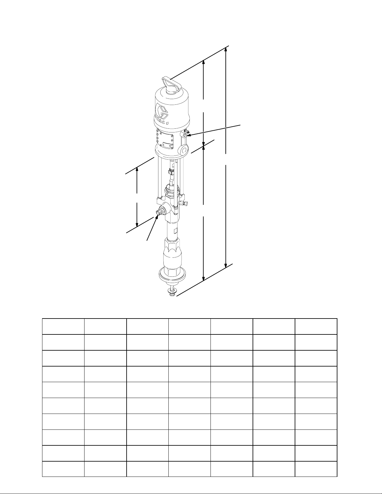
Dimensions
Model 222768 Shown
D
B
E
A
46 308017
Pump
Model
222770,
235626
222768,
246932
237207 1119 mm
222769,
224660
237492 1329 mm
237780 1329 mm
222778,
222813
237208 1329 mm
237779 1329 mm
A B C D E
1188 mm
(46.25 in.)
1251 mm
(49.25 in.)
(44.07 in.)
1400 mm
(55.1 in.)
(52.32 in.)
(52.32 in.)
1400 mm
(55.1 in.)
(52.32 in.)
(52.32 in.)
F
365 mm
(14.35 in.)
418 mm
(16.45 in.)
418 mm
(16.45 in.)
570 mm
(22.4 in.)
570 mm
(22.4 in.)
570 mm
(22.4 in.)
570 mm
(22.4 in.)
570 mm
(22.4 in.)
570 mm
(22.4 in.)
826 mm
(32.5 in.)
832 mm
(32.75 in.)
700 mm
(27.57 in.)
830 mm
(32.7 in.)
759 mm
(29.88 in.)
759 mm
(29.88 in.)
830 mm
(32.7 in.)
759 mm
(29.88 in.)
759 mm
(29.88 in.)
C
0423A
F
328 mm
(12.9 in.)
328 mm
(12.9 in.)
196 mm
(7.7 in.)
322 mm
(12.7 in.)
251 mm
(9.9 in.)
251 mm
(9.9 in.)
322 mm
(12.7 in.)
251 mm
(9.9 in.)
251 mm
(9.9 in.)
(air inlet)
3/8 npt(f) 3/4 npt(m)
1/2 npt(f) 3/4 npt(m)
1/2 npt(f) 3/4 npt(m)
3/4 npsm(f) 3/4 npt(m)
3/4 npsm(f) 3/4 npt(f)
3/4 npsm(f) 3/4 npt(f)
3/4 npsm(f) 3/4 npt(m)
3/4 npsm(f) 3/4 npt(f)
3/4 npsm(f) 3/4 npt(f)
(fluid outlet)
Page 47

Mounting Hole Layout
PRESIDENT PUMPS MONARK PUMPS
7.9 mm
(0.312”)
diameter (2)
diameter (3)
11.4 mm
(0.449”)
63.5 mm
(2.50”)
54.1 mm
(2.130”)
62.50 mm
(2.461”)
31.25 mm
(1.230”)
62.50 mm
(2.461”)
0213 0214
38.5 mm
(1.516”)
31.2 mm
(1.230”)
diameter (3)
11.4 mm
(0.449”)
SENATOR AND BULLDOG PUMPS
63.5 mm
(2.50”)
54.1 mm
(2.131”)
22.2 mm
(0.875”)
44.5 mm
(1.750”)
7.1 mm
(0.281”)
diameter (2)
101.6 mm
(4.0”)
50.8 mm
(2.0”)
94.28 mm
(3.712”)
94.28 mm
(3.712”)
88 mm
(3.464”)
54.13 mm
(2.131”)
17 mm
(0.669”)
diameter (3)
11.5 mm
(0.453”)
diameter (4)
62.50 mm
(2.461”)
31.25 mm
(1.230”)
0431
308017 47
Page 48

Graco Standard Warranty
Graco warrants all equipment manufactured by Graco and bearing its name to be free from defects in material and workmanship on the
date of sale to the original purchaser for use. With the exception of any special, extended, or limited warranty published by Graco,
Graco will, for a period of twelve months from the date of sale, repair or replace any part of the equipment determined by Graco to be
defective. This warranty applies only when the equipment is installed, operated and maintained in accordance with Graco’s written
recommendations.
This warranty does not cover, and Graco shall not be liable for general wear and tear, or any malfunction, damage or wear caused by
faulty installation, misapplication, abrasion, corrosion, inadequate or improper maintenance, negligence, accident, tampering, or substitution of non–Graco component parts. Nor shall Graco be liable for malfunction, damage or wear caused by the incompatibility of
Graco equipment with structures, accessories, equipment or materials not supplied by Graco, or the improper design, manufacture,
installation, operation or maintenance of structures, accessories, equipment or materials not supplied by Graco.
This warranty is conditioned upon the prepaid return of the equipment claimed to be defective to an authorized Graco distributor for
verification of the claimed defect. If the claimed defect is verified, Graco will repair or replace free of charge any defective parts. The
equipment will be returned to the original purchaser transportation prepaid. If inspection of the equipment does not disclose any defect
in material or workmanship, repairs will be made at a reasonable charge, which charges may include the costs of parts, labor, and
transportation.
THIS WARRANTY IS EXCLUSIVE, AND IS IN LIEU OF ANY OTHER WARRANTIES, EXPRESS OR IMPLIED, INCLUDING BUT
NOT LIMITED TO WARRANTY OF MERCHANTABILITY OR WARRANTY OF FITNESS FOR A PARTICULAR PURPOSE.
Graco’s sole obligation and buyer’s sole remedy for any breach of warranty shall be as set forth above. The buyer agrees that no other
remedy (including, but not limited to, incidental or consequential damages for lost profits, lost sales, injury to person or property, or any
other incidental or consequential loss) shall be available. Any action for breach of warranty must be brought within two (2) years of the
date of sale.
Graco makes no warranty, and disclaims all implied warranties of merchantability and fitness for a particular purpose in connection
with accessories, equipment, materials or components sold but not manufactured by Graco. These items sold, but not manufactured
by Graco (such as electric motors, switches, hose, etc.), are subject to the warranty, if any, of their manufacturer. Graco will provide
purchaser with reasonable assistance in making any claim for breach of these warranties.
In no event will Graco be liable for indirect, incidental, special or consequential damages resulting from Graco supplying equipment
hereunder, or the furnishing, performance, or use of any products or other goods sold hereto, whether due to a breach of contract,
breach of warranty, the negligence of Graco, or otherwise.
FOR GRACO CANADA CUSTOMERS
The parties acknowledge that they have required that the present document, as well as all documents, notices and legal proceedings
entered into, given or instituted pursuant hereto or relating directly or indirectly hereto, be drawn up in English. Les parties reconnaissent avoir convenu que la rédaction du présente document sera en Anglais, ainsi que tous documents, avis et procédures judiciaires
exécutés, donnés ou intentés à la suite de ou en rapport, directement ou indirectement, avec les procedures concernées.
Graco Information
TO PLACE AN ORDER, contact your Graco distributor, or call this number to identify the distributor closest to you:
1–800–328–0211 Toll Free
612–623–6921
612–378–3505 Fax
All written and visual data contained in this document reflects the latest product information available at the time of publication.
Graco reserves the right to make changes at any time without notice.
48 308017
This manual contains English. MM 308017
Graco Headquarters: Minneapolis
International Offices: Belgium, China, Japan, Korea
GRACO INC. P.O. BOX 1441 MINNEAPOLIS, MN 55440–1441
Copyright 1990, Graco Inc. is registered to ISO 9001
www.graco.com
Revised 12/2008
 Loading...