

Page 1
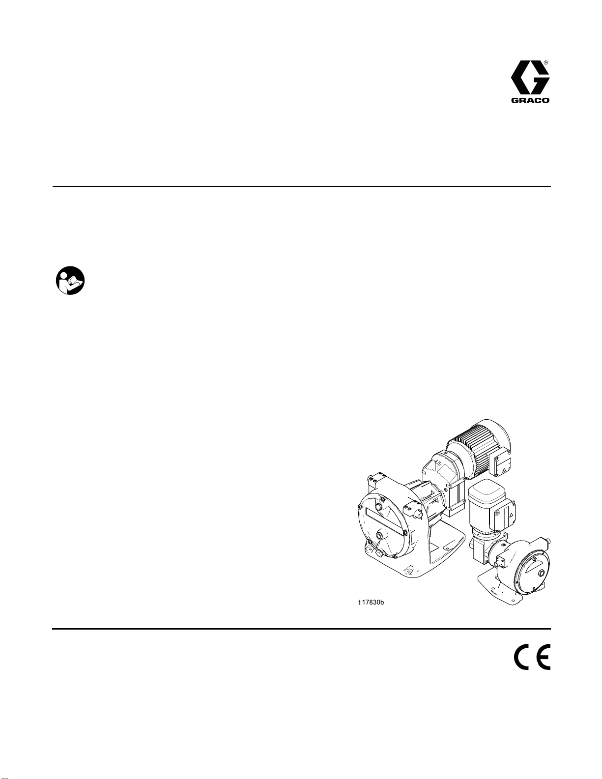
Operation
EP Hose Pumps
3A1938E
Electric-powered hose pump for use in fluid transfer and metering applications. For professional use
only.
Not approved for use in explosive atmospheres or hazardous locations.
Important Safety Instructions
Read all warnings and instructions in this manual.
Save these instructions.
125 psi (0
Working Pressure
See page 3 for model part numbers and
informa
.9 MPa, 9 bar) Maximum Fluid
tion.
EN
PROVEN QUALITY. LEADING TECHNOLOGY.
Page 2

Contents
Models............................................................... 3
Warnings ........................................................... 4
Installatio
Operation........................................................... 18
n.......................................................... 7
Receiving an
Moving the Pu
Location ...................................................... 8
Mount the Pu
MountingaN
Fluid Conne
Lubricate t
Grounding
Electrica
Setup the V
Flush Pump Before Using............................. 18
Pressure Relief Procedure............................ 18
d Handling................................ 7
mp......................................... 7
mp .......................................... 8
on-Graco Motor........................ 8
ctions ........................................ 9
he Pump ...................................... 10
................................................... 12
l Connections.................................. 13
FD............................................. 17
Pre-Start Checklist ....................................... 18
Start the Pump............................................. 18
Running the Pump ....................................... 19
Shutdown.................................................... 19
Storage ....................................................... 19
Maintenance ...................................................... 20
Preventive Maintenance Schedule ................ 20
Flushing ...................................................... 20
Pump Bearing Lubrication ............................ 20
Hose Lubrication.......................................... 20
Dimensions........................................................ 21
Mounting Hole Layouts ....................................... 22
Technical Data ...................................................23
Performance Data .............................................. 26
Graco Standard Warranty.................................... 28
2
3A1938E
Page 3

Models
Models
Pump Model
EP2006
EP2013
EP3019
EP4029
Hose ID Size
(mm)
6
13
19
29
Reference
See EP2 Repair-Parts Manual for a complete list of pump
part numbers and descriptive information.
See EP2 Repair-Parts Manual for a complete list of pump
part numbers and descriptive information.
See EP3 Rep
part numbe
See EP4 Repair-Parts Manual for a complete list of pump
part numbers and descriptive information.
air-Parts Manual for a complete list of pump
rs and descriptive information.
3A1938E 3
Page 4
Warnings
Warnings
The following
exclamation p
risks. When th
Warnings. Pr
the body of th
warnings are for the setup, use, grounding, maintenance and repair of this equipment. The
oint symbol alerts you to a general warning and the hazard symbol refers to procedure-specific
ese symbols appear in the body of this manual or on warning labels, refer backtothese
oduct-specific hazard symbols and warnings not covered in this section may appear throughout
is manual where applicable.
WARNING
FIRE AND EX
Flammable fumes, such as solvent and paint fumes, in work area can ignite or explode. To help
prevent fire and explosion:
• Use equipment only in well ventilated area.
• Eliminate all ignition sources; such as pilot lights, cigarettes, portable electric lamps, and
plastic drop cloths (potential static arc).
• Keep work
• Do not plug or unplug power cords, or turn power or light switches on or off when flammable
fumes are present.
• Ground all equipment in the work area. See Grounding instructions.
•Useonly
• Hold gun firmly to side of grounded pail when triggering into pail.
• If there is static sparking or you feel a shock, stop operation immediately. Do not use
equipment until you identify and correct the problem.
• Keepaw
PLOSION HAZARD
area free of debris, including solvent, rags and gasoline.
grounded hoses.
orking fire extinguisher in the work area.
ELECTRIC SHOCK HAZARD
This equipment must be grounded. Improper grounding, setup, or usage of the system can
cause electric shock.
•Turno
• Connect only to grounded power source.
• All electrical wiring must be done by a qualified electrician and comply with all local codes
MOV
Mov
• Keep clear of moving parts.
•Don
• Pressurized equipment can start without warning. Before checking, moving, or servicing
ff and disconnect power at main switch before disconnecting any cables and before
cing or installing equipment.
servi
and regulations.
ING PARTS HAZARD
ing parts can pinch, cut or amputate fingers and other body parts.
ot operate equipment with protective guards or covers removed.
equipment, follow the Pressure Relief Procedure and disconnect all power sources.
4
3A1938E
Page 5
WARNING
ENTANGLEMENT HAZARD
Rotating parts can cause serious injury.
Warnings
• Keep clear of
• Do not operate equipment with protective guards or covers removed.
• Do not wear loose clothing, jewelry or long hair while operating equipment.
•Equipmentca
the Pressur
TOXIC FLUID OR FUMES
Toxic fluids or fumes can cause serious injury or death if splashed in the eyesoronskin,
inhaled, or swallowed.
• Read MSDSs
• Store hazardous fluid in approved containers, and dispose of it according to applicable
guidelines.
PERSONAL PROTECTIVE EQUIPMENT
You must wear appropriate protective equipment when operating, servicing, or when in the
operating area of the equipment to help protect you from serious injury, including eye injury,
hearing loss, inhalation of toxic fumes, and burns. This equipment includes but is not limited to:
• Protective eyewear, and hearing protection.
• Respirators, protective clothing, and gloves as recommended by the fluid and solvent
manufacturer.
PRESSU
Fluid f
and ca
RIZED EQUIPMENT HAZARD
rom the equipment, leaks, or ruptured components can splash in the eyes or onskin
use serious injury.
moving parts.
n start without warning. Before checking, moving or servicing equipment, follow
e Relief Procedure and disconnect all power sources.
to know the specific hazards of the fluids you are using.
• Follow the Pressure Relief Procedure when you stop spraying/dispensing and before
cleaning, checking, or servicing equipment.
•Tight
• Check hoses, tubes, and couplings daily. Replace worn or damaged parts immediately.
en all fluid connections before operating the equipment.
3A1938E 5
Page 6
Warnings
WARNING
EQUIPMENT MISUSE HAZARD
Misuse can cause death or serious injury.
• Do not operat
• Do not exceed the maximum working pressure or temperature rating of the lowest rated
system component. See Technical Data in all equipment manuals.
• Use fluids and solvents that are compatible with equipment wetted parts. See Technical Data
in all equipment manuals. Read fluid and solvent manufacturer’s warnings. For complete
information about your material, request MSDS from distributor or retailer.
• Do not leave
• Turn off all equipment and follow the Pressure Relief Procedure when equipment is not in use.
• Check equipment daily. Repair or replace worn or damaged parts immediately with genuine
manufacturer’s replacement parts only.
• Do not alte
• Use equipment only for its intended purpose. Call your distributor for information.
• Route hoses and cables away from traffic areas, sharp edges, moving parts, and hot surfaces.
• Do not kin
• Keep children and animals away from work area.
• Comply with all applicable safety regulations.
e the unit when fatigued or under the influence of drugs or alcohol.
the work area while equipment is energized or under pressure.
r or modify equipment.
k or over bend hoses or use hoses to pull equipment.
6 3A1938E
Page 7
Installation
Installation
Installation of your pump involves potentially
hazardous procedures. Only trained and qualified
personnel who have read and who understand
the information in this manual should install this
equipment.
Receiving and Handling
Upon receipt of your pump:
• Carefully inspect the pump to verify that no damage
occurred during transit. Check the packing list to
ensure that all parts and accessories are present.
NOTE: If you find any damage or shortage,
immediately notify your Graco distributor.
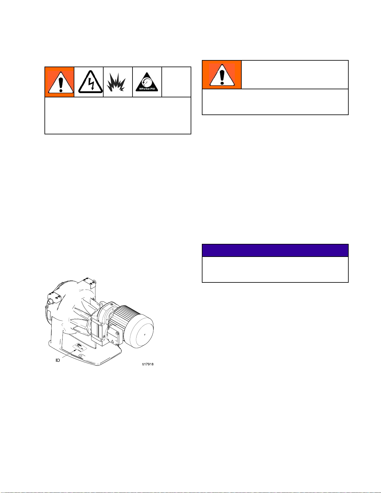
• Refer to the pump identification plate (ID) for the
pump part number and series level.
• Leave the pump assembly crated, horizontal, and
stored in a warm, dry location until you are ready
to install it. To store the pump more than 30 days,
see Storage, page 19.
Moving the Pump
The pump is heavy. Handle it carefully. Careless
handling can result in equipment damage and
injury to personnel.
After you receive and inspect your pump, transfer it
to the assembly location or storage area.
NOTE: To prevent hose damage if storing the pump
more than 30 days, see Storage, page 19.
Use the proper forklift truck for lifting equipment
on pallets or in crates. The lift forks should extend
under the equipment and completely support the
unit. When necessary to lift by crane, use the vertical
points of the equipment or the crating for pickup so
the equipment remains level. Use long lift cables,
chains, or straps, as required, to evenly support
the equipment. In addition, use a spreader bar, if
necessary, to ensure a vertical pull at all lift points.
Short cables or chains can create a cross shear that
can damage the equipment.
NOTICE
If your pump is supplied with a gear motor, lift only
with straps located under the gear motor and under
the front of the pump.
Figure 1 Pump Identification Plate
3A1938E
7
Page 8
Installation
Location
Allow sufficient space to permit easy access for
maintenance and service, especially in front of
the pump. The pump area should have adequate
headroom and sufficient ventilation.
Before installing your pump, see
Dimensions, page 21, to ensure that the
available space is sufficient for the pump, taking into
account the following provisions:
• Dimension and weight of the pump package.
• Required moving and hoisting equipment.
• Possible piping layout, including space for removal
and maintenance.
• Freedom of movement to operate the unit,
read speed and pressure gauges, and provide
adjustment and maintenance.
• Space required for lubrication.
• Space for removal of the hose from the unit.
• Location of the nearest drain or catch basin to
collect used lubricant and fluid.
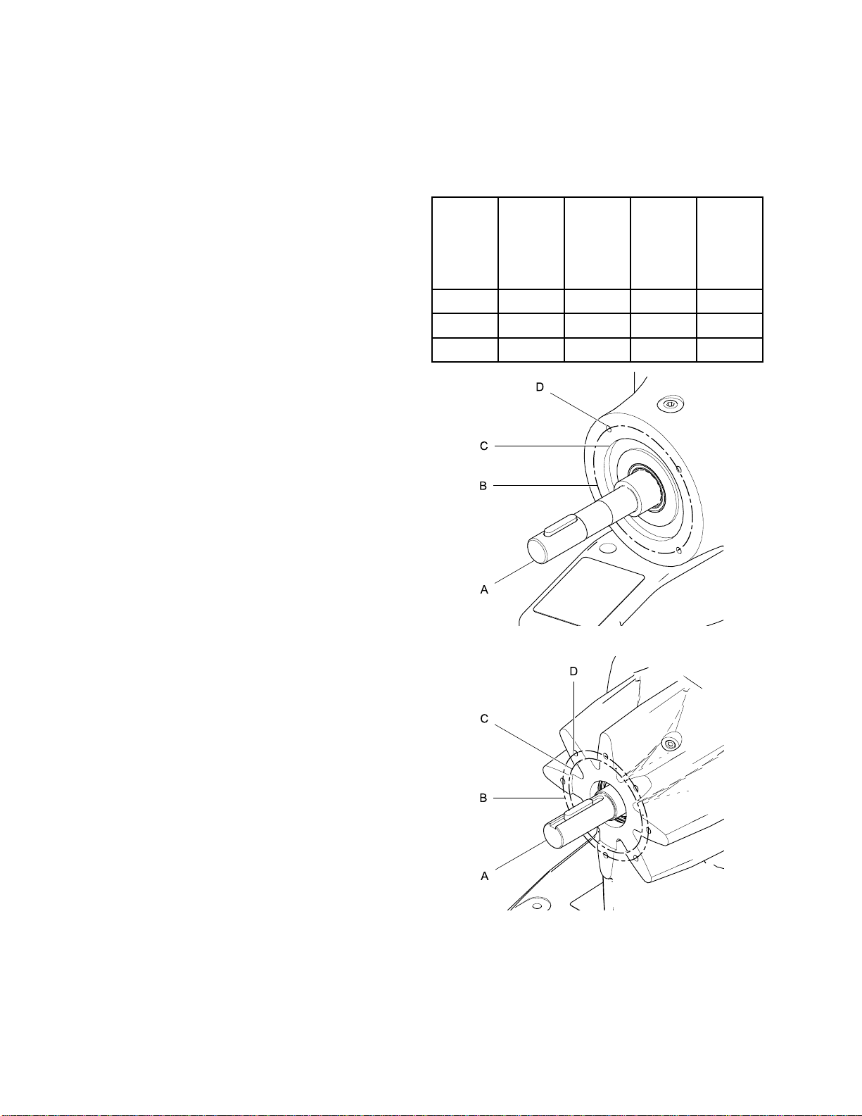
Mounting a Non
To mount a non-Graco motor and gearbox to a bare
EP Hose Pump, see the following table and Fig. 2
(EP2 Pumps) or Fig. 3 (EP3 or EP4 Pumps).
EP
Pump
Size
EP2 20 mm 100 mm 80 mm M6
EP3 30 mm 130 mm 110 mm M8
EP4 35 mm 165 mm 130 mm M10
Hollow
Bore
Shaft
Diameter (A)
-Graco Motor
Bolt Circle Diameter
(B)
Flange
Pilot Diameter
(C)
Mounting Hole
Thread
Size (D)
NOTE: The hose is serviced through the front cover.
Therefore, provide sufficient work space in front of
the pump when installing the unit.
Mount the Pump
See Mounting Hole Layouts, page 22.
Mount the pump on a flat concrete foundation 4
inches (100 mm) wider and longer than the pump
base. When installing the pump, make sure that the
surface of the foundation is smooth and free of debris.
The foundation should be level and of sufficient depth
and strength to adequately support the pump.
Anchor bolts should be set into the concrete
foundation. For best results, use anchor bolts made
of corrosion resistant material such as stainless
steel. Anchor bolt nuts should be of a different grade
stainless steel to prevent galling. Level the pump as
required, using shims.
Initially tighten the anchor bolts one eighth of a turn
with a wrench. Do not fully tighten until after all piping
has been connected.
Figure 2 Motor Mounting Dimensions for EP2 Pumps
Figure 3 Motor Mounting Dimensions for EP3 or
EP4 Pumps
8 3A1938E
Page 9
Installation
Fluid Connect
Undue stress on the pump inlet or outlet
connections can cause serious injury or equipment
failure. The fluid inlet and outlet lines must be
independently supported. The pipe supports
should be located as close to the pump as possible.
NOTE: The hose connections require the use of a
hose clamp. Part No. 24L497 Clamping Tool is
available from Graco.
Thepumpro
counter-c
motor rota
of roller m
fluid inle
Roller Di
(as viewe
sightgla
Clockwise Left
Counter-clockwise
lockwise, depending on the direction of
tion and the number of gears. The direction
ovement determines the orientation of the
t and outlet. See the table below.
rection
d through
ss)
ions
ller moves either clockwise or
Fluid Inl
Right
et
Fluid Outlet
Right
Left
Pump Model Fluid Inlet and
Outlet Size
EP2006 and EP2013 Pumps
EP3019 Pumps
EP4029 Pumps
Install a sh
the unit for
valveonthe
vacuum/pre
pump perfor
Fluid Outl
Thepumpo
as the out
pipe diam
As much as
downstr
utoff valve near the pump inlet to isolate
service and repair. Never install a check
inlet side of the pump. A compound
ssure gauge can be installed to monitor
mance.
et Line
utlet piping should be a similar diameter
let connection. Avoid sudden changes in
eter by using concentric taper increasers.
possible, provide a straight run of pipe
eam of the pump outlet.
1/2 npt(m)
3/4 npt(m)
1–1/4 npt(m)
NOTICE
Install a pressure relief valve upstream of a
shutoff valve at the pump outlet, to prevent
over-pressurization that can damage the pump or
the hose.
NOTE: If your installation requires the fluid inlet
and outlet positions to be reversed, this can
be done by reversing the motor rotation. See
Reverse Motor Direction, page 17.
Fluid Inlet Line
Locate the pump as close to the fluid source as
possible. The inlet piping should be at least the
same diameter as the pump inlet connection and
should have a straight run of pipe that is a minimum
of 8 to 10 pipe diameters long. Inlet piping must be
airtight and suitable for both pressure and vacuum.
If possible, provide a larger diameter pipe than the
pump inlet connection.
Install the pressure relief valve near the pump outlet.
Downstream of the pressure relief valve, install
a shutoff valve to isolate the unit for service and
repair. Install a pressure gauge to monitor pump
performance. A check valve is not recommended
on the outlet of the pump since the pump acts as its
own check valve.
3A1938E 9
Page 10

Installation
Flush Connections
Line flushing connections are recommended when
pumping slurries or liquids with a high concentration
of solids that tend to settle when the pump is turned
off.
NOTE: Accumulation of solids in the hose after
shutdown can reduce hose life because the hose will
experience high stress when restarting the pump.
Pulsation Dampeners
Hose pumps sometimes require the use of pulsation
dampeners on either the inlet or outlet to increase
the hose life during operation. A pulsation dampener
acts to absorb the energy of the pulsations that the
pump produces so that these forces do not act upon
the hose. Your Graco distributor will assist you in
selecting the proper size and application of these
devices in your system.
If your operation does require pulsation dampeners,
mount them as close to the inlet and/or outlet of the
pump as possible. Do not support the weight of the
dampeners on the pump connections. These devices
must be independently supported.
Outlet pulsation dampeners work best when there
is some back pressure in the outlet line. Pulsation
dampeners do not work efficiently at low outlet
pressures or when the pump discharges directly to
the atmosphere.
Drain and Vent Plugs
The pump is equipped with a low point drain (17)
and a vent (15). The drain is typically plugged with a
stainless steel plug, and the vent prevents a buildup
of excess pressure in the pump housing.
Lubricate the Pump
Before operating the pump, add hose lube to the
pump housing as explained below. Failure to do
so will result in reduced hose life. The hose lube
acts as a lubricant between the hose and the roller
and between the roller and the eccentric shaft.
It also dissipates heat from the hose. Check the
compatibility of the hose lube with your pumped fluid.
1. Disconnect the pump from the power source.
2. Remove the screws holding the motor fan cover.
Turn the fan by hand until the roller stops at the
bottom of the pump housing in the 6 o’clock
position.
NOTE: Therollermustbeinthe6o’clockposition
to prevent overfilling the pump with hose lube.
3. Unscrew the vent plug (15) near the top of the
cover.
4. Using a funnel, add hose lube through the vent
port. For EP3 and EP4 Models, the oil will be
visible through the sightglass (16). The oil level
must not rise above the halfway point on the
roller.
NOTE: Do not overfill. Overfilling the pump
housing with hose lube will increase pressure
inthepumphousing,causinghoselubetoleak
from the cover or the clamp area. See the table
below for the correct amount of hose lube for
your pump. Pre-measuring the correct amount
will help prevent overfilling.
Pump Model
EP2006, EP2013
EP3019
EP4029
NOTE: Higher operating speeds provide more
vigorous lubrication, which may cause splashing
of oil. When operating at a speed of 85 RPM
or greater, reduce the amount of hose lube as
shown in the table below.
-
Oper
g
atin
d
Spee
M)
(RP
0–84 As recommended in the table
85–104
105–114
15 and
1
bove
a
nt of Hose Lube
Amou
above.
% of recommended quantity
70
60% of recommended quantity
50% of recommended quantity
Amount of
(approx
8oz(250ml)
0.25 gal. (1 liter)
0.5 ga
Hose Lube
imate)
l. (2 liters)
10 3A1938E
Page 11

Figure 4 Fill Pump With Hose Lube
Installation
Figure 5 Hose Lube Level on EP3 and EP4
Pumps
Figure 6 Hose Lube Level on EP2 Pumps
5. Wrap the vent plug (15) threads with PTFE tape
and screw it into the vent port carefully.
NOTICE
The vent port threads are aluminum. To help
prevent galling, blow out the threads with
compressed air before installing the steel vent plug
(15).
3A1938E
11
Page 12

Installation
Grounding
This equipment must be grounded to reduce the
risk of static sparking and electric shock. Electric
or static sparking can cause fumes to ignite or
explode. Improper grounding can cause electric
shock. Grounding provides an escape wire for the
electric current.
1. Pump: The pump is grounded through
a proper electrical connection. See
Main Power Connections at the VFD, page 14.
2. Fluid hoses: Use only electrically conductive
hoses with a maximum of 500 ft. (150 m)
combined hose length to ensure grounding
continuity. Check the electrical resistance of
hoses. If total resistance to ground exceeds 25
megohms, replace hose immediately.
3. Fluid supply container: Follow your local code.
4. All solvent p
code. Use onl
Do not place
surface, su
interrupts
5. To maintain grounding continuity when flushing
or relieving pressure: Always hold the metal
nozzle firmly to the side of a grounded metal pail.
ails used when flushing: Follow local
y metal pails, which are conductive.
the pail on a non-conductive
ch as paper or cardboard, which
the grounding continuity.
2
1
3A1938E
Page 13

Installation
Electrical Co
nnections
All electrical wiring must be completed by a
qualified electrician and comply with all local codes
and regulations.
Wire Connections at the Motor
NOTE: Follow the instructions in the motor
manufacturer’s manual. Use a motor starter with
overload protection. Wire size, fuse size, and other
electrical devices must comply with all local codes
and regulations.
The motor must be wired to the VFD. Install the
wiring at the motor as follows:
1. Open the motor’s electrical box.
2. Install a strain relief in one of the ports at the
bottom of the motor box.
W2
U3
U1
U2
V3
V1
L2 L3L1
W2
T6
U1 U3
T1 T7
U2
T4
V1 V3
T2 T8
V2
T5
W1 W3
T3 T9
L3L2L1
Figure 7 Wire Connections for a 230 V Motor
V2
W3
W1
3. Connect the green ground wire to the ground
screw.
4. See Fig. 7 for 230 V motors and Fig. 8 for 460
V motors. Connect the wires to the bottom three
terminals (U, V, and W) in the motor box.
5. Close the motor electrical box.
W2
W3
U1
U2
U3
V1
V2
V3
W1
L2 L3L1
V1
T2
V2 V3
T5 T8
W1
T3
L3L2L1
W2 W3
T6 T9
U1
T1
U2 U3
T4 T7
Figure 8 Wire Connections for a 460 V Motor
3A1938E 13
Page 14

Installation
Wire Connections at the Variable Frequency Drive (VFD)
NOTE: Follow the instructions in the VFD
manufacturer’s manual.
Install the wi
1. Connect the wires to the motor. See
Wire Connections at the Motor, page 13.
2. Open the VFD’s electrical box.
3. Install strain reliefs in both ports at the bottom of
the VFD box.
4. Connect the green ground wire to the ground
screw.
5. Connect the wires from the motor terminals to
the matching terminals in the VFD box, as shown
in Fig. 9.
ring at the VFD as follows:
U/T1 V/T2 W/T3 PE
PES
PES
PES
PE
Main Power Connections at the VFD
All electrical wiring must be completed by a
qualified electrician and comply with all local codes
and regulations.
Connect the power supply wires to the VFD, as
follows:
1. Connect the wiring between the motor and VFD,
as detailed above.
2. Connect the green ground wire of the power
supply to the ground screw. The ground wire
from the motor is also connected to this screw.
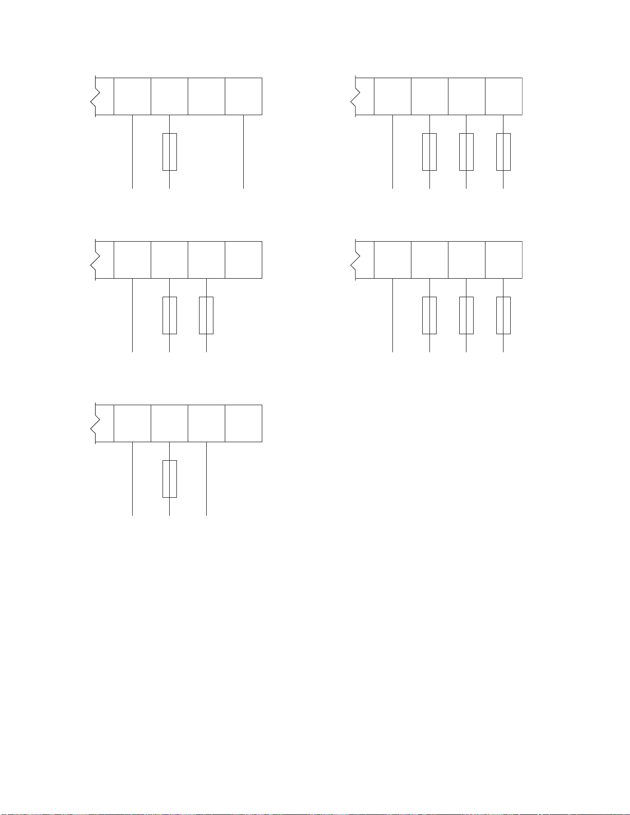
3. Connect the power supply wires to the power
terminals in the VFD box, following all local codes
and regulations. See Table 1 and Figs. 10–14,
as applicable for your system.
4. Close the VFD electrical box.
PES
PES
PE
Figure 9 Wire Connections from the Motor to the VFD
4
1
3A1938E
Page 15

Table 1 Main Power Connections at the VFD
Installation
VFD Part No. Used With Pump Input Voltage
16K905 EP2006 120 Vac, 1 phase 240 Vac, 3 phase Fig. 10
16K905 EP2006 240 Vac, 1 phase 240 Vac, 3 phase Fig. 11
16K906 EP2006 208–240 Vac,
phase
16K906 EP2006 208–240 Vac, 3
phase
16K907 EP2013 120 Vac, 1 phase 240 Vac, 3 phase Fig. 10
16K907 EP2013 240 Vac, 1 p
16K908 EP2013 208–240 Vac, 1
phase
16K908 EP2013 208–240 Vac, 3
phase
16K909 EP3019 120 Vac, 1
16K909 EP3019 240 Vac, 1 phase 240 Vac, 3 phase Fig. 11
16K910 EP3019 208–240 Vac, 1
phase
16K910 EP3019 208–24
phase
0Vac,3
1
hase
phase
Output Voltag
208–240 Vac,
phase
208–240 Vac, 3
phase
240 Vac, 3 p
208–240 Vac, 3
phase
208–240 Vac, 3
phase
240 Vac, 3
208–240 Vac, 3
phase
208–24
phase
e
3
hase
phase
0Vac,3
See Figure No.
Fig. 12
Fig. 13
Fig. 11
Fig. 12
Fig. 13
Fig. 10
Fig. 12
Fig. 13
16K911 EP4029 208–240 Vac, 1
phase
16K911 EP4029 208–240 Vac, 3
phase
16K91
2
EP402
9
400–4
phas
80 Vac 3
e
208–240 Vac, 3
phase
208–240 Vac, 3
phase
80 Vac 3
400–4
e
phas
Fig. 12
Fig. 13
Fig. 1
4
3A1938E 15
Page 16
Installation
PE L1 L2 N
PE L1 N
Figure 10 120 Vac 1 Phase Input/240 Vac 3 Phase
Output
PE L1 L2 N
PE L1 L2
Figure 11 240 Vac 1 Phase Input/240 Vac 3 Phase
Output
PE L1 L2 L3
PE L1 L2 L3
Figure 13 208–240 Vac 3 Phase Input/208–240 Vac
3 Phase Output
PE L1 L2 L3
PE L1 L2 L3
Figure 14 400–480 Vac 3 Phase Input/400–480 Vac
3 Phase Output
PE L1 L2 L3
PE L1 N
Figure 12 208–240 Vac 1 Phase Input/208–240 Vac
3PhaseOutput
16 3A1938E
Page 17

Installation
Setup the VFD
VFD Control Panel
NOTE: For complete information about the VFD, see
the manufacturer’s instructions supplied with the
VFD.
• The control
motor. It al
FWD (forwar
• The green RU
•TheredSTO
•Usethearr
motor.
• The blue R/
Reverse M
• The blue M
manufact
and infor
NOTE: If
to scrol
panel display shows the status of the
so shows the direction of motor rotation:
d) or REV (reverse).
N key starts the motor.
P key stops the motor.
ow keys to speed up or slow down the
F key changes the motor rotation (see
otor Direction, page 17).
key accesses the VFD menu. See the
urer’s instructions for menu descriptions
mation.
the M key is pressed, use the arrow keys
l through the VFD menu.
Reverse Motor Direction
NOTE: VFD Parameter P112 controls the direction of
motor rotation. The VFD is shipped with the rotation
set to forward as a default.
1. Verify which w
Fluid Connec
2. Press the M ke
3. Enter the def
down arrow k
NOTE: If you
the screen w
parameter.
4. Press the M
screen.
5. Scroll to P
6. Press the
7. 00 will di
to set the
and rever
8. Press th
play STOP or the last frequency setting.
will dis
ay the roller is moving. See
tions, page 9 .
y to access the VFD menu.
ault password 225,usingtheupor
eys.
have already entered the password,
ill display the previously viewed
key again. P100 will display on the
112, using the arrow keys.
M key again.
splay on the screen. Use the arrow keys
display to 01. This allows both forward
se rotation.
e M key to enter the setting. The screen
Figure 15 VFD Control Panel
Factory Settings
VFD settings are preset at the factory for most
applications. Two settings may need to be changed
when setting up your EP Hose Pump system:
• If the pump is running in the wrong direction for your
installation, see Reverse Motor Direction, page 17.
• To change the speed of the pump, see
AdjusttheSpeed,page17.
NOTE: To use this feature when operating the pump,
press the R/F key, then the M key. The drive will
slow and the motor will reverse direction. Press the
RUN key and check that the roller is moving in the
opposite direction.
Adjust the Speed
Use the arrow keys on the VFD control panel to
increase or decrease the motor speed.
3A1938E
17
Page 18

Operation
Operation
Flush Pump Bef
Pumps are tested with lightweight oil which is left in
to protect the pump parts. To prevent contamination
ofthefluid,flushthepumpwithacompatiblesolvent
before using it. See Flushing, page 20.
Pressure Re
1. Shut off the electricity to the pump. Lock out
power at the electrical box.
2. Shut off the fluid inlet valve to the pump.
3. Let the fluid in the system drain from the fluid
outlet line.
ore Using
lief Procedure
Pre-Start Che
Verify each of the following items before starting the
pump.
• DEBRIS: Ensu
fluid supply a
contaminant
• HOSE MATERIA
is compatib
your Graco d
• FASTENERS:
tightened
• LEAKS: Che
and outlet
Check the f
front cove
cover.
• COVERS: V
cover are
.
r gasket. Do not over-tighten the front
in place before starting the pump.
cklist
re that the fluid inlet line and
re free or dirt, debris, and any
s.
L: Check that the hose material
le with the fluid being pumped. Consult
istributor for available hose materials.
Check that all fasteners are properly
ck the connections on the fluid inlet
andmakesuretherearenoleaks.
ront cover for signs of leaks from the
erify that the front cover and motor fan
Start the Pump
1. Verify
Pre-St
2. Fully o
lines.
will co
close
3. Disen
4. Start
5. Run th
sure until the desired outlet pressure is
pres
eved and the pump and hoses are fully
achi
ed.
prim
that all items in the
art Checklist, page 18, are completed.
pen all valves on the fluid inlet and outlet
This is a positive displacement pump and
ntinue to build pressure, even against a
dvalve.
gage the motor lockout at the power supply.
the motor.
e pump slowly, gradually increasing
18 3A1938E
Page 19
Operation
Running the Pump
Ensure that th
compatible w
may cause inj
e hose material and the lubricant are
ith the pumped fluid. Failure to do so
ury or premature hose failure.
NOTICE
Never thrott
or outlet si
operate the
valve.
• Run the pum
desired re
pressure t
designed p
• Do not ope
amperage
pump can b
• Keep the p
of obstr
le the pump, whether on the fluid inlet
de. This will cause damage. Do not
pump against a closed inlet or outlet
passlowlyaspossibletoachievethe
sults. Measure the fluid inlet and outlet
o verify that the pump is operating at the
ressure point.
rate the pump motor above the full load
stamped on the motor nameplate. The
e operated at low motor amperage.
ump fluid inlet and outlet open and free
uctions.
Operating in Low Temperatures
NOTICE
Never operate the pump if the fluid inside the hose
is frozen. This will cause serious damage to the
pump.
If operating the pump at low temperatures, ensure
that the fluid being pumped does not freeze inside
the hose, especially during long periods of idleness.
Do not start the pump if the fluid inside the hose is
frozen. Ensure that the inlet line, the outlet line, and
the pump housing are heat-taped and insulated so
freezing does not occur.
Shutdown
Use the following procedure to stop the pump.
1. Flush the
that may
Flushin
2. Shut off
3. Isolate
4. Close t
fluidlinesandpumptoremovesolids
accumulate in the line or hose. See
g, page 20.
the motor.
any flushing fluid connections.
he fluid inlet valve.
Dry Runn
The pum
Howeve
effect
dry run
ing
p can run dry without damaging the pump.
r, pumped fluid normally provides a cooling
to both the hose and the hose lube. Continuous
ning may reduce hose life.
5. If the p
30 days
ump will be out of service for more than
,seeStorage, page 19.
Storage
w this procedure to store the pump for more
Follo
30 days.
than
1. Remove the front cover drain plug to drain all
lubricant from the pump. Once the pump is
drained of lubricant, add a desiccant pack to
prevent moisture accumulation. Leave the drain
plug out until restoring the pump to service, to
prevent water from accumulating in the pump.
2. Remove the hose from the pump. See the Pump
Repair-Parts Manual.
3. Grease the bearings as needed.
4. Inspect the pump and re-crate it. Store the pump
in a clean, dry area that is free from extremes in
temperature.
3A1938E 19
Page 20
Maintenance
Maintenance
Maintenance and repair of the pump involves
potentially hazardous procedures. Only trained
and qualified personnel who have read and who
understand the instructions in this manual should
maintain or repair this equipment.
Preventive Maintenance Schedule
Check the following items at the intervals listed below,
following all of the safety warnings in this manual.
Every Three Months
Check gauges on pump inlet and outlet and pump
operating speed to confirm operating point.
Flushing
• Flush before changing fluids, before fluid can dry
in the equipment, at the end of the day, before
storing, and before repairing equipment.
• Flush at the lowest pressure possible. Check
connectors for leaks and tighten as necessary.
• Flush with a fluid that is compatible with the fluid
being dispensed and the equipment wetted parts.
Pump Bearing Lubrication
Grease-lubricated pump bearings require an NLGI
Number 2 grease such as Shell Dolium R or
equivalent. Grease the bearings every 24 months,
depending on duty cycle and ambient conditions.
1. Remove the plug (18) from the pump housing
and replace it with a zerk fitting.
2. Use a low pressure grease gun to pump grease
into the zerk fitting. Add grease until it passes
through the outer bearing of the shaft.
Every Six Months
• Check bearing temperature and compare with
earlier readings.
• Run an amperage reading to verify that the motor
is running normally.
• Inspect the fan guard and remove any accumulated
debris from under it and around the motor.
• Tighten any fasteners that may be loose.
• Lubricate the motor. See the motor manufacturer’s
instructions.
• Lubricate the pump. See
Pump Bearing Lubrication, page 20, and
Hose Lubrication, page 20.
3. Remove the zerk fitting and reinstall the plug (18).
Inspect the pump and re-grease the bearings if you
suspect that the original grease was contaminated
by a grease seal failure.
Hose Lubrication
The pump requires lubrication of the hose. The
lubrication provides longer hose life by increasing
cooling and reducing friction between the roller and
the hose. The use of non-standard lubricant can
impact your hose life; always use genuine Graco
hose lube.
Fill your pump to the level indicated in
Lubricate the Pump, page 10.
20 3A1938E
Page 21
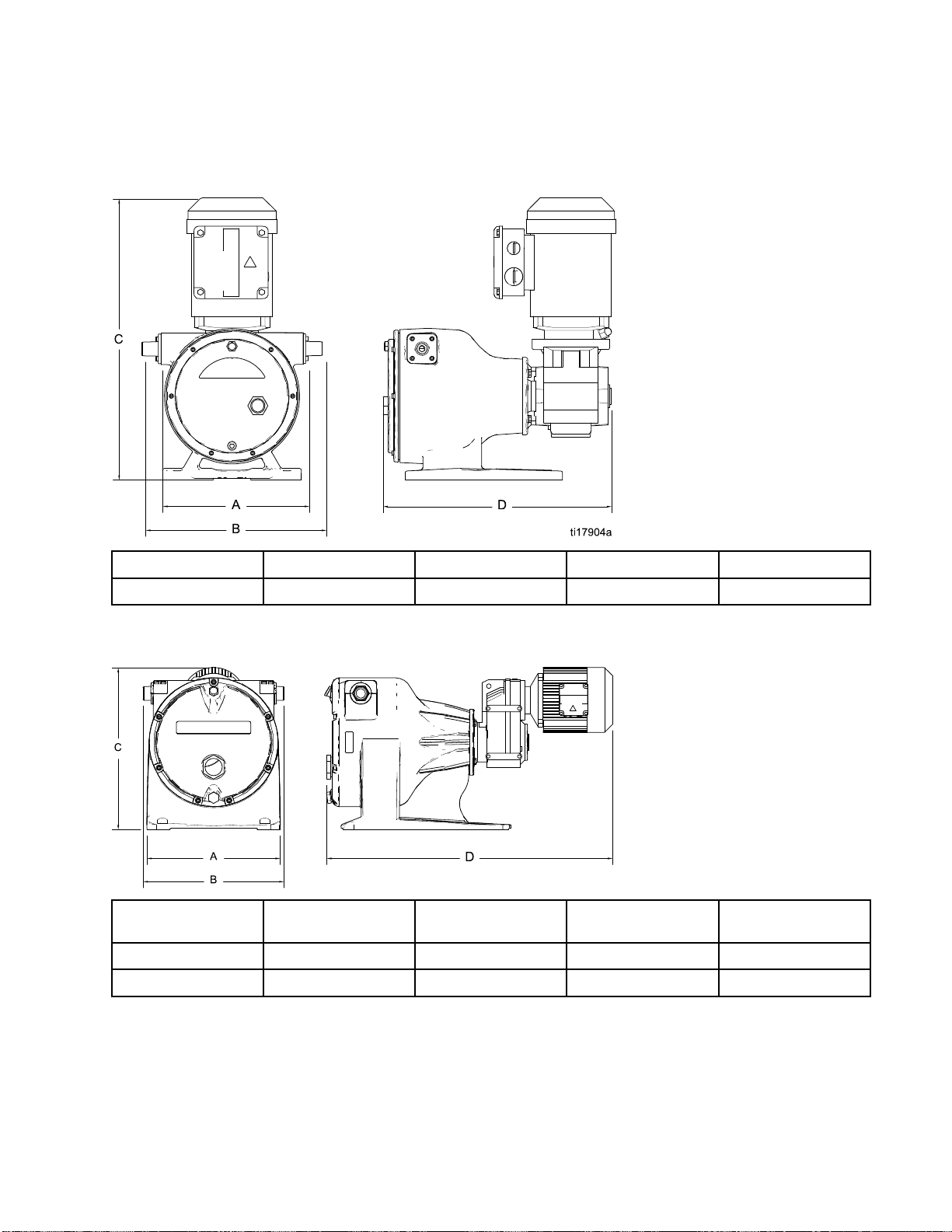
Dimensions
EP2 Hose Pumps
Dimensions
Model
EP2
EP3 and EP4 Hose Pumps
Pump Model
EP3
EP4
A, mm (in
228 (8.98) 280 (11.02) 437 (17.20) 339 (13.35)
A, mm (in.) B, mm (in.) C, mm (in.) D, mm (in.)
300
404 (15.91) 428 (16.86) 492 (19.35) 868 (34.15)
.)
(11.81)
B, mm (in
(13.52)
344
.)
C, mm (in
423
(16.65)
.)
D, mm (in
696
.)
(27.39)
3A1938E
21
Page 22
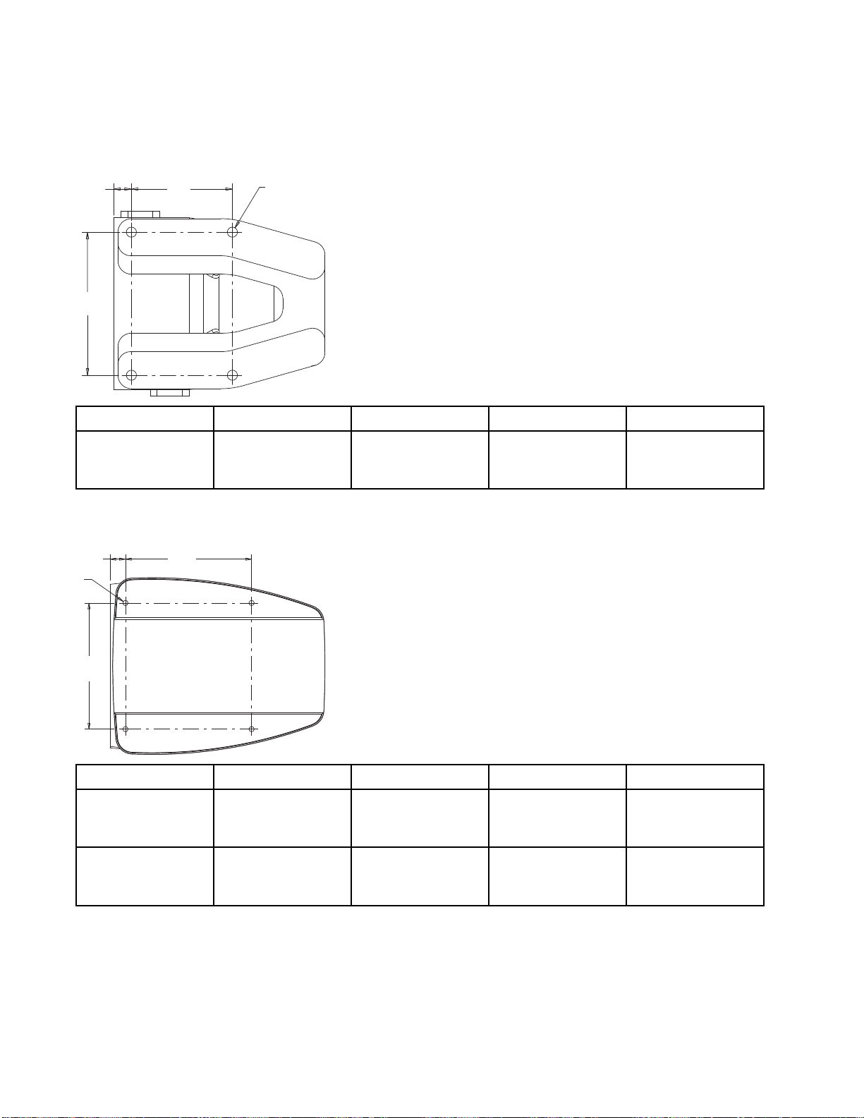
Mounting Hole La
youts
Mounting Hole Layouts
EP2 Hose Pumps
C
B
A
D
Pump Model A B
EP2
EP3 and E
C
D
B
120 mm (4.
P4 Hose Pumps
A
7in.)
Pump Model A B
EP3
229 mm (9 in.) 229 mm (9 in.) 28 mm (1.1 in.) Four 9.5 mm (0.37
170 mm (6.
7in.)
C
21 mm (0.8
C
3in.)
D
Four 12 mm
in.) diam
mountin
(0.47
eter
g holes
D
in.) diameter
mounting holes
EP4
2
2
0mm(12.2in.)
31
0mm(12.2in.)
31
mm (1.65 in.)
42
ur 9.5 mm (0.37
Fo
.) diameter
in
unting holes
mo
3A1938E
Page 23

Technical Data
EP2 Pumps
U.S.
Technical Data
Metric
Maximum Flui
Motor Horse
Maximum P
Maximum Environmental
Temperature
Minimum Environmental
Temperature
Maximum
EP2006 Pump 0.14 gpm 0.5 lpm
EP2013 Pump 0.80 gpm 3.0 lpm
Fluid Capacity per Revolution
EP200
EP2013 Pump 0.016 gal. 0.06 liters
Hose Inner Diameter
EP20
EP2013 Pump 13 mm
Noise
Sound Pressure Less than 80 dB(A)
Dim
Height 17.20 in. 437 mm
Width with hose installed 11.02 in. 280 mm
6Pump
06 Pump
ensions
d Working Pressure
power/Gear Ratio
ump Speed
Flow
125 psi 0.9 MPa, 9 bar
See the EP2 P
6 mm: 35 RPM; 13 mm: 50 RPM
122°F 50°C
14°F –10°C
gal.
0.004
ump Repair-Parts manual for the motor/gear
ratiousedo
n your pump:
0.5/51.30
0.75/35.10
0.33/157.
6mm
43
0.015
liters
Width without hose installed 8.98 in. 228 mm
Length 13.35 in. 339 mm
Weight 51.7 lb 23.5 kg
Fluid Inlet and Outlet Size 1/2 npt(m)
Wetted Parts
Pump Powder coated aluminum.
Hose
Barbed Fitting
See the Parts Matrix in the EP2 Pump Repair-Parts manual.
Stainless steel or Hastelloy. See the Parts Matrix in the EP2 Pump
Repair-Parts manual.
3A1938E 23
Page 24

Technical Data
EP3 Pumps
U.S.
Maximum Fluid Working Pressure 125 psi 0.9 MPa, 9 bar
Motor Horsepower/Gear Ratio
Maximum Pum
Maximum Environmental
Temperature
Minimum Environmental
Temperature
Maximum F
EP3019 Pump 2.4 gpm 9.1 lpm
Fluid Capacity per Revolution
EP3019 Pump 0.048 gal. 0.18 liters
Hose In
EP3019 Pump 19 mm
Noise
Sound Pressure Less than 80 dB(A)
Dimen
Height 16.65 in. 423 mm
Width with hose installed 13.52 in. 344 mm
Widt
Length 27.39 in. 696 mm
Weight 142.7 lb 64.9 kg
Fluid Inlet and Outlet Size 3/4 npt(m)
We
Pump Powder coated aluminum.
Hose
Barbed Fitting
ner Diameter
sions
h without hose installed
tted Parts
p Speed
low
See the EP3 Pump Repair-Parts manual for the motor/gear
ratio used on your pump:
1.5/35.91
1.0/100.36
50 RPM
122°F 50°C
14°F –10°C
1in.
11.8
See the Parts Matrix in the EP3 Pump Repair-Parts manual.
Stainless steel or Hastelloy. See the Parts Matrix in the EP3 Pump
Repair-Parts manual.
Metric
300 m
m
4
2
3A1938E
Page 25

Technical Data
EP4 Pumps
U.S.
Maximum Fluid Working Pressure 125 psi 0.9 MPa, 9 bar
Motor Horsepower/Gear Ratio
Maximum Pump Speed
See the EP4 Pump Repair-Parts manual for the motor/gear
ratiousedonyourpump:
2.0/19.70
2.0/34.29
2.0/79.72
130 RPM
Metric
Maximum Environmental
Temperature
Minimum Environmental
Temperature
Maximum Flow
EP4029 Pump 19.5 gpm 73.8 lpm
Fluid Capacity per Revolution
EP4029 Pump 0.15 gal. 0.56 liters
Hose Inner Diameter
EP4029 Pump 29 mm
Noise
Sound Pressure Less than 80 dB(A)
Dimensions
Height 19.35 in. 492 mm
Width with hose installed 16.86 in. 428 mm
Width without hose installed 15.91 in. 404 mm
Length 34.15 in. 868 mm
Weight 252 lb 114.5 kg
Fluid Inlet and Outlet Size 1–1/4 npt(m)
Wetted Parts
Pump Powder coated aluminum.
Hose
Barbed Fitting
See the Parts Matrix in the EP4 Pump Repair-Parts manual.
Stainless steel or Hastelloy. See the Parts Matrix in the EP4 Pump
Repair-Parts manual.
122°F 50°C
14°F –10°C
3A1938E 25
Page 26

Performance Dat
a
Performance D
EP2006 Hose Pump
0.75
0.50
Flow (gpm)
0.25
0.00
0 20 40 60 80 100 120
Pump Speed (rpm)
ata
EP2013 Hose Pump
2.5
2.0
1.5
Flow (gpm)
1.0
0.5
0.0
0 20 40 60 80 100 120
Pump Speed (rpm)
26 3A1938E
Page 27

Performance Dat
a
EP3019 Hose Pump
7
6
5
4
3
Flow (gpm)
2
1
0
0 20 40 60 80 100 120
Pump Speed (rpm)
EP4029 Hose Pump
20
18
16
14
12
10
Flow (gpm)
8
6
4
2
0
0 20 40 60 80 100 120
Pump Speed (rpm)
3A1938E
27
Page 28

Graco Standard Warranty
Graco warrants all equipment referenced in this document which is manufactured by Graco and bearing its
name to be free from defects in material and workmanship on the date of sale to the original purchaser for
use. With the exception of any special, extended, or limited warranty published by Graco, Graco will, for a
period of twelve months from the date of sale, repair or replace any part of the equipment determined
by Graco to be defective. This warranty applies only when the equipment is installed, operated and
maintained in accordance with Graco’s written recommendations.
This warranty does not cover, and Graco shall not be liable for general wear and tear, or any malfunction,
damage or wear caused by faulty installation, misapplication, abrasion, corros
maintenance, negligence, accident, tampering, or substitution of non-Graco component parts. Nor shall
Graco be liable for malfunction, damage or wear caused by the incompatibility of Graco equipment
with structures, accessories, equipment or materials not supplied by Graco, o
manufacture, installation, operation or maintenance of structures, accessories, equipment or materials
not supplied by Graco.
This warranty is conditioned upon t
authorized Graco distributor for verification of the claimed defect. If the claimed defect is verified, Graco
will repair or replace free of charge any defective parts. The equipment will be returned to the original
purchaser transportation prepaid. If inspection of the equipment does not disclose any defect in material
or workmanship, repairs will be m
parts, labor, and transportati
THIS WARRANTY IS EXCLUSIVE, AND IS IN LIEU OF ANY OTHER WARRANTIES, EXPRESS OR
IMPLIED, INCLUDING BUT NOT LIMITED TO WARRANTY OF MERCHANTABILITY OR WARRANTY
OF FITNESS FOR A PARTICULAR PURPOSE.
Graco’s sole obligation and buyer’s sole remedy for any breach of warranty shall be as set forth above.
The buyer agrees that no other remedy (including, but not limited to, incidental or consequential damages
for lost profits, lost sales, injury to person or property, or any other incidental or consequential loss) shall
be available. Any action for breach of warranty must be brought within two (2) years of the date of sale.
GRACO MAKES NO WARRANTY, AND DISCLAIMS ALL IMPLIED WARRANTIES OF
MERCHANTABILITY AND FITNESS FOR A PARTICULAR PURPOSE, IN CONNECTION WITH
ACCESSORIES, EQUIPMENT, MATERIALS OR COMPONENTS SOLD BUT NOT MANUFACTURED BY
GRACO. These items sold, but not manufactured by Graco (such as electric motors, switches, hose, etc.),
are subject to the warranty, if any, of their manufacturer. Graco will provide purchaser with reasonable
assistance in making any claim for breach of these warranties.
In no event will Graco be liable for indirect, incidental, special or consequential damages resulting from
Graco supplying equipment hereunder, or the furnishing, performance, or use of any products or other
goods sold hereto, whether due to a breach of contract, breach of warranty, the negligence of Graco, or
otherwise.
FOR GRACO CANADA CUSTOMERS
The Parties acknowledge that they have required that the present document, as well as all documents,
notices and legal proceedings entered into, given or instituted pursuant hereto or relating directly or
indirectly hereto, be drawn up in English. Les parties reconnaissent avoir convenu que la rédaction du
présente document sera en Anglais, ainsi que tous documents, avis et procédures judiciaires exécutés,
donnés ou intentés, à la suite de ou en rapport, directement ou indirectement, avec les procédures
concernées.
he prepaid return of the equipment claimed to be defective to an
ade at a reasonable charge, which charges may include the costs of
on.
ion, inadequate or improper
r the improper design,
Graco Information
To place an order, contact your Graco Distributor or call to identify the nearest distributor.
Phone: 612-623-6921 or Toll Free: 1-800-328-0211 Fax: 612-378-3505
All written and visual data contained in this document reflects the latest product information available at the time of publication.
GRACO INC. AND SUBSIDIARIES • P.O. BOX 1441 • MINNEAPOLIS, MN 55440-1441 • USA
Copyright 2011, Graco Inc. All Graco manufacturing locations are registered to ISO 9001.
Graco reserves the right to make changes at any time without notice.
Original Instructions. This manual contains English, MM 3A1938
Graco Headquarters: Minneapolis
International Offices: Belgium, China, Japan, Korea
www.graco.com
Revision E, June 2014
 Loading...