

Page 1
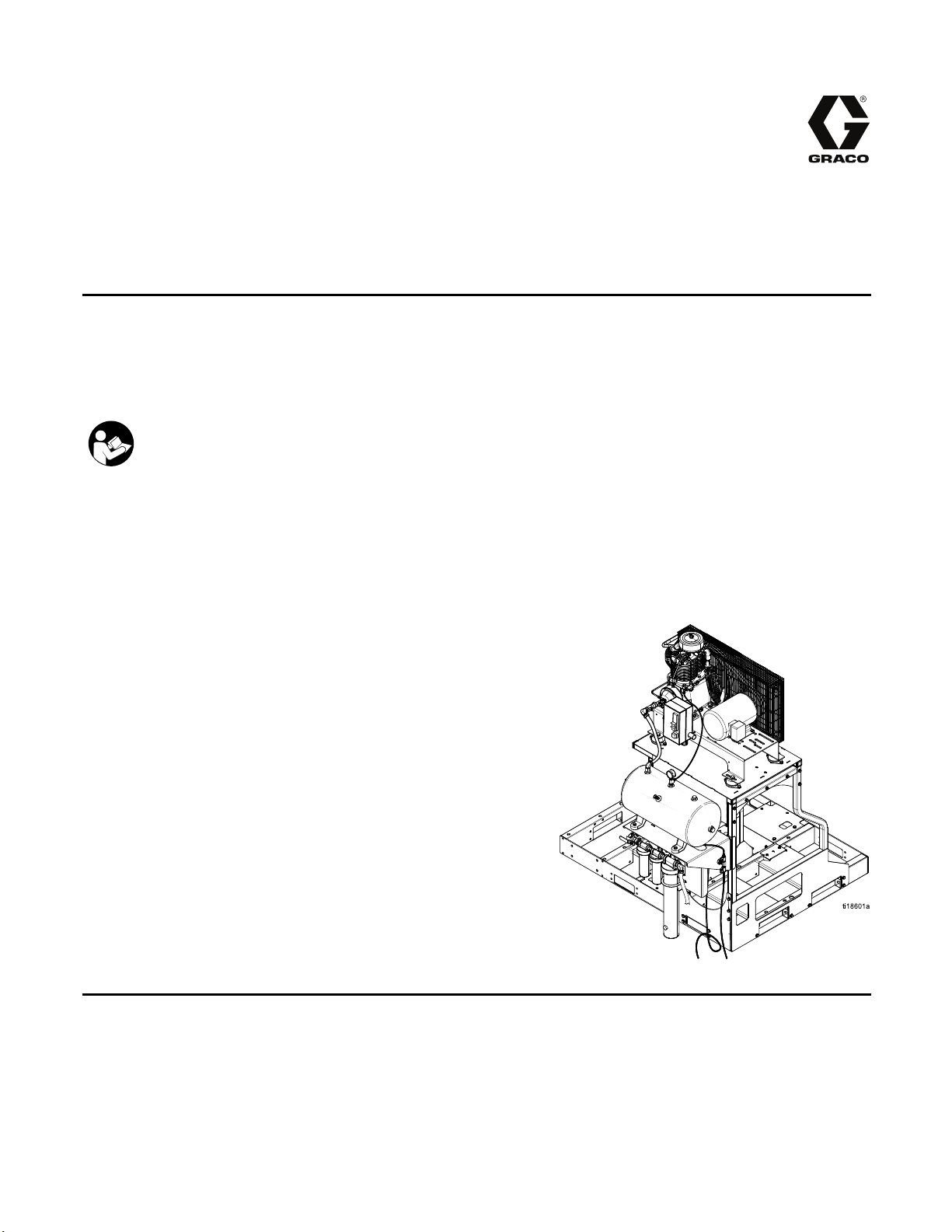
Instructions-Parts
Air Compressor Kit
Air compressor and receiver tank for Reactor® E-30i and E-XP2i integrated plural component
proportioning systems. For professional outdoor use only. Not for use in explosive atmospheres.
Important Safety Instructions
Read all warnings and instructions in this manual. Save these
instructions.
24K335
3A1902C
EN
PROVEN QUALITY. LEADING TECHNOLOGY.
Page 2
Contents
Install Air Co
Install Air Tank ................................................... 3
Connect Air Lines ............................................... 3
mpressor......................................... 2
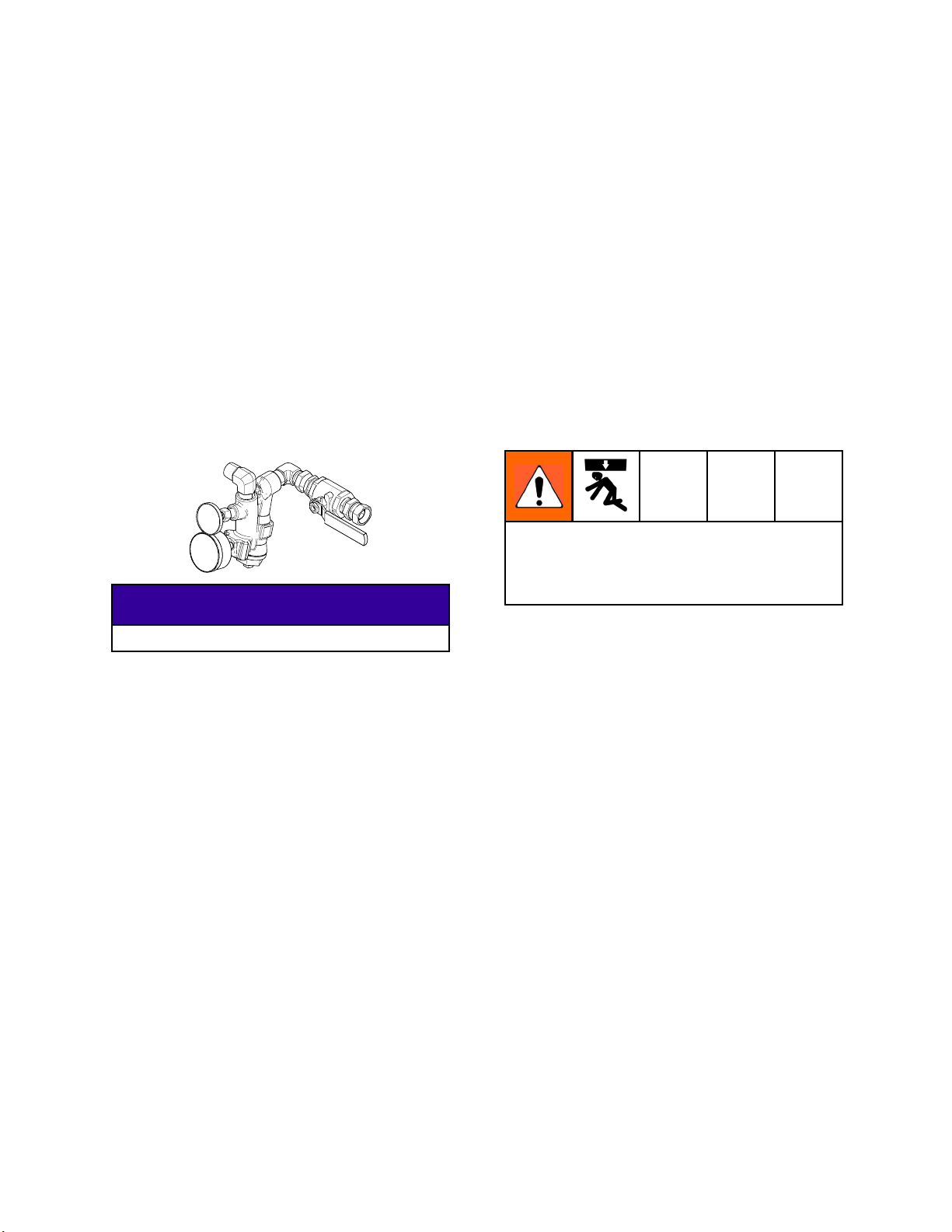
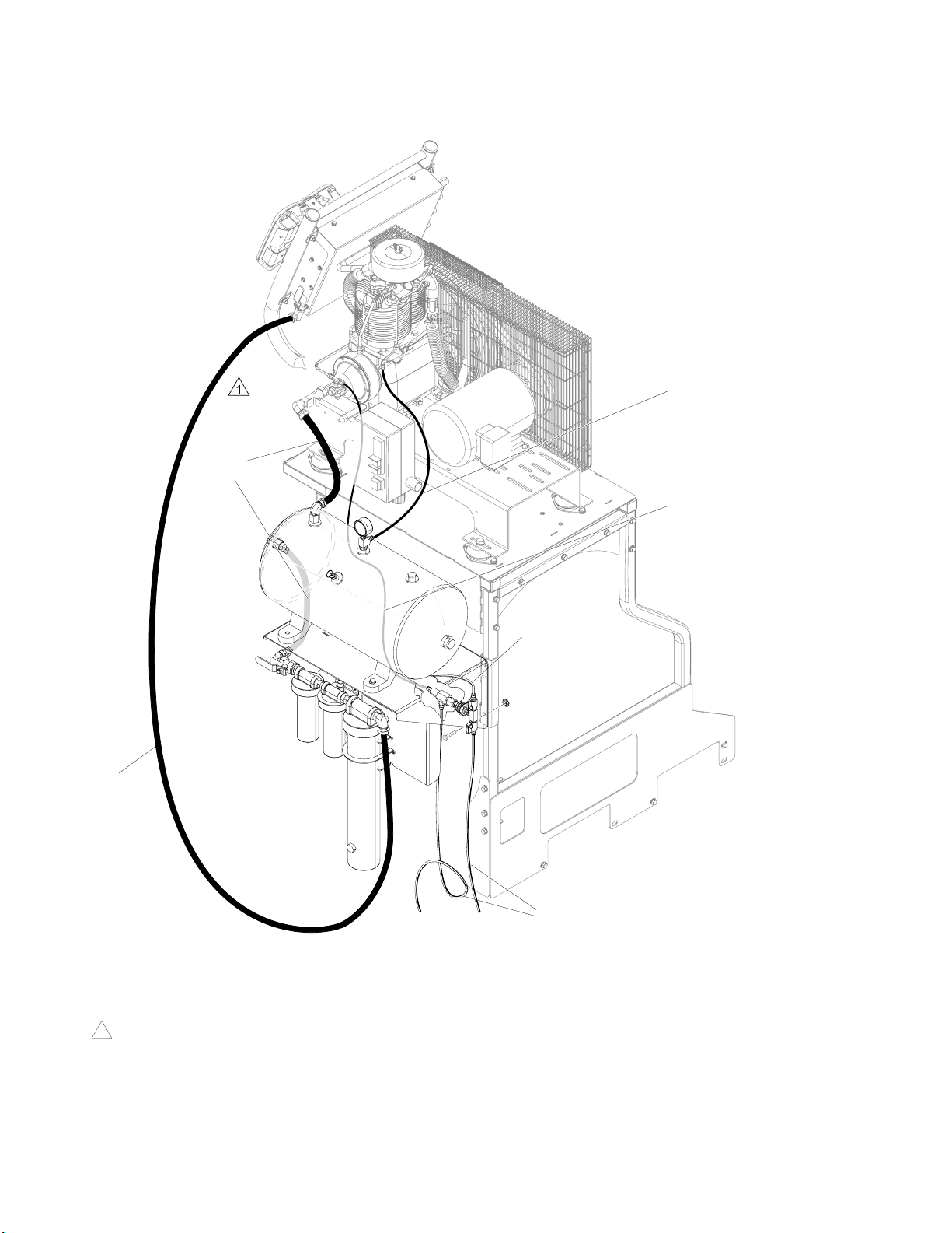
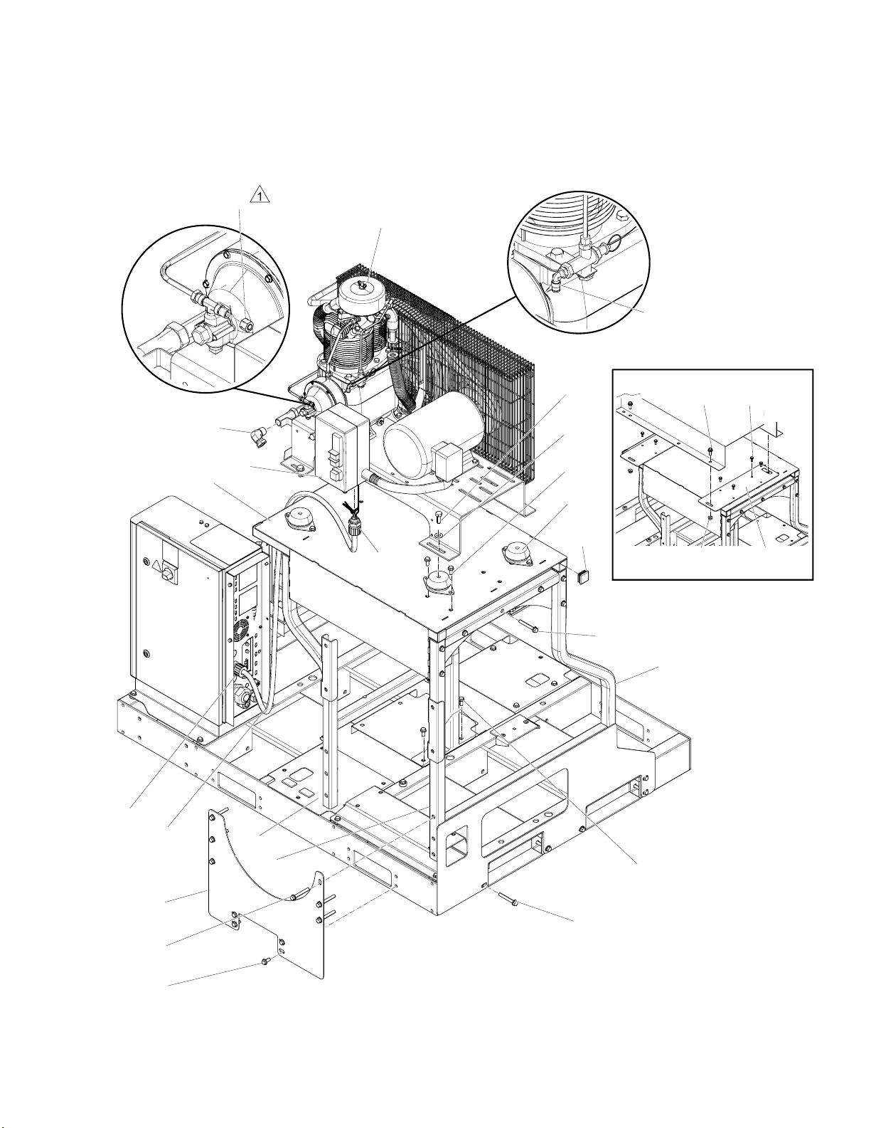
Install Air Compressor
Reference
1. Remove the battery bracket and fuel tank. See
system repair manual for instructions.
2. Turn the B side y-strainer inlet on the Reactor
as shown.
parts illustration, Parts, page 7 .
NOTICE
Connect Power
Parts.................................................................. 7
Graco Standard Warranty.................................... 10
8. Lift side o
level bef
nuts.
9. Install f
plate ass
Use lifting device to prevent personal injury
when lifting the compressor. Do not overlap
lifting straps over tubing or other fragile
components.
Cable ......................................... 5
f gusset (5) to ensure top plate (3) is
ore tightening. Tighten all screws and
our isolators (8) with screws (10) on top
embly (3).
Be careful to not damage engine components.
3. Loosely assemble the front bracket (2) to pallet
using two screws (10).
4. Install the side support gusset (5) to the pallet
with four screws (10) and nuts (11) as shown. Do
not tighten the screws.
5. Install the rear bracket (1) on the pallet with five
screws (9) and nuts (11). Do not tighten the
screws.
6. Install the six screws (10) and nuts (11) through
the top of the support gusset (5). Do not tighten
the screws.
7. Assemble the top plate assembly (3) to frame
with 14 screws (9) and nuts (11). Do not tighten
the screws.
10. Lift the air compressor (7) onto the isolators (8).
Secure the air compressor to the isolators with
four screws (28), washers (29).
11. Install elbow adapter (13) in air compressor
outlet.
12. Remove plug and install elbow fitting (41) on
compressor pilot valve (see parts illustration).
13. Remove compression nut cap and install
compression nut fitting (37). Tighten finger tight
only.
14. Install end caps (32).
2
3A1902C
Page 3

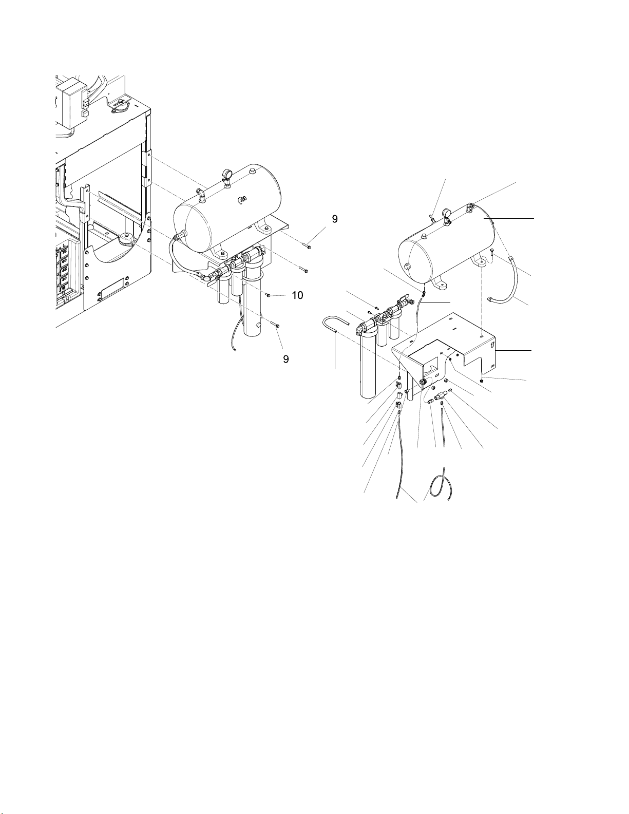
Install Air Tank
Install Air Tank
Reference parts illustration, Parts, page 8.
1. Connect nippl
connector (15
(30). Apply P
2. Install bulk
3. Install bush
and two conne
PTFE sealan
4. Install con
5. Remove desi
desiccant
Drying Sys
6. Connect ai
with screw
7. Mount tan
and nuts (
compress
screw (10
e (26), water drain valve (16),
), and connector (31) to bulkhead
TFE sealant on threads.
head assembly to bracket wall (6).
ing (47), tee (48), two ball valves (17),
ctors (15) to bulkhead (30). Apply
t on threads.
nector elbow (41) to bottom of tank (4).
ccant housing and fill with all
pellets provided. See Desiccant Air
tem manual 309921.
r dryer assembly (33) to bracket (6)
s (39), nuts (40), and clamp (38).
k (4) on bracket (6) with screws (12)
11). Mount bracket assembly to the
or frame with three screws (9), one
), and four nuts (11).
Connect Air Lines
Reference Fig
1. Cut tube (36) to the following lengths (see next
page):
a. Three – 48 in (1219 mm)
b. 9 in. (228.6 mm)
c. 25 in. (635 mm)
2. Push one end of a 48 in. (1219 mm) section fully
into compression fitting (37). Tighten 3/4 turn
past finger tight.
3. Push all tubing sections fully into push-to-connect
fittingsasshown.
4. Connect air hoses (23) and (24) as shown.
. 1, page 4.
3A1902C 3
Page 4
Connect Air Line
s
Connect all air hoses as shown.
24
24
36
25 in. (635 mm)
36
48 in.
(1219 mm)
23
Air Hose Connections
Figure 1
Tighten compression nut 3/4 turn past finger
1
tight.
36
9 in. (228.6 mm)
36
36
48 in.
(1219 mm)
ti18580a
4
3A1902C
Page 5
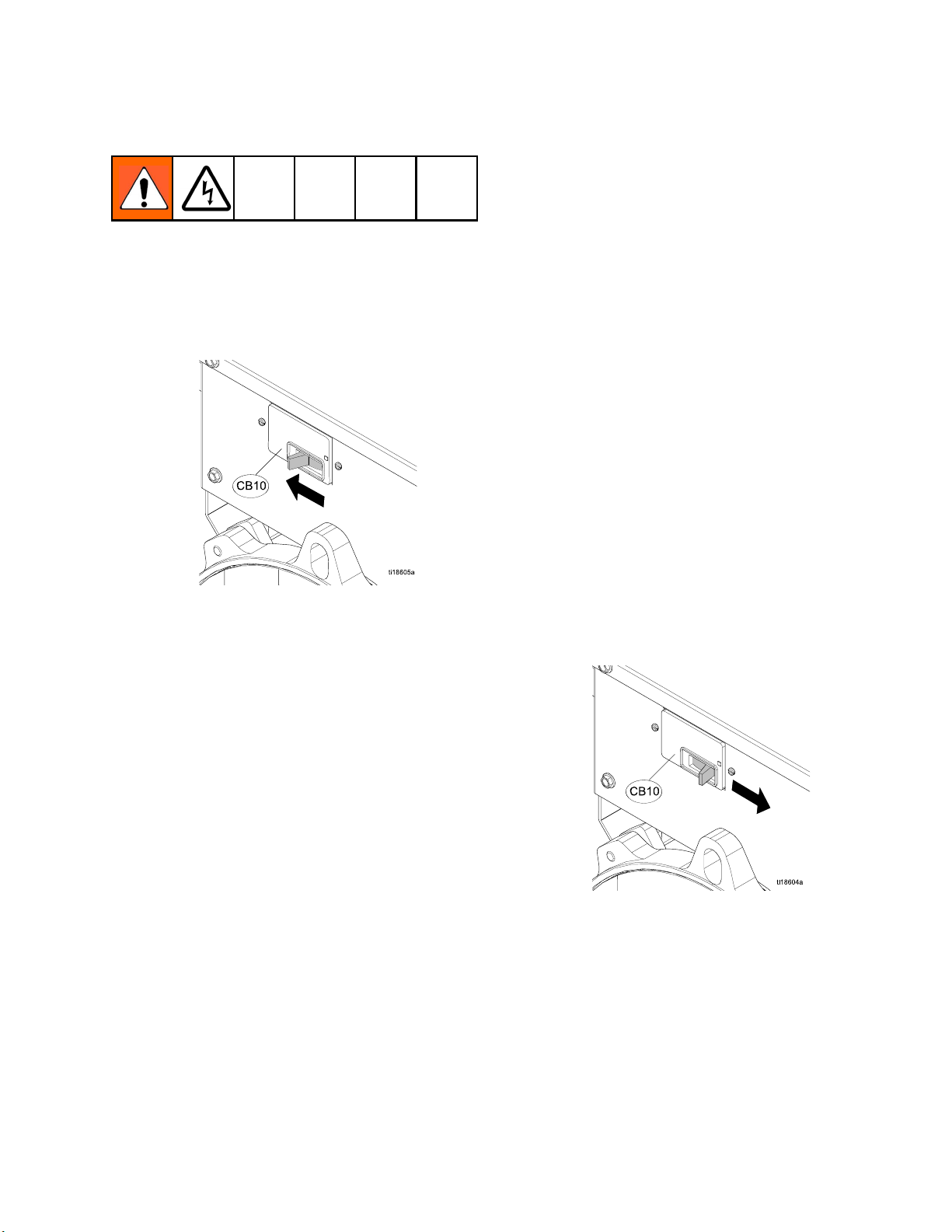
Connect Power Cable
Connect Power Ca
ble
Note
Reference wiring diagram. See
Fig. 4, page 6.
1. Turn off the 120/240 VAC alternator circuit
breaker (CB10).
Figure 2
2. Loosen screw, below the air compressor
electrical enclosure (E), 1/4 turn until the cover is
loose. Remove cover.
3. Discard washer on the cord grip (35). Install
cord grip up through the bottom of the enclosure
knockout. Tighten cord grip mounting nut inside
the enclosure.
7. Tighten the bottom nut on the cord grip (35).
8. Replace cover. See Fig. 4, page 5.
9. Loosen the bolts and remove the back panel of
the Reactor electrical enclosure.
10. Use a screw driver to punch out a knockout.
11. Discard washer from cord grip (35). Install cord
grip through back panel.
12. Loosen the nut on the cord grip (35). Insert the
free end of the power cord (34) through the cord
grip.
13. Connect the black and white wire to CB04,
see Fig. 4, page 5. Connect the green wire to
the ground bus bar, GB02 inside the Reactor
electrical enclosure.
14. Tighten nut on the cord grip (35).
15. TurnCB04on. SeeFig. 4,page5.
16. Turn on the 120/240 VAC alternator circuit
breaker (CB10).
4. Loosen the outside nut on the cord grip (35).
Insert the end of the power cable (34) with shorter
strip lengths through the cord grip.
5. Connect the black wire to terminal 1/L1 and the
white wire to 3/L2.
6. Loosen ground screw and connect ground wire
with existing ground wire.
Figure 3
3A1902C 5
Page 6

Connect Power Ca
ELECTRICAL ENCLOSURE BOUNDARY
CIRCUIT BREAKER
ASS’Y, 24J728
TB18
{
GND
TB17
TB16
L2
{
TB15
TB14
L1
{
TB13
ble
AIR COMPRESSOR ELECTRICAL ENCLOSURE
WHT
BLK
1/L1
2/T1 4/T2 6/T3
BLK
3/L2 5/L3
BLK
WHT
BLK
CB01 CB0 2 CB03 CB04 CB05 CB06 CB0 7 CB0 8TB12TB11
POWER CABLE, 16M827
CT02
CORD GRIP,
16M826
GRN
GB02
Ground Bar
122313
BLK
BLK
GRN
GRN
CORD GRIP,
16M826
TO AIR
COMPRESSOR
Air Compressor Wiring Diagram
Figure 4
6 3A1902C
Page 7
Parts
24K335, Complete Air Compressor Kit
37
7
Parts
41
13
3
28
29
E
35
10
8
32
9
44
45
2
10
46
35
34
5
9
10
Apply anaerobic sealant to all non-swivel pipe threads.
3A1902C
2
1
ti18539b
10
9
7
Page 8
Parts
39
33
38
15
17
48
17
41
47
30
26
4a
36
15
38
4b
4
12
24
6
11
40
31
16
ti18540b
15
Apply anaerobic sealant to all non-swivel pipe threads.
36
8 3A1902C
Page 9

Parts
Part Description
Ref
24M147
1*
24M146
2*
24M145
3*
424M125
4a 125967
4b 16N185
16K133
5*
24M150
6*
7
125970
8 125165
121488
9*
111192
10*
112958
11*
12 112785
13 120375 ADAPTER, elbow, 3/4–14
15 125428
16 125991 VALVE, drain, automatic 1
17 15B565 VALVE, ball 2
23 214656
24 218
26 297436
093
RACK, compressor, rear
RACK, compressor, front
RACK, compressor, top
TANK, ASM, 12 gal, air
receiver (includes 4a and
4b)
VALVE, safet
psi (1.4 MPa
VALVE, check, 1/2 m x f
GUSSET, compressor,
support, side
BRACKET, air tank/dryer
COMPRESSOR, air, 5 HP
KIT, isolator (4 pack)
SCREW, hex hd, flanged;
2.75 in. (70 mm), 3/8–16
SCREW, c
.875 in.
NUT, hex, flanged; 3/8–16
SCREW, hex hd, flanged;
1.5in. (38mm),3/8–16
NPT (f)X 1/2–14 NPS (m)
CONNECTOR, male, 1/4
NPT (f)
, coupled, 61209,10
HOSE
3m)
ft (
HOSE, coupled; 1/2–14
NPT
STRAIGHT, nipple, hex.
3/8
y relief, 200
,14bar)
ap flange hd;
(22 mm), 3/8–16
Qty
1
1
1
1
1
1
1
1
1
4
28
15
4
4
1
3
1
2
1
Part Description
Ref
28 105324
29 109570
30 16N177 BULKHEAD, brass, 3/8 1
31 115671
111218
32*
33 24M636
34 16M827
35 16M826
36 24M675 KIT, tube, nylon, rd; 1/4 in.
37 16M960 NUT, compression, with
38 126017
39 113796
40 115942
41 114109
111195
44*
112731
45*
16N1
46*
47 126109
48 126110
SCREW, cap, hex hd; 1.18
in. (30 mm), M12 x 1.75
WASHER, plain
CONNECTOR, m
OD x 1/8 NPT (f
CAP, tube, square
SYSTEM, desiccant air
dryer; see manual 309921
HARNESS, wire, 3 pole, 8/3
CORD, grip, 3/4 in.
OD,16ft(4.8m)
sleeve; 1/4 OD
BOLT,U,1/2-13,4ODpipe
SCREW, flanged, hex hd;
0.75 in. (19 mm), 1/4–20
NUT, hex
1/4–20
ELBOW, male, swivel; 1/4
OD, 1/4 NPT (f)
SCREW, cap, flange hd;
1.25 in. (31.75 mm), 1/2–13
NUT,
65
PLAT
adap
FITTING, bushing adapter,
3/8–18 NPT (m) x 1/4–18
NPT (f)
TTING, tee, male branch,
FI
4–18 NPT
1/
, flange head;
hex, flanged; 1/2–13
E, compressor,
ter
ale; 1/4
)
Qty
4
4
1
4
1
1
2
1
1
1
2
2
2
4
2
2
1
1
cluded in Compressor Frame Kit 24M258.
*
In
Parts for adapting to the mounting feet of the
optional Quincy PTL5–5B air compressor.
See Fig. 1, page 3 for Air Hose Connections.
3A1902C 9
Page 10

Graco Standard Warranty
Graco warrants all equipment referenced in this document which is manufactured by Graco and bearing its
name to be free from defects in material and workmanship on the date of sale to the original purchaser for use.
With the exception of any special, extended, or limited warranty published by Graco, Graco will, for a period of
twelve mont
defective. This warranty applies only when the equipment is installed, operated and maintained in accordance
with Graco’s written recommendations.
This warranty does not cover, and Graco shall not be liable for general wear and tear, or any malfunction,
damage or wear caused by faulty installation, misapplication, abrasion, corrosion, inadequate or improper
maintenance, negligence, accident, tampering, or substitution of non-Graco component parts. Nor shall Graco
be liable for malfunction, damage or wear caused by the incompatibility of Graco equipment with structures,
accessories, equipment or materials not supplied by Graco, or the improper design, manufacture, installation,
ation or maintenance of structures, accessories, equipment or materials not supplied by Graco.
oper
This warranty is conditioned upon the prepaid return of the equipment claimed to be defective to an authorized
Graco distributor for verification of the claimed defect. If the claimed defect is verified, Graco will repair or replace
free of charge any defective parts. The equipment will be returned to the original purchaser transportation
prepaid. If inspection of the equipment does not disclose any defect in material or workmanship, repairs will be
made at a reasonable charge, which charges may include the costs of parts, labor, and transportation.
THIS WARRANTY IS EXCLUSIVE, AND IS IN LIEU OF ANY OTHER WARRANTIES, EXPRESS OR IMPLIED,
INCLUDING BUT NOT LIMITED TO WARRANTY OF MERCHANTABILITY OR WARRANTY OF FITNESS
FOR A PARTICULAR PURPOSE.
Graco’s sole obligation and buyer’s sole remedy for any breach of warranty shall be as set forth above. The
buyer agrees that no other remedy (including, but not limited to, incidental or consequential damages for lost
profits, lost sales, injury to person or property, or any other incidental or consequential loss) shall be available.
Any action for breach of warranty must be brought within two (2) years of the date of sale.
GRACO MAKES NO WARRANTY, AND DISCLAIMS ALL IMPLIED WARRANTIES OF MERCHANTABILITY
AND FITNESS FOR A PARTICULAR PURPOSE, IN CONNECTION WITH ACCESSORIES, EQUIPMENT,
MATERIALS OR COMPONENTS SOLD BUT NOT MANUFACTURED BY GRACO. These items sold, but not
manufactured by Graco (such as electric motors, switches, hose, etc.), are subject to the warranty, if any, of
their manufacturer. Graco will provide purchaser with reasonable assistance in making any claim for breach of
these warranties.
In no event will Graco be liable for indirect, incidental, special or consequential damages resulting from Graco
supplying equipment hereunder, or the furnishing, performance, or use of any products or other goods sold
hereto, whether due to a breach of contract, breach of warranty, the negligence of Graco, or otherwise.
FOR GRACO CANADA CUSTOMERS
The Parties acknowledge that they have required that the present document, as well as all documents, notices
and legal proceedings entered into, given or instituted pursuant hereto or relating directly or indirectly hereto, be
drawn up in English. Les parties reconnaissent avoir convenu que la rédaction du présente document sera en
Anglais, ainsi que tous documents, avis et procédures judiciaires exécutés, donnés ou intentés, à la suite de ou
en rapport, directement ou indirectement, avec les procédures concernées.
hs from the date of sale, repair or replace any part of the equipment determined by Graco to be
Graco Information
For the latest information about Graco products, visit www.graco.com.
To place an order, contact your Graco Distributor or call to identify the nearest distributor.
Phone: 612-623-6921 or Toll Free: 1-800-328-0211 Fax: 612-378-3505
All written and visual data contained in this document reflects the latest product information available at the time of publication.
Graco reserves the right to make changes at any time without notice.
For patent information, see www.graco.com/patents.
Original Instructions. This manual contains English. MM 3A1902
Graco Headquarters: Minneapolis
International Offices: Belgium, China, Japan, Korea
GRACO INC. AND SUBSIDIARIES • P.O. BOX 1441 • MINNEAPOLIS MN 55440-1441 • USA
Copyright 2012, Graco Inc. All Graco manufacturing locations are registered to ISO 9001.
www.graco.com
Revised 28 June 2012
 Loading...