

Page 1
Operation
3A1705J
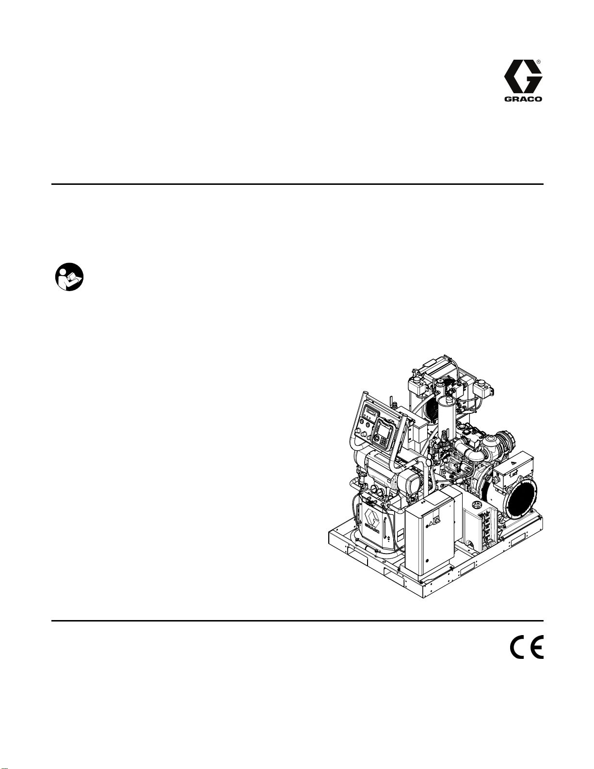
Reactor® E-30i and E-XP2i
Electric, Heated, Integrated Plural Component Proportioning System With Integrated Generator. For
spraying polyurethane foam and polyurea coatings. For professional use only. Not approved for use in
explosive atmospheres or hazardous locations.
Important Safety Instructions
Read all warnings and instructions in this manual. Save these
instructions.
EN
PROVEN QUALITY. LEADING TECHNOLOGY.
Page 2

Contents
Warnings ............................................................. 3
Important Two-Component Material
Information ............................................. 7
Proportioner Models ............................................. 9
Systems............................................................. 10
Accessories........................................................ 11
Supplied Manuals............................................... 12
Related Man
Typical Installation, with circulation ...................... 13
Typical Installation, without circulation.................. 14
Component
Generator
Proportio
Air Compr
Advanced
Motor Con
Engine Co
Load Cen
Tempera
Circuit
Overview............................................................ 30
Setup................................................................. 33
Locate Reactor ............................................ 33
Trailer Setup Guidelines............................... 35
Install Wall (optional).................................... 36
Connect Battery........................................... 38
Add Fuel ..................................................... 38
General Equipment Guidelines ..................... 38
Electrical Connections.................................. 39
Connect Feed Pumps................................... 39
Breathing Air................................................ 39
Connect Pressure Relief Lines...................... 40
Install Fluid Temperature Sensor .................. 40
Connect Heated Hose.................................. 40
Close gun fluid manifold valves A and
Connect Whip Hose to Gun Or Gun Fluid
Pressure Check Hose .................................. 41
Connect Remote Display Module .................. 41
Grounding ................................................... 41
Supply Wet Cups With Throat Seal Liquid
vanced Display Module (ADM)
Ad
uals ................................................ 12
Identification..................................... 15
.................................................... 17
ner Control Panel ........................... 18
essor............................................ 18
Display Module (ADM).................. 19
trol Module (MCM)........................ 23
ntrol Module ................................. 24
ter ................................................ 25
ture Control Modules....................... 26
Breakers ........................................... 28
B ................................................... 41
Manifold......................................... 41
(TSL) ............................................. 42
eration.............................................. 43
Op
Advanced Setu
System........................................................ 47
Recipes....................................................... 47
Run Mode ................................................... 48
Startup............................................................... 55
Temporary Manual Hose Temperature
Control ................................................. 58
Fluid Circulation.................................................. 59
Circulation Through Reactor ......................... 59
Circulation Through Gun Manifold................. 60
Jog Mode........................................................... 60
Spraying ............................................................ 61
Spray Adjustments....................................... 62
Shutdown........................................................... 63
Pressure Relief Procedure .................................. 64
Flushing............................................................. 65
Maintenance ...................................................... 66
Preventative Maintenance Schedule ............. 66
Proportioner Maintenance ............................ 66
Engine Maintenance .................................... 67
Fuel Tank .................................................... 67
Flush Inlet Strainer Screen ........................... 67
Pump Lubrication System............................. 68
Drain Coolant .............................................. 69
Refill Proportioner Coolant Loop ................... 70
Refill Engine Coolant Loop ........................... 72
Coolant Specifications.................................. 72
Errors ................................................................ 73
View Errors.................................................. 73
Troubleshoot Errors ..................................... 73
Troubleshooting.................................................. 74
Error Codes and Troubleshooting.................. 74
USB Data........................................................... 89
USB Logs.................................................... 89
System Configuration Settings ...................... 90
Download Procedure.................................... 91
Custom Language File ................................. 91
Upload Procedure........................................ 92
Appendix A: Engine Control Module..................... 93
Dimensions........................................................ 96
Performance Charts............................................ 99
Technical Specifications.................................... 102
aco Standard Warranty.................................. 106
Gr
p Screens ............................. 46
2
3A1705J
Page 3
Warnings
Warnings
The following
exclamation p
risks. When th
hazard symbo
where applic
warnings are for the setup, use, grounding, maintenance and repair of this equipment. The
oint symbol alerts you to a general warning and the hazard symbol refers to procedure-specific
ese symbols appear in the body of this manual refer back to these Warnings. Product-specific
ls and warnings not covered in this section may appear throughout the body of this manual
able.
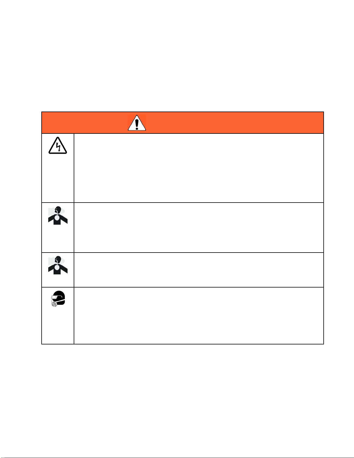
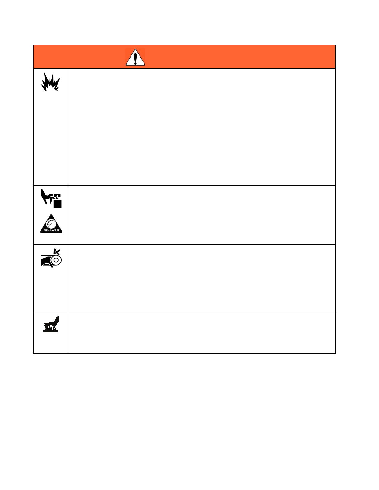
WARNING
ELECTRIC SHOCK HAZARD
This equip
cause elec
• Turn off and disconnect power at main switch before disconnecting any cables and before
servicing equipment.
• Connect o
• All electrical wiring must be done by a qualified electrician and comply with all local codes
and regulations.
TOXIC FLUID OR FUMES
Toxic fluids or fumes can cause serious injury or death if splashed in the eyesoronskin,
inhaled, or swallowed.
• Read MSDSs to know the specific hazards of the fluids you are using.
• Store hazardous fluid in approved containers, and dispose of it according to applicable
guidelines.
ment must be grounded. Improper grounding, setup, or usage of the system can
tric shock.
nly to grounded power source.
CARBO
Exhau
carbo
• Do not operate in an enclosed area.
PERS
You m
oper
hear
• Protective eyewear, and hearing protection.
•Res
N MONOXIDE HAZARD
st contains poisonous carbon monoxide, which is colorless and odorless. Breathing
n monoxide can cause death.
ONAL PROTECTIVE EQUIPMENT
ust wear appropriate protective equipment when operating, servicing, or when in the
ating area of the equipment to help protect you from serious injury, including eye injury,
ing loss, inhalation of toxic fumes, and burns. This equipment includes but is not limited to:
pirators, protective clothing, and gloves as recommended by the fluid and solvent
ufacturer.
man
3A1705J 3
Page 4
Warnings
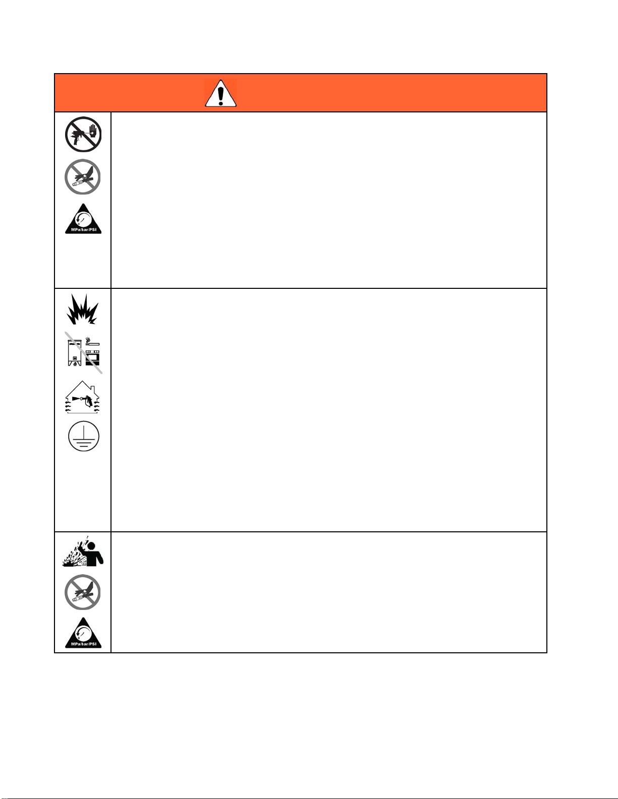
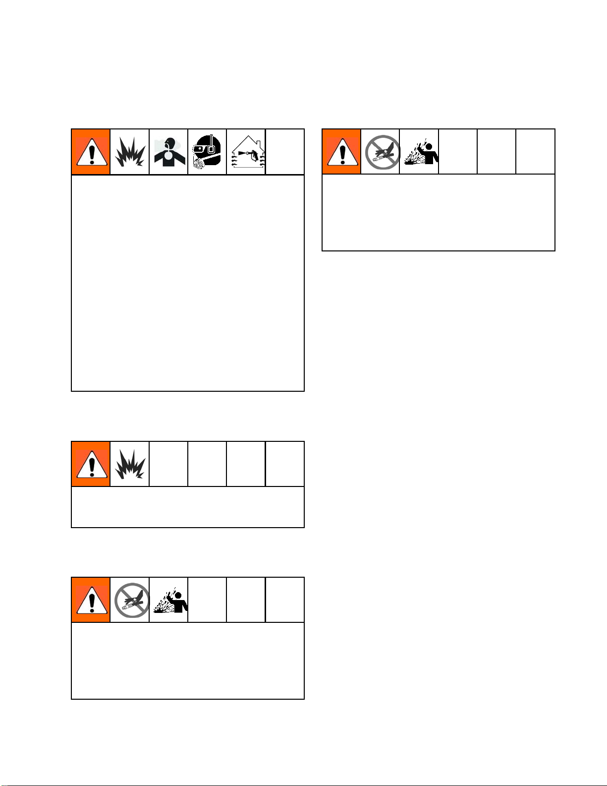
WARNING
SKIN INJECTION HAZARD
High-pressure fluid from dispensing device, hose leaks, or ruptured components will pierce
skin. This may look like just a cut, but it is a serious injury that can result in amputation. Get
immediate surgical treatment.
• Engage trigg
• Do not point dispensing device at anyone or at any part of the body.
• Do not put your hand over the fluid outlet.
• Do not stop o
• Follow the Pressure Relief Procedure when you stop dispensing and before cleaning,
checking, or servicing equipment.
• Tighten all fluid connections before operating the equipment.
• Check hose
FIRE AND EXPLOSION HAZARD
Flammabl
prevent fi
• Use equipment only in well ventilated area.
•Donotfil
flammabl
• Eliminate all ignition sources; such as pilot lights, cigarettes, portable electric lamps, and
plastic drop cloths (potential static arc).
• Keep work area free of debris, including solvent, rags and gasoline.
• Do not p
are pre
• Ground all equipment in the work area. See Grounding instructions.
• Use only grounded hoses.
•Holdg
• If there is static sparking or you feel a shock, stop operation immediately. Do not use
equipment until you identify and correct the problem.
• Keep a working fire extinguisher in the work area.
er lock when not dispensing.
r deflect leaks with your hand, body, glove, or rag.
s and couplings daily. Replace worn or damaged parts immediately.
e fumes, such as solvent and paint fumes, in work area can ignite or explode. To help
re and explosion:
l fuel tank while engine is running or hot; shut off engine and let it cool. Fuel is
e and can ignite or explode if spilled on hot surface.
lug or unplug power cords, or turn light switches on or off when flammable fumes
sent.
un firmly to side of grounded pail when triggering into pail.
MAL EXPANSION HAZARD
THER
Fluids subjected to heat in confined spaces, including hoses, can create a rapid rise in pressure
due to the thermal expansion. Over-pressurization can result in equipment rupture and serious
injury.
• Open a valve to relieve the fluid expansion during heating.
• Replace hoses proactively at regular intervals based on your operating conditions.
4
3A1705J
Page 5
Warnings
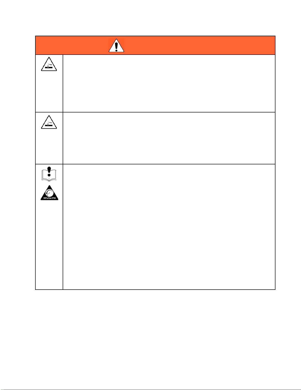
WARNING
PRESSURIZED ALUMINUM HAZARD
Use of fluids that are incompatible with aluminum in pressurized equipment can cause serious
chemical reaction and equipment rupture. Failure to follow this warning can result in death,
serious injury, or property damage.
• Do not use 1,1
solvents or fl
• Many other fluids may contain chemicals that can react with aluminum. Contact your material
supplier for compatibility.
PLASTIC PARTS CLEANING SOLVENT HAZARD
Many solvents can degrade plastic parts and cause them to fail, which could cause serious
injury or property damage.
• Use only co
parts.
•SeeTechnical Data in this and all other equipment instruction manuals. Read fluid and
solvent manufacturer’s MSDSs and recommendations.
EQUIPMENT MISUSE HAZARD
Misuse can cause death or serious injury.
• Do not op
• Do not exceed the maximum working pressure or temperature rating of the lowest rated
system component. See Technical Data in all equipment manuals.
• Use fluids and solvents that are compatible with equipment wetted parts. See Technical Data
in all equipment manuals. Read fluid and solvent manufacturer’s warnings. For complete
information about your material, request MSDS from distributor or retailer.
•Donot
equip
• Check equipment daily. Repair or replace worn or damaged parts immediately with genuine
manufacturer’s replacement parts only.
• Do not alter or modify equipment.
•Usee
• Route hoses and cables away from traffic areas, sharp edges, moving parts, and hot surfaces.
• Do not kink or over bend hoses or use hoses to pull equipment.
•Keep
• Comply with all applicable safety regulations.
leave the work area while equipment is energized or under pressure. Turn offall
ment and follow the Pressure Relief Procedure when equipment is not in use.
quipment only for its intended purpose. Call your distributor for information.
children and animals away from work area.
,1-trichloroethane, methylene chloride, other halogenated hydrocarbon
uids containing such solvents.
mpatible water-based solvents to clean plastic structural or pressure-containing
erate the unit when fatigued or under the influence of drugs or alcohol.
3A1705J 5
Page 6
Warnings
WARNING
BATTERY HAZARD
The battery may leak, explode, cause burns, or cause an explosion if mishandled.
• Only use the battery type specified for use with the equipment. See Technical Data.
• Battery maintenance must only be performed or supervised by personnel knowledgeable of
batteries and the required precautions. Keep unauthorized personnel awayfrombattery.
• When replaci
minimum, spe
• Do not dispose of battery in fire. The battery is capable of exploding.
• Follow local ordinances and/or regulations for disposal.
• Do not open o
the skin and
• Remove watches, rings, or other metal objects.
• Only use tools with insulated handles. Do not lay tools or metal parts on top of battery.
ng the battery, use the same lead-acid automotive battery, with 800 CCA
cified for use with the equipment. See Technical Data.
r mutilate the battery. Released electrolyte has been known to be harmful to
eyes and to be toxic.
MOVING PA
Moving parts can pinch, cut or amputate fingers and other body parts.
• Keep clear of moving parts.
• Do not operate equipment with protective guards or covers removed.
•Pressur
equipme
ENTAGLEMENT HAZARD
ng parts can cause serious injury.
Rotati
• Keep clear of moving parts.
•Donoto
• Do not wear loose clothing, jewelry or long hair while operating equipment.
• Equipment can start without warning. Before checking, moving, or servicing equipment,
follow the Pressure Relief Procedure and disconnect all power sources.
BURN HAZARD
pment surfaces and fluid that’s heated can become very hot during operation.Toavoid
Equi
re burns:
seve
• Do not touch hot fluid or equipment.
RTS HAZARD
ized equipment can start without warning. Before checking, moving, or servicing
nt, follow the Pressure Relief Procedure and disconnect all power sources.
perate equipment with protective guards or covers removed.
6 3A1705J
Page 7
Important Two-C
omponent Material Information
Important Two-Component Material Information
Isocyanate Conditions
Spraying or dispensing materials containing
isocyanates creates potentially harmful mists,
vapors, and atomized particulates.
Read material manufacturer’s warnings and
material MSDS to know specific hazards and
precautions related to isocyanates.
Prevent inhalation of isocyanate mists, vapors,
and atomized particulates by providing sufficient
ventilation in the work area. If sufficient ventilation
is not available, a supplied-air respirator is required
for everyone in the work area.
To prevent contact with isocyanates, appropriate
personal protective equipment, including
chemically impermeable gloves, boots, aprons,
and goggles, is also required for everyone in the
work area.
Moisture Sensitivity of Isocyanates
Cross-contamination can result in cured
material in fluid lines which could cause serious
injury or damage equipment. To prevent
cross-contamination of the equipment’s wetted
parts, never interchange component A (isocyanate)
and component B (resin) parts.
Isocyanates (ISO) are catalysts used in two
component foam and polyurea coatings. ISO will
react with moisture (such as humidity) to form small,
hard, abrasive crystals, which become suspended in
the fluid. Eventually a film will form on the surface
and the ISO will begin to gel, increasing in viscosity. If
used, this partially cured ISO will reduce performance
and the life of all wetted parts.
The amount of film formation and rate of crystallization
varies depending on the blend of ISO, the humidity,
and the temperature.
Material Self-Ignition
Some materials may become self-igniting if applied
too thickly. Read material manufacturer’s warnings
and material MSDS.
Keep Components A and B Separate
Cross-contamination can result in cured
material in fluid lines which could cause serious
injury or damage equipment. To prevent
cross-contamination of the equipment’s wetted
parts, never interchange component A (isocyanate)
and component B (resin) parts.
To prevent exposing ISO to moisture:
• Always use a sealed container with a desiccant
dryer in the vent, or a nitrogen atmosphere. Never
store ISO in an open container.
• Keep the ISO lube pump reservoir (if installed) filled
with appropriate lubricant. The lubricant creates a
barrier between the ISO and the atmosphere.
• Use only moisture-proof hoses compatible with
ISO.
• Never use reclaimed solvents, which may contain
moisture. Always keep solvent containers closed
when not in use.
• Always lubricate threaded parts with ISO pump oil
or grease when reassembling.
3A1705J
7
Page 8

Important Two-C
omponent Material Information
Foam Resins wi
Agents
Some foam blow
above 90°F (3
especially i
preheating i
ing agents will froth at temperatures
3°C) when not under pressure,
f agitated. To reduce frothing, minimize
n a circulation system.
th 245 fa Blowing
Changing Mate
Changing the material types used in your equipment
requires special attention to avoid equipment damage
and downtime.
• When changin
multiple tim
• Always clean
•Checkwithy
compatibil
• When changi
or polyure
component
have amine
often have
es to ensure it is thoroughly clean.
ity.
as, disassemble and clean all fluid
s and change hoses. Epoxies often
s on the B (hardener) side. Polyureas
amines on the B (resin) side.
rials
g materials, flush the equipment
the fluid inlet strainers after flushing.
our material manufacturer for chemical
ng between epoxies and urethanes
8 3A1705J
Page 9

Proportioner Models
E-30i Series
Proportioner Mo
dels
Auxiliary
Current at
240 V, 60
Hz*
259079
259080
259089
259090
50 Amps 240 V (1)
32 Amps
30 Amps
12 Amps
E-XP2i Series
Auxiliary
Current at
240 V, 60
Hz*
259081
259091
32 Amps
12 Amps
Includes:Part Available
Booster
Heat
(4000
Watts)
Includes:Part Available
Booster
Heat
(4000
Watts)
Air
Compressor
(5000 Watts)
Air
Compressor
(5000 Watts)
Voltage
(phase)
240 V (1)
240 V (1)
240 V (1)
Voltage
(phase)
240 V (1)
240 V (1)
Total
System
Load †
(Watts)
7,700
11,700
7,700
16,700
Total
System
Load †
(Watts)
11,700
16,700
Max Flow
Rate lb/min
(kg/min)
30 (13.5)
30 (13.5)
30 (13.5)
30 (13.5)
Max Flow
Rate gpm
(lpm)
2.0 (7.6)
2.0 (7.6)
Approximate Output per Cycle (A+B)
gal. (liter)
0.0272
(0.1034)
0.0272
(0.1034)
0.0272
(0.1034)
0.0272
(0.1034)
Approximate Output
per Cycle
(A+B) gal.
(liter)
0.0203
(0.0771)
0.0203
(0.0771)
Maximum
Fluid
Working
Pressure
psi (MPa,
bar)
2000 (13.8,
138)
2000 (13.8,
138)
2000 (13.8,
138)
2000 (13.8,
138)
Maximum
Fluid
Working
Pressure psi
(MPa, bar)
3500 (24.1,
241)
3500 (24.1,
241)
Total system watts used by system, based on maximum heated hose length of 310ft(94.5m)for
each unit.
* Full load amps available for auxiliary equipment when all bare-system components are operating
at maximum capabilities. Available auxiliary current is based on 310 ft (94.5 m) of heated hose.
An additional 3.0 amps of auxiliary current is available for each 50 ft (15.2 m) section of heated
hose that is not used.
lable auxiliary current will be less when the engine is de-rated for site altitude. Reduce the
Avai
lable Auxiliary Current in the chart by 2.5 Amps per 1000 ft (300 m) elevation increments. If the
Avai
lable auxiliary current is less than zero, the system configuration may not support the full load
avai
at altitude.
at th
Includes Complete Air Compressor Kit 24K335.
Refer to Circuit Breaker Configuration Options, page 29.
e Approvals, page 10.
Se
3A1705J 9
Page 10
Systems
Approvals
Model Approvals:
259079
Conforms to ANSI/UL Std. 73 Certified to CAN/CSA Std. C22.2 No. 68
259080
259081
Conforms to ANSI/UL Std. 499 Certified to CAN/CSA Std. C22.2 No. 88
Systems
Maximum
Part
AP9079
AP9080
AP9081
AP917
AP918
AP91
CS9079 2000 (13.8, 138)
CS9080 2000 (13.8, 138)
CS9081 3500 (24.1, 241)
CS9179 2000 (13.8, 138)
CS9180 2000 (13.8, 138)
CS9181 3500 (24.1, 241)
P29079
P29080
P29081
P29179
P29180
P29181
Fluid Working
Pressure psi
(MPa, bar)
2000 (13.8, 138)
2000 (13.8, 138)
3500 (24.1, 241)
9
2000 (13.8, 138)
0
2000 (13.8, 138)
81
3500 (24.1, 241)
2000 (13.8, 138)
2000 (13.8, 138)
3500 (24.1, 241)
2000 (13.8, 138)
2000 (13.8, 138)
3500 (24.1, 241)
Remote
Proportioner
259079 24K240 246050 Fusion™
259080 24K240 246050 Fusion
259081 24K241 246055 Fusion
9
25907
0
25908
81
2590
79
2590
080
259
081
259
9079
25
59080
2
59081
2
259079 24K240 246050
259080 24K240 246050
259081 24K241 246055
259079 ✓ 24K394 246050
259080 ✓ 24K394 246050
259081 ✓ 24K395 246055
Display
Module Kit
✓ 24K39
✓ 24K39
✓24K3952460
✓24
✓2
✓2
Heated Hose
50 ft (15
24K2
24K
24K
4K394
4K395
m)
4
4
40
240
241
K394
10 ft (3 m
0
24605
0
24605
55
50
2460
050
246
055
246
6050
24
46050
2
46055
2
Gun
) Model Part
™AP
™AP
n™ AP
Fusio
n™ AP
Fusio
on™ AP
Fusi
Fusion™ CS CS0101
Fusion™ CS CS0101
Fusion™ CS CS0000
Fusion™ CS CS0101
Fusion™ CS CS0101
Fusion™ CS CS0000
Probler® P2 GCP2R1
Probler® P2 GCP2R1
Probler® P2 GCP2R0
Probler® P2 GCP2R1
Probler® P2 GCP2R1
Probler® P2 GCP2R0
AP
246101
246101
246100
24610
24610
00
2461
1
1
10 3A1705J
Page 11
Accessories
Systems with A
Maximum
Part
AP9089
AP9090
AP9091
AP9189
AP9190
AP9191
CS9089 2000 (13
CS9090 2000 (13
CS9091 3500 (2
CS91892000 (
CS91902000 (
CS91913500
P29089
P29090
P29091
P29189
P29190
P29191
Fluid Working
Pressure psi
(MPa, bar)
2000 (13.8, 1
2000 (13.8,
3500 (24.1,
2000 (13.8
2000 (13.
3500 (24.
.8, 138)
.8, 138)
4.1, 241)
13.8, 138)
13.8, 138)
(24.1, 241)
(13.8, 138)
2000
0(13.8,138)
200
0(24.1,241)
350
00 (13.8, 138)
20
000 (13.8, 138)
2
500 (24.1, 241)
3
ir Compressor
Proportioner
259089 ✓ 24K240 246050 Fusion™ AP 246101
38)
259090 ✓ 24K240 246050 Fusion™ AP 246101
138)
259091 ✓ 24K241 246055 Fusion™ AP 246100
241)
,138)
8, 138)
1, 241)
259089 ✓ ✓ 24K394 246050 Fusion™ AP 246101
259090 ✓ ✓ 24K394 246050 Fusion™ AP 246101
259091 ✓ ✓ 24K395 246055 Fusion™ AP 246100
259089 ✓ 24K240 246050
259090 ✓ 24K240 246050
259091 ✓ 24K241 246055
259089 ✓ ✓ 24K394 246050
259090 ✓ ✓ 24K394 246050
259091 ✓ ✓ 24K395 246055
259089 ✓ 24K240 246050
259090 ✓ 24K240 246050
259091 ✓ 24K241 246055
259089 ✓ ✓ 24K394 246050
259090 ✓ ✓ 24K394 246050
259091 ✓ ✓ 24K395 246055
Air
Compressor
Remote
Display
Module Kit
Heated Hose
50 ft
(15 m)
10 ft
(3 m)
Gun
Model Part
Fusion™
Fusion™
Fusion
Fusio
Fusio
Fusi
Prob
Pro
Pro
obler® P2
Pr
robler® P2GCP2R1
P
robler® P2GCP2R0
P
CS
CS
™CS
n™ CS
n™ CS
on™ CS
ler® P2
bler® P2
bler® P2
CS0101
CS0101
CS0000
CS010
CS010
CS00
GCP2
GCP
GCP
P2R1
GC
1
1
00
R1
2R1
2R0
Accessories
Kit Number Description
24N449
24K207
24K338 Remote Display Module Kit
24K335
125970
24M490
24M125
24M178
24M258
24K336 Hose Rack
50 ft (15 m) CAN cable (for remote
display module)
Fluid Temperature Sensor (FTS)
with RTD
Complete Air Compressor Kit
Air Compressor (without air supply
tank)
Air Compressor (mounted 30 gallon
tank)
Air Tank (12 gallons, 113.5 liters)
Air Dryer (desiccant)
Compressor Rack (frame only)
Kit Number Description
15V551
15M483 Remote Display Module Protective
24K334
24K333
24K337 Light Tower Kit
24M174
24L911
121006
24N365
ADM Protective Covers (10 pack)
Covers (10 pack)
Feed Pump Shutdown Kit
Fuel Line and Cable Extension Kit
Drum Level Sticks
Pallet Support Kit
150 ft (45 m) cable (for remote
display module)
RTD Test Cables (to aide resistance
measurements)
3A1705J
11
Page 12
Supplied Manual
s
Supplied Manuals
The following
Refer to these
information.
Manuals are also available at www.graco.com.
Manual Description
3A1705 Reactor E-30i and E-XP2i,
16K761
16K913 Reactor E-
SEBU8311–02Perkins® Engine, Repair-Parts
–
F3231, ver
16
manuals are shipped with the Reactor.
manuals for detailed equipment
Operation
Reactor E-30i and E-XP2i, Startup
Instructions
30i and E-XP2i,
Shutdown I
nstructions
Access at www.perkins.com. Go
to Service and Support/manuals.
Select engine family and type code
“GN”.
Contact Perkins for engine warranty
and service.
Mecc Alte Self-Regulating Alternator
Series NPE, Repair-Parts
Access at www.meccalte.com.
Select “meccalte” logo / Download
/ Instruction Manuals. Select NPE
instruction manual on page 5. Go to
Support and enter serial number for
Parts List and Help Videos.
Contact Mecc Alte for warranty and
service.
pion Air Compressor,
Cham
ation/Maintenance & Parts list.
Oper
arranty and service call
For w
dner-Denver Customer Serivce
Gar
6) 276–3440 or Champion (815)
(86
–3321.
875
Related Manuals
The following manuals are for accessories used with
the Reactor.
Manuals are av
Component manuals in English:
System Manuals
3A1706 Reactor E-30i and E-XP2i,
Displacement Pump Manual
309577 Electric Reactor Displacement Pump,
Feed System Manuals
309572 Heated Hose, Instructions-Parts
309852
309815 Feed Pump
309827
Spray G
309550
312666
313213
Accessory Manuals
3A1902
3A1903 Hose Rack, Instructions-Parts
3A1904 Fuel Tank/Battery Move Kit,
05
3A19
3A1906 Light Tower Kit, Instructions-Parts
3A1907 Remote Display Module,
3A2574
ailable at www.graco.com
Repair-Parts
Repair-Parts
Circulation and Return Tube Kit,
Instructions-Parts
Kits, Instructions-Parts
Feed Pump Air Supply Kit,
Instructions-Parts
un Manuals
Fusion
Fusion
Proble
Compr
Instructions-Parts
Feed Pump Shutdown Kit,
Instructions-Parts
Instructions-Parts
Pallet Support Kit, Instructions-Parts
™APGun
™CSGun
rP2Gun
essor Rack, Instructions-Parts
2
1
3A1705J
Page 13
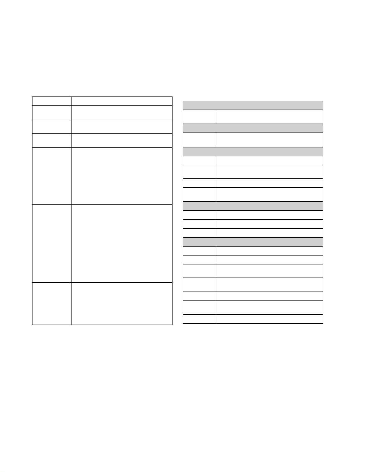
Typical Installation, with circulation
K
M
H
G
J
R
M
K
G
Typical Install
L
ation, with circulation
R
J
A
D
E
S
P
C*
Figure 1
* Shown exposed for clarity. Wrap with tape during operation.
A Reactor Proportioner
BHeatedHose
CFlui
D Heated Whip Hose
E
F
GFee
H
d Temperature Sensor (FTS)
ion Spray Gun
Fus
Air Supply Hose
Gun
d Pump Air Supply Lines
tator Air Supply Line
Agi
J
K Feed Pumps
L Agitator
M Desiccant Dryer
P
R Recirculation Lines
SRe
F
d Supply Lines
Flui
Fluid Manifold (part of gun)
Gun
mote Display Module (optional)
B
3A1705J 13
Page 14
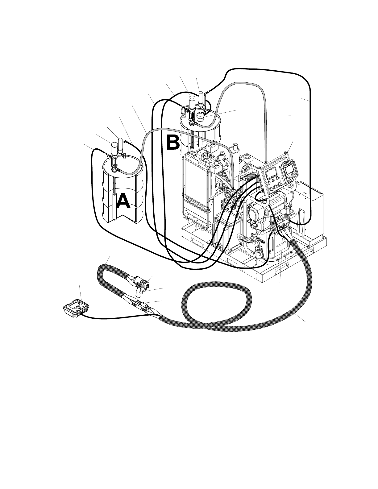
Typical Install
ation, without circulation
Typical Installation, without circulation
K
H
G
J
L
J
M
K
A
G
F
N
D
E
N
S
P
C*
Figure 2
* Shown exposed for clarity. Wrap with tape during operation.
A Reactor Proportioner
B Heated Hose
CFlui
D HeatedWhipHose
E
F
GFee
H
d Temperature Sensor (FTS)
ion Spray Gun
Fus
Air Supply Hose
Gun
d Pump Air Supply Lines
tator Air Supply Line
Agi
J
K Feed Pumps
L Agitator
M Desiccant Dryer
N Bleed Lines
P
SRe
B
d Supply Lines
Flui
Fluid Manifold (part of gun)
Gun
mote Display Module Kit (optional)
4
1
3A1705J
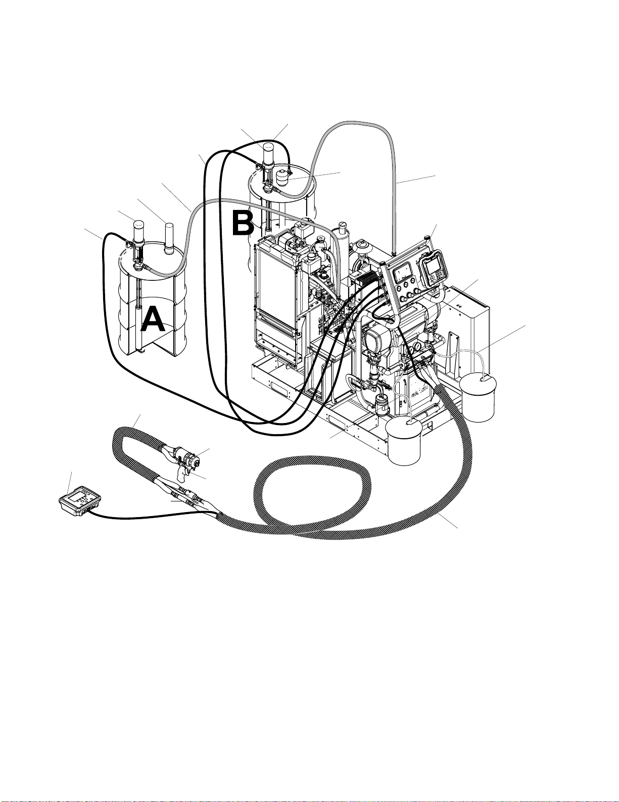
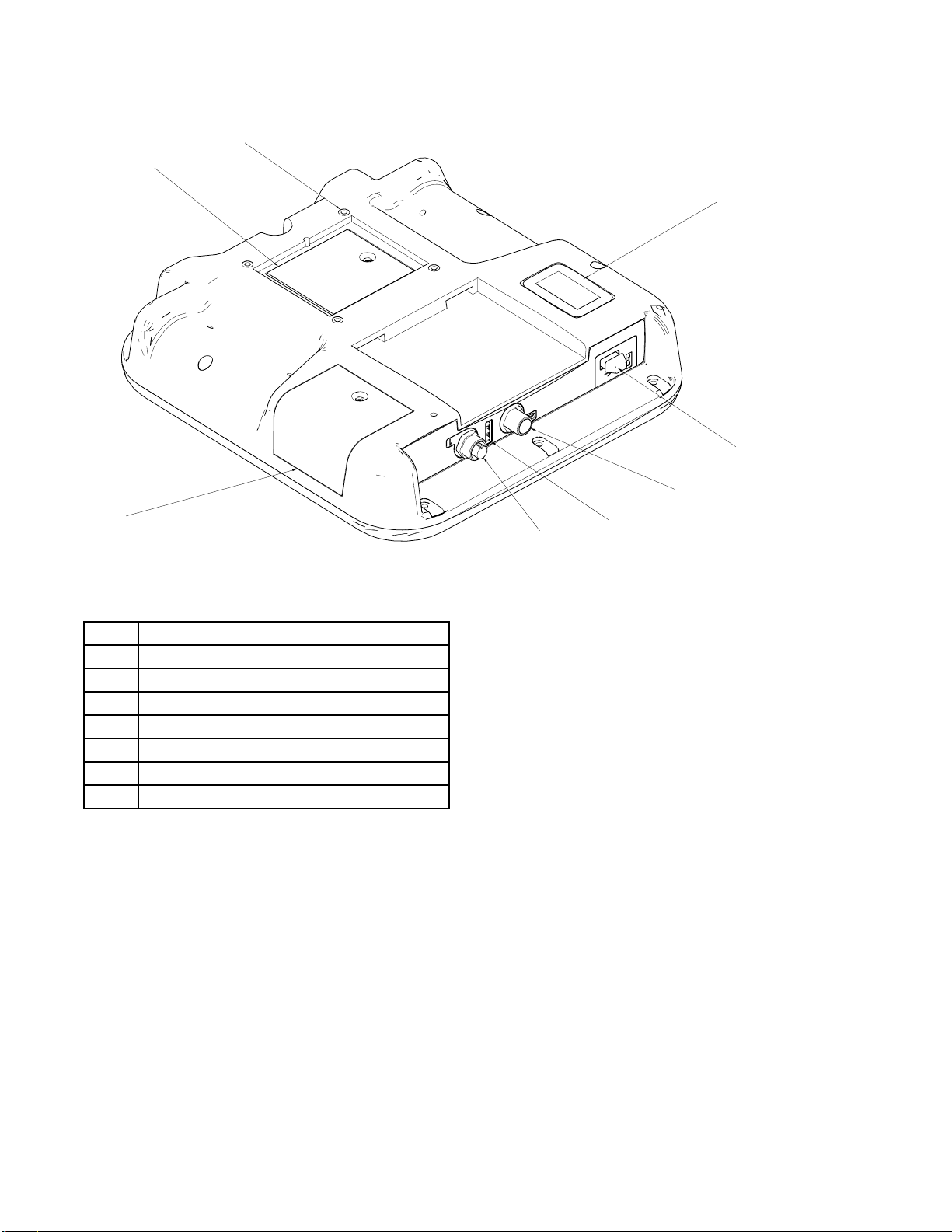
Page 15
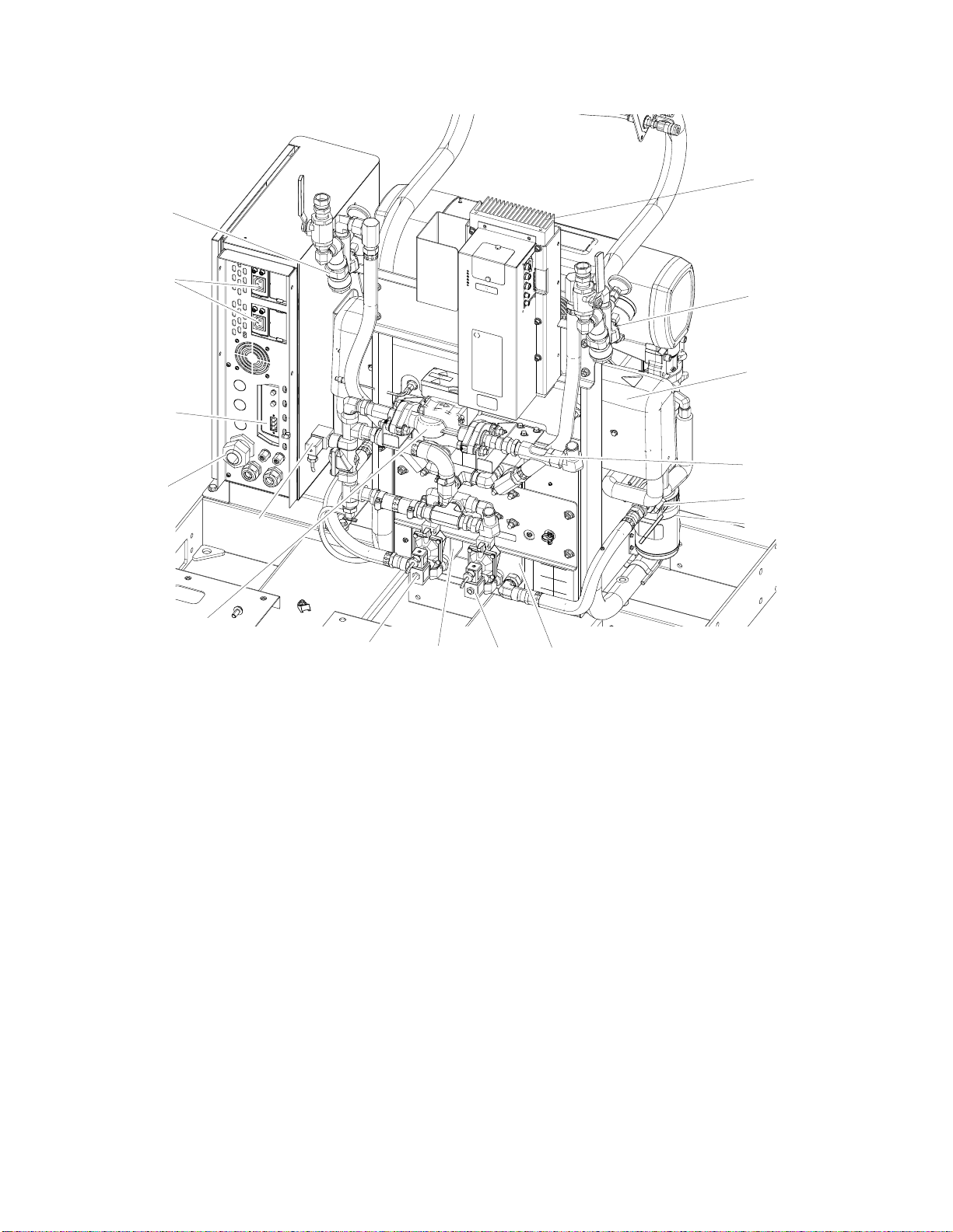
Component Ident
ification
Component Ide
GB SB
GA
SA
FA
HA
BA
ntification
FB
BB
HB
HC
SC
(FM)
PA
PB
PC
GG
DG
EM
Front V
Figure
iew
3
BA
BB
DG Drive
DB Electrical Enclosure
EM Electric Motor
FA
FB
FM
GA Com
GB Com
GG Gen
HA
HB
Compon
Compo
Comp
Comp
Reac
Com
Co
ent A Pressure Relief Outlet
nent B Pressure Relief Outlet
Gear Housing
onent A Fluid Manifold Inlet
onent B Fluid Manifold Inlet
tor Fluid Manifold
ponent A Pressure Gauge
ponent B Pressure Gauge
erator, page 17
ponent A Hose Connection
mponent B Hose Connection
PT
DB
HC Heated Hose Electrical Connectors
MP
PA
PB
PC Prop
PT Pallet
SA Com
SB Com
SC Fl
TA
T
Main Power Switch
Component A Pump
Component B Pump (behind Electrical
Enclosure)
ortioner Control Panel, page 18
ponent A PRESSURE
IEF/SPRAY Valve
REL
ponent B PRESSURE
IEF/SPRAY Valve
REL
uid Temperature Sensor (FTS) Cable
mponent A Pressure Transducer
Co
ehind gauge GA)
(b
B
Component B Pressure Transducer
(behind gauge GB)
MP
3A1705J 15
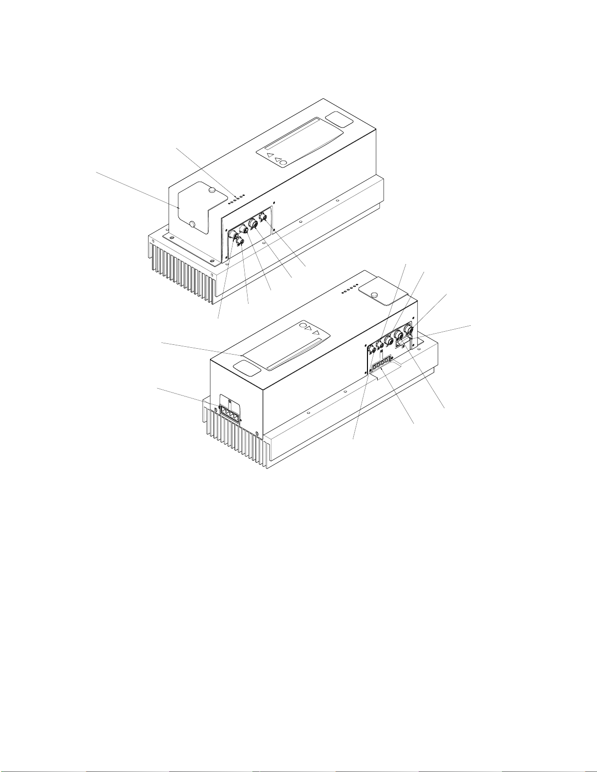
Page 16
Component Ident
FF
ification
MM
LM
HM
EC
Back Vi
Figure
ew
4
CP Circul
EC Elect
FF
Y-str
tempe
FH
Booster Fluid Heater (not included with all
models)
FV
HE
Fluid Inlet Valve (A side shown)
Heat Exchangers (heat exchanger coolant
loop)
HM
Hi
(H
VC
CP
VB
ation Pump
ricalCordStrainRelief
ainer (includes pressure gauge and
rature gauge)
gh Power Temperature Control Module
PTCM) Cable Connections, page 26
HE
HEVA
LM
Low Power Module (LPTCM) Cable
Connections, page 26 (not included with
all models)
LR
MM
ISO Pu
Moto
SG Sigh
VA
VB
Comp
Comp
VC Byp
FF
FH
SG
FV
LR
mp Lubricant Reservoir
r Control Module (MCM), page 23
tGlass
onent A Control Valve
onent B Control Valve
ass Control Valve
16 3A1705J
Page 17
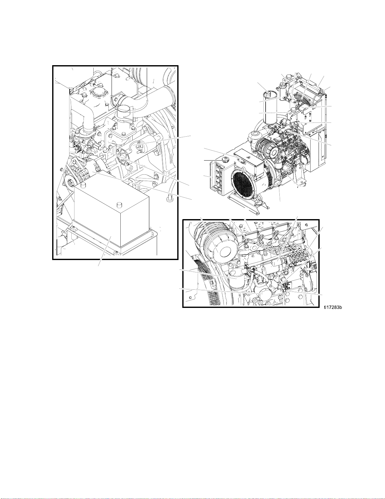
Generator
EX
Component Ident
FH
HB
RF
ification
ER
RC
BE
DF
ST
GD
FS
FT
WS
EA
AF
FJ
GL
HF
EB
OD
HE
TR
OL
EE
FD
FP
ED
Figure 5
AF Air Filter
BE
ery (not supplied)
Batt
DF Diesel Fuel Filter
EA
EB
harge Alternator
12V C
ne Coolant Expansion Bottle
Engi
EE Engine
ED
ine Oil Dipstick
Eng
ER Radiator
EX Exhaust
FD
l Shutoff Solenoid
Fue
FH Filter Housing
FJ Fuel Injector
FP Fuel Pump
FS Di
esel Fuel Fill Cap
OF
FT Diesel Fuel Tank
GD Generator Power Distribution Box
GL Glow Plugs
HB
Heat Exchanger Coolant Expansion Bottle
HE Heat Exchanger
HF
Heat Exchanger Coolant Fill Bottle
OD Oil Drain
OF Oil Filter
OL Oil Fill
OS Oil Pressure Switch
RC Engine Coolant Radiator Cap
RF Radiator Fan
ST Starter
TR
Coolant Temperature Sensor
WS Over-Temperature Switch
OS
3A1705J
17
Page 18
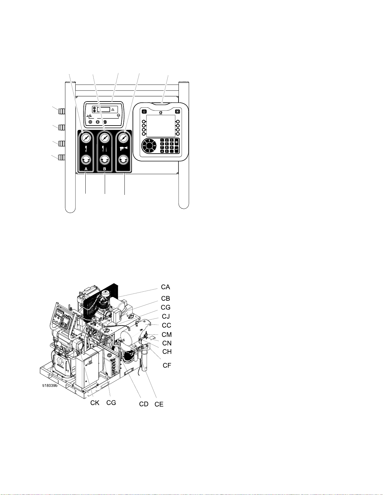
Component Ident
ification
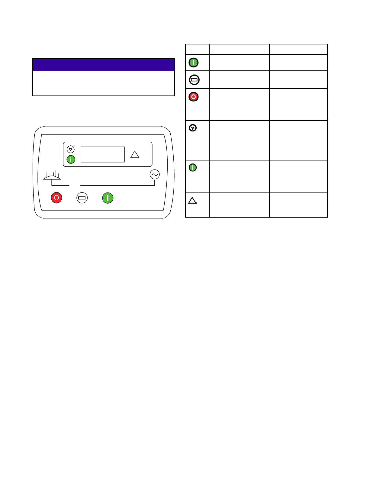
Proportioner
PN
PF*
PG*
PH*
PJ*
Figure 6
Control Panel
PL
PE
PM
PP
PK
PR
PD
ti17151a
PD
PE
PF* Component A Feed Pump Air Outlet
PG* Component B Feed Pump Air Outlet
PH* Agitator Air Outlet
PJ* Gun Air Outlet
PK
PL
PM
PN
PP
PR
*Notforb
Advanced Display Module (ADM), page 19
Engine Control Module, page 24
Component A Feed Pump Air Regulator
Component B Feed Pump and Agitator Air
Regulator
Gun Air Reg
Componen
Componen
Pressure
Gun Pressure Gauge
ulator
t A Feed Pump Pressure Gauge
t B Feed Pump and Agitator
Gauge
reathing air use.
Air Compressor
Select
To ord
Figure 7
models are supplied with an air compressor.
er as an accessory, see Accessories, page 11.
CA Air Com
CB
CC 12 Gal
CD Air Ou
CE
CF Desi
CG Powe
CH
CJ Air T
CK Mai
CL
CM
CN
Power Box
tlet
Desiccant Dryer Assembly
ccant Dryer Air Outlet
rCable
Water Auto Drain Valve
ank Pressure Gauge
n Shutoff Valve
Dryer Inlet Valve
WaterAutoDrainAirValve
Water Manual Drain Valve
pressor
lon Tank
18 3A1705J
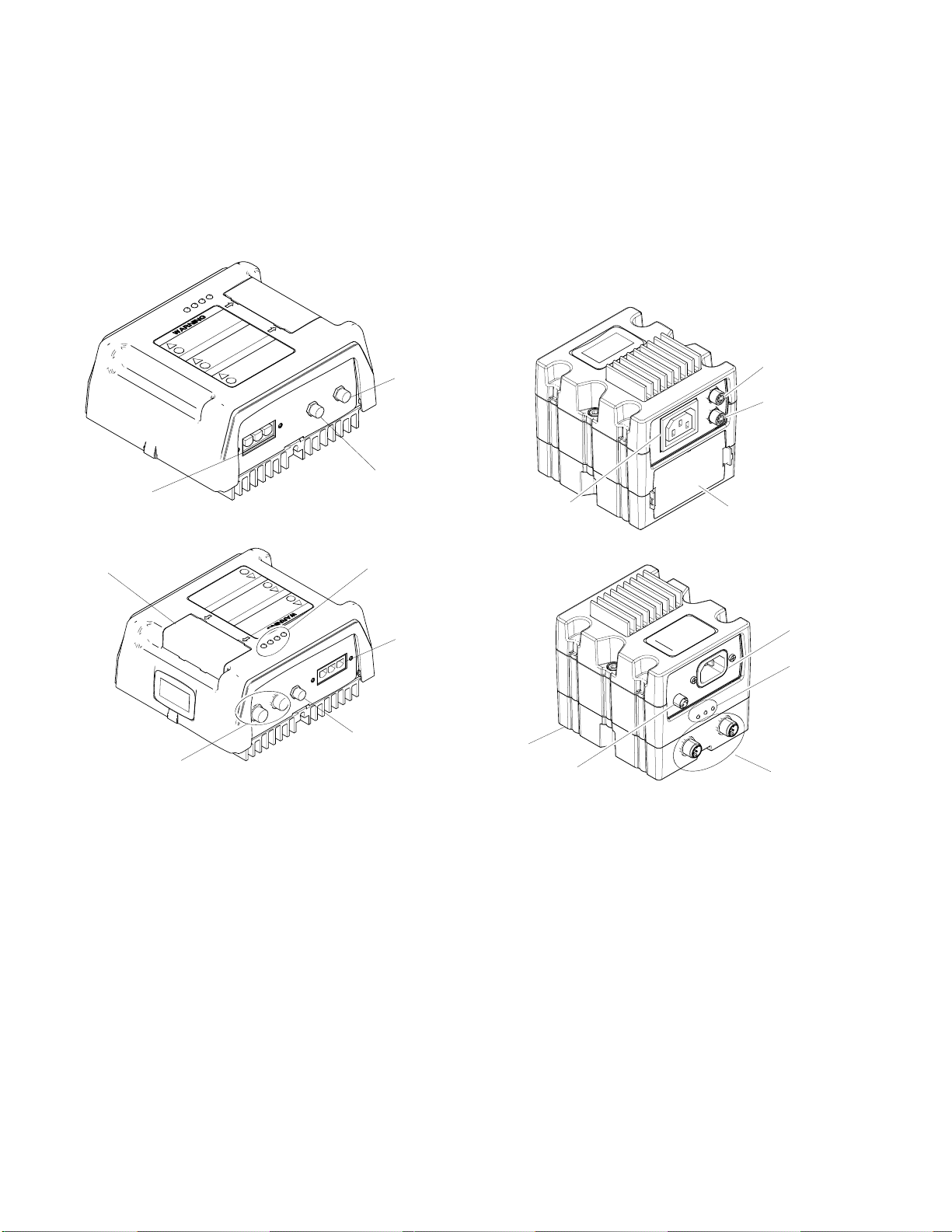
Page 19
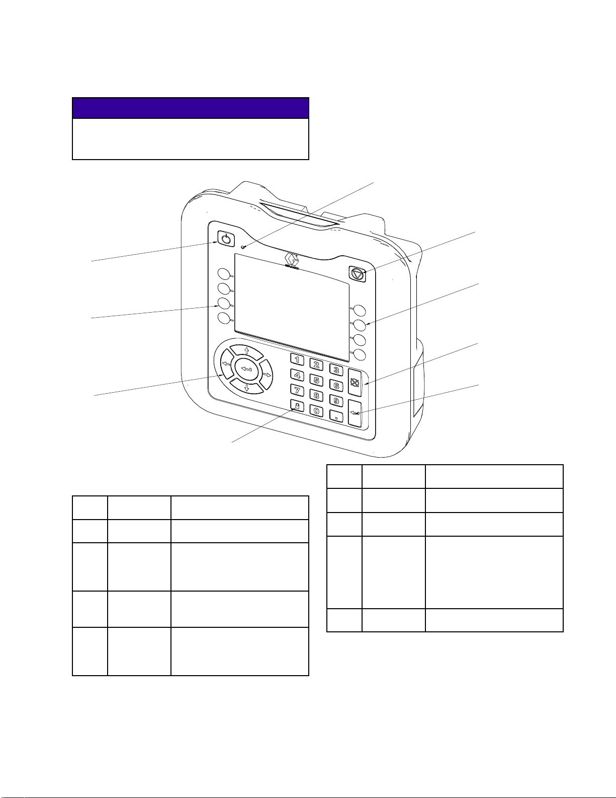
Component Ident
ification
Advanced Disp
lay Module (ADM)
NOTICE
To prevent damage to the softkey buttons, do not
press buttons with sharp objects such as pens,
plastic cards, or fingernails.
A
D
B
C
D
E
H
G
Component Identification — Front
Figure 8
Call
out
A Power
B
C Stop Stops all system processes.
D
Button Function
Powers system on and off.
ff
On/O
System
Status
Indicator
Light
Soft Keys Selects the specific screen
Displays system status.
Is not a safety or emergency
stop.
or operation shown on the
display directly next to each
key.
F
Call
out
E
F Enter Acknowledges a value
GLoc
HNa
Button Functi
l
Cance
k/Setup
vigation
on
ls a selection or
Cance
numbe
change or makes a selection.
Toggles between run and
setup screens. If setup
screens are password
protected, button toggles
between run and password
entry screens.
Na
to
r entry in progress.
vigates within a screen or
a new screen.
3A1705J 19
Page 20
Component Ident
CJ
CS
CR
ification
CK
CL
CM
CN
CP
Compone
Figure 9
CJ Flat Panel Mount (VESA 100)
CK Model and Serial Number
CL USB Port and Status LEDs
CM CAN Cable Connection
CN Module Status LEDs
CP Accessory Cable Connection
CR Token Access Cover
CS Battery Access Cover
nt Identification — Back
System Status Indicator (B)
Cond
Green Solid — Run Mode, System On
Gre
Yellow Solid - Run Mode, System Off
Yellow Flashing - Setup Mode, System Off
itions
en Flashing - Setup Mode, System On
USB Modu
le Status LEDs (CL)
Conditions
Green F
Yellow Solid - Downloading information to USB
Green and Yellow Flashing -ADMisbusy,USB
cannot transfer information when in this mode
Modul
Green Solid - Power applied to module
Yell
Red Steady Flashing - Software upload from token
in progress
Red Random Flashing or Solid -Moduleerrorexists
lashing - Data recording in progress
e Status LEDs (CN) Conditions
ow Solid - Active Communication
20 3A1705J
Page 21
Component Ident
ification
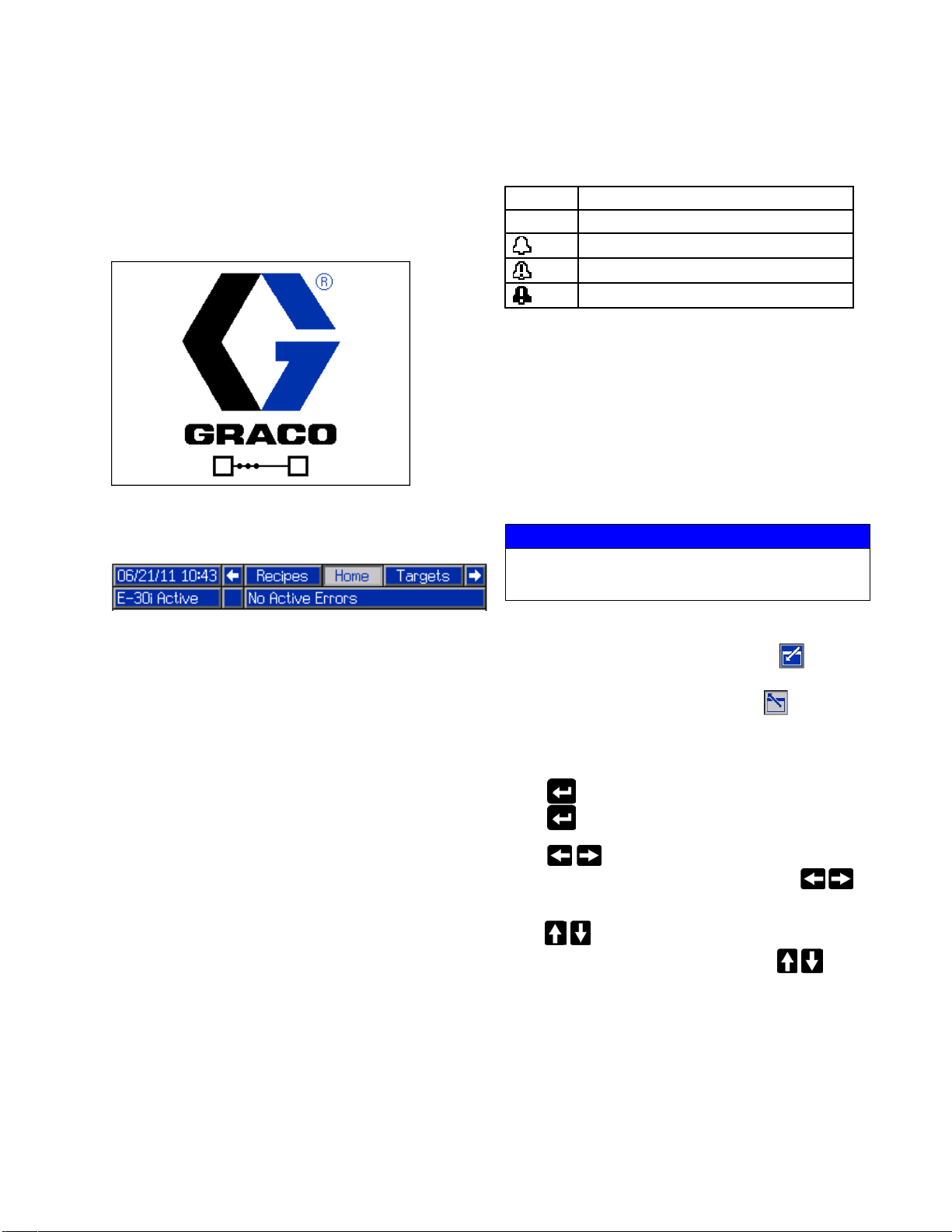
ADM Display Details
Power Up Screen
The following screen appears when the ADM is
powered up. It remains on while the ADM runs through
initialization and establishes communication with other
modules in the system.
Menu Bar
The menu bar appears at the top of each screen. (The
following image is only an example.)
Alarm/Deviation
The current sy
the menu bar. T
stem error is displayed in the middle of
here are four possibilities:
Icon Function
No Icon
No information or no error has occurred
Advisory
Deviation
Alarm
Status
The curren
of the menu
t system status is displayed at the lower right
bar.
Soft Keys
Icons next to the soft keys indicate which mode or
action is associated with each soft key. Soft keys that
do not have an icon next to them are not active in the
current screen.
NOTICE
To prevent damage to the soft key buttons, do not
press buttons with sharp objects such as pens, plastic
cards, or fingernails.
Date and Time
The date and time are always displayed in one of the
following formats. The time is always displayed as a
24-hour clock.
• DD/MM/YY HH:MM
• YY/MM/DD HH:MM
• MM/DD/YY HH:MM
Arrows
The left and right arrows indicate screen navigation.
Screen Menu
The screen menu indicates the currently active screen,
which is highlighted. It also indicates the associated
screens that are available by scrolling left and right.
System Mode
The current system mode is displayed at the lower left
of the menu bar.
Jump In/Jump Out
In screens that have editable fields, press to access
the fields and make changes. When changes are
complete press again to exit edit mode.
Navigation within Screens
Press to open drop-down menus on Setup screens.
Press
Press
navigate left and right within a screen. Press
select digits to change within a field.
Press
up and down within a screen. Also press
move between fields within a drop-down menu, and to
increment or decrement numbers within a field.
to enter changes or make a selection.
to navigate to new screens and to
to navigate to new screens and to navigate
to
to
3A1705J
21
Page 22
Component Ident
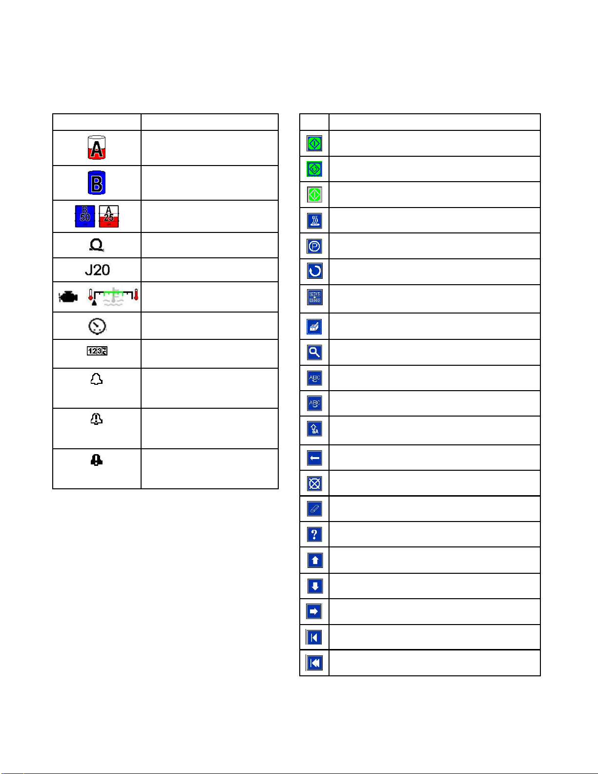
Icons
ification
Icons
Icon Function
Component A
Component B
Estimated Supply Material
Hose Temperature
Jog Mode Speed
Engine Coolant Temperature
Pressure
Cycle Counter (press and
hold)
Advisory.
See Errors, page 51 for more
information.
Softkeys
Icon Function
Start Proportioner
Start and Stop Proportioner in Jog Mode
Stop Proportioner
Turn on specified heat zone.
Park component A pump
Enter Jog Mode. See Jog Mode, page 60
Reset Cycle Counter
(press and hold)
Select Recipe
Search
Move Cursor Left One Character
Move Cursor Right One Character
Deviation.
See Errors, page 51 for more
information
Alarm.
See Errors, page 51 for more
information
Toggle between upper-case, lower-case, and
numbers and special characters.
Backspace
Cancel
Clear
Troubleshoot Selected Error
Increase value
Decrease value
Next screen
Previous screen
urntofirstscreen
Ret
2
2
3A1705J
Page 23
Component Ident
ification
Motor Control
MA
MC
Module (MCM)
MB
1A
10
1B
6
7
3
2
9
11
12
Motor Control Module
Figure 10
MA
MB
MC
1A,
1B
2
3
5
6
Token and Rotary Switch Access Cover
Module Status LEDs see Module Status
LEDs (CN) Conditions, page 20
Warning Label
CAN Communication Connections
Heat Exchanger Control Vave Output (to
load center)
Two-way Splitter to A and B Heat
Exchanger Temperature Sensors
ngine Coolant Temperature Sensor
E
ump Cycle Switch
P
13
5
7
8
9
10
11 Not used
12
13
MCM Rotary Switch Positions
=E-30i
0
1=E-XP2i
onal Accessory Connection: Feed
Opti
Shut Down Kit
Pump
ssure Transducer B (Blue) side
Pre
ssure Transducer A (Red) side
Pre
or Brush Wear and Over-Temperature
Mot
sor Connection
Sen
M Power Input Connection
MC
tor Power Connection
Mo
8
3A1705J 23
Page 24
Component Ident
ification
Engine Contro
l Module
NOTICE
To prevent damage to the softkey buttons, do not
press buttons with sharp objects such as pens,
plastic cards, or fingernails.
For more information about the engine control module,
see Appendix A: Engine Control Module, page 93.
Icon Description Function
On Start Engine
Auto
Off Stop all system
Scroll Scroll through the
Page Sele
Error La
ct
mp
Auto mode (not
used)
processes. Is
not a safety or
emergency stop.
instruments or
recorded events
on the currently
displayed page
Toggle between
the information
page and the error
log page
es error
Indicat
is prese
generat
nt on
or
Figure 1
Engine Control Module
1
4
2
3A1705J
Page 25
Component Ident
ification
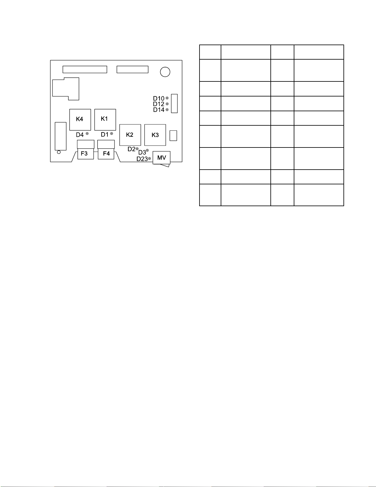
Load Center
F3 Radiator Fan Fuse
F4
K1 Fuel Relay
K2
K3
K4 Radiator Fan Relay
MV
Load Center Power Fuse
Starter Relay
Glow Plug Relay
Manual Valve Switch
LED
D1
D2
D3
D4
D10
D12
D14
D23
Related
Component
Fuel Shutoff
Solenoid (FS)
Starter (ST)
Glow Plugs
(GL)
Radiator F
(RF)
A Coolant Valve
B Coolant Valve
Bypas
Valve
Manual Valve
Switch (MV)
an
s Coolant
Color
Green
Red
Green
Green
Red
Blue
Green
Red
ON-State
Description
Fuel shutoff
solenoid on the
engine is open.
Starter is
cranking.
Glow plugs are
heating.
Radiator fan is
on.
A-side (red)
coolant valve is
open.
B-side
coolan
open.
Bypas
valve
Manu
swit
ON po
(blue)
tvalveis
s coolant
is open.
al valve
ch is in the
sition.
3A1705J 25
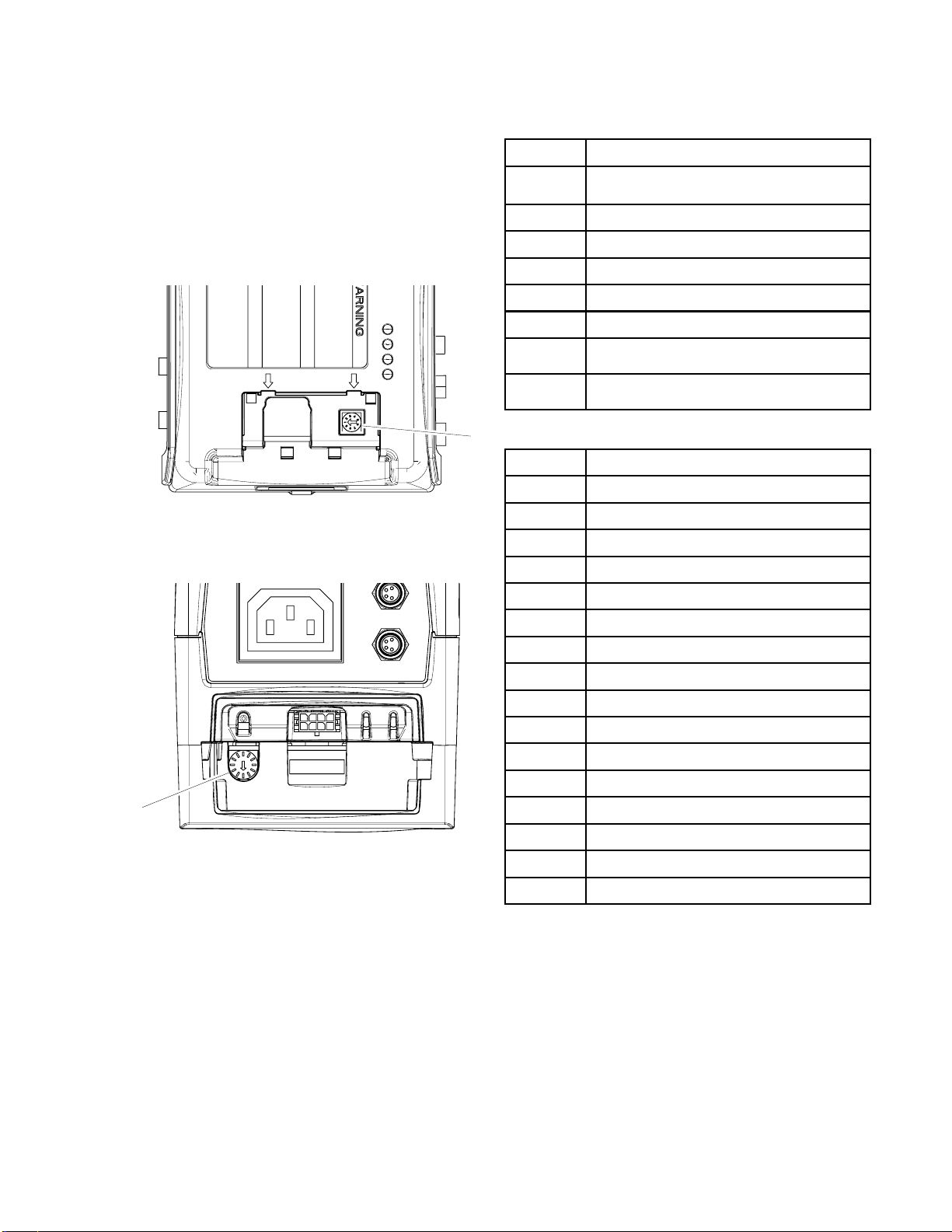
Page 26
Component Ident
ification
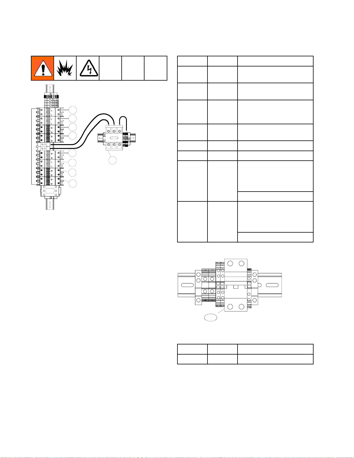
Temperature C
Located inside the Electrical Enclosure (DB).
ontrol Modules
High Power Temperature Control Module (HPTCM) Cable Connections
2
1
3
Figure 12
7
8
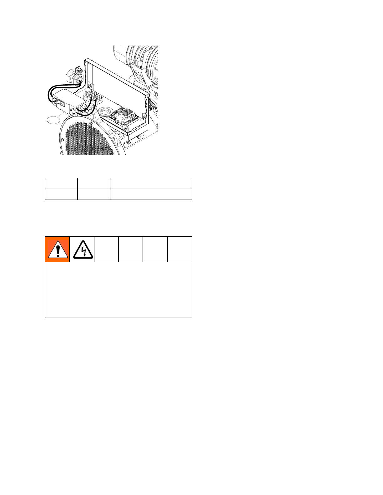
Low Power Module (LPTCM) Cable Connections
Only used with E-XP2i and E-30i models with booster
heat.
1
2
3
Figure 14
7
6
re 13
Figu
1Notu
2
3
4
5
6
7
8
sed
Fluid Temperature Sensor (FTS)
Connection
put Power Connection
Out
tactor Control Connection
Con
ut Power Connection
Inp
N Communications Connections
CA
tary Switch, Token Access
Ro
dule Status LEDs (see
Mo
vanced Display Module (ADM), page 19,
Ad
CN) for conditions
(
5
4
9
4
Figure 15
1
2
3
4 Not used
5
6
7
8
9Base
Over-Temperature Switch Connection
Booster Heat Temperature Sensor
Connection
Output Power Connection
Input Power Connection
CAN Communications Connections
Rotary Switch, Token Access
Module Status LEDs (see
Advanced Display Module (ADM), page 19,
(CN) for conditions
5
8
6
26 3A1705J
Page 27
Component Ident
ification
Adjust Rotary Switch
The rotary switch setting indicates which zone the
temperature control module will control in the system.
The HPTCM uses an 8-position rotary switch. The
LPTCM uses a 16-position rotary switch.
Set the rotar
according to
HPTCM Rotary Switch Location
Figure 16
y switch (S) to the specific selection
the settings listed in the following tables.
HPTCM A and B Rotary Switch Settings
Setting
0HeatedHose
1 Not Used
2 Not Used
3 Not Used
4 Not Used
5
6 Not Used
7
LPTCM A and B Rotary Switch Settings
S
Setting
0 Not Used
1 Not Used
2 Not Used
3 Not Used
Zone
Not Used
Not Used
Zone
S
LPTCM Rotary Switch Location
Figure 17
4 Not Used
5
6 Not Used
7
8 Not Used
9 Not Used
A Booster Heat A
B Booster Heat B
C
D Not Used
E Not Used
F Not Used
Not Used
Not Used
Not Used
3A1705J
27
Page 28
Component Ident
ification
Circuit Break
CB08
CB07
CB06
CB05
CB04
CB03
CB02
CB01
Circuit B
Figure 1
reakers Inside Electrical Enclosure (DB)
8
Note
ers
CT01
Ref. Size Component
CB01
30 A High Power Tem
Control Modu
CB02
20 A
Motor Control Module
(MCM)
CB03
5A
Two Motor Fans, Cabinet
Fan, Power Supply, and
Coolant Circulation Pump
CB04*
30 A
Auxiliary
Power (Air
Compress
CB05*
CB06*
10 A Auxiliary Power
20 A Auxilia
ry Power
E-XP2i and E-30i With
Heat: Low Power
CB07
15 A
Temperature Control
Module (LPTCM) A
E-30i:
Auxiliary
E-XP2i and E-30i With
Heat: Low Power
CB08 15 A
Temperature Control
Module (LPTCM) B
E-30i: Auxiliary
perature
le (HPTCM)
or)
Not all wires are shown.
*SeeCircuit Breaker Configuration Options, page 29.
CB20
Circuit Breakers Inside Proportioner Cabinet
Figure 19
Ref. Size Component
CB20
5
0A
eated Hose
H
28 3A1705J
Page 29
Component Ident
ification
CB04 be substituted to accommodate larger loads
or a sub-panel. The total auxiliary equipment
loads added to the configuration must be limited
to the system’s available auxiliary current. See
Proportioner Models, page 9, for available auxiliary
current at 240V, 60Hz.
CB10
Circuit Breakers Inside Alternator Assembly
Figure 20
Ref. Size Component
CB10
90 A 120/240V Alternator
Circuit Breaker Configuration Options
Improper configurat
All changes from the
configuration must
and Local safety an
a qualified electri
changes. See page 2
breaker configura
The Electrical Enclosure (DB) circuit breaker
configuration described in the tables on the previous
page is the recommended configuration.
Sub-Panel Options
ion can result in electric shock.
recommended circuit breaker
meet all National, State,
d electrical codes. Consult
cian before attempting any
7 and 28 for correct circuit
tion.
See the React
breakers and
used must mee
or repair manual for optional circuit
their current ratings. Circuit breakers
t UL489 specifications.
Auxiliary Wiring Diagram Options.
The generator supplies power in a 3-wire,
single-phase, mid-point neutral wiring configuration.
For 240 VAC loads, wire the load across the output
terminals of the circuit breaker. For 120 VAC loads,
wire the load between the neutral terminal blocks
next to the three pole main power switch (CT01)
to one pole of the circuit breaker. See electrical
diagrams in Reactor repair manual.
Disable L
PTCMs For Booster Heat
Both LPTCMs for booster heat must be disabled to
allow use of power for additional auxiliary power.
1. Follow Shutdown instructions. See
Shutdown, page 63.
2. Refer to Disable Optional Booster Heater Wiring
Diagram in the Reactor repair manual.
To repl
follow
ace or repair a circuit breaker, use the
ing steps:
1. Follow Shutdown instructions. See
Shutdown, page 63.
2. Refer to circuit breaker identification table and
electrical diagrams in Reactor repair manual.
3. Loosen four screws connecting wires and bus
bar to circuit breaker that will be replaced.
Disconnect wires.
Some customer changes are acceptable to
accommodate larger loads from auxiliary equipment
or a sub-panel. It is suggested that circuit breakers
4. Pull locking tab out 1/4 in. (6mm) and pull circuit
breaker away from the din rail. Install new circuit
breaker. Insert wires and tighten down all screws.
3A1705J 29
Page 30
Overview
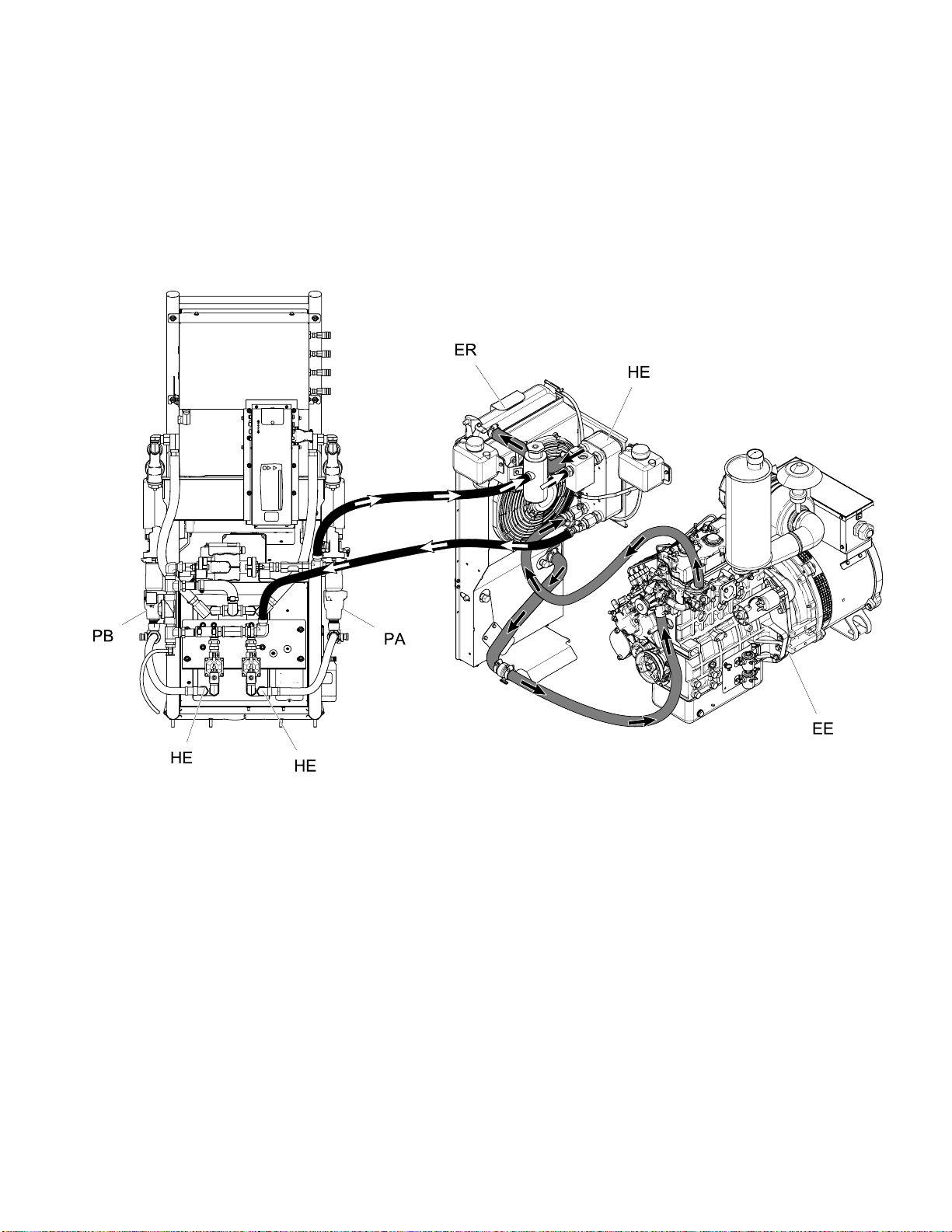
Overview
The system use
released from
component mat
defined on the
The engine coolant loop (gray) circulates heated
coolant from the engine (EE), through the heat
s two coolant loops to use heat
the engine to heat the A and B
erial to the target temperatures
ADM (PD).
exchanger (HE
engine. Coola
(black) captu
inside the he
res heat from the engine coolant loop
at exchanger (HE) near the radiator.
), radiator (ER), and back to the
nt in the proportioner coolant loop
e Coolant Loop and Proportioner Coolant Loop
Engin
re 21
Figu
30 3A1705J
Page 31

Overview
The proportioner coolant loop circulates coolant
through secondary heat exchangers (HE) located
on the back of the proportioner to heat the A
and B component material before the material is
pressurized in the proportioner pumps (PA, PB). After
the A and B material has been heated in the heat
exchangers, the material enters the fluid manifold
(FM) and heated hose.
FM
For models with a booster heater, the A and B
material enters the booster heater after the material
is pressurized in the proportioning pumps to heat the
material higher than 140°F (60°C).
PA
PB
HE
d B Component Material Flow
Aan
ure 22
Fig
3A1705J 31
Page 32

Overview
Coolant only flows through the secondary heat
exchangers when the heat exchanger control valves
(VA, VB) are open and the A and B component
temperatures are below the target temperatures set
on the ADM. See Fig. 24.
When the contr
and B materia
Coolant flows
circulation
coolant fill b
in the engin
ol valves (VA, VB) close, the A
l has reached target temperature.
through the bypass control valve (VC),
pump (CP), sight glass (SG), proportioner
ottle (HF), and back to the heat exchanger
e coolant loop. See Fig. 23
CP
SG
VC
CP
SG
VC
HE
HE
Proportioner Coolant Loop — A and B Valves Open
(heating material)
Figure 24
VB
VA
Propor
(not he
e23
Figur
HE
tioner Coolant Loop — A and B Valves Closed
ating material)
VB
HE
VA
32 3A1705J
Page 33

Setup
Setup
NOTICE
Proper system setup, startup, and shutdown
procedures are critical to electrical equipment
reliability. The following procedures ensure steady
voltage. Failure to follow these procedures will
cause voltage fluctuations that can damage
electrical equipment and void the warranty.
NOTICE
Do not remove or separate the proportioner, engine
assembly, or power distribution box from the pallet.
Failure to leave the component mounting intact will
cause heating efficiency degradation, and potential
unsafe wiring and grounding.
Locate Reactor
If system was not ordered with the air compressor,
go to step 2.
1. Forsystemswithanaircompressor, install the
air tank bracket assembly and connect air lines.
For systems without an air compressor, order air
compressor kit 24K335. See manual 3A1902 for
complete installation instructions.
NOTICE
Only use air compressors with a
continuous run head unloader. Repeated
compressor motor startups will cause
errors and shutdown the system. See
Technical Specifications, page 102 for
recommended air compressors and
requirements. Other models may be used, but
motor must not stop and start during operation.
a. Use at least two people to install the air
tank assembly (AT). Secure to frame with
supplied screws (AS) and nuts (AN). See
illustration on next page.
d. Connect air line (A2) between proportioner
air inlet to air dryer outlet.
e. Connect pilot air lines (A3 and A4) between
the air compressor and air tank.
f. Secure water drain lines (A5 and A6) to the
frame and drain outlets.
2. Install hose rack, if ordered. See manual 3A1903
for detailed instructions.
3. Locate Reactor on a level surface that is
nonporous and diesel resistant, such as diamond
plate. See Dimensions, page 96, for clearance
and mounting hole dimensions.
Note
Leave at least 1 ft. (0.3m) distance from
the engine side of the pallet to any wall
for engine maintenance access. See
Fig. 27, page 37.
4. Do not expose Reactor to rain or below 20°F
(-7°C).
NOTICE
To ensure the heat exchanger control valves
open and close properly, do not store Reactor
below 20°F (-7°C).
5. If a wal
propor
the fue
Traile
6. To mou
by ins
frame
side.
l will be installed between the
tioner and generator, remove
l tank and battery bracket. See
r Setup Guidelines, page 35 for instructions.
nt in a trailer, use forklift to move Reactor
erting the forks through the Reactor pallet
. It is recommended to lift from the engine
Bolt pallet directly to trailer frame.
Note
Use Pallet Support Kit 24L911 (rollers not
included) to relocate pallet to mounting
location when forks are unavailable. See
kit manual for instructions.
NOTICE
b. Remove u-bolt holding desiccant container
and add all desiccant pellets (shipped
separately). Replace u-bolt securely. See
manual 309921.
c. Connect air line (A1) between compressor
and air tank inlet.
p the vent holes in the bottom of the
Kee
portioner cabinet open. Make sure there is
pro
obstructed incoming air for the cooling fan at the
un
p of the proportioner cabinet that blows air up into
to
e electric motor. Failure to provide unobstructed
th
coming air can cause the motor to overheat.
in
3A1705J 33
Page 34

Setup
A2
A4
A1
A3
A3
AT
A4
AN
AS
A2
A6
A5
34 3A1705J
Page 35

Setup
Trailer Setup
Route exhaust system away from combustible
materials to prevent materials from igniting or gas
recirculation into a wall, ceiling, or a concealed
space. Provide exhaust system guards to prevent
burns.
Guidelines
NOTICE
Provide recommended size louvers. Failure to do
so can damage the engine and void the engine
warranty.
Exhaust pipes that pass through flammable ceilings
must be guarded by vented metal thimbles that
extend at least 9 in. (228.6 mm) below and above
the roof and are at least 6 in. (152.4 mm) in diameter
larger than the exhaust pipe.
Exhaust pipes that pass through flammable walls
must be guarded by either:
2. Provide radiator exhaust for Reactor. Use a 400
2
in.
(258,064 mm2) minimum louver.
3. Provide air duct to connect radiator exhaust to
louver.
2
4. Provide a 400 in.
air intake louver near the generator.
5. Remove red exhaust cap.
6. Provide a minimum 2 in. (50.8 mm) diameter
engine exhaust outlet with flexible pipe element.
Provide rain cap, or equivalent routing, to prevent
moisture from entering the metal exhaust pipe.
( 258,064 mm2) minimum fresh
• Metal ventilated thimble at least 12 in. (305 mm)
larger than the diameter of the exhaust pipe.
• Metal or other approved fireproofing materials
that provides at least 8 in. (203 mm) of insulation
between the exhaust pipe and flammable material.
Exhaust pipes not covered above must have at least
9 in. (228.6 mm) of clearance from the outside of the
exhaust pipe to adjacent flammable materials.
1. Provide sufficient lighting to safely operate and
maintain system equipment.
Radiator Exhaust and Air Intake Louvers
Figure 25
3A1705J 35
Page 36

Setup
Install Wall (
Install a wall between the proportioner and generator
to:
• Temperature condition the trailer space where
chemical is stored. Check with chemical
manufacturer for chemical storage temperatures.
• Reduce noise for the operator while the Reactor
is running.
The supplied fuel lines and battery cable may need
to be replaced if a wall is installed between the
proportioner and generator. Purchase the Fuel Line
and Battery Cable Extension Kit 24K333.
1. If necessar
Drain Cool
need to be d
Note
Battery must be connected to starter to
drain coolant from system.
2. Remove screws and battery bracket from the
pallet.
optional)
y drain coolant from system. See
ant, page 69. Coolant lines do not
isconnected to install a wall.
3. Remove fuel tank from the pallet.
a. Remove the mou
spacers.
b. Disconnect in
fuel tank.
c. Use two peopl
and place whe
accessible.
Note
Do not mount fuel tank in front of
the generator air intake or where it
will limit opening and access to the
electrical enclosure (DB).
4. Install wall (IW) where the fuel tank was located.
Ensure there is at least 1.25 in. (31.75 mm)
between the wall, exhaust muffler, and MCM.
See Fig. 27, page 37.
Note
To prevent an air pocket from forming
inside the coolant lines between the
proportioner and generator, ensure
there is a constant rise in elevation if
the coolant lines are adjusted. Failure
tohaveaconstantriseinelevation
will reduce heating efficiency. See
Fig. 28, page 37.
nting screws, supports, and
let and outlet fuel lines from the
e to lift fuel tank off of the pallet
re the fuel fill spout is easily
ve Battery Bracket and Fuel Tank
Remo
re 26
Figu
5. Reconnect inlet and outlet fuel lines.
6. Install spacers, supports, and screws through
the fuel tank and tighten to the floor. Torque to
40 ft-lbs (54 N•m).
7. Place battery bracket over fuel tank or near the
Reactor. Remove existing battery cables from
engine and replace with the cables provided from
the fuel line and battery cable extension kit.
8. Install mounting bolts through battery bracket and
tighten to the floor. Torque to 40 ft-lbs (54 N•m).
Note
s under the battery bracket help
Pad
bilize the fuel tank during operation.
sta
36 3A1705J
Page 37

Setup
Top View
Figure 2
With Wall
7
Side View With Wall
Figure 28
3A1705J 37
Page 38

Setup
Connect Batte
Improper battery installation or maintenance
may result in electric shock, chemical burns,
or explosion. Battery maintenance must only
be performed or supervised by personnel
knowledgeable of batteries and the required
precautions. Keep unauthorized personnel away
from batteries.
See Technical Specifications, page 102 for battery
requirements and recommended battery size.
1. Secure battery (not supplied) to bracket with
strap.
ry
PC
3. Cover battery terminals with plastic caps (PC)
attached to supplied battery cables.
4. Verify battery was connected properly by
pressing OFF
(PE) to “wake up” the controller screen. Do not
attempt to start the engine until all Setup steps
are complete. See Repair manual if engine
control module doesn’t light up.
on the engine control module
Add Fuel
1. Remove fuel cap (FS) and fill fuel tank with no
more than 20 gallons (75 liters) of diesel fuel.
Replace cap. See Perkins engine manual for
approved diesel fuels.
2. Squeeze prime bulb (P) to prime engine. Press
the prime bulb repeatedly until fuel begins to
return to the fuel tank.
Figure 29
2. Connect battery cable from the engine starter
(ST) and chassis to the battery. Connect the
black cable to battery negative (-) and the red
cabletobatterypositive(+).
NOTICE
Always connect the red battery cable to battery
positive (+) and the black battery cable to the
battery negative (-). Failure to properly connect
the battery cable to the battery will damage the
fusible link when the engine control module is
turned ON. Do not bypass the fusible link when
damaged. The fusible link prevents damage
to other system components. See the system
repair manual for repair instructions.
FS
P
Figure 31
eral Equipment Guidelines
Gen
Maintain and inspect the generator, air compressor,
and other equipment per the manufacturer
recommendations to avoid an unexpected shutdown.
Unexpected equipment shutdown will cause voltage
fluctuations that can damage electrical equipment.
Figure 30
38 3A1705J
Page 39

Setup
Electrical Co
Connect air compressor, breathing air, and auxiliary
power electrical connections to the specified circuit
breakers. See Circuit Breakers, page 28.
1. Remove one or more knock-outs on side
of electrical enclosure, as required, and
route wires through for air compressor,
breathing air, and auxiliary equipment. See
Circuit Breaker Configuration Options, page 29,
for more information.
nnections
Connect Feed Pumps
1. Install feed pumps (K) in component
A and B supply drums. See
Typical Installation, with circulation, page 13 and
Typical Installation, without circulation, page 14.
2. Seal component A drum and use desiccant dryer
(M) in vent.
3. Install agitator (L) in component B drum, if
necessary.
4. Connect supply hoses from feed pumps to the
component A and component B material inlets
on the system. Ensure A and B inlet valves are
closed.
PF
PG
PJ
PH
Ref Air Outlet
PF A Pump
PG
PH Agitator
PJ
Note
Agitator air supply (PH) includes a small
internal restriction orifice to limit the air
flow to minimize air compressor load.
Maximum supplied air flow is 2.0 scfm
(0.1 m3/min) at 100 psi (0.7 MPa, 7 bar).
Designed for use with Twistork agitator
224854. Do not use the agitator air outlet
(PH) for any other component.
BPump
Gun
Breathing Air
Note
Supply hoses from feed pumps should
be 3/4 in. (199 mm) ID.
5. Connect air lines to proportioner. Ensure
components are properly connected to correct
location.
3A1705J 39
Breathing the air from the compressed air supply
can cause serious injury if inhaled.
y use an independent and approved
•Onl
athing air system with adequate air flow to
bre
vide clean breathable air.
pro
Page 40

Setup
Connect Press
Do not operate Reactor without all covers and
shrouds in place.
1. Recommended: Connect high pressure
hose (R) to relief fittings (BA, BB) of both
PRESSURE RELIEF/SPRAY valves. Route
hose back to component A and B drums. See
Typical Installation, with circulation, page 13.
2. Alternately: Secure supplied bleed tubes (N)
in grounded, sealed waste containers (H). See
Typical Installation, without circulation, page 14.
ure Relief Lines
Install Fluid Temperature Sensor
The Fluid Temperature Sensor (FTS) is supplied.
Install FTS between main hose and whip hose. See
Heated Hose manual for instructions.
coded: red for component A (ISO), blue for
component B (RES). Fittings are sized to prevent
connection errors.
Note
Manifold hose adapters (HA, HB) allow
use of 1/4 in. and 3/8 in. ID fluid hoses.
To use 1/2 in. (13 mm) ID fluid hoses,
remove adapters from fluid manifold and
install as needed to connect whip hose.
FM
HA
A
SC
C
HB
B
V
Connect Heated Hose
See Heated Hose manual for detailed instructions on
connecting heated hoses.
Note
The FTS (C) and whip hose (D) must be used
with heated hose. Hose length, including
whip hose, must be 60 ft (18.3 m) minimum.
NOTICE
Apply grease on all system and hose fluid fittings.
This lubricates the threads and prevents material
from hardening on the threads.
1. Turn main power switch OFF .
2. Assemble heated hose sections, FTS, and whip
hose.
3. Connect A and B hoses to A and B outlets on
Reactor fluid manifold (FM). Hoses are color
Figure 32
4. Connect cables (C). Connect electrical
connectors (V). Be sure cables have slack
when hose bends. Wrap cable and electrical
connections with electrical tape.
5. Connect quick-disconnect pin fitting to 4 ft air
hose, shipped loose. Connect other hose end to
the gun air hose in the heated hose bundle. Push
pin fitting into the lowest air panel outlet (PJ).
Figure 33
40 3A1705J
Page 41

Setup
Close gun fluid
manifold valves A and
B
Connect Whip Hose to Gun Or Gun Fluid Manifold
See hose manual for proper connections.
Pressure Check Hose
See hose manual. Pressure check for leaks. If
no leaks, wrap hose and electrical connections to
protect from damage.
or vehicle chassis or, if stationary, to true earth
ground. Remove bolt and braided cable from
pallet. Install grounding cable terminated with a
ring terminal (cable and terminal not supplied)
under braided cable. Reinstall bolt and torque
to minimum 25 ft-lbs (34 N∙m). An alternate
grounding location is to the ground bar (CB02) in
the electrical enclosure. Follow all National, State,
and Local safety and fire codes.
Connect Remote Display Module
See Remote Display Module kit manual for
installation instructions.
Grounding
The equipment must be grounded to reduce the
risk of static sparking and electric shock. Electric
or static sparking can cause fumes to ignite or
explode. Improper grounding can cause electric
shock. Grounding provides an escape wire for the
electric current.
•
Reactor System:
an appropriately sized conductor to the trailer
System must be grounded with
•
Spray gun:
See Install Fluid Temperature Sensor, page 40.
Do not disconnect ground wire or spray without
whip hose.
•
Fluid supply containers:
Object being sprayed:
•
Solvent pails used when flushing:
•
code. Use only metal pails, which are conductive,
placed on a grounded surface. Do not place pail
on a nonconductive surface, such as paper or
cardboard, which interrupts grounding continuity.
•
To maintain grounding continuity when flushing or
relieving pressure,
firmly to the side of a grounded
trigger gun.
connect whip hose ground wire to FTS.
follow your local code.
follow your local code.
follow your local
hold a metal part of spray gun
metal
pail, then
3A1705J
41
Page 42

Setup
Supply Wet Cup
s With Throat Seal
Liquid (TSL)
Pump rod and connecting rod move during
operation. Moving parts can cause serious injury
such as pinching or amputation. Keep hands and
fingers away from wet-cup during operation.
To prevent the pump from moving, turn the main
power switch OFF.
• Component A (ISO) Pump: Keep reservoir (R) filled
with Graco Throat Seal Liquid (TSL), Part 206995.
Wet-cup piston circulates TSL through wet-cup, to
carry away isocyanate film on displacement rod.
• Component B (Resin) Pump: Check felt washers
in packing nut/wet-cup (S) daily. Keep saturated
with Graco Throat Seal Liquid (TSL), Part No.
206995, to prevent material from hardening on
displacement rod. Replace felt washers when worn
or contaminated with hardened material.
S
Component B Pump
Figure 35
R
Component A Pump
Figure 34
2
4
3A1705J
Page 43

Advanced Displa
yModule(ADM)Operation
Advanced Disp
When main powe
power switch
screen will b
initializat
Then the power key icon screen will display until the
ADM power on/off button (A)
first time after system power-up.
To begin using the ADM, the machine must be active.
To verify the machine is active, verify that the System
Status Indicator Light (B) is illuminated green, see
Advanced Display Module (ADM), page 19.Ifthe
System Status Indicator Light is not green, press
the ADM Power On/Off (A) button
Status Indicator Light will illuminate yellow if the
machine is disabled.
ion is complete.
r is turned on by turning the main
(MP) to the ON position, the splash
e displayed until communication and
lay Module (ADM) Operation
is pressed for the
. The System
Perform the following tasks to fully setup your system.
1. Select pr
Alarm to a
2. Enter, en
Recipes S
3. Set gene
Advance
4. Set unit
Advance
5. Set USB
Advanc
6. Set tar
Target
7. Set co
level
8. Ensur
home s
essure for the Pressure Imbalance
ctivate. See System Screen , page 47.
able, or disable recipes. See
creen, page 47.
ral system settings. See
d Screen 1 — General, page 46.
sofmeasure. See
d Screen 2 — Units, page 46.
settings. See
ed Screen 3— USB, page 46.
get temperatures and pressure. See
s, page 50.
mponent A and component B supply
s. See Maintenance, page 51.
e engine is at operating temperature on the
creen.
3A1705J 43
Page 44

Advanced Displa
yModule(ADM)Operation
Setup Mode
The ADM will start in the Run screens at the Home screen. From the Run screens,press to
access the Setup screens. The system defaults with no password, entered as 0000. Enter the
current password then press .Press to navigate through the Setup Mode screens. See
Setup Screens Navigation Diagram, page 45.
Set Passwor
Set a password to allow Setup screen access, see Advanced Screen 1 – General, page 46. Enter any number
from 0001 to 9999. To remove the password, enter the current password in the Advanced Screen – General
screen and change the password to 0000.
From the Setup screens, press to return to the Run screens.
d
4
4
3A1705J
Page 45

Advanced Displa
yModule(ADM)Operation
Setup Screens Navigation Diagram
Figure 36
3A1705J 45
Page 46

Advanced Displa
yModule(ADM)Operation
Advanced Setu
Advanced setup screens enable users to set units, adjust values, set formats, and view software information
for each component. Press
Advanced setup screen, press
to exit edit mode.
Note
Users must be out of edit mode to scroll
through the Advanced setup screens.
Advanced Screen 1 — General
Use this screen to set the language, date format,
current date, time, setup screens password (0000 –
for none) or (0001 to 9999), screen saver delay, and
enable or disable silent mode.
p Screens
to scroll through the Advanced setup screens, Once in the desired
to access the fields and make changes. When changes are complete press
Advanced Screen 3 — USB
Use this screen to disable USB downloads/uploads,
disable USB log errors, enter the maximum number
of days to download data, and how frequently USB
logs are recorded. See USB Data, page 89.
Advanced Screen 4— Software
Advanced Screen 2 — Units
This screen displays the software part number and
Use this screen to set the temperature units, pressure
units, volume units, and cycle units (pump cycles or
volume).
46 3A1705J
software version for the Advanced Display Module,
Motor Control Module, High Power Temperature
Control Module, Low Power Temperature Control
Modules, and USB Configuration.
Page 47

Advanced Displa
yModule(ADM)Operation
System
Use this screen to set the activation pressure for the
Pressure Imbalance Alarm and Advisory, enable or
disable diagnostic screens, enable drum alarms, set
the maximum drum volume, enable drum alarms,
and set low material alarm level.
Recipes
Use this screen to add recipes, view saved recipes,
and enable or disable saved recipes. Enabled
recipes can be selected at the Home Run Screen. 24
recipes can displayed on the three recipe screens.
Add Recipe
1. Press and then use to select a
recipe field.
(maximum 16 characters). Press
old recipe name.
2. Use to hi
number pad to enter a value. Press
Press
ghlight the next field and use the
to enter a recipe name
to clear the
to save.
Enable or Disable Recipes
1. Press
pe that needs to be enabled or disabled.
reci
andthenuse to select the
2. Use
Press
to highlight the enabled check box.
to enable or disable the recipe.
3A1705J
47
Page 48

Advanced Displa
yModule(ADM)Operation
Run Mode
The ADM will start in the Run screens at the “Home” screen. Press to navigate through the Run Mode
screens. See Run Screens Navigation Diagram, page 44.
From the Run screens, press
to access the Setup screens.
48 3A1705J
Page 49

Advanced Displa
yModule(ADM)Operation
Run Screens Navigation Diagram
Figure 37
3A1705J 49
Page 50

Advanced Displa
yModule(ADM)Operation
Home — System Off
This is the home screen when the system is off.
This screen displays actual temperatures, actual
pressures at the fluid manifold, jog speed, coolant
temperature, and number of cycles.
Home — System Active
When the system is active, the home screen displays
actual temperature for heat zones, actual pressures
at the fluid manifold, coolant temperature, jog speed,
the number of cycles, along with all associated
control soft keys.
Use this screen to turn on heat zones, view
coolant temperature, start the proportioner, stop the
proportioner, park the component A pump, enter jog
mode, and clear cycles.
Home — System With Error
Active errors are shown in the status bar. The error
code, alarm bell, and description of the error will
scroll in the status bar.
1. Press
2. See for corrective action.
to acknowledge the error.
Targets
Use this screen to define the setpoints for the
A Component Temperature, B Component
Temperature, heated hose temperature, and
pressure.
Maximum A and B temperature for systems without
booster heat: 140°F (60°C)
Maximum A and B temperature for systems with
booster heat: 180°F (82°C)
Maximum heated hose temperature: 10°F (5°C)
above the highest A or B temperature setpoint or
180°F (82°C).
Note
If the remote display module kit is used,
thesesetpointscanbemodifiedatthegun.
50 3A1705J
Page 51

Advanced Displa
yModule(ADM)Operation
Maintenance
Use this screen to view daily and lifetime cycles or
gallons that have been pumped and gallons or liters
remaining in the drums.
The lifetime v
gallons sinc
The daily value automatically resets at midnight.
The manual value is the counter that can be manually
reset. Press
alue is the number of pump cycles or
e the first time the ADM was turned on.
and hold to reset manual counter.
Events
This screen shows the date, time, event code, and
description of all events that have occurred on
the system. There are 10 pages, each holding 10
events. The 100 most recent events are shown. See
System Events
for event code descriptions.
See Error Codes and Troubleshooting, page 74 for
error code descriptions.
All events a
downloaded
see Downloa
nd errors listed on this screen can be
on a USB flash drive. To download logs,
d Procedure, page 91.
Cycles
This screen shows daily cycles and gallons that have
been sprayed for the day.
All information listed on this screen can be
downloaded on a USB flash drive.
Errors
This screen shows the date, time, error code, and
description of all errors that have occurred on the
system.
All errors listed on this screen can be downloaded on
a USB flash drive.
3A1705J 51
Page 52

Advanced Displa
yModule(ADM)Operation
Diagnostic
Use this screen to view information for all system
components.
The follo
Temperature
• Hx A Chem: Heat Exchanger A Chemical
• Hx B Chem: Heat Exchanger B Chemical
• Hose Chemical
• Booster A Chemical
wing information is displayed:
• Booster B Chemical
• Booster A PCB — temperature control module
temperature
• Booster B PCB — temperature control module
temperature
• Hose PCB — temperature control module
temperature
• Coolant Outlet
Amps
• Booster A Current
• Booster B Current
• Hose Current
Volts
•MCMBus
• Incoming Hose Voltage (240V)
Pressure
• Pressure A — chemical
• Pressure B — chemical
Cycles
• CPM — cycles per minute
• Total Cycles
52 3A1705J
Page 53

Advanced Displa
yModule(ADM)Operation
Troubleshooting
This screen displays the last ten errors that
occurred on the system. Use the up and down
arrows to select an errors and press
troubleshooting information for the selected error.
Press
error code th
Error Codes
informatio
to acce
nonerrorcodes.
ss troubleshooting screen for an
at is not listed on this screen. See
and Troubleshooting, page 74,formore
to view
Recipes
Use this screen to select an enabled recipe. Use the
up and down arrows to highlight a recipe and press
to load. The currently loaded recipe is outlined
by a green box.
Note
This screen w
any enabled
recipes, se
ill not display if there are not
recipes. To enable or disable
e Recipes Setup Screen, page 47.
3A1705J 53
Page 54

Advanced Displa
yModule(ADM)Operation
System Events
Use the table below to find a description for all system events. All events are logged in the USB log files.
Event Code
EA
EADA
EADB
EADH
EAPX
EARX
EAUX
EB0 X
EBDA
EBDB
EBDH
EBPX
EBRX
EBUX
E
C
E
C
E
C
E
C
E
C
E
C
EL0X
EM0 X
EP0 X
E
Q
E
Q
E
Q
E
Q
E
Q
ER0 X
EVUX
C
0X
DA
DB
DH
DP
DX
U1
U2
U3
U4
U
Description
Recipe Select
X
Heat On A
Heat On B
Heat On Hose
Pump On
Jog On
USB Drive Inserted
ADM Red Stop
Heat Off A
Heat Off B
Heat Off Hose
Pump Off
Jog Off
USB Drive Removed
Setup Value Changed
A Temperature Setpoint Changed
B Temperature Setpoint Changed
Hose Temperature Setpoint Changed
Pressure Setpoint Changed
Recipe Changed
System Power On
System Power Off
Pump Parked
System Settings Downloaded
System Settings Uploaded
Custom Language Downloaded
Custom Language Uploaded
Logs Downloaded
5
User Counter Reset
USB Disabled
ed
Button Pressed
54 3A1705J
Page 55

Startup
To prevent serious injury, only operate Reactor
with all covers and shrouds in place.
Startup
NOTICE
Proper system setup, startup, and shutdown
procedures are critical to electrical equipment
reliability. The following procedures ensure steady
voltage. Failure to follow these procedures will
cause voltage fluctuations that can damage
electrical equipment and void the warranty.
1. Check generator fuel level.
Running out of fuel will cause voltage fluctuations
that can damage electrical equipment.
2. Check coolant levels.
Inspect the level of coolant inside the engine
coolant expansion bottle (EB) and heat
exchanger coolant expansion bottle (HB).
HOT
COLD
3. Check fluid inlet screens.
HOT
COLD
6. Start the generator.
Press start button
twice on the engine
control module. The controller will automatically
sequence glow plug warming and crank
operations. Allow engine to reach full operating
speed.
Note
Engine will not start if main power switch
is in the on position.
Note
If the engine control module screen
does not light up after the start button is
pressed, see the system repair manual.
7. Turn main power switch ON.
When the system is powered up by turning the
main power switch (MP) to the ON position, the
splash screen will display until communication
and initialization is complete.
Before daily startup, ensure that the
fluid inlet screens are clean. See
Flush Inlet Strainer Screen, page 67
4. Check ISO lubrication reservoir.
Check level and condition of ISO lube daily. See
Pump Lubrication System, page 68.
5. Confirm main power switch is OFF before starting
generator.
3A1705J 55
Page 56

Startup
8. Check coolant color.
Use a flashlight to inspect the color of th
through sight glass (SG). The mesh filter
be visible inside the sight glass and the
should be green. If there are a lot of air b
then the coolant level may be low. If the c
is a milky color, then that indicates A o
has likely leaked inside a heat exchan
e coolant
should
coolant
ubbles,
oolant
rBmaterial
ger and
that the coolant needs to be drained.
• To add more coolant, see
Refill Proportioner Coolant Loop, page 70 and
Refill Engine Coolant Loop, page 72.
• To drain the coolant system, see
Drain Coolant, page 69.
9. Switch on the air compressor, air dryer, breathing
air, and other accessories.
Complete the following steps for systems with a
supplied air compressor.
a. Before startup, close the main air shutoff
valve (CK), desiccant air dryer inlet valve
(CL), and water drain valve (CM) whenever
the pressure in the air supply tank has been
relieved.
c. Open the desiccant dryer inlet valve (CL),
waterdrainvalve(CM),andthemainair
shutoff valve (CK).
10. During initial startup, ensure all three air
regulators are turned fully counterclockwise.
11. Open the main air shutoff valve.
12. Slowly increase the air pressure regulator
settings.
13. Load fluid with feed pumps.
Main Air Shutoff Valve (CK)
b. Press start on the air compressor power box
(CB). Wait until the pressure gauge (CJ) on
the air supply tank reaches 30 psi.
a. Check that all Setup steps are complete.
See Setup, page 33.
b. If an agitator is used, open the agitator’s air
inlet valve.
c. If you need to circulate fluid through the
system to preheat the drum supply, see
Circulation Through Reactor, page 59If
you need to circulate material through
the heat hose to the gun manifold, see
Circulation Through Gun Manifold, page 60.
d. Turn both PRESSURE RELIEF/SPRAY
valves (SA, SB) to SPRAY
GA
SA
GB
.
SB
e. Adjust A and B feed pump air regulators to
desired air pressure, on front of proportioner,
to start the feed pumps. Do not exceed 130
psi (0.2 MPa, 2 bar) to the A and B feed
pumps.
56 3A1705J
Page 57

f. Open fluid inlet valves (FV). Check for leaks.
Do not mix components A and B during
startup. Always provide two grounded
waste containers to keep component A
and component B fluids separate.
g. Hold gun fluid manifold over two grounded
waste containers. Open fluid valves A and B
until clean, air-free fluid comes from valves.
Close valves.
Startup
This equipment is used with heated fluid which
can cause equipment surfaces to become very
hot. To avoid severe burns:
• Do not touch hot fluid or equipment.
• Do not turn on hose heat without fluid in
hoses.
• Allow equipment to cool completely before
touching it.
• Wear gloves if fluid temperature exceeds
110°F (43°C).
Thermal expansion can cause
overpressurization, resulting in equipment
rupture and serious injury, including fluid
injection. Do not pressurize system when
preheating hose.
The Fusion AP gun manifold is shown.
14. Setup ADM. Advanced Display Module (ADM)
Operation, page 43.
15. Press
to turn on hose heat zone.
16. Wait for
tempera
tempera
temper
green a
fan wil
reache
17. Wait for the hose to reach set point temperature
or a hose overpressure condition may occur due
to thermal expansion.
18. Pres
the engine to reach operating
ture and the hose to reach setpoint
ture. The engine has reached operating
ature when the black arrow is under the
rea of the temperature bar. The radiator
l turn on when operating temperature is
d.
s
to turn on A and B heat zones.
3A1705J 57
Page 58

Temporary Manua
l Hose Tempe rature Control
Temporary Manual Hose
Temperature Co
If T6DH error code appears from a break in the
hose RTD cable or FTS sensor, follow the steps for
temporary manual hose temperature control. Repair
or replace the hose RTD cable or FTS as soon as
job is finished.
1. Connect the spare RTD (15V837), shipped with
the system, to the Fluid Temperature Sensor
(FTS) cables (SC) at the Reactor Fluid Manifold
(FM).
A
SC
15V837
ntrol
B
2. Insert the RTD sensor probe between the two
hoses where the scuff guard ends.
3. Lower the hose temperature setpoint on the
system ADM screen by (20°F (-6°C). Push probe
into the hose bundle at least 3 in. (76 mm).
4. Do not leave the RTD tip probe exposed to air or
a hose overtemperature condition may occur.
NOTICE
To prevent ov
the hoses, do
the two hose
5. Repair or replace the hose RTD cable or FTS as
soon as the job is finished.
erheating material and damaging
not leave the spare RTD between
s after the job is complete.
58 3A1705J
Page 59

Fluid Circulati
on
Fluid Circula
Circulation T
hrough Reactor
tion
NOTICE
Do not circul
without cons
regarding fl
To circulate through gun manifold and preheat hose,
see Circulation Through Gun Manifold, page 60.
1. Follow Sta
To avoid injection injury and splashing, do not
install shutoffs downstream of the PRESSURE
RELIEF/SPRAY valve outlets (BA, BB). The
valves function as overpressure relief valves
when set to SPRAY
open so valves can automatically relieve
pressure when machine is operating.
2. See Typical Installation, with circulation, page 13.
Route circulation lines back to respective
component A or B supply drum. Use
hoses rated at the maximum working
pressure of this equipment. See
Technical Specifications, page 102.
ate fluid containing a blowing agent
ulting with your material supplier
uid temperature limits.
rtup, page 55.
. Lines must be
3. Set PRESSURE R
SB) to PRESSURE RELIEF/CIRCULATION
4. Set temperature targets. See Targets, page 50.
5. Press
A and B temperatures reach targets. See
Jog Mode, page 60 for more information about
jog mode.
6. Press
7. Turn on
fluid in
the min
supply
8. Exit j
9. Set PR
SB) to SPRAY
to circulate fluid in jog mode until
to
the A and B heat zones. Wait until the
let valve temperature gauges (FV) reach
imum chemical temperature from the
drums.
og mode.
ESSURE RELIEF/SPRAY valves (SA,
ELIEF/SPRAY valves (SA,
GB
GA
SA
turn on the hose heat zone.
.
GA
SA
SB
GB
SB
.
3A1705J 59
Page 60

Jog Mode
Circulation T
hrough Gun Manifold
NOTICE
Do not circula
without cons
regarding flu
Circulating
rapid prehe
1. Install gun fluid manifold (P) on accessory
circulation kit (CK). Connect high pressure
circulation lines (R) to circulation manifold.
te fluid containing a blowing agent
ulting with your material supplier
id temperature limits.
fluid through the gun manifold allows
ating of the hose.
P
CK
3. Follow procedures from Startup, page 55.
4. Turn main power switch on
5. Set temperature targets. See Targets, page 50.
6. Press
A and B temperatures reach targets. See
Jog Mode, page 60 for more information about
jog mode.
to circulate fluid in jog mode until
.
Jog Mode
Jogmodehastwopurposes:
• It can speed fluid heating during circulation.
• It can ease system flushing and priming.
1. Turn main power switch on
.
R
The Fusion AP gun manifold is shown.
CK Gun
2
24636
256566
2. Route circulation lines back to respective
component A or B supply drum. Use
hoses rated at the maximum working
pressure of this equipment. See
Technical Specifications, page 102.
nAP
Fusio
Fusion CS
Manual
30981
313058
2. Press c
3. Press up or down
(J1 through J20).
8
4. Press
5. To s
or .
irculate
Note
Jog speeds correlate to 3-30% of motor
power, but will not operate over 700 psi
(4.9 MPa, 49 bar) for either A or B.
to start motor.
top the motor and exit jog mode press
to enter jog mode.
to change jog speed
60 3A1705J
Page 61

Spraying
Spraying
4. Adjust the gun air regulator on the proportioner
control panel to desired gun air pressure. Do not
exceed 130 psi (0.2 MPa, 2 bar).
The Fusion AP
gun is shown.
1. Engage gun piston safety lock.
2. Close gun fluid inlet valves A and B.
3. Attach gun fluid manifold. Connect gun air line.
Open air line valve.
5. Set PRESSURE RELIEF/SPRAY valves (SA,
SB) to SPRAY
SA
GA
.
GB
SB
6. Check that heat zones are on and temperatures
are on target, see Home screen, page 50
7. Verify that the engine temperature is at least up
to the minimum operation temperature range.
The fan will start running when the engine has
reached maximum temperature.
8. Press
to start motor and pumps.
9. Check fluid pressure and adjust as necessary.
10. Check fluid pressure gauges (GA, GB) to
ensure proper pressure balance. If imbalanced,
reduce pressure of higher component by
slightly turning PRESSURE RELIEF/SPRAY
valve for that component toward PRESSURE
RELIEF/CIRCULATION
until gauges show
balanced pressures.
SA
SB
GB
GA
11. Instructions continue on next page.
3A1705J 61
Page 62

Spraying
12. Open gun fluid inlet valves A and B.
Note
On impingement guns, never open
fluid manifold valves or trigger gun if
pressures are imbalanced.
13. Disengage gun piston safety lock.
14. Test spr
tempera
ay onto cardboard. Adjust pressure and
ture to get desired results.
15. Equipment is ready to spray.
Spray Adjustm
Flow rate, atomization, and amount of overspray are
affected by four variables.
• Fluid pressu
in an uneven p
flow, and poo
in excessiv
control, an
• Fluid tempe
setting. T
help balan
• Mix chambe
on desired
• Clean-of
results i
nozzle, a
overspra
air-ass
e overspray, high flow rates, difficult
d excessive wear.
he A and B temperatures can be offset to
cethefluidpressure.
flow rate and fluid viscosity.
f air adjustment. Too little clean-off air
n droplets building up on the front of the
nd no pattern containment to control
y. Too much clean-off air results in
isted atomization and excessive overspray.
ents
re setting. Toolittlepressureresults
attern, coarse droplet size, low
r mixing. Too much pressure results
rature. Similareffectstofluidpressure
rsize. Choice of mix chamber is based
62 3A1705J
Page 63

Shutdown
Shutdown
NOTICE
Proper system
procedures ar
reliability
voltage. Fai
cause voltag
electrical e
1. Press to stop the pumps.
2. Turn off heat zones.
3. Relieve pressure. See
Pressure Relief Procedure, page 64.
4. Press
5. Press
6. Turn off the air compressor, air dryer, and
breathing air.
7. Close the main air shutoff valve.
setup, startup, and shutdown
e critical to electrical equipment
. The following procedures ensure steady
lure to follow these procedures will
e fluctuations that can damage
quipment and void the warranty.
to park the Component A Pump.
to deactivate the system.
8. Turn main power switch OFF.
To prevent electric shock do not remove any
shrouds or open the electrical enclosure door.
240 V is still present in the system until the
engine has stopped.
9. Allow engi
ne dwell time.
NOTICE
Allow engine dwell time, per manufacturer
recommendations, prior to shutdown. Dwell
time will help engine cool down after running at
operating temperature for any period of time.
10. Press on the engine control module.
11. Open air compressor bleed valve to relieve
pressure and remove water from tank.
12. Close all fluid supply valves.
3A1705J 63
Page 64

Pressure Relief
Procedure
Pressure Relief Procedure
4. Route fluid to waste containers or supply tanks.
Turn PRESSURE RELIEF/SPRAY valves (SA,
SB) to PRESSURE RELIEF/CIRCULATION
This equipme
is manually r
injury from p
splashing flu
Pressure Rel
and before c
nt stays pressurized until pressure
elieved. To help prevent serious
ressurized fluid, such as skin injection,
id and moving parts, follow the
ief Procedure when you stop spraying
leaning, checking, or servicing
equipment.
TheFusionA
P gun is shown.
1. Relieve pressure in gun and perform gun
shutdown procedure. See gun manual.
2. Close gun fluid inlet valves A and B.
3. Shut of
f feed pumps and agitator, if used.
. Ensure gauges drop to 0.
SA
SB
GB
GA
5. Engage gun piston safety lock.
6. Disconnect gun air line and remove gun fluid
manifold.
64 3A1705J
Page 65

Flushing
Flushing
To prevent fire and explosion, flush equipment only
in a well-ventilated area. Do not spray flammable
fluids. Do not turn on heaters while flushing with
flammable solvents.
• Flush out old fluid with new fluid, or flush out old
fluid with a compatible solvent before introducing
new fluid.
• Use the lowest possible pressure when flushing.
• All wetted parts are compatible with common
solvents. Use only moisture-free solvents.
• Toflushfeedho
separately fr
RELIEF/SPRAY
RELIEF/CIRC
ses, pumps, and heaters
om heated hoses, set PRESSURE
valves (SA, SB) to PRESSURE
ULATION
. Flush through bleed
lines (N).
SA
SB
GB
GA
• To flush entire system, circulate through gun fluid
manifold (with manifold removed from gun).
• To prevent moisture from reacting with isocyanate,
always leave the system filled with a moisture-free
plasticizer or oil. Do not use water. Never
leave the system dry. See Important Two-
Component Material Information, page 7.
3A1705J 65
Page 66

Maintenance
Maintenance
Prior to perfo
follow Pressu
rming any maintenance procedures,
re Relief Procedure, page 64.
Preventative Maintenance Schedule
The operati
determine h
Establish a
recording w
needed, an
checking y
ng conditions of your particular system
ow often maintenance is required.
preventive maintenance schedule by
hen and what kind of maintenance is
d then determine a regular schedule for
our system.
Proportioner Maintenance
Wet Cup
Check th
Throat S
not over
ewetcupdaily. Keepit2/3fullwithGraco
eal Liquid (TSL
tighten packing nut/wet cup.
®
) or compatible solvent. Do
ISO Lubricant
Inspect ISO lu
daily. Refill o
Pump Lubrica
bricant level and condition
r replace as needed. See
tion System, page 68.
Wiring Conne
Tighten all
Electrical
compressor
Compresso
Open the ma
valve loca
pressure
Dust Prot
Use clea
dust bui
fans, an
screw-type wiring connections in the
Enclosure (DB), Reactor cabinet, and air
control box (if supplied) monthly.
r Tank Water Drain
nual water drain valve weekly. See
tion on page 34. Open only when air
is less than 25 psi.
ection
n, dry, oil-free compressed air to prevent
ldup on control modules, control boards,
d motor (under shield).
Level
ctions
Fluid I
Inspec
Flush I
Coola
Inspe
as a ba
See R
Grea
Gre
gre
nlet Strainer Screens
t fluid inlet strainer screens daily, see
nlet Strainer Screen, page 67.
nt Filter
ct filter in coolant sight glass with a flashlight,
ck light, weekly. Replace filter semi-annually.
epair manual.
se Circulation Valves
ase circulation valves (SA, SB) with Fusion
ase (117773) weekly.
Coolan
Check c
Flush and refill the coolant on both the engine and
heat exchanger coolant loop once a year. See
Refill Proportioner Coolant Loop, page 70.See
Refill Engine Coolant Loop, page 72.
tLevels
oolant level inside both overflow tanks daily.
66 3A1705J
Page 67

Maintenance
Engine Maintenance
The engine ins
unit detail sp
the engine. Fo
recommendati
Daily
• Cooling System Coolant Level — Check
• Engine Air Cleaner Service Indicator — Inspect
• Engine Oil Level — Check
Every 500 Se
• Engine Air Cleaner Element (Dual Element) —
Clean/Replace
• Engine Oil and Filter — Change
• Fuel System Filter — Replace
• Battery Voltage — Check. See
Appendix A: Engine Control Module, page 93.
Contact an Authorized Perkins Dealer or Distributor
for replacement filter elements. Refer to Perkins
engine part number GN66141N for compatible parts.
tructions that accompany your
ecific procedures for maintenance of
llowing the engine manufacturer’s
ons will extend engine work life.
rvice Hours or 1 Year
Note
Clean the A-si
daily startup
contaminatio
out any isocya
dispensing op
1. Close the fluid inlet valve at the pump inlet and
shut off the appropriate feed pump. This prevents
material from being pumped while cleaning the
screen.
2. Place a container under the strainer base to catch
drain off when removing the strainer plug (C).
3. Remove the screen (A) from the strainer
manifold. Thoroughly flush the screen with
compatible solvent and shake it dry. Inspect the
screen. No more than 25% of the mesh should
be restricted. If more than 25% of the mesh is
blocked, replace the screen. Inspect the gasket
(B) and replace as required.
4. Ensurethepipeplug(D)isscrewedintothe
strainer plug (C). Install the strainer plug with the
screen (A) and gasket (B) in place and tighten.
Do not overtighten. Let the gasket make the seal.
de screen only during
. This minimizes moisture
n by immediately flushing
nate residue at the start of
erations.
Fuel Tan
Fuel quality is critical to the performance and to the
service life of the engine. Water in the fuel tank
can cause excessive wear to the fuel system. See
the supplied Perkins engine manual for fuel tank
maintenance recommendations.
Flush
The inlet strainers filter out particles that can plug the
pump inlet check valves. Inspect the screens daily as
part of the startup routine, and clean as required.
Isocyanate can crystallize from moisture
contamination or from freezing. If the chemicals used
are clean and proper storage, transfer, and operating
procedures are followed, there should be minimal
contamination of the A-side screen.
k
Inlet Strainer Screen
5. Open the fluid inlet valve, ensure that there are
no leaks, and wipe the equipment clean. Proceed
with operation.
A
B
C
D
Figure 38
3A1705J 67
Page 68

Maintenance
Pump Lubricat
Check the condition of the ISO pump lubricant daily.
Change the lubricant if it becomes a gel, its color
darkens, or it becomes diluted with isocyanate.
Gel formatio
pump lubrica
depends on th
is operatin
exposure to
possible.
Lubricant discoloration is due to continual seepage of
small amounts of isocyanate past the pump packings
during operation. If the packings are operating
properly, lubricant replacement due to discoloration
should not be necessary more often than every 3 or
4weeks.
To change pump lubricant:
1. Follow Pr
2. Lift the
and remo
the cap o
check va
Reattac
3. Drain t
lubric
n is due to moisture absorption by the
nt. The interval between changes
g. The pump lubrication system minimizes
moisture, but some contamination is still
essure Relief Procedure, page 64.
lubricant reservoir (R) out of the bracket
lve and allow the lubricant to drain.
h the check valve to the inlet hose.
he reservoir and flush it with clean
ant.
ion System
e environment in which the equipment
ve the container from the cap. Holding
ver a suitable container, remove the
4. When the reservoir is flushed clean, fill with fresh
lubricant.
5. Thread the reservoir onto the cap assembly and
place it in the bracket.
6. The lubrication system is ready for operation. No
priming is required.
R
Pump Lubrication System
Figure 39
68 3A1705J
Page 69

Maintenance
Drain Coolant
To avoid burns, do not perform maintenance on
the coolant system until the coolant system has
reached ambient temperature.
Drain coolant from the engine and proportioner
coolant loops once a year or if the coolant lines need
to be disconnected, in order to install a wall between
the generator and proportioner.
1. Perform Shutdown, page 63.
2. Remove the cabinet door from the front of the
proportioner.
3. Turn on manual valve switch (MV), located on
the load center (LC), to manually open the A
and B heat exchanger control valves and bypass
control valve.
Note
b. Place the other end of the drain tube in a
waste container. Open the drain valve. Drain
coolant until coolant is no longer visible in
the sight glass.
Proportioner Coolant Loop Drain Valve
Figure 41
c. To refill coolant loop, see
Refill Proportioner Coolant Loop, page 70.
5. To drain proportioner coolant loop from filter
housing. Only available on Series B systems.
a. Remove the proportioner coolant loop fill
bottle cap (HF).
The battery must be connected to
operate valves. The load center (LC)
LEDs will stay on when the manual valve
switch (MV) is in the ON position.
LC
Figure 40
LED Component LED Color
Manualvalveswitch(MV)
A Side Control Valve
B Side Control Valve
Bypass Valve
Red
Red
Blue
Green
HF
MV
H
T
D
Filter Housing Drain Valve (D)
Figure 42
b. Place the other end of the filter housing drain
tube (T) in a waste container. Open the drain
valve (D).
4. To drain proportioner coolant loop:
a. Remove the proportioner coolant loop fill
bottle (HF) cap.
c. To refill coolant loop, see
Refill Engine Coolant Loop, page 72.
3A1705J 69
Page 70

Maintenance
6. To drain engine coolant loop:
a. Remove the eng
b. Remove engine
guards rest on
valve.
Engine Coolant Loop Drain Valve
Figure 43
c. Place a waste container under the drain
valve. Open the drain valve and drain
coolant.
d. To refill coolant loop, see
Refill Engine Coolant Loop, page 72.
e. Replace engine shrouds. Torque screws to
25 ft-lbs (33.8 N∙m)
ine coolant loop (RC) cap.
guards as shown. Let the
theenginetoaccessthedrain
Only use coolant solutions that are compatible with
the system. See Coolant Specifications, page 72.
1. Before refilli
from Drain Coo
if necessary.
ng coolant loop, perform steps 1–3
lant, page 69. Drain coolant loop
NOTICE
Do not refill with drained coolant. Use only
fresh, new coolant to avoid contaminants.
NOTICE
Do not use any “stop leak” additives to prevent
plugged filters and small orifices.
NOTICE
Do not inte
the radiat
have diff
overflow.
2. Remove the caps from the metal proportioner
coolant loop fill bottle (HF) and expansion
bottle (HB). Fill the proportioner coolant loop fill
bottle (HF) to the top and add more coolant to
expansion bottle (HB) until the coolant is at the
cold fill line. See Coolant Specifications, page 72.
HB
rchange the two caps between
or and coolant bottle. The caps
erent pressure ratings that affect the
RC
HF
EB
Refill Proportioner Coolant Loop
Note
Air needs to be purged from the proportioner
coolant loop when it is filled with new coolant
or when air enters the coolant system. It
takes about one full warm-up and cool-down
cycle to purge air from coolant.
avoid burns, do not perform maintenance on
To
e coolant system until the coolant system has
th
ached ambient temperature.
re
70 3A1705J
Coolant System Bottles
Figure 44
Page 71

Maintenance
3. Replace cap. Tighten past the “safety” latch
position.
4. Press start bu
control modul
5. Turn main pow
6. Inspect coolant flow in sight glass (SG) for
bubbles and to verify that the coolant is flowing.
7. Inspect coolant loops for leaking fittings or valves.
8. The coolant has reached operating temperature
when the radiator fan turns on. When the fan
turns on, turn the main power switch OFF.
tton
e.
er switch on.
twice on the engine
9. Press to stop the generator.
10. After the coolant system temperature lowers to
ambient temperature, refill or add coolant to the
expansion bottle (HB) cold level indicator line.
11. Turnoffmanualvalveswitch(MV)toclosetheA
and B heat exchanger control valves (VA, VB)
and bypass control valve (VC).
Note
When the man
is in the OFF
(LC) LEDs on
opens the v
12. If necessa
bottle (HB
ry, refill or add coolant to the expansion
) cold level indicator line. See Fig. 42.
ual valve switch (MV)
position, the load center
ly turn on when the system
alves.
3A1705J
71
Page 72

Maintenance
Refill Engine C
Refill the engine coolant loop when the coolant is
below the cold level line at ambient temperature.
To avoid burns, do not perform maintenance on
the coolant system until the coolant system has
reached ambient temperature.
Only use coolant solutions that are compatible with
the system. See Coolant Specifications, page 72.
oolant Loop
NOTICE
Do not refill with drained coolant. Use only fresh,
new coolant to avoid contaminants.
NOTICE
Do not use any “stop leak” additives to prevent
plugged filters and small orifices.
6. Inspect coolant loops for leaking fittings or valves.
7. The coolant has reached operating temperature
when the radiator fan turns on. When the fan
turns on, turn the main power switch OFF.
8. Press to stop the generator.
9. Add more coolant to expansion bottle (EB)
after the coolant system temperature lowers to
ambient temperature. Repeat until coolant level
stays at cold level when at ambient temperature.
It may take a few cycles to remove all air out of
coolant system.
Coolant Specifications
NOTICE
Do not interchange the two caps between the
radiator and coolant bottle. The caps have different
pressure ratings that affect the overflow.
1. Perform Shutdown, page 63.
2. Remove the engine radiator coolant cap
(RC) and fill until the coolant reaches the
bottom of the neck. Replace cap. See
Coolant Specifications, page 72.
3. Remove the cap from the engine coolant loop
bottle (EB) and fill until the coolant is at the hot
level. Replace cap.
4. Press start button
control module.
5. Turn main power switch ON.
twice on the engine
NOTICE
Do not refill with straightwaterortapwater.
Changing the 50% mix ratio use of tap water will
allow fittings to rust.
Only refill the coolant loops with a solution of 50%
distilled or soft water and 50% green ethylene glycol
antifreeze with a corrosion inhibitor. Do not use
common tap water; it contains chlorides and minerals
which form scale on the coolant system walls. Do not
use any stop leak products. The additives in these
products will clog the heat exchanger and fluid valves,
decreasing system performance. Use only antifreeze
that meets specification ASTM D3306–89, BS658, or
AS 2108. A pre-diluted mix is recommended, such
as PEAK Ready Use 50/50 Pre-Diluted.
2
7
3A1705J
Page 73

Errors
Errors
View Errors
When an error
screen displ
description
Troublesho
The error code, alarm bell, and active errors will scroll
in the status bar. For a list of the ten most recent
errors see Troubleshooting, page 74.
There are three types of errors that can occur. Errors
are indicated on the display as well as by the light
tower (optional).
Alarms a
aparame
level re
to be add
quiring the system to stop. The alarm needs
occurs the error information
ays the active error code and
. To diagnose the active error, see
ot Errors, page 73.
re indicated by
ter critical to the process has reached a
ressed immediately.
. This condition indicates
1. Press the soft key for help with the active error.
Note
Press
previously displayed screen.
2. Press
that are
to diagnose the error. Press
previous screen.
present in the system until you are able
or to return to the
elect one of following conditions
to s
to return to the
Deviations are indicated by
indicates a parameter critical to the process has
reached a level requiring attention, but not sufficient
enough to stop the system at this time.
Advisories are indicated by
indicates a parameter that is not immediately critical
to the process. The advisory needs attention to
prevent more serious issues in the future.
. This condition
. This condition
Troubleshoot Errors
See Error Codes and Troubleshooting, page 74 for
causes and solutions to each error code.
To troubleshoot the error:
3. Select conditions that are present in the system
until a cause has been identified. Press
go the troubleshooting screen that displays the
ten most recent errors.
to
3A1705J 73
Page 74

Troubleshootin
g
Troubleshooting
See Errors, page 73 for information about errors that
can occur on the system.
See Troubleshooting, page 53 for the ten most
recent errors that have occurred on the system. See
Troubleshoot Errors, page 73 to diagnose errors on
the ADM that have occurred on the system.
Error Codes and Troubleshooting
See Reactor repair manual for non-error based
troubleshooting.
Error
Code
A1NM
Error
Location
MCM
Type Name
ALARM No Motor
Current
See Error Code
codes, possib
Note
Error codes are stored in the error log and
displayed on the Error and Troubleshooting
screens on the ADM.
Cause Solution
Loose or bad motor or
wire connection.
Motor brushes
completely worn down.
Bad MCM. Replace MCM. See
s and Troubleshooting for error
le causes, and solutions.
Check for tight motor
wireterminationingreen
connector. If loose,
contact Graco distributor
for rework instructions.
Check for tight motor
brush wire terminal screw.
See system repair manual.
Check motor brushes and
replace if needed.
system repair manual.
4
7
3A1705J
Page 75

Troubleshootin
g
Error
Code
A4CH
A4CM MCM
A4DA
A4DB
A4DH Hose ALARM High Heater
Error
Location
Hose ALARM High Relay
Boost A
Boost B
Type Name
Current Hose
ALARM
ALARM High Heater
High MCM
Current
Current
Current
Cause Solution
Wiring problem.
Shorted contactor.
MCM is drawing too
much current from the
system.
Short circuit in booster
heater wiring.
Bad heater.
Short c
wirin
ircuit in hose
g.
Check wiring b
HPTCM and cont
Look for short
between HPTCM
contactor te
and A2.
Measure resi
between A1 a
terminals.
should be ab
If contacto
less than 1
contactor
should be r
If problem continues
replace MCM. See system
repair manual.
Check wiring for touching
wires.
Measure resistance of
heater(s), replace if
needed. See system
repair manual.
Check c
former windings,
trans
l reading are about
norma
0.2Ω o
dary. If reading is
secon
0Ω rep
Check for shorts between
the primary winding and
the support frame of the
transformer.
etween
actor.
ed wire
and
rminals A1
stance
nd A2
The resistance
out 289Ω.
r is measuring
00Ω, then the
is shorted and
eplaced.
ontinuity of
nbothprimaryand
lace transformer.
3A1705J 75
Page 76

Troubleshootin
g
Error
Code
A4NM
A7CH
A7DA Boost A
A7DB Boost B
A7DH Hose ALARM Unexpected
A8DA
A8DB
A8DH
Error
Location
MCM
Hose ALARM Unexpected
Boost A
tB
Boos
Hose
Type Name
ALARM High Motor
Current
Relay Current
ALARM Unexpected
Heater Current
Heater Current
ALARM No Heater
Current
Cause Solution
Short circuit
wiring.
Motor will no
Chemical pump is stuck
Shorted HPTCM. Replace Module. See
Shorted L
Turned of
switch wi
motor ON
Turned o
breaker
on.
Failed to power off after
loading software.
Shorted HPTCM. Replace Module. See
Tripped circuit breaker. Visually check circuit
Loose/broken
connection.
of motor
t rotate.
PTCM.
f main power
th heaters and
.
n hose circuit
with hose heat
Check wiring t
to ensure no ba
are touching a
no wires are sh
ground.
Replace motor. See
system repair manual.
Repair or replace chemical
pump. See system repair
manual.
system repair manual.
Replace M
System Re
Turn off h
power at A
turning
switch.
Turn on c
with hos
Power off after software
downloaded.
system repair manual.
breaker for a tripped
condition.
k heater wiring for
Chec
se wires.
loo
othemotor
re wires
nd that
orted to
odule. See
pair manual.
eat and motor
DM before
off the main power
ircuit breaker
e heat off.
76 3A1705J
Page 77

Troubleshootin
g
Error
Code
CACA
CACB
CACH
CACM
CACP
Error
Location
Boost A
Boost B
Hose
MCM
Remote
Display
Module
Type Name
ALARM
Communicatio
Error
Cause Solution
Module does not have
n
software or dial is set
to wrong position.
No 24 VDC supply to
module.
Loose or broken CAN
cable.
Bad module
Insert a system token
into the missing GCA
module and cycle the
power. Wait until the red
light on the module stops
flashing before removing
the token. Verify the dial
on the module is in the
correct position: 0 for
hose, A for boost A, B for
boost B
MCM switch:
1forE-XP2
Green light on each
module should be lit. If
green light is not lit, check
to make sure each CAN
cable connection is tight.
Verify the power supply
is outputting 24 VDC. If
not, replace power supply.
See system repair manual.
Check the CAN cables
running between GCA
modules and tighten if
needed. If the problem still
persists move each cable
around the connector and
watch the flashing yellow
light on the GCA modules.
If the lights stops replace
the CAN cable.
A or CACB) Replace
(CAC
M.
LPTC
0forE-30i,
i
3A1705J
(CACH) Replace HPTCM.
(CACM) Replace MCM.
system repair manual
See
instructions to replace
for
ules.
mod
(CACP) Replace Remote
Display Module. See
Remote Display Module
manual for instructions.
77
Page 78

Troubleshootin
g
Error
Code
DADX
DE0X
F9DX
H1MH Hose ALARM Low Line
H4MH Hose ALARM High L
K8NM
AX
L1
L1BX
Error
Location
MCM
MCM
MCM
MCM
M
AD
Type Name
ALARM Pump Runaway Flow rate is too large
ALARM
ALARM Pressure Flow
ALARM Locked Rotor
ARM
AL
Pump Cycle
Switch Fault
Cutback
Frequency
ine
uency
Freq
Low Chemical
Level A
Low Chemical
Level B
Cause Solution
Mix chamber to
system select
chamber rated
Ensure the sy
chemical and
pumps are ope
correctly.
No material
Verify pump
supplying c
necessary,
drums.
Inlet ball
Open ball v
Faulty or m
switch.
Mix chamber is too
large for the set
pressure.
Line fr
55 Hz.
Line frequency is above
65 Hz.
Locked rotor.
emical pump is
Ch
uck.
st
nks low on material.
Ta
issing cycle
equency is below
Check wiring between
cycle switch and MCM
port 6.
Reference the pressure
flow curves and select a
tipsizethatisthecorrect
size for the set pressure.
See Performance Charts,
page 99.
Check f
out of
ied 120/240V
suppl
nator manual for
alter
r instructions.
repai
Check frequency. If
out of tolerance, see
supplied 120/240V
alternator manual for
repair instructions.
Replace motor. See
system repair manual.
Repair or replace pump.
See system repair manual.
ll tanks with material.
Fi
o large for
ed. Use mix
for system.
stem has
the feed
rating
in pumps.
sare
hemical. If
replace or refill
valves are closed.
alves.
requency. If
tolerance, see
78 3A1705J
Page 79

Troubleshootin
g
Error
Code
MBN0
MMUX
P4AX
P4BX
P6AX
P6BX
Error
Location
MCM
USB
MCM
MCM
Type Name
ADVISORY
ADVISORY
ALARM
ALARM Pressure
Motor Brush
Wear
USB Log Full USB logs have
Over Pressure A
Over Pressure B
Transducer
Fault A
Pressure
Transducer
Fault B
Cause Solution
Brushes have worn
down and need
replacing.
reached
a level were d
will occur if
downloaded.
System pressurized
before allowing heat to
reach setpoint.
Bad pressu
transduce
E-XP2i system
configured as E-30i.
Loose/bad connection.
Bad sensor.
ata loss
logs are not
re
r.
Replace Brush
system repair
Use a USB driv
download all
Turn on the h
thehosetor
setpoint be
the pumps.
Verify the ADM pressure
reading the analog gauges
at the manifold. Replace
transducers if they do not
match. See system repair
manual.
Ensure rotary switch on
MCM is set to position 0
for E-30i.
Check to ensure the
pressure transducer is
properly installed and
all wires are properly
connected.
Check
ws the transducer.
follo
nnect transducer
Disco
from #8 and #9
cable
ectors on MCM.
conn
rseAandB
Reve
ections and check
conn
e error follows. If
if th
rror follows the
the e
sducer, replace the
tran
ssure transducer. See
pre
tem repair manual. If
sys
error does not follow,
the
lace MCM. See system
rep
air manual.
rep
es. See
manual.
eand
logs.
eat and allow
each the
fore turning on
if the error
3A1705J 79
Page 80

Troubleshootin
g
Error
Code
P7AX
P7BX
P0AX
P0BX
T1DE Engine
Error
Position
MCM
MCM ADVISO
MCM ADVIS
Heat
Exchanger
Type Name
ALARM Pressure
Imbalance A High
(P7AX)
Pressure
Imbalance B H
(P7BX)
Pressure
RY
Imbalance A High
ORY
ALARM Low Temperature
Pressure
Imbalance B High
Coolant Outlet
igh
Cause Solution
Pressure diff
between A and B
is greater tha
defined value.
Pressure imb
defined too lo
Out of material.
Fluid leaking from heater
inlet rupture disk.
Feed system defective. Check feed pump and hoses
See P7A
See P7
tor fan will not stop.
Radia
ne thermostat is
Engi
kclosed.
stuc
erence
material
nthe
alance is
w.
X.
BX.
Ensure the mat
equally restr
material line
Ensure that t
imbalance va
System Setup
an acceptab
pressure to
unnecessar
abort dispe
Fill tanks
Check if heater
and PRESSURE
RELIEF/SPRAY valve
(SA or SB) are plugged.
Clear. Replace rupture disk.
Do not replace with a pipe
plug.
for blockage. Check that the
feed pumps have the correct
air pressure.
ce fan relay. See
Repla
m repair manual.
syste
Replace thermostat. See
Perkins dealer.
erial flow is
ictedonboth
s.
he pressure
lue, on the
screen, is at
le maximum
prevent
yalarmsand
nses.
with material.
80 3A1705J
Page 81

Troubleshootin
g
Error
Code
T2AE
T2BE
Error
Position
Heat
Exchanger
Type Name
DEVIATION
Low Temperature
Hx A
Low Temperatu
Hx B
Cause Solution
Recirculating material
to heat with drum feed
pumps only.
re
Coolant circ
not working.
Air lock in c
pump.
Loose or incorrect wiring
connections.
No volta
valve.
ulation pump
irculation
ge to coil of
Recirculate material
using Jog mode for heat
exchanger heating.
Check for 240
pump. If ther
voltage, rep
pump. See sys
manual.
Check for coolant flow in
sight glass.
See wiring schematics, in
the system repair manual,
and verify coolant valve
connections. Check coolant
valve harness and verify
voltage is 11–13 volts at
coolant valve connectors.
Turn on the manual valve
switch (MV), on the load
center (PE), to manually turn
on the solenoids and see if
the temperature rises. If not,
check voltage output on J6
connector on the load center
and ensure the LEDS are
on. See load center wiring
in system repair manual.
VAC on
eisthecorrect
lace circulation
tem repair
wLoadCenter
Follo
ostics instructions
Diagn
tem repair manual. If
in sys
ssary, replace the load
nece
er board.
cent
If voltage is present,
measure the resistance
of the coil, it should be
approximately 12.5 Ω, if coil
is open replace coil.
If voltage is present, test
the coil with screwdriver.
The screwdriver should
magnetically stick inside
the coil. If screwdriver
sticks, then the coil is
good. Replace the plunger
on valve or replace the
complete valve assembly.
See system repair manual.
3A1705J 81
Page 82

Troubleshootin
g
Error
Code
T2DA
T2DB
T2DH Hose ALARM
T2DE Heat
T3NM
T4AE
T4BE
Error
Position
Boost A
Boost B
Exchanger
MCM ADVISORY
Heat
Exchan
Type Name
ALARM
ADVISORY
ALARM
ger
Low Chemical
Temperature
Low Chemical
Temperature
Low Temperature
Coolant Outlet
High Mot
Tempera
High Chemical
Temperature Hx A
(T4AE)
High Chemical
Temperature Hx B
(T4BE)
or
ture
Cause Solution
Flow is too high at current
setpoint.
Bad heater(s
Cold chemical in
unheated portion of
system passed hose FTS
at startup.
Radiator fan will not stop. Replace fan relay. See
Engine thermostat is
stuck open.
Motor is
outside
flow curv
is runni
setpoin
motor l
Manual valve switch (MV)
on load center board is in
the ON position.
A or B side control valve
solenoid is stuck in the
open position. Debris
in valve diaphragm
or plunger preventing
spring-loaded closed
function.
Shortonloadcenter
board. If the blue and red
LEDsareonwhilethe
heat is off, then the load
center board is bad.
4BE only) J6 connector
(T
load center “Heat
on
lves” location is not
Va
ntered.
ce
and B heat
A
xchanger RTD cables
e
ross-connected to
c
plitter cable.
s
)
operating
of pressure
e. The system
ng at a lower
ttopreserve
ife.
Use a smaller mix chamber
that is rated for the unit in
use.
Confirm resis
is 23–26.5 oh
OL/open loop
Recirculate
back to drum
conditions
system repair manual.
Replace t
Perkins d
replace.
Run the s
lower du
smaller
Perform
99.
Open cabinet cover and turn
switch to the OFF position.
Disconnect connector
from valve solenoid coil.
If temperature does not
decrease, rebuild solenoid.
See Load Center
Diagnostics in the system
repair manual.
Reconnect J6 connector
on load center in centered
location.
See System Repair Manual
for correct connection.
tance of heater
ms. Replace if
.
heated chemical
in cold
before startup.
hermostat. See
istributor to
ystem at a
ty cycle or with a
mix chamber. See
ance Charts, page
82 3A1705J
Page 83

Troubleshootin
g
Error
Code
T4CA
T4CB
T4CH
T4CM MCM
T4DA
T4DB
T4DE Heat
Error
Position
Boost A
Boost B
Hose
Boost A
Boost B
Exchanger
Type Name
ALARM
ALARM
ALARM
ALARM High Temperature
(T4CA or T4CB)
LPTCM Over
Temperature
(T4CH) HPTCM
Over Temperature
High MCM
Temperature
High Che
Tempera
Coolant Outlet
mical
ture
Cause Solution
Cooling fan no
Overheated module. Turn controller off. Wait
High ambient
temperature.
Overheated control
module.
Bad RTD or bad RTD
placement against heater
rod.
Bad Low
Temper
Module
Broken Fan.
Plugged radiator.
High ambient
temperature.
t operating.
Power
ature Control
.
If fan is not wo
wiring betwee
fan. If wiring
fan.
a few minutes. If the
condition does not clear or
regenerates consistently,
replace module.
Ensure ambient temperature
is below 120°F(48°C) before
using the system.
Stop the pumps. Wait
a few minutes. If the
condition does not clear or
regenerates consistently,
replace MCM. See System
Repair manual.
Swap A an
cables a
see if is
replac
Swap the A and B LPTCMs
and see if the issue follows
the module. If so replace
LPTCM. See system repair
manual.
Check fan relay (K4) and
fuse (30 Amp ATO “F3”) on
load center board. Replace
if needed.
Rep
Ensure ambient temperature
is below 120°F(48°C) before
using the system.
sue follows. If so,
eRTD.
lace if needed.
rking check
nCB03and
is good, replace
d B heater volex
nd RTD cables and
3A1705J 83
Page 84

Troubleshootin
g
Error
Code
T4DH Hose ALARM
T4NM
Error
Position
MCM
Type Name
ALARM High Motor
High Chemical
Temperature
Temperature
Cause Solution
Hose portion exposed
to an excessive heat
source, like hot sun or
coiled hose, can pass
fluid more than 27°F
(15°C) over temperature
settingtotheFTS.
BadHighPower
Temperature Control
Module.
Cooling fan
operating
sarenot
properly.
Shade exposed
hot sun or expo
same environm
at rest. Uncoi
before heati
self-heatin
Replace HPT
system repa
Ensure ambient temperature
is less than 120°F(48°C).
Check to se
are moving
voltage to
shouldbe2
voltage i
wiring be
circuit b
If the fans have voltage but
are not moving, replace fan.
hose from
se FTS to
ent when
l entire hose
ng to avoid
g.
CM. See
ir manual.
e that the fans
. Measure
fans. There
40 VAC. If no
s measured, check
tween fan and
reaker CB03.
Bad electric motor.
Use an air hose to blow out
around the fan housings and
remove any built-up debris.
Replac
System
e electric motor. See
Repair manual.
84 3A1705J
Page 85

Troubleshootin
g
Error
Code
T6AE Heat
T6BE Heat
T6DA Boost A
T6DB Boost B
T6DE Engine
T6DH Hose ALARM
Error
Position
Exchanger
A
Exchanger
B
Heat
Exchanger
Type Name
ALARM RTD Fault
RTD Cable o
Fault
Cause Solution
Broken or loose RTD
cable or connection.
Bad RTD.
Broken RTD cable in
rFTS
hose or bad FTS.
Check all wiri
connection to
Switch the RT
and see if the
follows the R
RTD if the err
RTD. See sys
manual for i
Expose each hose RTD
connection to check
and retighten any loose
connector. Measure
hose RTD cable and
FTS continuity. See system
repair manual. Order
RTD Test Kit 24N365 for
measurement.
See Temp
Hose Tem
page 58,to
repair c
ng and
RTD.
D with another
error message
TD. Replace
or follows the
tem repair
nstructions.
orary Manual
perature Control,
finish job until
an be completed.
3A1705J 85
Page 86

Troubleshootin
g
Error
Code
T8AE
T8BE
Error
Position
Heat
Exchanger
Type Name
ALARM Temperature Not
Rising Hx A (T8AE)
Temperature N
Rising Hx B (T8
Cause Solution
Low chemical supply
temperature.
ot
BE)
System stored below
20°F(-7°C) causing slow
control valve operation.
Plugged filter in sight glass.
Indicated by consistent
low A and B temperature
alarms.
Coolant debris stuck in
valve pilot hole or passages.
No coolant flow Check coolant level. Check for
(T8AE onl
load cent
location
Bad valve
Valve so
12 VDC e
Bad load center. Red, blue, and green LEDs
A and B heat
exchanger RTD cables
cross-connected to splitter
cable.
y) J6 connector on
er “Heat Valves”
is not centered.
solenoid coil.
lenoid not getting
lectrical signal.
Recirculate heated chemical
back to drum in cold conditions
before spraying. Chemical
below 32°F(0°C) at startup.
Ensure ambient temperature is
above 20°F(-7°C).
Clean or replace filter. See
system repair manual.
Inspect and clean control valve.
Repair or replace if necessary.
See system repair manual.
coolant flow in sight glass.
Ensure that the circulation
pump has 240 VAC. If not,
replace the circulation pump.
See system repair manual.
Reconnect J6 connector on
load center in centered location.
Turn on th
switch (
and see i
shifts.
identifi
manual.
shift, r
system r
Verify 12 VDC signal is at the
valve solenoid coil connector.
All three valves are normally
closed with power removed.
See system repair manual
for valve wiring harness
identification diagram.
should light up on load center
board. If not, replace load
center. See system repair
manual.
See Sy
corre
e manual valve
MV), on the load center,
f the valve solenoid
For coolant valve LED
cation, see system repair
If solenoid does not
eplace solenoid coil. See
epair manual.
stem Repair Manual for
ct connection.
86 3A1705J
Page 87

Troubleshootin
g
Error
Code
T8DA
T8DB
T8DH Hose ALARM Temperature Not
V1CM MCM
V1MH Hose ALARM Low Line Voltage
V4CM MCM
V4MH Hose ALARM High Line Voltage
WBNM
Error
Position
Boost A
Boost B
M
MC
Type Name
ALARM Temperature Not
Rising
Rising
ALARM Bus Under
Voltage
ALARM
ALARM
Bus O
tor Sensor
Mo
ult
Fa
vervoltage
Cause Solution
Bad heater rod
Low chemical supply
temperature.
Bad heated hose. Measure hose resistance,
Started sp
engine and
operating
Low chemical supply
temperature.
Tripped
breaker
Loose or bad connection.
Low generator line
voltage
High auxiliary inrush
current.
Incoming line voltage is
too high.
Bad connection between
MCM (Port 10) and brush
wear/over temperature
board.
Bad brush wear/over
temperature board.
MCM circuit
(CB02).
(boost).
raying before
hose reached
temperature.
Measure resistance, 23 – 26
Ω, of heater rod, replace if
reading open.
Recirculate heated chemical
back to drum in cold
conditions before spraying
chemical below 32°F(0°C)
at startup. Use Jog Mode for
heat exchanger heating.
replace if reading open.
Wait until operating
temperatures have been
reached on engine and hose
before spraying.
Recirculate heated chemical
back to drum in cold
conditions before spraying.
Chemical below 32°F(0°C)
at startup.
Visually check circuit
breaker for a tripped
condition. If Diagnostic
screen is enabled, MCM
Bus14Vindicatesnormal
voltage and 1 V indicates
failed MCM.
Check w
Measure voltage across
main power switch (CT01).
Voltage should measure
between 190 and 264 VAC.
Ensure compressor or
air dryer are setup to be
continuous run and sized
according to manual.
Measure voltage across
main power switch (CT01).
Voltage should measure
between 190 and 264 VAC.
If voltage is too high, see
supplied alternator manual
for generator specifications
and repair.
Ch
ca
eplace Motor. See system
R
epair manual.
r
iring for loose wires.
eck connection and
bles.
3A1705J 87
Page 88

Troubleshootin
g
Error
Code
WMCE MCM
WSCX
WSUX USB ADVISORY USB Invali
WXUD ADM
WXUU ADM
WX00
Error
Position
ADM
MCM
Type Name
ALARM
ADVISORY Invalid CAN
ADVISORY USB Download
ADVISORY USB Upload Error Custom language file
ALARM External Input The alarm external input
Load Center Fa
Configuration
Configurat
Error
d
ion
Cause Solution
ult
Bad Connectio
MCM (Port 2) an
center board.
Bad load cent
Duplicate node on CAN
network.
A valid con
can't be fo
USB.
Bad ADM.
Log download failed. Backup and reformat the
failedtoupload
hasbeendrivenlow.
n between
dload
er.
figuration file
und for the
Check connect
cables.
Replace load center. See
System Repair manual.
Verify LPTCM are set to A
and B.
Insert a system token into
theADMandcyclethe
power. Wait until the lights
on USB port stop flashing
before removing the token.
Replace A
Repair ma
USB drive. Retry download.
Perform normal USB
download and use the new
disptext.txt file to upload the
custom language.
An active alarm is being
generated by the external
trigger. If the external alarm
is not configured check for a
short in the wiring going to
MCM port 7, pins 1 and 3.
ion and
DM. See System
nual.
88 3A1705J
Page 89

USB Data
USB Data
USB Logs
Note
TheADMcanread/writetoFAT(File
Allocation Table) storage devices. NTFS,
used by 32 GB or greater storage devices,
is not supported.
During operation, the ADM stores system and
performance related information to memory in the
form of log files. The ADM maintains four log files:
• Event Log
• Job Log
• Daily Log
• System Software Log
• Blackbox Log
Follow Download Procedure, page 91,toretrieve
log files.
Each time a USB flash drive is inserted into the ADM
USB port, a new folder named DATAxxxx is created.
The number at the end of the folder name increases
each time a USB flash drive is inserted and data is
downloaded or uploaded.
Event codes in
deviations,
Actions Taken includes setting and clearing event
conditions by the system, and acknowledging error
conditions by the user.
clude both error codes (alarms,
and advisories) and record only events.
Job Log
The job log file name is 2–JOB.CSV and is stored
in the DATAxxxx folder.
The job log maintains a record of data points
based on the USB Log Frequency defined
in the Setup screens. The ADM stores the
last 415,413 data points for download. See
Setup - Advanced Screen 3 — USB, page 46,for
information on setting the Download Depth and USB
Log Frequency.
• Data poi
• Data poi
•Asidehe
•Asideb
•Bsideh
nt date
nt time
at exchanger temperature
oost heater temperature
eat exchanger temperature
Event Log
The event log file name is 1–EVENT.CSV and is
stored in the DATAxxxx folder.
The event log maintains a record of the last 49,182
events and errors. Each event record contains:
• Date of event code
• Time of event code
• Event code
•Eventtype
• Action taken
vent Description
•E
•Bsideb
•Hoset
•Engin
•Aside
•Bside
•Hose
•Asid
•Bsid
•Pre
•Sys
•Pre
oost heater temperature
emperature
e coolant temperature
temperature setpoint
temperature setpoint
temperature setpoint
epressure
epressure
ssure setpoint
tem lifetime pump cycle counts
ssure, volume, and temperature units
3A1705J 89
Page 90

USB Data
Daily Log
The daily log file name is 3–DAILY.CSV and is stored
in the DATAxxxx folder.
The daily log m
and volume spr
powered up. T
that were use
The following data is stored in this file:
• Date that material was sprayed
• Time — unused column
• Total pump cycle count for day
• Total volume sprayed for day
aintains a record of the total cycle
ayed on any day that the system is
he volume units will be the same units
d in the Job Log.
System Software Log
The system software file name is 4–SYSTEM.CSV
andisstoredintheDATAxxxxfolder.
The syste
• Date log was created
m software log lists the following:
Blackbox Log File
The black box file name is 5–BLACKB.CSV and is
stored in the DATAxxxx folder.
The Blackbox l
system runs an
will help Gra
og maintains a record of how the
d the features that are used. This log
co troubleshoot system errors.
System Configuration Settings
The system c
SETTINGS.T
folder.
A system configuration settings file automatically
downloads each time a USB flash drive is inserted
intotheADM.Usethisfiletobackupsystem
settings for future recovery or to easily replicate
settings across multiple systems. Refer to the
Upload Procedure, page 92 for instructions on how
to use this file.
onfiguration settings file name is
XTandisstoredintheDOWNLOAD
• Time log was created
• Component name
• Software version loaded on the above component
90 3A1705J
Page 91

USB Data
Download Procedure
Note
System configuration setting files and custom
language files can be modified if the files
are in the UPLOAD folder of the USB flash
drive. See System Configuration Settings
File, Custom Language File, and Upload
Procedure sections.
Note
If needed, s
download on
3–USB in the
only be cha
1. Insert USB flash drive into USB port.
2. The menu bar and USB indicator lights “USB
Busy” to indicate that the USB is downloading
files. USB activity is complete when the “USB
Busy” screen prompt disappears or the flash
drive LED stops flashing.
Note
Normal s
while do
3. Remove U
4. Insert
5. The USB
If it do
Window
6. Open G
7. Open t
from m
than o
sponding serial number of the ADM (The
corre
al number is on the back of the ADM.)
seri
et the number of days to
the Advanced Setup Screen
ADM. USB log frequency can
nged before logging occurs.
ystem spraying can continue
wnload is in progress.
SB flash drive from USB port.
USB flash drive into USB port of computer.
flash drive window automatically opens.
es not, open USB flash drive from within
s® Explorer.
RACO folder.
he system folder. If downloading data
ore than one system, there will be more
ne folder. Each folder is labeled with the
9. Open DATAxxxx folder.
10. Open DATAxxxx folder labeled with the highest
number. The highest number indicates the most
recent data download.
11. Open log file. Log files open in Microsoft® Excel
by default as long as the program is installed.
However,theycanalsobeopenedinanytext
editor or Microsoft® Word.
Note
All USB logs are saved in Unicode
(UTF-16) format. If opening the log
file in Microsoft Word, select Unicode
encoding.
Custom Language File
The custom language file name is DISPTEXT.TXT
and is stored in the DOWNLOAD folder.
A custom language file automatically downloads
each time a USB flash drive is inserted into the ADM.
If desired, use this file to create a user-defined set of
custom language strings to be displayed within the
ADM.
The syst
charac
the sys
charac
inside
• U+0020 - U+007E (Basic Latin)
• U+00A1 - U+00FF (Latin-1 Supplement)
• U+0100 - U+017F (Latin Extended-A)
• U+0386 - U+03CE (Greek)
• U+0400 - U+045F (Cyrillic)
em is able to display the following Unicode
ters. For characters outside of this set,
tem will display the Unicode replacement
ter, which appears as a white question mark
of a black diamond.
8. Open
DOWNLOAD folder.
3A1705J 91
Page 92

USB Data
Create Custom Language Strings
The custom language file is a tab-delimited text file
that contains two columns. The first column consists
of a list of strings in the language selected at the
time of download. The second column can be used
to enter the custom language strings. If a custom
language was previously installed, this column
contains the custom strings. Otherwise the second
column is blank.
Modify the s
as needed an
to install t
The format of the custom language file is critical.
The following rules must be followed in order for the
installation process to succeed.
• Define a custom string for each row in the second
column.
• The file name must be DISPTEXT.TXT.
• The file format must be a tab-delimited text file
using Unicode (UTF-16) character representation.
• The file must contain only two columns, with
columns separated by a single tab character.
• Do not add or remove rows to the file.
• Do not change the order of the rows.
econd column of the custom language file
d the follow Upload Procedure, page 92 ,
he file.
Note
If the custom language file is used, you
must define a custom string for each
entry in the DISPTEXT.TXT file. Blank
second-column fields will be displayed
blank on the ADM.
1. If necessary, follow the Download Procedure to
automatically generate the proper folder structure
on the USB flash drive.
2. Insert USB flash drive into USB port of computer.
3. The USB flash drive window automatically opens.
If it does not, open USB flash drive from within
Windows Explorer.
4. Open GRACO folder.
5. Open the system folder. If working with more
than one system, there will be more than one
folder within the GRACO folder. Each folder is
labeled with the corresponding serial number of
the ADM. (The serial number is on the back of
the module.)
6. If installing the system configuration settings
file, place SETTINGS.TXT file into the UPLOAD
folder.
7. If installing the custom language file, place
DISPTEXT.TXT file into the UPLOAD folder.
8. Remove USB flash drive from the computer.
9. Install USB flash drive into the ADM USB port.
10. The menu bar and USB indicator lights indicate
that the USB is downloading files. Wait for USB
activity to complete.
11. Remove USB flash drive from USB port.
Note
If the custom language file was installed,
users can now select the new language
from the Language drop-down menu in
Advanced Screen 1 — General, page 46.
Upload Procedure
Use this procedure to install a system configuration
file and/or a custom language file.
92 3A1705J
Page 93

Appendix A: Engi
ne Control Module
Appendix A: En
gine Control Module
Run Screens
There are seven run screens on the engine control module:
• Line-to-ne
• Line-to-li
• Frequency
•EngineSpe
• Engine lif
•Batteryvo
Press
Run Screen Layout
Inst
Icon
utral voltage
ne voltage
ed
etime counter
ltage
to scroll through the run screens. Press to enter the Information screens.
Alarm
Icon
Instrumentation Units
Mode
Icon
Information Screens
From the Run Screen, press to enter the information screens. Press to scroll through the last five
generator events.
s
Pres
Information Screen Layout
Event
#
3A1705J 93
to return to the Run Screens.
Time of Event (Engine
Run Hours)
Units
Alarm
Icon
Mode
Icon
Page 94

Appendix A: Engi
ne Control Module
Mode Icons
An icon is displayed in the mode icon area of the display to indicate what mode the unit is currently in.
Icon Description Details
Stopped
Auto Engine is at r
Manual Engine is at rest and the unit is in manual run mode.
Timer animation Engine is starting up.
Running animation Engine is running.
Engine is at re
st and the unit is in stop mode.
est and the unit is in auto mode.
Instrumentation Icons
A small icon is displayed in the instrumentation icon area to indicate what value is currently being displayed.
Icon Description Details
Generat
or
Generat
or voltage and frequency screen
Engine Speed
Engine Lifetime
Counter
Event Log Event is being displayed.
ime
Unit T
Engine speed screen
Hours run
Unused feature
94 3A1705J
Page 95

Appendix A: Engi
ne Control Module
Alarms
There are two types of alarms that can occur on the system. Alarms are indicatedbyanicontheRunand
Information screens.
Warning
When present on system, a warning alarm will not stop the generator.
Icon Description Details
Battery Hig
Battery Low Voltage
Fail To Stop
Flexible Sensor The flexible sensor warning alarm has been triggered.
Shutdown
When pre
Then pre
Icon Descri
sent on system, a shutdown alarm will stop the generator. Clear the alarm and remove the fault.
ss the stop button to reset the module. See the information screen to see the latest alarm.
Fail To Start The engine has not fired after the preset number of start attempts.
Generator High Voltage
Shutdown
ption
h Voltage
The DC Supply has risen above the high volts setting level for the
duration of the high battery volts timer.
The DC Supply has fallen below the low volts setting level for the
duration of the low battery volts timer.
The module
running wh
s
Detail
The gen
detected a condition that indicates that the engine is
en it has been instructed to stop.
erator output voltage has risen above the preset level.
Generator Low Voltage
Shutdown
High Coolant Temperature
Shutdown
il Pressure Shutdown
Low O
Over Frequency Shutdown The generator output frequency has risen above the preset level.
Under Frequency Shutdown The generator output frequency has fallen below the preset level.
The generator output voltage has fallen below the preset level.
The module detects that the engine coolant temperature has
exceeded the high engine temperature shutdown setting after the
Safety On timer has expired.
ngine oil pressure has fallen below the low oil pressure trip
The e
ing level after the Safety On timer has expired.
sett
3A1705J 95
Page 96

Dimensions
Dimensions
Top View
Figure 45
Side View
Figure 46
96 3A1705J
Page 97

Dimensions
Top View: System with Compressor and Hose Rack
Accessories
Figure 47
Front View
Figure 48
Side View: System with Compressor and Hose Rack
Accessories
Figure 49
3A1705J 97
Page 98

Dimensions
Mounting Dimensions
Pallet
Figure
50
98 3A1705J
Page 99

Performance Charts
Performance Cha
rts
Use these charts to help identify the proportioner that will work most efficiently with eac
rates are based on a material viscosity of 60 cps.
Proportioners For Foam
2000
(138)
AR4242
(01)
15
(6.8)
AR5252
(02)
20
(9.1)
AR6060
(03)
AR7070
(04)
25
(11.3)
E-30i
30
(13.6)
35
(15.9)
PRESSURE
psi (bar)
1500
(103)
1000
(69)
500
(34)
05
(2.3)
10
(4.5)
FLOW lbs/min (kg/min)
h mix chamber. Flow
40
(18.1)
Proportioners For Coatings
Table 1 Fusion Air Purge, Round Pattern
3500
(241)
3000
(207)
2500
(172)
PRESSURE
psi (bar)
2000
(138)
1500
(103)
1000
(69)
500
(34)
0 0.5
(1.9)
AR2020
(000)
AR2929
(00)
AR4242
(01)
1.0
(3.8)
FLOW gal./min (kg/min)
E-XP2i
1.5
(5.7)
2.0
(7.6)
3A1705J 99
Page 100

Performance Cha
rts
Table 2 Fusion Air Purge, Flat Pattern
3500
(241, 24.1)
3000
(207, 20.7)
2500
PRESSURE
(174, 17.4)
2000
(138, 13.8)
AF2020
(FTXX24 TIP)
psi (bar)
1500
(103, 10.3)
1000
(69, 6.9)
500
(35, 3.5)
0 0.5
(1.9)
FLOW gal./min (kg/min)
Table 3 Fusion Mechanical Purge, Round Pattern
3500
(241, 24.1)
3000
PRESSURE
(207, 20.7)
2500
(174, 17.4)
2000
(138, 13.8)
XR2323
(RTM040)
psi (bar)
1500
(103, 10.3)
1000
(69, 6.9)
(RTM040)
XR3535
(RTM055)
1.0
(3.8)
E-XP2i
XR2929
AF2929
(FTXX38 TIP)
AF4242
(FTXX38 TIP)
AF5252
(FTXX48 TIP)
MR3535
(RTM040)
XR4747
(RTM055)
1.5
(5.7)
MR4747
(RTM055)
E-XP2i
2.0
(7.6)
500
(35, 3.5)
0 0.5
(1.9)
(3.8)
1
1.5
(5.7)
2.0
(7.6)
FLOW gal./min (kg/min)
100 3A1705J
 Loading...