

Page 1
Operation
Reactor®
Reactor® Reactor®
Proportioning
Proportioning Proportioning
Hydraulic,
Hydraulic, Hydraulic,
coatings.
coatings. coatings.
Not
approved
Not Not
approved approved
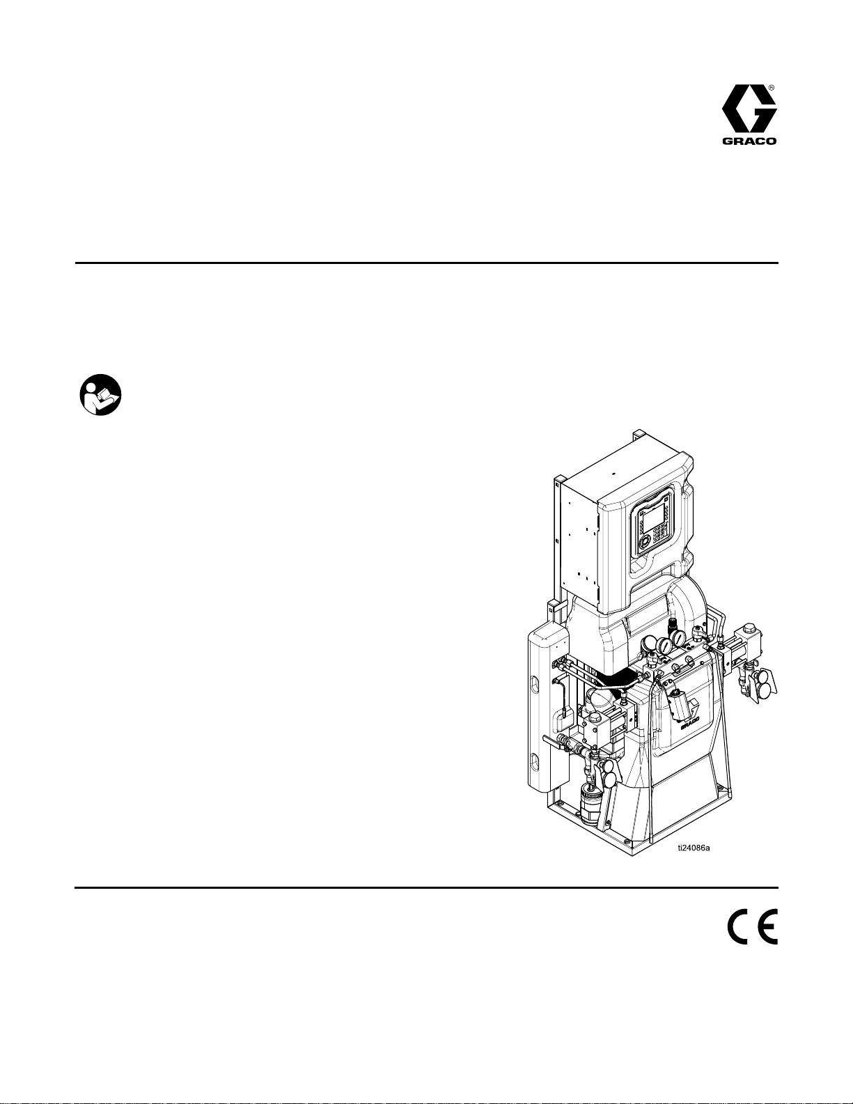
For model information, see page 9.
Heated,
Heated, Heated,
Not
for
Not Not
for for
for
for for
Important
Important Important
Readallwarningsandinstructionsinthismanual.
Save
Save Save
Safety
Safety Safety
these
these these
2
2 2
Plural
Plural Plural
outdoor
outdoor outdoor
use
use use
instructions.
instructions. instructions.
Component
Component Component
use.
use. use.
explosive
in ininexplosive explosive
Instructions
Instructions Instructions
Hydraulic
Hydraulic Hydraulic
Systems
Systems Systems
Proportioner
Proportioner Proportioner
For
professional
For For
professional professional
atmospheres
atmospheres atmospheres
for
spraying
for for
spraying spraying
use
only.
use use
only. only.
or
hazardous
or or
hazardous hazardous
polyurethane
polyurethane polyurethane
locations.
locations. locations.
foam
foam foam
334945B
EN
and
polyurea
and and
polyurea polyurea
PROVENQUALITY.LEADINGTECHNOLOGY.
Page 2

Contents
Contents Contents
Warnings...........................................................3
ImportantIsocyanateInformation.........................7
Models...............................................................9
Approvals...........................................................15
Accessories........................................................15
SuppliedManuals...............................................16
RelatedManuals................................................16
TypicalInstallation,withoutcirculation..................17
TypicalInstallation,withsystemuidmanifold
todrumcirculation.................................18
TypicalInstallation,withgunuidmanifoldto
drumcirculation.....................................19
ComponentIdentication.....................................20
AdvancedDisplayModule(ADM)..................22
ElectricalEnclosure......................................26
HydraulicControlModule(HCM)...................27
TemperatureControlModule(TCM)Cable
Connections...................................28
Setup.................................................................29
Grounding...................................................29
GeneralEquipmentGuidelines.....................29
ConnectPower............................................30
LubricationSystemSetup.............................31
InstallFluidTemperatureSensor..................31
InstallHeatedHosetoProportioner...............31
AdvancedDisplayModule(ADM)
Operation..............................................32
AdvancedSetupScreens.............................35
System1.....................................................36
System2.....................................................36
System3.....................................................36
Recipes.......................................................37
RunMode...................................................38
Startup...............................................................44
FluidCirculation..................................................47
CirculationThroughReactor.........................47
CirculationThroughGunManifold.................48
Spraying............................................................49
SprayAdjustments.......................................50
ManualHoseHeatMode..............................51
Standby.............................................................53
Shutdown...........................................................54
PressureReliefProcedure..................................55
Flushing.............................................................56
Maintenance......................................................57
PreventativeMaintenanceSchedule.............57
ProportionerMaintenance............................57
FlushInletStrainerScreen...........................58
PumpLubricationSystem.............................59
Errors................................................................60
ViewErrors..................................................60
TroubleshootErrors.....................................60
ErrorCodesandTroubleshooting........................61
USBData....................................................61
USBLogs....................................................61
SystemCongurationSettings......................62
CustomLanguageFile.................................63
UploadProcedure........................................63
PerformanceCharts............................................64
TechnicalSpecications......................................66
Notes...............................................................68
Dimensions........................................................69
GracoExtendedWarranty...................................70
2
334945B
Page 3
Warnings
Warnings Warnings
Thefollowingwarningsareforthesetup,use,grounding,maintenance,andrepairofthisequipment.The
exclamationpointsymbolalertsyoutoageneralwarningandthehazardsymbolsrefertoprocedure-specic
risks.Whenthesesymbolsappearinthebodyofthismanualoronwarninglabels,referbacktothese
Warnings.Product-specichazardsymbolsandwarningsnotcoveredinthissectionmayappearthroughout
thebodyofthismanualwhereapplicable.
WARNING
WARNING WARNING
ELECTRIC
ELECTRIC ELECTRIC
Thisequipmentmustbegrounded.Impropergrounding,setup,orusageofthesystemcan
causeelectricshock.
•Turnoffanddisconnectpoweratmainswitchbeforedisconnectinganycablesandbefore
servicingorinstallingequipment.
•Connectonlytogroundedpowersource.
•Allelectricalwiringmustbedonebyaqualiedelectricianandcomplywithalllocalcodes
andregulations.
•Donotexposetorain.Storeindoors.
TOXIC
TOXIC TOXIC
Toxicuidsorfumescancauseseriousinjuryordeathifsplashedintheeyesoronskin,
inhaledorswallowed.
SHOCK
SHOCK SHOCK
FLUID
FLUID FLUID
HAZARD
HAZARD HAZARD
OR
FUMES
OR OR
FUMES FUMES
Warnings
•ReadSafetyDataSheet(SDS)forhandlinginstructionsandtoknowthespecichazardsof
theuidsyouareusing,includingtheeffectsoflong-termexposure.
•Whenspraying,servicingequipment,orwhenintheworkarea,alwayskeepworkarea
wellventilatedandalwayswearappropriatepersonalprotectiveequipment.SeePersonal Personal
Protective
Protective Protective
•Storehazardousuidinapprovedcontainers,anddisposeofitaccordingtoapplicable
guidelines.
PERSONAL
PERSONAL PERSONAL
Alwayswearappropriatepersonalprotectiveequipmentandcoverallskinwhenspraying,
servicingequipment,orwhenintheworkarea.Protectiveequipmenthelpspreventserious
injury,includinglong-termexposure;inhalationoftoxicfumes,mistsorvapors;allergicreaction;
burns;eyeinjuryandhearingloss.Thisprotectiveequipmentincludesbutisnotlimitedto:
•Aproperlyttingrespirator,whichmayincludeasupplied-airrespirator,chemically
impermeablegloves,protectiveclothingandfootcoveringsasrecommendedbytheuid
manufacturerandlocalregulatoryauthority.
•Protectiveeyewearandhearingprotection.
Equipment
Equipment Equipment
PROTECTIVE
PROTECTIVE PROTECTIVE
warningsinthismanual.
EQUIPMENT
EQUIPMENT EQUIPMENT
Personal
334945B 3
Page 4
Warnings
WARNING
WARNING WARNING
SKIN
INJECTION
SKIN SKIN
INJECTION INJECTION
High-pressureuidfromdispensingdevice,hoseleaks,orrupturedcomponentswillpierce
skin.Thismaylooklikejustacut,butitisaseriousinjurythatcanresultinamputation.Get Get
immediate
immediate immediate
•Engagetriggerlockwhennotspraying.
•Donotpointdispensingdeviceatanyoneoratanypartofthebody.
•Donotputyourhandovertheuidoutlet.
•Donotstopordeectleakswithyourhand,body,glove,orrag.
•FollowthePressure Pressure
checking,orservicingequipment.
•Tightenalluidconnectionsbeforeoperatingtheequipment.
•Checkhosesandcouplingsdaily.Replacewornordamagedpartsimmediately.
FIRE
FIRE FIRE
Flammablefumes,suchassolventandpaintfumes,inwork work
orsolventowingthroughtheequipmentcancausestaticsparking.Tohelppreventreand
explosion:
surgical
surgical surgical
AND
EXPLOSION
AND AND
EXPLOSION EXPLOSION
HAZARD
HAZARD HAZARD
Get
treatment.
treatment. treatment.
Pressure
Relief
Procedure
Relief Relief
Procedure Procedure
HAZARD
HAZARD HAZARD
whenyoustopdispensingandbeforecleaning,
work
area
area area
canigniteorexplode.Paint
•Useequipmentonlyinwellventilatedarea.
•Eliminateallignitionsources;suchaspilotlights,cigarettes,portableelectriclamps,and
plasticdropcloths(potentialstaticsparking).
•Groundallequipmentintheworkarea.SeeGrounding Grounding
•Neversprayorushsolventathighpressure.
•Keepworkareafreeofdebris,includingsolvent,ragsandgasoline.
•Donotplugorunplugpowercords,orturnpowerorlightswitchesonoroffwhenammable
fumesarepresent.
•Useonlygroundedhoses.
•Holdgunrmlytosideofgroundedpailwhentriggeringintopail.Donotusepaillinersunless
theyareanti-staticorconductive.
Stop
•Stop Stop
•Keepaworkingreextinguisherintheworkarea.
THERMAL
THERMAL THERMAL
Fluidssubjectedtoheatinconnedspaces,includinghoses,cancreatearapidriseinpressure
duetothethermalexpansion.Over-pressurizationcanresultinequipmentruptureandserious
injury.
•Openavalvetorelievetheuidexpansionduringheating.
•Replacehosesproactivelyatregularintervalsbasedonyouroperatingconditions.
operation
operation operation
equipmentuntilyouidentifyandcorrecttheproblem.
immediately
immediately immediately
EXPANSION
EXPANSION EXPANSION
ifstaticsparkingoccursoryoufeelashock. ..Donotuse
HAZARD
HAZARD HAZARD
Grounding
instructions.
4
334945B
Page 5

WARNING
WARNING WARNING
PRESSURIZED
PRESSURIZED PRESSURIZED
Useofuidsthatareincompatiblewithaluminuminpressurizedequipmentcancauseserious
chemicalreactionandequipmentrupture.Failuretofollowthiswarningcanresultindeath,
seriousinjury,orpropertydamage.
•Donotuse1,1,1-trichloroethane,methylenechloride,otherhalogenatedhydrocarbon
solventsoruidscontainingsuchsolvents.
•Manyotheruidsmaycontainchemicalsthatcanreactwithaluminum.Contactyourmaterial
supplierforcompatibility.
PLASTIC
PLASTIC PLASTIC
Manysolventscandegradeplasticpartsandcausethemtofail,whichcouldcauseserious
injuryorpropertydamage.
•Useonlycompatiblewater-basedsolventstocleanplasticstructuralorpressure-containing
parts.
•SeeTechnical Technical
Technical
solventmanufacturer’sMSDSsandrecommendations.
ALUMINUM
ALUMINUM ALUMINUM
PARTS
PARTS PARTS
CLEANING
CLEANING CLEANING
Data
Data Data
PARTS
PARTS PARTS
SOLVENT
SOLVENT SOLVENT
inthisandallotherequipmentinstructionmanuals.Readuidand
HAZARD
HAZARD HAZARD
HAZARD
HAZARD HAZARD
Warnings
334945B 5
Page 6
Warnings
WARNING
WARNING WARNING
EQUIPMENT
EQUIPMENT EQUIPMENT
Misusecancausedeathorseriousinjury.
•Donotoperatetheunitwhenfatiguedorundertheinuenceofdrugsoralcohol.
•Donotexceedthemaximumworkingpressureortemperatureratingofthelowestrated
systemcomponent.SeeTechnical Technical
•Useuidsandsolventsthatarecompatiblewithequipmentwettedparts.SeeTechnicalData
inallequipmentmanuals.Readuidandsolventmanufacturer’swarnings.Forcomplete
informationaboutyourmaterial,requestMSDSfromdistributororretailer.
•Donotleavetheworkareawhileequipmentisenergizedorunderpressure.
•TurnoffallequipmentandfollowthePressure Pressure
•Checkequipmentdaily.Repairorreplacewornordamagedpartsimmediatelywithgenuine
manufacturer’sreplacementpartsonly.
•Donotalterormodifyequipment.Alterationsormodicationsmayvoidagencyapprovals
andcreatesafetyhazards.
•Makesureallequipmentisratedandapprovedfortheenvironmentinwhichyouareusingit.
•Useequipmentonlyforitsintendedpurpose.Callyourdistributorforinformation.
•Routehosesandcablesawayfromtrafcareas,sharpedges,movingparts,andhotsurfaces.
•Donotkinkoroverbendhosesorusehosestopullequipment.
•Keepchildrenandanimalsawayfromworkarea.
•Complywithallapplicablesafetyregulations.
MOVING
MOVING MOVING
MISUSE
MISUSE MISUSE
PARTS
PARTS PARTS
HAZARD
HAZARD HAZARD
Technical
HAZARD
HAZARD HAZARD
Data
Data Data
Pressure
inallequipmentmanuals.
Relief
Relief Relief
Procedure
Procedure Procedure
whenequipmentisnotinuse.
Movingpartscanpinch,cutoramputatengersandotherbodyparts.
•Keepclearofmovingparts.
•Donotoperateequipmentwithprotectiveguardsorcoversremoved.
•Pressurizedequipmentcanstartwithoutwarning.Beforechecking,moving,orservicing
equipment,followthePressure Pressure
BURN
BURN BURN
Equipmentsurfacesanduidthatisheatedcanbecomeveryhotduringoperation.Toavoid
severeburns:
•Donottouchhotuidorequipment.
HAZARD
HAZARD HAZARD
Pressure
Relief
Procedure
Relief Relief
Procedure Procedure
anddisconnectallpowersources.
6 334945B
Page 7
ImportantIsocyanateInformation
Important
Important Important
Isocyanates(ISO)arecatalystsusedintwocomponentmaterials.
Isocyanate
Isocyanate Isocyanate
Sprayingordispensinguidsthatcontainisocyanatescreatespotentiallyharmfulmists,vapors,and
atomizedparticulates.
•Readandunderstandtheuidmanufacturer’swarningsandSafetyDataSheet(SDS)toknowspecic
hazardsandprecautionsrelatedtoisocyanates.
•Useofisocyanatesinvolvespotentiallyhazardousprocedures.Donotspraywiththisequipmentunless
youaretrained,qualied,andhavereadandunderstoodtheinformationinthismanualandintheuid
manufacturer’sapplicationinstructionsandSDS.
•Useofincorrectlymaintainedormis-adjustedequipmentmayresultinimproperlycuredmaterial,which
couldcauseoffgassingandoffensiveodors.Equipmentmustbecarefullymaintainedandadjusted
accordingtoinstructionsinthemanual.
•Topreventinhalationofisocyanatemists,vaporsandatomizedparticulates,everyoneintheworkarea
mustwearappropriaterespiratoryprotection.Alwayswearaproperlyttingrespirator,whichmayinclude
asupplied-airrespirator.Ventilatetheworkareaaccordingtoinstructionsintheuidmanufacturer’sSDS.
Isocyanate
Isocyanate Isocyanate
Conditions
Conditions Conditions
Information
Information Information
•Avoidallskincontactwithisocyanates.Everyoneintheworkareamustwearchemicallyimpermeable
gloves,protectiveclothingandfootcoveringsasrecommendedbytheuidmanufacturerandlocal
regulatoryauthority.Followalluidmanufacturerrecommendations,includingthoseregardinghandlingof
contaminatedclothing.Afterspraying,washhandsandfacebeforeeatingordrinking.
•Hazardfromexposuretoisocyanatescontinuesafterspraying.Anyonewithoutappropriatepersonal
protectiveequipmentmuststayoutoftheworkareaduringapplicationandafterapplicationforthetime
periodspeciedbytheuidmanufacturer.Generallythistimeperiodisatleast24hours.
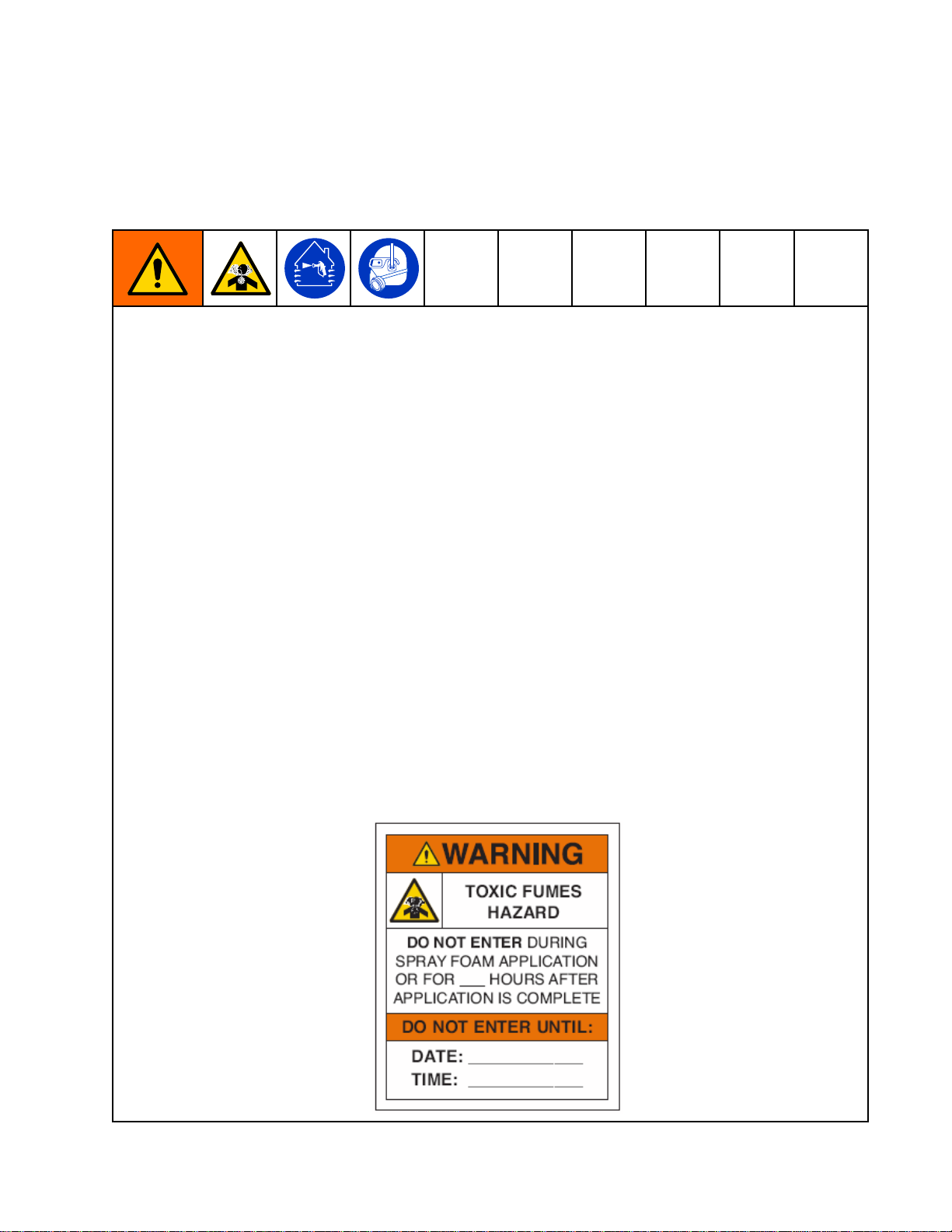
•Warnotherswhomayenterworkareaofhazardfromexposuretoisocyanates.Followthe
recommendationsoftheuidmanufacturerandlocalregulatoryauthority.Postingaplacardsuchasthe
followingoutsidetheworkareaisrecommended:
334945B
7
Page 8

ImportantIsocyanateInformation
Material
Material Material
Somematerialsmaybecomeself-ignitingifapplied
toothick.Readmaterialmanufacturer’swarnings
andSDS.
Keep
Keep Keep
Cross-contaminationcanresultincured
materialinuidlineswhichcouldcauseserious
injuryordamagetoequipment.Toprevent
cross-contamination:
Never
•Never Never
Bwettedparts.
•Neverusesolventononesideifithasbeen
contaminatedfromtheotherside.
Self
Ignition
Self Self
- --Ignition Ignition
Components
Components Components
interchangecomponentAandcomponent
A
and
A A
and and
Moisture
Moisture Moisture
Exposuretomoisture(suchashumidity)willcause
ISOtopartiallycure,formingsmall,hard,abrasive
crystalsthatbecomesuspendedintheuid.
EventuallyalmwillformonthesurfaceandtheISO
willbegintogel,increasinginviscosity.
B
Separate
B B
Separate Separate
PartiallycuredISOwillreduceperformanceand
thelifeofallwettedparts.
•Alwaysuseasealedcontainerwithadesiccant
dryerinthevent,oranitrogenatmosphere.
Never
Never Never
•KeeptheISOpumpwetcuporreservoir(if
installed)lledwithappropriatelubricant.The
lubricantcreatesabarrierbetweentheISOand
theatmosphere.
•Useonlymoisture-proofhosescompatiblewith
ISO.
•Neverusereclaimedsolvents,whichmay
containmoisture.Alwayskeepsolvent
containersclosedwhennotinuse.
Sensitivity
Sensitivity Sensitivity
storeISOinanopencontainer.
of
Isocyanates
of of
Isocyanates Isocyanates
NOTICE
NOTICE NOTICE
Changing
Changing Changing
Changingthematerialtypesusedinyour
equipmentrequiresspecialattentiontoavoid
equipmentdamageanddowntime.
•Whenchangingmaterials,ushtheequipment
multipletimestoensureitisthoroughlyclean.
•Alwayscleantheuidinletstrainersafter
ushing.
•Checkwithyourmaterialmanufacturerfor
chemicalcompatibility.
•Whenchangingbetweenepoxiesandurethanes
orpolyureas,disassembleandcleanalluid
componentsandchangehoses.Epoxiesoften
haveaminesontheB(hardener)side.Polyureas
oftenhaveaminesontheB(resin)side.
Materials
Materials Materials
NOTICE
NOTICE NOTICE
•Alwayslubricatethreadedpartswithan
appropriatelubricantwhenreassembling.
NOTE:
NOTE: NOTE:
crystallizationvariesdependingontheblendofISO,
thehumidity,andthetemperature.
Foam
Foam Foam
Agents
Agents Agents
Somefoamblowingagentswillfrothattemperatures
above90°F(33°C)whennotunderpressure,
especiallyifagitated.Toreducefrothing,minimize
preheatinginacirculationsystem.
Theamountoflmformationandrateof
Resins
Resins Resins
with
245
fa
with with
245 245
Blowing
fa fa
Blowing Blowing
8 334945B
Page 9

Models
Models
Models Models
Reactor
Reactor Reactor
Model
Model Model
Proportioner
Proportioner Proportioner
Maximum
Maximum Maximum
Pressure
Pressure Pressure
Approximate
Approximate Approximate
(A+B)
gal.
(A+B) (A+B)
gal. gal.
Max
Flow
Max Max
Flow Flow
Total
System
Total Total
System System
Congurable
Congurable Congurable
Full
Load
Full Full
Load Load
Fusion
Fusion Fusion
®AP AP
(Gun Part No.)
Fusion
Fusion Fusion
®CS CS
(Gun Part No.)
Probler
Probler Probler
(Gun Part No.)
Heated
50
(15
50 50
ft ftft(15 (15
24K240(scuffguard)
24Y240(Xtreme-wrap)
Heated
Heated Heated
10
10 10
ft ftft(3 (3(3m) m)
Graco
Insite
Graco Graco
Insite Insite
Fluid
Inlet
Fluid Fluid
Inlet Inlet
30
2 22H HH- --30 30
★17H03117H03217H13117H132
Fluid
Working
Fluid Fluid
Working Working
psi
(MPa,
psi psi
(MPa, (MPa,
Output
Output Output
(liter)
(liter) (liter)
Rate
lb/min
Rate Rate
lb/min lb/min
Load
Load Load
Voltage
Voltage Voltage
Peak
Current*
Peak Peak
Current* Current*
AP
Package
Package Package
CS
Package
Package Package
P2
Package
P2 P2
Package Package
Hose
Hose Hose
m)
m) m)
Whip
Hose
Whip Whip
Hose Hose
m)
Sensors
Sensors Sensors
and
and and
bar)
bar) bar)
per
Cycle
per per
Cycle Cycle
(kg/min)
(kg/min) (kg/min)
(Watts)
† ††(Watts) (Watts)
Phase
Phase Phase
6
6
6
(2)
(2) (2)
30
H HH- --30 30
10
kW
10 10
kW kW
2000(14,140)2000(14,140)2000(14,140)2000(14,140)
0.073(0.28)0.073(0.28)0.073(0.28)0.073(0.28)
28(12.7)28(12.7)28(12.7)28(12.7)
17,96023,26017,96023,260
230
1Ø
79463510059357946351005935
APH031
(246102)
CSH031
(CS02RD)
P2H031
(GCP2R2)
24K24024K24024K24024K24024Y24024Y24024Y24024Y240 Heated Heated
Qty:1Qty:5Qty:1Qty:5Qty:1Qty:5Qty:1Qty:5
246050246050246050246050
Elite
Elite Elite
30
Model
H HH- --30 30
Model Model
15
kW
15 15
kW kW
230
3Ø∆
380
3ØY
AHH031
(246102)
CHH031
(CS02RD)
PHH031
(GCP2R2)
230
1Ø
APH032
(246102)
CSH032
(CS02RD)
P2H032
(GCP2R2)
230
3Ø∆
380
3ØY
AHH032
(246102)
CHH032
(CS02RD)
PHH032
(GCP2R2)
kW
10 1010kW kW
230
1Ø
APH131
(246102)
CSH131
(CS02RD)
P2H131
(GCP2R2)
✓✓
✓✓
30
Elite
H HH- --30 30
230
3Ø∆
380
3ØY
AHH131
(246102)
CHH131
(CS02RD)
PHH131
(GCP2R2)
Model
Elite Elite
Model Model
kW
15 1515kW kW
230
1Ø
APH132
(246102)
CSH132
(CS02RD)
P2H132
(GCP2R2)
230
3Ø∆
380
3ØY
AHH132
(246102)
CHH132
(CS02RD)
PHH132
(GCP2R2)
*
Fullloadampswithalldevicesoperatingat
* *
maximumcapabilities.Fuserequirements
atvariousowratesandmixchambersizes
maybeless.
=
Totalsystemwattsusedbysystem,basedon
maximumheatedhoselengthforeachunit.
•H–30series:310ft(94.5m)maximum
heatedhoselength,includingwhiphose.
★
SeeApprovals,page15.
6
Packagesincludegun,heatedhose,and
whiphose.Elitepackagesalsoinclude
GracoInSiteanduidinletsensors.AllElite
hoseandgunsystempackagesinclude
Xtreme-Wrap™50ft(15m)heatedhose.
Forpartnumbers,seeAccessories,page15.
Voltage
Voltage Voltage
Ø
∆
Congurations
Congurations Congurations
Key
Key Key
PHASE
DELTA
YWYE
334945B 9
Page 10

Models
Reactor
Reactor Reactor
Model
Model Model
Proportioner
Proportioner Proportioner
Maximum
Maximum Maximum
Pressure
Pressure Pressure
Approximate
Approximate Approximate
(A+B)
gal.
(A+B) (A+B)
gal. gal.
Max
Flow
Max Max
Flow Flow
Total
System
Total Total
System System
Voltage
Voltage Voltage
Full
Load
Full Full
Load Load
Fusion
Fusion Fusion
®AP AP
(Gun Part No.)
Fusion
Fusion Fusion
®CS CS
(Gun Part No.)
Probler
Probler Probler
(Gun Part No.)
Heated
(15
50 5050ft ftft(15 (15
24K240(scuffguard)
24Y240(Xtreme-wrap)
Heated
Heated Heated
10 1010ft ftft(3 (3(3m) m)
Graco
Insite
Graco Graco
Insite Insite
Fluid
Inlet
Fluid Fluid
Inlet Inlet
H
40
2 22H H
★17H04317H04417H14317H144
Fluid
Working
Fluid Fluid
Working Working
psi
(MPa,
psi psi
(MPa, (MPa,
Output
Output Output
(liter)
(liter) (liter)
Rate
lb/min
Rate Rate
lb/min lb/min
Load
Load Load
Phase
Phase Phase
Peak
Current*
Peak Peak
Current* Current*
AP
Package
Package Package
CS
Package
Package Package
P2
Package
P2 P2
Package Package
Hose
Hose Hose
m)
m) m)
Whip
Hose
Whip Whip
Hose Hose
m)
Sensors
Sensors Sensors
and
- --40 40
and and
bar)
bar) bar)
per
Cycle
per per
Cycle Cycle
(kg/min)
(kg/min) (kg/min)
(Watts)
† ††(Watts) (Watts)
6
6
6
(2)
(2) (2)
40
H HH- --40 40
15
kW
15 15
kW kW
2000(14,140)2000(14,140)2000(14,140)2000(14,140)
0.063(0.24)0.063(0.24)0.063(0.24)0.063(0.24)
45(20)45(20)45(20)45(20)
26,60031,70026,60031,700
2303Ø∆2303Ø∆2303Ø∆2303Ø∆
71957195
APH043
(246102)
CSH043
(CS02RD)
P2H043
(GCP2R2)
24K24024K24024K24024K24024Y24024Y24024Y24024Y240 Heated Heated
Qty:1Qty:5Qty:1Qty:5Qty:1Qty:5Qty:1Qty:5
246050246050246050246050
Elite
Elite Elite
40
Model
H HH- --40 40
Model Model
20
kW
20 20
kW kW
AHH043
(246102)
CHH043
(CS02RD)
PHH043
(GCP2R2)
APH044
(246102)
CSH044
(CS02RD)
P2H044
(GCP2R2)
AHH044
(246102)
CHH044
(CS02RD)
PHH044
(GCP2R2)
kW
15 1515kW kW
APH143
(246102)
CSH143
(CS02RD)
P2H143
(GCP2R2)
✓✓
✓✓
40
Elite
H HH- --40 40
AHH143
(246102)
CHH143
(CS02RD)
PHH143
(GCP2R2)
Model
Elite Elite
Model Model
kW
20 2020kW kW
APH144
(246102)
CSH144
(CS02RD)
P2H144
(GCP2R2)
AHH144
(246102)
CHH144
(CS02RD)
PHH144
(GCP2R2)
*
Fullloadampswithalldevicesoperatingat
* *
maximumcapabilities.Fuserequirements
atvariousowratesandmixchambersizes
maybeless.
=
Totalsystemwattsusedbysystem,basedon
maximumheatedhoselengthforeachunit.
•H–40series:410ft(125m)maximum
heatedhoselength,includingwhiphose.
★
SeeApprovals,page15.
6
Packagesincludegun,heatedhose,and
whiphose.Elitepackagesalsoinclude
GracoInSiteanduidinletsensors.AllElite
hoseandgunsystempackagesinclude
Xtreme-Wrap™50ft(15m)heatedhose.
Forpartnumbers,seeAccessories,page15.
Voltage
Voltage Voltage
Ø
∆
Congurations
Congurations Congurations
Key
Key Key
PHASE
DELTA
YWYE
10 334945B
Page 11

Models
Reactor
Reactor Reactor
(Continued)
(Continued) (Continued)
Model
Model Model
Proportioner
Proportioner Proportioner
Maximum
Maximum Maximum
Pressure
Pressure Pressure
Approximate
Approximate Approximate
(A+B)
gal.
(A+B) (A+B)
gal. gal.
Max
Flow
Max Max
Flow Flow
Total
System
Total Total
System System
Voltage
Voltage Voltage
Full
Load
Full Full
Load Load
Fusion
Fusion Fusion
®AP AP
(Gun Part No.)
Fusion
Fusion Fusion
®CS CS
(Gun Part No.)
Probler
Probler Probler
(Gun Part No.)
Heated
50
(15
50 50
ft ftft(15 (15
24K240(scuffguard)
24Y240(Xtreme-wrap)
Heated
Heated Heated
10
10 10
ft ftft(3 (3(3m) m)
Graco
Insite
Graco Graco
Insite Insite
Fluid
Inlet
Fluid Fluid
Inlet Inlet
2
40
2 2
H HH- --40 40
★17H04517H04617H14517H146
Fluid
Working
Fluid Fluid
Working Working
psi
(MPa,
psi psi
(MPa, (MPa,
Output
Output Output
(liter)
(liter) (liter)
Rate
lb/min
Rate Rate
lb/min lb/min
Load
Load Load
† ††(Watts) (Watts)
Phase
Phase Phase
Peak
Current*
Peak Peak
Current* Current*
AP
Package
Package Package
CS
Package
Package Package
P2
Package
P2 P2
Package Package
Hose
Hose Hose
m)
m) m)
Whip
Hose
Whip Whip
Hose Hose
m)
Sensors
Sensors Sensors
(2)
(2) (2)
and
and and
bar)
bar) bar)
per
Cycle
per per
Cycle Cycle
(kg/min)
(kg/min) (kg/min)
(Watts)
6
6
6
40
H HH- --40 40
15
kW
15 15
kW kW
2000(14,140)2000(14,140)2000(14,140)2000(14,140)
0.063(0.24)0.063(0.24)0.063(0.24)0.063(0.24)
45(20)45(20)45(20)45(20)
26,60031,70026,60031,700
3803Ø∆3803Ø∆3803Ø∆3803Ø∆
41524152
APH045
(246102)
CSH045
(CS02RD)
P2H045
(GCP2R2)
24K24024K24024K24024K24024Y24024Y24024Y24024Y240 Heated Heated
Qty:1Qty:5Qty:1Qty:5Qty:1Qty:5Qty:1Qty:5
246050246050246050246050
Elite
Elite Elite
40
Model
H HH- --40 40
Model Model
20
kW
20 20
kW kW
AHH045
(246102)
CHH045
(CS02RD)
PHH045
(GCP2R2)
APH046
(246102)
CSH046
(CS02RD)
P2H046
(GCP2R2)
AHH046
(246102)
CHH046
(CS02RD)
PHH046
(GCP2R2)
kW
15 1515kW kW
APH145
(246102)
CSH145
(CS02RD)
P2H145
(GCP2R2)
✓✓
✓✓
40
Elite
H HH- --40 40
AHH145
(246102)
CHH145
(CS02RD)
PHH145
(GCP2R2)
Model
Elite Elite
Model Model
kW
20 2020kW kW
APH146
(246102)
CSH146
(CS02RD)
P2H146
(GCP2R2)
AHH146
(246102)
CHH146
(CS02RD)
PHH146
(GCP2R2)
*
Fullloadampswithalldevicesoperatingat
* *
maximumcapabilities.Fuserequirements
atvariousowratesandmixchambersizes
maybeless.
=
Totalsystemwattsusedbysystem,basedon
maximumheatedhoselengthforeachunit.
•H–40series:410ft(125m)maximum
heatedhoselength,includingwhiphose.
★
SeeApprovals,page15.
6
Packagesincludegun,heatedhose,and
whiphose.Elitepackagesalsoinclude
GracoInSiteanduidinletsensors.AllElite
hoseandgunsystempackagesinclude
Xtreme-Wrap™50ft(15m)heatedhose.
Forpartnumbers,seeAccessories,page15.
Voltage
Voltage Voltage
Ø
∆
Congurations
Congurations Congurations
Key
Key Key
PHASE
DELTA
YWYE
334945B
11
Page 12

Models
Reactor
Reactor Reactor
Model
Model Model
Proportioner
Proportioner Proportioner
Maximum
Maximum Maximum
Pressure
Pressure Pressure
Approximate
Approximate Approximate
(A+B)
gal.
(A+B) (A+B)
gal. gal.
Max
Flow
Max Max
Flow Flow
Total
System
Total Total
System System
Congurable
Congurable Congurable
Full
Load
Full Full
Load Load
Fusion
Fusion Fusion
®AP AP
(Gun Part No.)
Fusion
Fusion Fusion
®CS CS
(Gun Part No.)
Probler
Probler Probler
(Gun Part No.)
Heated
(15
50 5050ft ftft(15 (15
24K240(scuffguard)
24Y240(Xtreme-wrap)
Heated
Heated Heated
10 1010ft ftft(3 (3(3m) m)
Graco
Insite
Graco Graco
Insite Insite
Fluid
Inlet
Fluid Fluid
Inlet Inlet
H
50
2 22H H
★17H05317H05617H15317H156
Fluid
Working
Fluid Fluid
Working Working
psi
(MPa,
psi psi
(MPa, (MPa,
Output
Output Output
(liter)
(liter) (liter)
Rate
lb/min
Rate Rate
lb/min lb/min
Load
Load Load
Voltage
Voltage Voltage
Peak
Current*
Peak Peak
Current* Current*
AP
Package
Package Package
CS
Package
Package Package
P2
Package
P2 P2
Package Package
Hose
Hose Hose
m)
m) m)
Whip
Hose
Whip Whip
Hose Hose
m)
Sensors
Sensors Sensors
and
- --50 50
and and
bar)
bar) bar)
per
Cycle
per per
Cycle Cycle
(kg/min)
(kg/min) (kg/min)
(Watts)
† ††(Watts) (Watts)
Phase
Phase Phase
6
6
6
(2)
(2) (2)
50
H HH- --50 50
20
kW
20 20
kW kW
2000(14,140)2000(14,140)2000(14,140)2000(14,140)
0.073(0.28)0.073(0.28)0.073(0.280.073(0.28
52(24)52(24)52(24)52(24)
31,70031,70031,70031,700
2303Ø∆3803ØY2303Ø∆3803ØY
95529552
APH053
(246102)
CSH053
(CS02RD)
P2H053
(GCP2R2)
24K24024K24024K24024K24024Y24024Y24024Y24024Y240 Heated Heated
Qty:1Qty:5Qty:1Qty:5Qty:1Qty:5Qty:1Qty:5
246050246050246050246050
Elite
Elite Elite
50
Model
H HH- --50 50
Model Model
20
kW
20 20
kW kW
AHH053
(246102)
CHH053
(CS02RD)
PHH053
(GCP2R2)
APH056
(246102)
CSH056
(CS02RD)
P2H056
(GCP2R2)
AHH056
(246102)
CHH056
(CS02RD)
PHH056
(GCP2R2)
kW
20 2020kW kW
APH153
(246102)
CSH153
(CS02RD)
P2H153
(GCP2R2)
✓✓
✓✓
50
Elite
H HH- --50 50
AHH153
(246102)
CHH153
(CS02RD)
PHH153
(GCP2R2)
Model
Elite Elite
Model Model
kW
20 2020kW kW
APH156
(246102)
CSH156
(CS02RD)
P2H156
(GCP2R2)
AHH156
(246102)
CHH156
(CS02RD)
PHH156
(GCP2R2)
*
Fullloadampswithalldevicesoperatingat
* *
maximumcapabilities.Fuserequirements
atvariousowratesandmixchambersizes
maybeless.
=
Totalsystemwattsusedbysystem,basedon
maximumheatedhoselengthforeachunit.
•H–50series:410ft(125m)maximum
heatedhoselength,includingwhiphose.
★
SeeApprovals,page15.
6
Packagesincludegun,heatedhose,and
whiphose.Elitepackagesalsoinclude
GracoInSiteanduidinletsensors.AllElite
hoseandgunsystempackagesinclude
Xtreme-Wrap™50ft(15m)heatedhose.
Forpartnumbers,seeAccessories,page15.
Voltage
Voltage Voltage
Ø
∆
Congurations
Congurations Congurations
Key
Key Key
PHASE
DELTA
YWYE
12
334945B
Page 13

Models
Reactor
Reactor Reactor
Model
Model Model
Proportioner
Proportioner Proportioner
Maximum
Maximum Maximum
Pressure
Pressure Pressure
Approximate
Approximate Approximate
(A+B)
(A+B) (A+B)
Max
Max Max
Total
Total Total
Congurable
Congurable Congurable
Full
Full Full
Fusion
Fusion Fusion
(Gun Part No.)
Probler
Probler Probler
(Gun Part No.)
Heated
Heated Heated
50
50 50
Heated
Heated Heated
10
10 10
Graco
Graco Graco
Fluid
Fluid Fluid
XP2
2 22H HH- --XP2 XP2
★17H06217H162
Fluid
Working
Fluid Fluid
Working Working
psi
(MPa,
psi psi
gal.
(liter)
gal. gal.
(liter) (liter)
Flow
Rate
Flow Flow
Rate Rate
System
System System
Load
Peak
Load Load
Peak Peak
AP
®AP AP
P2
Package
P2 P2
Package Package
Hose
Hose Hose
(15
m)
ft ftft(15 (15
m) m)
Whip
Whip Whip
m)
ft ftft(3 (3(3m) m)
Insite
Insite Insite
Inlet
Sensors
Inlet Inlet
Sensors Sensors
bar)
(MPa, (MPa,
bar) bar)
Output
per
Output Output
per per
lb/min
lb/min lb/min
Load
(Watts)
Load Load
† ††(Watts) (Watts)
Voltage
Phase
Voltage Voltage
Phase Phase
Current*
Current* Current*
Package
Package Package
6
Hose
Hose Hose
(2)
(2) (2)
and
and and
15
15 15
3500(24.1,241)3500(24.1,241)
Cycle
Cycle Cycle
0.042(0.16)0.042(0.16)
(kg/min)
(kg/min) (kg/min)
6
1.5(5.7)1.5(5.7)
23,26023,260
2301Ø2303Ø∆2303ØY2301Ø2303Ø∆2303ØY
10059351005935
APH062
(246101)
P2H062
(GCP2R1)
24K241
(scuffguard)
246055246055
XP2
H HH- --XP2 XP2
kW
kW kW
Elite
Elite Elite
XP2
Model
H HH- --XP2 XP2
Model Model
15kW
15kW 15kW
AHH062
(246101)
PHH062
(246101)
APH162
(246101)
P2H162
(GCP2R1)
24Y241
(Xtreme-wrap)
✓
✓
XP2
Elite
H HH- --XP2 XP2
Model
Elite Elite
Model Model
AHH162
(246101)
PHH162
(246101)
*
Fullloadampswithalldevicesoperatingat
* *
maximumcapabilities.Fuserequirements
atvariousowratesandmixchambersizes
maybeless.
=
Totalsystemwattsusedbysystem,basedon
maximumheatedhoselengthforeachunit.
•H–XP2series:310ft(94.5m)maximum
heatedhoselength,includingwhiphose.
★
SeeApprovals,page15.
6
Packagesincludegun,heatedhose,and
whiphose.Elitepackagesalsoinclude
GracoInSiteanduidinletsensors.AllElite
hoseandgunsystempackagesinclude
Xtreme-Wrap™50ft(15m)heatedhose.
Forpartnumbers,seeAccessories,page15.
Voltage
Voltage Voltage
Ø
∆
Congurations
Congurations Congurations
Key
Key Key
PHASE
DELTA
YWYE
334945B 13
Page 14

Models
Reactor
Reactor Reactor
Model
Model Model
Proportioner
Proportioner Proportioner
Maximum
Maximum Maximum
Pressure
Pressure Pressure
Approximate
Approximate Approximate
(A+B)
gal.
(A+B) (A+B)
gal. gal.
Max
Flow
Max Max
Flow Flow
Total
System
Total Total
System System
Congurable
Congurable Congurable
Full
Load
Full Full
Load Load
Fusion
Fusion Fusion
®AP AP
(Gun Part No.)
Probler
Probler Probler
(Gun Part No.)
Heated
(15
50 5050ft ftft(15 (15
24K240(scuffguard)
24Y240(Xtreme-wrap)
Heated
Heated Heated
10 1010ft ftft(3 (3(3m) m)
Graco
Insite
Graco Graco
Insite Insite
Fluid
Inlet
Fluid Fluid
Inlet Inlet
H
XP3
2 22H H
- --XP3 XP3
★17H07417H07617H17417H176
Fluid
Working
Fluid Fluid
Working Working
psi
(MPa,
psi psi
(liter)
(liter) (liter)
Rate
Rate Rate
Peak
Peak Peak
AP
P2
Package
P2 P2
Package Package
Hose
Hose Hose
m)
m) m)
Whip
Whip Whip
m)
Sensors
Sensors Sensors
bar)
(MPa, (MPa,
bar) bar)
Output
per
Output Output
per per
lb/min
lb/min lb/min
Load
(Watts)
Load Load
† ††(Watts) (Watts)
Voltage
Phase
Voltage Voltage
Phase Phase
Current*
Current* Current*
Package
Package Package
6
Hose
Hose Hose
(2)
(2) (2)
and
H
and and
20
20 20
3500(24.1,241)3500(24.1,241)3500(24.1,241)3500(24.1,241)
Cycle
Cycle Cycle
0.042(0.16)0.042(0.16)0.042(0.16)0.042(0.16)
(kg/min)
(kg/min) (kg/min)
6
2.8(10.6)2.8(10.6)2.8(10.6)2.8(10.6)
31,70031,70031,70031,700
2303Ø∆3803ØY2303Ø∆3803ØY
95529552
APH074
(246102)
P2H074
(GCP2R2)
24K24024K24024K24024K24024Y24024Y24024Y24024Y240 Heated Heated
Qty:1Qty:5Qty:1Qty:5Qty:1Qty:5Qty:1Qty:5
246050246050246050246050
XP3
H H
- --XP3 XP3
kW
kW kW
Elite
Elite Elite
XP3
Model
H HH- --XP3 XP3
Model Model
20
kW
20 20
kW kW
APH074
(246102)
P2H074
(GCP2R2)
APH076
(246102)
P2H076
(GCP2R2)
APH076
(246102)
P2H076
(GCP2R2)
kW
20 2020kW kW
APH174
(246102)
P2H174
(GCP2R2)
✓✓
✓✓
XP3
Elite
H HH- --XP3 XP3
APH174
(246102)
P2H174
(GCP2R2)
Model
Elite Elite
Model Model
kW
20 2020kW kW
APH176
(246102)
P2H176
(GCP2R2)
APH176
(246102)
P2H176
(GCP2R2)
*
Fullloadampswithalldevicesoperatingat
* *
maximumcapabilities.Fuserequirements
atvariousowratesandmixchambersizes
maybeless.
=
Totalsystemwattsusedbysystem,basedon
maximumheatedhoselengthforeachunit.
•H–XP3series:410ft(125m)maximum
heatedhoselength,includingwhiphose.
★
SeeApprovals,page15.
6
Packagesincludegun,heatedhose,and
whiphose.Elitepackagesalsoinclude
GracoInSiteanduidinletsensors.AllElite
hoseandgunsystempackagesinclude
Xtreme-Wrap™50ft(15m)heatedhose.
Forpartnumbers,seeAccessories,page15.
Voltage
Voltage Voltage
Ø
∆
Congurations
Congurations Congurations
Key
Key Key
PHASE
DELTA
YWYE
14
334945B
Page 15

Approvals
Approvals
Approvals Approvals
Intertekapprovalsapplytoproportionerswithout
hoses.
Proportioner
Proportioner Proportioner
ConformstoANSI/ULStd.499
CertiedtoCAN/CSAStd.C22.2No.88
Approvals:
Approvals: Approvals:
9902471
9902471 9902471
Accessories
Accessories Accessories
Kit
Number
Kit Kit
Number Number
24U315
17G340CasterKit
24T280
17F837
16X521
24N449
24K207
24U174RemoteDisplayModuleKit
15V551
15M483RemoteDisplayModuleProtective
24M174
121006
Description
Description Description
AirManifold(4outlets)
GracoInSiteKit
InletSensorKit
GracoInSiteExtensioncable24.6ft
(7.5m)
50ft(15m)CANcable(forremote
displaymodule)
FluidTemperatureSensor(FTS)
withRTD
ADMProtectiveCovers(10pack)
Covers(10pack)
DrumLevelSticks
150ft(45m)CANcable(forremote
displaymodule)
24N365
RTDTestCables(toaideresistance
measurements)
334945B 15
Page 16
SuppliedManuals
Supplied
Supplied Supplied
ThefollowingmanualsareshippedwiththeReactor
2.Refertothesemanualsfordetailedequipment
information.
Manualsarealsoavailableatwww.graco.com.
Manual
Manual Manual
334945Reactor2HydraulicProportioning
334005Reactor2HydraulicProportioning
334006Reactor2HydraulicProportioning
Manuals
Manuals Manuals
Description
Description Description
SystemsOperationManual
SystemsShutdownQuickGuide
SystemsStartupQuickGuide
Related
Related Related
Thefollowingmanualsareforaccessoriesusedwith
theReactor2.
Component
Component Component
Manualsareavailableatwww.graco.com.
System
System System
333946Reactor2Repair-Parts
Displacement
Displacement Displacement
3A3085PumpRepair-Parts
Feed
Feed Feed
309572HeatedHose,Instructions-Parts
309852
309815FeedPumpKits,Instructions-Parts
309827
Spray
Spray Spray
309550
312666
313213
Accessory
Accessory Accessory
3A1905
3A3009
3A1907RemoteDisplayModuleKit,
332735
3A3010
333276
3A3084EliteKit,Instructions-Part
3A3085PumplineRepair,Instructions-Parts
Manuals
Manuals Manuals
System
System System
Gun
Gun Gun
Manuals
Manuals Manuals
Manuals
Manuals Manuals
Pump
Manual
Pump Pump
Manual Manual
Manuals
Manuals Manuals
CirculationandReturnTubeKit,
Instructions-Parts
FeedPumpAirSupplyKit,
Instructions-Parts
Manuals
Manuals Manuals
Fusion™APGun
Fusion™CSGun
Probler
Manuals
Manuals Manuals
FeedPumpShutdownKit,
Instructions-Parts
InletSensorKit,Instructions-Parts
Instructions-Parts
AirManifoldKit,Instructions-Parts
CasterKit,Instructions-Parts
GracoInSite™Kit,Instructions-Parts
®
P2Gun
in
English:
in in
English: English:
16 334945B
Page 17
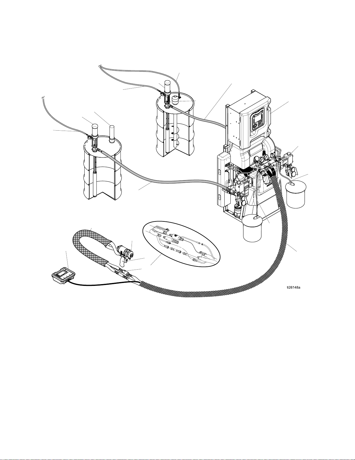
TypicalInstallation,withoutcirculation
B
G
K
M
J
G
H
K
L
J
D
S
C*
P
E
A
N
(B-RES)
(A-ISO)
F
N
Typical
Typical Typical
Installation,
Installation, Installation,
without
without without
circulation
circulation circulation
Figure1
*Shownexposedforclarity.Wrapwithtapeduringoperation.
AReactorProportioner
BHeatedHose
CFluidTemperatureSensor(FTS)
DHeatedWhipHose
E
F
GFeedPumpAirSupplyLines
H
FusionSprayGun
GunAirSupplyHose
AgitatorAirSupplyLine
J
KFeedPumps
LAgitator
MDesiccantDryer
NBleedLines
P
SRemoteDisplayModuleKit(optional)
FluidSupplyLines
GunFluidManifold(partofgun)
334945B
17
Page 18

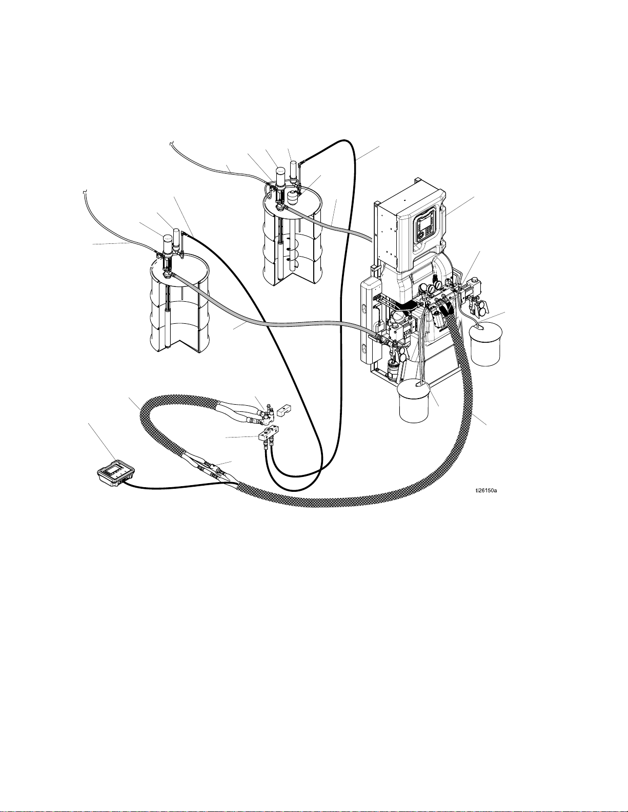
TypicalInstallation,withsystemuidmanifoldtodrumcirculation
(B-RES)
M
K
M
R
J
G
H
K
L
B
D
S
C*
P
E
R
A
(A-ISO)
G
J
F
Typical
Typical Typical
circulation
circulation circulation
Installation,
Installation, Installation,
with
with with
system
system system
uid
uid uid
manifold
manifold manifold
to
drum
to to
drum drum
Figure2
*Shownexposedforclarity.Wrapwithtapeduringoperation.
AReactorProportioner
BHeatedHose
CFluidTemperatureSensor(FTS)
DHeatedWhipHose
E
F
GFeedPumpAirSupplyLines
H
FusionSprayGun
GunAirSupplyHose
AgitatorAirSupplyLine
J
KFeedPumps
LAgitator
MDesiccantDryer
P
RRecirculationLines
SRemoteDisplayModule(optional)
FluidSupplyLines
GunFluidManifold(partofgun)
18 334945B
Page 19
TypicalInstallation,withgunuidmanifoldtodrumcirculation
(B-RES)
M
K
M
R
J
G
H
K
L
B
J
D
S
C*
P
E
R
(A-ISO)
G
A
N
N
F
Typical
Typical Typical
circulation
circulation circulation
Installation,
Installation, Installation,
with
with with
gun
gun gun
uid
uid uid
manifold
manifold manifold
to
drum
to to
drum drum
Figure3
*Shownexposedforclarity.Wrapwithtapeduringoperation.
AReactorProportioner
BHeatedHose
CFluidTemperatureSensor(FTS)
CKCirculationBlock(accessory)
DHeatedWhipHose
F
GFeedPumpAirSupplyLines
H
GunAirSupplyHose
AgitatorAirSupplyLine
J
KFeedPumps
LAgitator
MDesiccantDryer
NBleedLines
P
RRecirculationLines
SRemoteDisplayModule(optional)
FluidSupplyLines
GunFluidManifold(partofgun)
334945B 19
Page 20
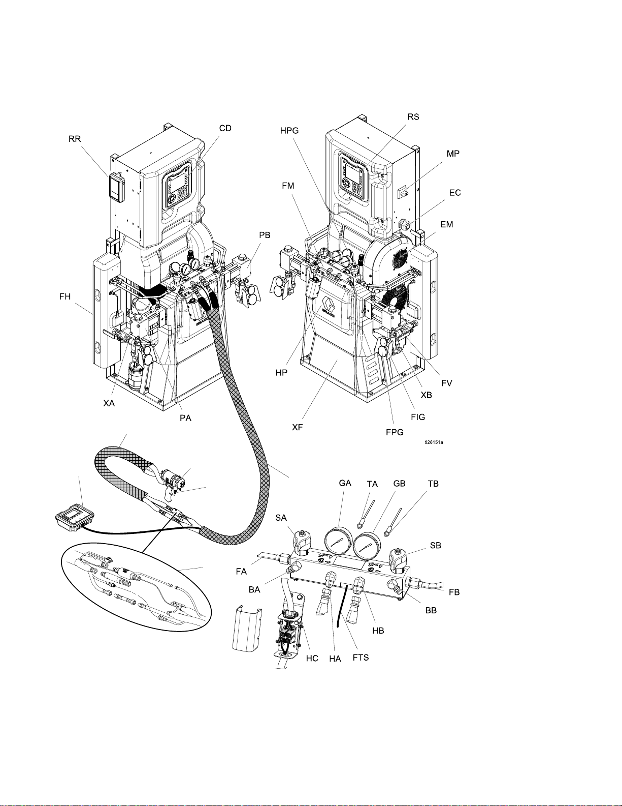
ComponentIdentication
B
D
S
C*
P
E
Component
Component Component
Identication
Identication Identication
Figure4
20 334945B
Page 21

Key
Key Key
BA
BB
CDAdvancedDisplayModule(ADM)
ECElectricalCordStrainRelief
EM
FA
FB
FH
FM
FV
GAISOSidePressureGauge
GBRESSidePressureGauge
HA
HB
HC
HP
MP
PA
PB
ISOSidePressureReliefOutlet
RESSidePressureReliefOutlet
ElectricMotor(behindshroud)
ISOSideFluidManifoldInlet
RESSideFluidManifoldInlet
FluidHeater(behindshroud)
ReactorFluidManifold
FluidInletValve(RESsideshown)
ISOSideHoseConnection
RESSideHoseConnection
HeatedHoseElectricalJunctionBox
HydraulicDriver(behindshroud)
MainPowerSwitch
ISOSidePump
RESSidePump
ComponentIdentication
RR
RSRedStopButton
SAISOSidePRESSURERELIEF/SPRAY
SBRESSidePRESSURERELIEF/SPRAY
TA
TB
XA
XB
XF
FPGFluidInletValvePressureGauge
FTGFluidInletValveTemperatureGauge
FTSFTSConnection
HPGHydraulicPressureGauge
GracoInSiteCellularModule(Elitemodels
only)
Valve
Valve
ISOSidePressureTransducer(behind
gaugeGA)
RESSidePressureTransducer(behind
gaugeGB)
FluidInletSensor(ISOside,Elitemodels
only)
FluidInletSensor(RESside,Elitemodels
only)
HeatedHoseTransformer(behindcover)
334945B
21
Page 22

ComponentIdentication
Advanced
Advanced Advanced
TheADMdisplayshowsgraphicalandtext
informationrelatedtosetupandsprayoperations.
Figure5ADMFrontView
Topreventdamagetothesoftkeybuttons,donot
pressbuttonswithsharpobjectssuchaspens,
plasticcards,orngernails.
Display
Display Display
Module
Module Module
NOTICE
NOTICE NOTICE
(ADM)
(ADM) (ADM)
Table
Table Table
Key
Key Key
Startup
Startup Startup
Shutdown
Shutdown Shutdown
Key
Key Key
Indicator
Indicator Indicator
Soft
Soft Soft
Navigation
Navigation Navigation
Numeric Numeric
ADM
Keys
and
1 11: ::ADM ADM
and
and and
Stop
Stop Stop
Keys
Keys Keys
Keys
Keys Keys
Numeric
Keypad
Keypad Keypad
Keys Keys
Function
Function Function
Presstostartuporshutdownthe
system.
/
/ /
Presstostopallproportioner
processes.Thisisnotasafetyor
emergencystop.
Presstoselectthespecicscreen
oroperationshownonthedisplay
directlynexttoeachkey.
Left/Right Arrows:
•
fromscreentoscreen.
•
Up/Down Arrows:
amongeldsonascreen,items
onadropdownmenu,ormultiple
screenswithinafunction.
Usetoinputvalues.
Indicators
and and
Indicators Indicators
Usetomove
Usetomove
Usetocanceladataentryeld.
AlsousedtoreturntoHomescreen.
Cancel
Cancel Cancel
PresstoenterorexitSetupmode.
Setup
Setup Setup
Presstochooseaeldtoupdate,
tomakeaselection,tosavea
selectionorvalue,toenterascreen,
Enter
Enter Enter
22
ortoacknowledgeanevent.
334945B
Page 23

Figure6ADMBackView
CJFlatPanelMount(VESA100)
CKModelandSerialNumber
CLUSBPortandStatusLEDs
CMCANCommunicationCableConnection
CNModuleStatusLEDs
CPAccessoryCableConnection
CRTokenAccessCover
CSBackupBatteryAccessCover
ComponentIdentication
Table
Table Table
LED
LED LED
System
System System
USB
USB USB
ADM
ADM ADM
ADM
LED
2 22ADM ADM
Status
Status Status
Status
Status Status
Status
Status Status
Status
LED LED
Status Status
(CL)
(CL) (CL)
(CN)
(CN) (CN)
Descriptions
Descriptions Descriptions
Conditions
Conditions Conditions
GreenSolidRunMode,SystemOn
GreenFlashingSetupMode,SystemOn
YellowSolidRunMode,SystemOff
YellowFlashing
GreenFlashing
YellowSolidDownloadinginformationtoUSB
GreenandYellowFlashingADMisbusy,USBcannottransferinformation
GreenSolid
YellowSolidActiveCommunication
RedSteadyFlashingSoftwareuploadfromtokeninprogress
RedRandomFlashingorSolid
Description
Description Description
SetupMode,SystemOff
Datarecordinginprogress
wheninthismode
Powerappliedtomodule
Moduleerrorexists
334945B 23
Page 24

ComponentIdentication
ADM
ADM ADM
Power
Power Power
ThefollowingscreenappearswhentheADMis
poweredup.ItremainsonwhiletheADMruns
throughinitializationandestablishescommunication
withothermodulesinthesystem.
Menu
Menu Menu
Themenubarappearsatthetopofeachscreen.
(Thefollowingimageisonlyanexample.)
Display
Display Display
Bar
Bar Bar
Details
Details Details
Up
Screen
Up Up
Screen Screen
System
System System
Thecurrentsystemerrorisdisplayedinthemiddleof
themenubar.Therearefourpossibilities:
Icon
Icon Icon
NoIcon
SeeTroubleshootErrors,page60formore
information.
Status
Status Status
Thecurrentsystemstatusisdisplayedatthelower
rightofthemenubar.
Soft
Soft Soft
Iconsnexttothesoftkeysindicatewhichmodeor
actionisassociatedwitheachsoftkey.Softkeys
thatdonothaveaniconnexttothemarenotactive
inthecurrentscreen.
Topreventdamagetothesoftkeybuttons,donot
pressbuttonswithsharpobjectssuchaspens,plastic
cards,orngernails.
Errors
Errors Errors
Function
Function Function
Noinformationornoerrorhasoccurred
Advisory
Deviation
Alarm
Keys
Keys Keys
NOTICE
NOTICE NOTICE
Date
and
Date Date
Thedateandtimearealwaysdisplayedinoneof
thefollowingformats.Thetimeisalwaysdisplayed
asa24-hourclock.
•DD/MM/YYHH:MM
•YY/MM/DDHH:MM
•MM/DD/YYHH:MM
Arrows
Arrows Arrows
Theleftandrightarrowsindicatescreennavigation.
Screen
Screen Screen
Thescreenmenuindicatesthecurrentlyactive
screen,whichishighlighted.Italsoindicatesthe
associatedscreensthatareavailablebyscrollingleft
andright.
System
System System
Thecurrentsystemmodeisdisplayedatthelower
leftofthemenubar.
Time
and and
Time Time
Menu
Menu Menu
Mode
Mode Mode
Navigating
Navigating Navigating
Therearetwosetsofscreens:
Run
•Run Run
displaysystemstatusanddata.
Setup
•Setup Setup
advancedfeatures.
Press
screens.Ifthesystemhasapasswordlock,the
Passwordscreendisplays.Ifthesystemisnotlocked
(passwordissetto0000),SystemScreen1displays.
Press
Homescreen.
PresstheEntersoftkeytoactivatetheediting
functiononanyscreen.
PresstheExitsoftkey
Usetheothersoftkeystoselectthefunctionadjacent
tothem.
the
Screens
the the
Screens Screens
Screens
Screens Screens
Screens
Screens Screens
–controlsprayingoperationsand
–controlsystemparametersand
onanyRunscreentoentertheSetup
onanySetupscreentoreturntothe
toexitanyscreen.
24
334945B
Page 25

ComponentIdentication
Icons
Icons Icons
Icons
Icons Icons
Icon
Icon Icon
Function
Function Function
ComponentA
ComponentB
EstimatedSupplyMaterial
HoseTemperature
Pressure
CycleCounter(pressand
hold)
Advisory.
SeeTroubleshootErrors,
page60formoreinformation.
Deviation.
SeeTroubleshootErrors,
page60formoreinformation.
Alarm.
SeeTroubleshootErrors,
page60formoreinformation.
PumpMovingLeft
Softkeys
Softkeys Softkeys
Icon
Icon Icon
Function
Function Function
StartProportioner
StopProportioner
Turnonoroffthespeciedheatzone.
Parkpump
ResetCycleCounter
(pressandhold)
SelectRecipe
Search
MoveCursorLeftOneCharacter
MoveCursorRightOneCharacter
Togglebetweenupper-case,lower-case,and
numbersandspecialcharacters.
Backspace
Cancel
Clear
PumpMovingRight
TroubleshootSelectedError
Increasevalue
Decreasevalue
Nextscreen
Previousscreen
Returntorstscreen
334945B 25
Page 26

ComponentIdentication
Electrical
Electrical Electrical
H-40,
H-50,
H-40, H-40,
H-50, H-50,
AAATemperatureControlModule(TCM)
AABHydraulicControlModule(HCM)
AACEnclosureFan(s)
AADWiringTerminalBlocks(H-30/H-XP2only)
Enclosure
Enclosure Enclosure
H-XP3
H-XP3 H-XP3
H-30,
H-XP2
H-30, H-30,
H-XP2 H-XP2
AAEPowerSupply
AAFSacricialSurgeProtector(SSP)
AAGHoseBreaker
AAHMotorBreaker
AAJASideHeatBreaker
AAKBSideHeatBreaker
AALHoseTransformerBreaker
AAMMotorContactor
AANTB21TerminalBlock(ifequipped)
MPMainPowerSwitch
26 334945B
Page 27

ComponentIdentication
Hydraulic
Hydraulic Hydraulic
Figure7
MSModuleStatusLEDsseeLEDStatusTable
1
2
6
7
8
9
10
14
15
RS
Control
Control Control
Description
Description Description
CANCommunicationConnections
MotorOver-Temperature
APumpOutputPressure
BPumpOutputPressure
AFluidInletSensor
BFluidInletSensor
PumpPositionSwitches
GracoInsite
MotorContactorandSolenoids
RotarySwitch
Module
Module Module
™
(HCM)
(HCM) (HCM)
HCM
Rotary
HCM HCM
Rotary Rotary
0=Reactor2,H-30
1=Reactor2,H-40
2=Reactor2,H-50
3=Reactor2,H-XP2
4=Reactor2,H-XP3
Table
Table Table
3 33HCM HCM
LED
LED LED
HCM
HCM HCM
Switch
Switch Switch
HCM
Status
Status Status
Module
Module Module
(RS)
(RS) (RS)
Conditions
Conditions Conditions
GreenSolid
YellowSolid
RedSteady
Flashing
RedRandom
FlashingorSolid
Positions
Positions Positions
LED
(MS)
LED LED
Status
(MS) (MS)
Status Status
Descriptions
Descriptions Descriptions
Description
Description Description
Powerappliedto
module
Active
Communication
Softwareupload
fromtokenin
progress
Moduleerror
exists
334945B
27
Page 28

ComponentIdentication
Temperature
Temperature Temperature
Figure8
1PowerInput
2
3
4
5
6
7
8
9
10HoseTemperature
Control
Control Control
HeaterOvertemperature
CANCommunicationsConnections
PowerOutHeaterA(ISO)
PowerOutHeaterB(Res)
PowerOut(HeatedHose)
ModuleStatusLEDs
HeaterA(ISO)Temperature
HeaterB(RES)Temperature
Module
Module Module
(TCM)
(TCM) (TCM)
Cable
Cable Cable
Connections
Connections Connections
Table
Table Table
LED
LED LED
TCM
TCM TCM
TCM
4 44TCM TCM
Status Status
Module
Module Module
Status
Conditions
Conditions Conditions
GreenSolid
YellowSolid
RedSteady
Flashing
RedRandom
FlashingorSolid
LED
(7)
LED LED
Status
(7) (7)
Status Status
Descriptions
Descriptions Descriptions
Description
Description Description
Powerappliedto
module
Active
Communication
Softwareupload
fromtokenin
progress
Moduleerror
exists
28 334945B
Page 29

Setup
Setup
Setup Setup
Grounding
Grounding Grounding
Theequipmentmustbegroundedtoreducethe
riskofstaticsparkingandelectricshock.Electric
orstaticsparkingcancausefumestoigniteor
explode.Impropergroundingcancauseelectric
shock.Groundingprovidesanescapewireforthe
electriccurrent.
•
Reactor:
cord.
•
Spray gun:
SeeInstallFluidTemperatureSensor.Donot
disconnectgroundwireorspraywithoutwhiphose.
Fluid supply containers:
•
•
Object being sprayed:
•
Solvent pails used when ushing:
code.Useonlymetalpails,whichareconductive,
placedonagroundedsurface.Donotplacepail
onanonconductivesurface,suchaspaperor
cardboard,whichinterruptsgroundingcontinuity.
To maintain grounding continuity when ushing or
•
relieving pressure,
rmlytothesideofagrounded
triggergun.
Systemisgroundedthroughthepower
connectwhiphosegroundwiretoFTS.
followyourlocalcode.
followyourlocalcode.
followyourlocal
holdametalpartofspraygun
metal
pail,then
General
General General
Failuretoproperlysizetheequipmentmayresult
indamage.Toavoiddamagetotheequipment,
followtheguidelineslistedbelow.
•Determinethecorrectsizegenerator.Usingthe
correctsizegeneratorandproperaircompressor
willenabletheproportionertorunatanearly
constantRPM.Failuretodosowillcausevoltage
uctuationsthatcandamageelectricalequipment.
Ensurethatthegeneratormatchesthevoltageand
phaseoftheproportioner.
Usethefollowingproceduretodeterminethecorrect
sizegenerator.
1.Listpeakwattagerequirementsofallsystem
components.
2.Addthewattagerequiredbythesystem
components.
3.Performthefollowingequation:
Totalwattsx1.25=kVA(kilovolt-amperes)
4.Selectageneratorsizethatisequaltoorgreater
thanthedeterminedkVA.
•Useproportionerpowercordsthatmeetorexceed
therequirementslistedinTable4.Failuretodoso
willcausevoltageuctuationsthatcandamage
electricalequipment,andmaycausethepower
cabletooverheat.
•Useanaircompressorwithcontinuousrunhead
unloadingdevices.Directonlineaircompressors
thatstartandstopduringajobwillcausevoltage
uctuationsthatcandamageelectricalequipment.
Equipment
Equipment Equipment
NOTICE
NOTICE NOTICE
Guidelines
Guidelines Guidelines
•Maintainandinspectthegenerator,air
compressor,andotherequipmentperthe
manufacturerrecommendationstoavoidan
unexpectedshutdown.Unexpectedequipment
shutdownwillcausevoltageuctuationsthatcan
damageelectricalequipment.
•Useawallpowersupplywithenoughcurrent
tomeetsystemrequirements.Failuretodoso
willcausevoltageuctuationsthatcandamage
electricalequipment.
334945B 29
Page 30

Setup
ti26342a_17D775
Connect
Connect Connect
NOTE:
NOTE: NOTE:
Power
Power Power
Allelectricalwiringmustbedonebya
qualiedelectricianandcomplywithalllocalcodes
andregulations.
1.Turnmainpowerswitch(MP)OFF.
2.Openelectricalenclosuredoor.
NOTE:
NOTE: NOTE:
Terminaljumpersarelocatedinsidethe
electricalenclosuredoorifequipped.
3.Installsuppliedterminaljumpersinthepositions
showninimageforthepowersourceused(H-30
andH-XP2modelsonly).
4.Routepowercablethroughstrainrelief(EC)in
electricalenclosure.
5.Connectincomingpowerwiresasshownin
image.Gentlypullonallconnectionstoverify
theyareproperlysecured.
6.Verifyallitemsareconnectedproperlyasshown
inimagethencloseelectricalenclosuredoor.
Table
Table Table
Model
Model Model
H-30,10.2
kW
H-30,15.3
kW
H-XP2,
15.3kW
H-40,15.3
kW
H-40,20.4
kW
H-50,20.4
kW
H-XP3,
20.4kW
Power
5 55Power Power
Cord
Cord Cord
Input
Input Input
200-240VAC,
1Phase
200-240VAC,
3Phase,DELTA
350-415VAC,
3Phase,WYE
200-240VAC,
1Phase
200-240VAC,
3Phase,DELTA
350-415VAC,
3Phase,WYE
200-240VAC,
1Phase
200-240VAC,
3Phase,DELTA
350-415VAC,
3Phase,WYE
200-240VAC,
3Phase,DELTA
350-415VAC,
3Phase,WYE
200-240VAC,
3Phase,DELTA
350-415VAC,
3Phase,WYE
200-240VAC,
3Phase,DELTA
350-415VAC,
3Phase,WYE
200-240VAC,
3Phase,DELTA
350-415VAC,
3Phase,WYE
Requirements
Requirements Requirements
Power
Power Power
Cord
Specications*
Cord Cord
Specications* Specications*
AWG
(mm^2)
AWG AWG
(mm^2) (mm^2)
4(21.2),
2wire+ground
8(8.4),
3wire+ground
8(8.4),
4wire+ground
4(21.2),
2wire+ground
6(13.3),
3wire+ground
8(8.4),
4wire+ground
4(21.2),
2wire+ground
6(13.3),
3wire+ground
8(8.4),
4wire+ground
6(13.3),
3wire+ground
8(8.4),
4wire+ground
4(21.2),
3wire+ground
6(13.3),
4wire+ground
4(21.2),
3wire+ground
6(13.3),
4wire+ground
4(21.2),
3wire+ground
6(13.3),
4wire+ground
*Valuesareforreferenceonly.Refertoamperage
listedinModelstable(seeModels,page9)forgiven
systemandcompareagainstlatestversionoflocal
electricalcodetoselectproperpowercordsize.
NOTE:
NOTE: NOTE:
400VACsystemsarenotdesignedtooperate
from480VACpowersource.
30 334945B
Page 31

Setup
Lubrication
Lubrication Lubrication
Component
Component Component
(LR)withGracoThroatSealLiquid(TSL),part
206995(supplied).
1.Liftthelubricantreservoir(LR)outofthebracket
(RB)andremovethecontainerfromthecap.
2.Fillwithfreshlubricant.Threadthereservoironto
thecapassemblyandplaceitinthebracket(RB).
3.Pushthelargerdiametersupplytube(ST)
approximately1/3ofthewayintothereservoir.
4.Pushthesmallerdiameterreturntube(RT)into
thereservoiruntilitreachesthebottom.
NOTE:
NOTE: NOTE:
thereservoirtoensurethatisocyanatecrystals
willsettletothebottomandnotbesiphonedinto
thesupplytube(ST)andreturnedtothepump.
System
System System
(ISO)
A AA(ISO) (ISO)
Thereturn(RT)mustreachthebottomof
Pump:
Pump: Pump:
Setup
Setup Setup
FillISOlubereservoir
5.Thelubricationisreadyforoperation.Nopriming
isrequired.
Install
Install Install
TheFluidTemperatureSensor(FTS)issupplied.
InstallFTSbetweenmainhoseandwhiphose(see
RelatedManuals,page16).
Install
Install Install
1.Removecover(CV).
2.Routeheatedhosewires(HW)throughstrain
3.Reinstallcover(CV).
Fluid
Fluid Fluid
Heated
Heated Heated
relief(SR)andinstallwiresintotheopenscrew
terminalsontheterminalblock(TB).Torqueto
35in-lb(3.95N•m).
Temperature
Temperature Temperature
Hose
Hose Hose
to
to to
Sensor
Sensor Sensor
Proportioner
Proportioner Proportioner
334945B 31
Page 32

AdvancedDisplayModule(ADM)Operation
Advanced
Advanced Advanced
Whenmainpoweristurnedonbyturningthemain
powerswitch(MP)totheONposition,thepowerup
screenwillbedisplayeduntilcommunicationand
initializationiscomplete.
Thenthepowerkeyiconscreenwilldisplayuntilthe
ADMpoweron/offbutton(A)
rsttimeaftersystempower-up.
TobeginusingtheADM,themachinemustbeactive.
Toverifythemachineisactive,verifythattheSystem
StatusIndicatorLight(B)isilluminatedgreen,see
AdvancedDisplayModule(ADM),page22.Ifthe
SystemStatusIndicatorLightisnotgreen,press
theADMPowerOn/Off(A)button
StatusIndicatorLightwillilluminateyellowifthe
machineisdisabled.
Performthefollowingtaskstofullysetupyoursystem.
Display
Display Display
Module
Module Module
ispressedforthe
.TheSystem
(ADM)
(ADM) (ADM)
1.SetpressurevaluesforthePressureImbalance
Alarmtoactivate.SeeSystemScreen1,page36.
2.Enter,enable,ordisablerecipes.See
RecipesScreen,page37.
3.Setgeneralsystemsettings.See
AdvancedScreen1—General,page35.
4.Setunitsofmeasure.See
AdvancedScreen2—Units,page35.
5.SetUSBsettings.See
AdvancedScreen3—USB,page35.
6.Settargettemperaturesandpressure.See
Targets,page39.
7.SetcomponentAandcomponentBsupply
levels.SeeMaintenance,page40.
Operation
Operation Operation
32 334945B
Page 33

AdvancedDisplayModule(ADM)Operation
Setup
Setup Setup
TheADMwillstartintheRunscreensattheHomescreen.FromtheRunscreens,pressto
accesstheSetupscreens.Thesystemdefaultswithnopassword,enteredas0000.Enterthecurrent
passwordthenpress.PresstonavigatethroughtheSetupModescreens.See
SetupScreensNavigationDiagram,page45.
Set
Set Set
SetapasswordtoallowSetupscreenaccess,seeAdvancedScreen1–General,page35.Enteranynumber
from0001to9999.Toremovethepassword,enterthecurrentpasswordintheAdvancedScreen–General
screenandchangethepasswordto0000.
Mode
Mode Mode
Password
Password Password
FromtheSetupscreens,presstoreturntotheRunscreens.
334945B 33
Page 34

AdvancedDisplayModule(ADM)Operation
Setup
Screens
Setup Setup
Screens Screens
Navigation
Navigation Navigation
34 334945B
Page 35

AdvancedDisplayModule(ADM)Operation
Advanced
Advanced Advanced
Advancedsetupscreensenableuserstosetunits,adjustvalues,setformats,andviewsoftwareinformation
foreachcomponent.PresstoscrollthroughtheAdvancedsetupscreens.Onceinthe
desiredAdvancedsetupscreen,presstoaccesstheeldsandmakechanges.Whenchangesare
completepress
NOTE:
NOTE: NOTE:
throughtheAdvancedsetupscreens.
Advanced
Advanced Advanced
Usethisscreentosetthelanguage,dateformat,
currentdate,time,setupscreenspassword(0000–
fornone)or(0001to9999),andscreensaverdelay
(zeroequalsscreensaveroff).
Usersmustbeoutofeditmodetoscroll
Setup
Setup Setup
Screen
Screen Screen
toexiteditmode.
1 11— —
Screens
Screens Screens
Advanced
Advanced Advanced
—
General
General General
UsethisscreentoenableUSBdownloads/uploads,
enablealogs90%fulladvisory,enterthemaximum
numberofdaystodownloaddata,enablespecifying
daterangeofdatatodownload,andhowfrequently
USBlogsarerecorded.SeeUSBData,page61.
Screen
Screen Screen
—
USB
3 33— —
USB USB
Advanced
Advanced Advanced
Usethisscreentosetthetemperatureunits,pressure
units,volumeunits,andcycleunits(pumpcyclesor
volume).
Screen
Screen Screen
—
Units
2 22— —
Units Units
Advanced
Advanced Advanced
Thisscreendisplaysthesoftwarepartnumberand
softwareversionfortheAdvancedDisplayModule,
USBConguration,HydraulicControlModule,and
TemperatureControlModule,andRemoteDisplay
Module(optional).
Screen
Screen Screen
—
Software
4 44— —
Software Software
334945B 35
Page 36

AdvancedDisplayModule(ADM)Operation
System
System System
Usethisscreentosettheactivationpressureforthe
PressureImbalanceAlarmandDeviation,enableor
disablediagnosticscreens,setthemaximumand
minimumdrumvolume,andenabledrumalarms.
System
System System
UsethisscreentoenableManualHoseMode
andinletsensors,aswellassettingtheinlet
sensorlowpressurealarmandlowtemperature
deviation.ManualHoseModedisablesthehose
temperatureRTDsensorsothesystemcan
operateifthesensorsweretomalfunction(see
ManualHoseHeatMode,page51formore
information).Defaultsettingsare10psi(0.07MPa,
0.7bar)forlowinletpressurealarmand50˚F(10˚C)
forlowinlettemperaturedeviation.
1
1 1
2
2 2
System
System System
Usethisscreentoenablealternatepumpcylinder
sizes,toturnmotorstandbymodeonandoff,and
toenablerecirculationcyclecount.Cyclesbelow
700psioutletpressurewillnotbecountedunless
enabled.
3
3 3
36 334945B
Page 37

AdvancedDisplayModule(ADM)Operation
Add
Recipes
Recipes Recipes
Recipe
Add Add
Recipe Recipe
Usethisscreentoaddrecipes,viewsavedrecipes,
andenableordisablesavedrecipes.Enabled
recipescanbeselectedattheHomeRunScreen.24
recipescanbedisplayedonthethreerecipescreens.
1.Pressandthenusetoselecta
recipeeld.Presstoenterarecipename
(maximum16characters).Presstoclearthe
oldrecipename.
2.Usetohighlightthenexteldandusethe
numberpadtoenteravalue.Press
tosave.
Enable
Enable Enable
1.Press
2.Use
or
Disable
or or
Disable Disable
andthenusetoselectthe
recipethatneedstobeenabledordisabled.
tohighlighttheenabledcheckbox.
Press
toenableordisabletherecipe.
Recipes
Recipes Recipes
334945B 37
Page 38

AdvancedDisplayModule(ADM)Operation
Run
Run Run
TheADMwillstartintheRunscreensatthe“Home”screen.Press
screens.SeeRunScreensNavigationDiagram,page44.
Mode
Mode Mode
FromtheRunscreens,presstoaccesstheSetupscreens.
tonavigatethroughtheRunMode
RunScreensNavigationDiagram
Figure9
38 334945B
Page 39

AdvancedDisplayModule(ADM)Operation
Home
Home Home
Thisisthehomescreenwhenthesystemisoff.
Thisscreendisplaysactualtemperatures,actual
pressuresattheuidmanifold,andnumberofcycles.
Home
Home Home
Whenthesystemisactive,thehomescreendisplays
actualtemperatureforheatzones,actualpressures
attheuidmanifold,thenumberofcycles,alongwith
allassociatedcontrolsoftkeys.
Usethisscreentoturnonheatzones,startthe
proportioner,stoptheproportioner,parkthe
componentApump,andclearcycles.
NOTE:
NOTE: NOTE:
temperaturesandpressures.Thesewillnotbe
shownonmodelswithoutinletsensors.
—
System
— —
System System
—
System
— —
System System
Screenshowndisplaysinletsensor
Off
Off Off
Active
Active Active
Home
Home Home
Activeerrorsareshowninthestatusbar.Theerror
code,alarmbell,anddescriptionoftheerrorwill
scrollinthestatusbar.
1.Presstoacknowledgetheerror.
2.Seeforcorrectiveaction.
Targets
Targets Targets
Usethisscreentodenethesetpointsforthe
AComponentTemperature,BComponent
Temperature,heatedhosetemperature,and
pressure.
Maximum
Maximum Maximum
Maximum
Maximum Maximum
10°F(5°C)abovethehighestAorBtemperature
setpointor180°F(82°C).
—
System
— —
System System
and
A AAand and
heated
heated heated
With
Error
With With
Error Error
temperature:
B BBtemperature: temperature:
hose
temperature:
hose hose
temperature: temperature:
190°F(88°C)
thelesserof
Note
Iftheremotedisplaymodulekitisused,
thesesetpointscanbemodiedatthegun.
334945B 39
Page 40

AdvancedDisplayModule(ADM)Operation
Maintenance
Maintenance Maintenance
Usethisscreentoviewdailyandlifetimecyclesor
gallonsthathavebeenpumpedandgallonsorliters
remaininginthedrums.
Thelifetimevalueisthenumberofpumpcyclesor
gallonssincethersttimetheADMwasturnedon.
Thedailyvalueautomaticallyresetsatmidnight.
Themanualvalueisthecounterthatcanbemanually
reset.Press
andholdtoresetmanualcounter.
Events
Events Events
Thisscreenshowsthedate,time,eventcode,and
descriptionofalleventsthathaveoccurredon
thesystem.Thereare10pages,eachholding10
events.The100mostrecenteventsareshown.See
SystemEvents,page43foreventcodedescriptions.
SeeErrorCodesandTroubleshooting,page61for
errorcodedescriptions.
Alleventsanderrorslistedonthisscreencanbe
downloadedonaUSBashdrive.Todownloadlogs,
seeDownloadProcedure,page61.
Cycles
Cycles Cycles
Thisscreenshowsdailycyclesandgallonsthathave
beensprayedfortheday.
Allinformationlistedonthisscreencanbe
downloadedonaUSBashdrive.Todownloadlogs,
seeDownloadProcedure,page61.
Errors
Errors Errors
Thisscreenshowsthedate,time,errorcode,and
descriptionofallerrorsthathaveoccurredonthe
system.
Allerrorslistedonthisscreencanbedownloaded
onaUSBashdrive.Todownloadlogs,see
DownloadProcedure,page61.
40 334945B
Page 41

Troubleshooting
Troubleshooting Troubleshooting
Thisscreendisplaysthelasttenerrorsthat
occurredonthesystem.Usetheupanddown
AdvancedDisplayModule(ADM)Operation
QR
Codes
QR QR
Codes Codes
arrowstoselectanerrorandpress
theQRcodefortheselectederror.Press
toaccesstheQRcodescreenforanerror
codethatisnotlistedonthisscreen.See
ErrorCodesandTroubleshooting,page61,formore
informationonerrorcodes.
toview
Toquicklyviewonlinehelpforagivenerrorcode,
scanthedisplayedQRcodewithyoursmartphone.
Alternately,visithttp://help.graco.comandsearchfor
theerrorcodetoviewonlinehelpforthatcode.
334945B
41
Page 42

AdvancedDisplayModule(ADM)Operation
Diagnostic
Diagnostic Diagnostic
Job
Data
Job Job
Data Data
Usethisscreentoviewinformationforallsystem
components.NOTE:Ifnotvisible,thisscreenmay
beontheSetupSystemsscreen(seeSetupMode).
Thefollowinginformationisdisplayed:
Temperature
Temperature Temperature
•AChemical
•BChemical
•HoseChemical
•TCMPCB—temperaturecontrolmodule
temperature
Amps
Amps Amps
•ACurrent
•BCurrent
•HoseCurrent
Usethisscreentoenterajobnameornumber.
Recipes
Recipes Recipes
Usethisscreentoselectanenabledrecipe.Usethe
upanddownarrowstohighlightarecipeandpress
toload.Thecurrentlyloadedrecipeisoutlined
byagreenbox.
Note
Thisscreenwillnotdisplayiftherearenot
anyenabledrecipes.Toenableordisable
recipes,seeRecipesSetupScreen,page37.
Volts
Volts Volts
•AVoltage
•BVoltage
•HoseVoltage
Pressure
Pressure Pressure
•PressureA—chemical
•PressureB—chemical
Cycles
Cycles Cycles
•CPM—cyclesperminute
•TotalCycles—lifetimecycles
42
334945B
Page 43

AdvancedDisplayModule(ADM)Operation
System
System System
Usethetablebelowtondadescriptionforallsystemnon-errorevents.AlleventsareloggedintheUSB
logles.
Event
Event Event
EACX
EADA
EADB
EADH
EAPX
EAUX
EB0X
EBDA
EBDB
EBDH
EBPX
EBUX
EC0X
ECDA
ECDB
ECDH
ECDP
ECDX
EM0X
EP0X
EQU1
EQU2
EQU3
EQU4
EQU5
ER0X
EVSX
EVUX
Events
Events Events
Code
Code Code
EL0X
Description
Description Description
RecipeSelected
HeatOnA
HeatOnB
HeatOnHose
PumpOn
USBDriveInserted
ADMRedStopButtonPressed
HeatOffA
HeatOffB
HeatOffHose
PumpOff
USBDriveRemoved
SetupValueChanged
ATemperatureSetpointChanged
BTemperatureSetpointChanged
HoseTemperatureSetpointChanged
PressureSetpointChanged
RecipeChanged
SystemPowerOn
SystemPowerOff
PumpParked
SystemSettingsDownloaded
SystemSettingsUploaded
CustomLanguageDownloaded
CustomLanguageUploaded
LogsDownloaded
UserCounterReset
Standby
USBDisabled
334945B 43
Page 44

Startup
Startup
Startup Startup
Topreventseriousinjury,onlyoperateReactorwith
allcoversandshroudsinplace.
NOTICE
NOTICE NOTICE
Propersystemsetup,startup,andshutdown
proceduresarecriticaltoelectricalequipment
reliability.Thefollowingproceduresensuresteady
voltage.Failuretofollowtheseprocedureswill
causevoltageuctuationsthatcandamage
electricalequipmentandvoidthewarranty.
Check
1.Check Check
Beforedailystartup,ensurethatthe
uidinletscreensareclean.See
FlushInletStrainerScreen,page58
uid
inlet
lter
uid uid
inlet inlet
screens.
lter lter
screens. screens.
Conrm
5.Conrm Conrm
generator.
generator. generator.
6.Ensurethemainbreakeronthegeneratorisin
theoffposition.
7.Startthegenerator.Allowittoreachfulloperating
temperature.
Turn
8.Turn Turn
main
power
main main
main
power
main main
power power
switch
power power
switch switch
switch
switch switch
OFF
is isisOFF OFF
ON.
ON. ON.
before
before before
starting
starting starting
Check
2.Check Check
ChecklevelandconditionofISOlubedaily.See
PumpLubricationSystem,page59.
3.UseAandBDrumLevelSticks(24M174)to
measurethemateriallevelineachdrum.If
needed,thelevelcanbeenteredandtrackedin
theADM.SeeAdvancedSetupScreens,page35.
Check
4.Check Check
ISO
lubrication
ISO ISO
lubrication lubrication
generator
generator generator
Runningoutoffuelwillcausevoltage
uctuationsthatcandamageelectrical
equipmentandvoidthewarranty.Donotrun
outoffuel.
reservoir.
reservoir. reservoir.
fuel
level.
fuel fuel
level. level.
NOTICE
NOTICE NOTICE
TheADMwilldisplaythefollowingscreenuntil
communicationandinitializationiscomplete.
44
334945B
Page 45

Startup
SB
SA
GA
GB
9.Switchontheaircompressor,airdryer,and
breathingair,ifincluded.
For
rst
10.For For
feed
feed feed
a.CheckthatallSetup Setup
startup
rst rst
startup startup
pumps.
pumps. pumps.
new
of ofofnew new
system,
system, system,
Setup
load
load load
stepsarecomplete.
SeeSetup,page29.
b.Ifanagitatorisused,opentheagitator’sair
inletvalve.
c.Ifyouneedtocirculateuidthroughthe
systemtopreheatthedrumsupply,see
CirculationThroughReactor,page47.
Ifyouneedtocirculatematerialthrough
theheathosetothegunmanifold,see
CirculationThroughGunManifold,page48.
e.Openuidinletvalves(FV).Checkforleaks.
uid
with
uid uid
with with
Cross-contaminationcanresultincured
materialinuidlineswhichcouldcause
seriousinjuryordamageequipment.To
preventcross-contamination:
Never
•Never Never
interchangecomponentAand
componentBwettedparts.
•Neverusesolventononesideifit
hasbeencontaminatedfromtheother
side.
•Alwaysprovidetwogroundedwaste
containerstokeepcomponentAand
componentBuidsseparate.
d.TurnbothPRESSURERELIEF/SPRAY
valves(SA,SB)toSPRAY
.
wastecontainers.OpenuidvalvesAandB
untilclean,air-freeuidcomesfromvalves.
Closevalves.
The Fusion AP gun manifold is shown.
f.Holdgunuidmanifoldovertwogrounded
334945B 45
Page 46

Startup
11.PresstoactivateADM.
12.Ifnecessary,setuptheADMinSetupMode.See
AdvancedDisplayModule(ADM)Operation,
page32.
13.Preheatthesystem:
Thermalexpansioncancause
over-pressurization,resultingin
equipmentruptureandseriousinjury,
includinguidinjection.Donot
pressurizesystemwhenpreheating
hose.
a.Presstoturnonhoseheatzone.
Thisequipmentisusedwithheateduid
whichcancauseequipmentsurfaces
tobecomeveryhot.Toavoidsevere
burns:
•Donottouchhotuidorequipment.
•Donotturnonhoseheatwithoutuid
inhoses.
•Allowequipmenttocoolcompletely
beforetouchingit.
•Wearglovesifuidtemperature
exceeds110°F(43°C).
b.Ifyouneedtocirculateuidthroughthe
systemtopreheatthedrumsupply,see
CirculationThroughReactor,page47.
Ifyouneedtocirculatematerialthrough
theheathosetothegunmanifold,see
CirculationThroughGunManifold,page48.
c.Waitforthehosetoreachsetpoint
temperature.
NOTE:
NOTE: NOTE:
voltageslessthannominal230VACwhen
maximumhoselengthisused.
d.Press
Hoseheat-uptimemayincreaseat
toturnonAandBheatzones.
46 334945B
Page 47

FluidCirculation
SA
SB
GA
GB
SB
SA
GA
GB
Fluid
Fluid Fluid
Circulation
Circulation Circulation
Topreventequipmentdamage,donotcirculate
uidcontainingablowingagentwithoutconsulting
withyourmaterialsupplierregardinguid
temperaturelimits.
NOTE:
NOTE: NOTE:
uidowrateswithtemperaturesetpointsatdesired
drumtemperature.Lowtemperaturerisedeviation
errorsmayresult.
Tocirculatethroughgunmanifoldandpreheathose,
seeCirculationThroughGunManifold,page48.
1.FollowStartup,page44.
2.SeeTypicalInstallation,withsystemuid
manifoldtodrumcirculation,page18.Route
circulationlinesbacktorespectivecomponent
AorBsupplydrum.Usehosesratedforthe
maximumworkingpressureofthisequipment.
SeeTechnicalSpecications,page66.
Circulation
Circulation Circulation
Through
Through Through
NOTICE
NOTICE NOTICE
Optimumheattransferisachievedatlower
Toavoidinjectioninjuryandsplashing,
donotinstallshutoffsdownstreamof
thePRESSURERELIEF/SPRAYvalve
outlets(BA,BB).Thevalvesfunctionas
overpressurereliefvalveswhensetto
SPRAY
valvescanautomaticallyrelievepressure
whenmachineisoperating.
.Linesmustbeopenso
Reactor
Reactor Reactor
4.Settemperaturetargets.SeeTargets,page39.
5.Beforestartingthemotor,unlockthehydraulic
compensatorknob,thenrotatecounter-clockwise
untilitceasestomove.
6.Pressmotortostartmotorandpumps.
Circulateuidatlowestpossiblepressureuntil
temperaturesreachtargets.
7.Press
8.TurnontheAandBheatzones.Waituntilthe
uidinletvalvetemperaturegauges(FTG)reach
theminimumchemicaltemperaturefromthe
supplydrums.
9.Turnoffmotor.
10.SetPRESSURERELIEF/SPRAYvalves(SA,
SB)toSPRAY
toturnonthehoseheatzone.
.
3.SetPRESSURERELIEF/SPRAYvalves(SA,
SB)toPRESSURERELIEF/CIRCULATION.
334945B
47
Page 48

FluidCirculation
P
CK
R
Circulation
Circulation Circulation
Topreventequipmentdamage,donotcirculate
uidcontainingablowingagentwithoutconsulting
withyourmaterialsupplierregardinguid
temperaturelimits.
NOTE:
NOTE: NOTE:
uidowrateswithtemperaturesetpointsatdesired
drumtemperature.Lowtemperaturerisedeviation
errorsmayresult.
Circulatinguidthroughthegunmanifoldallows
rapidpreheatingofthehose.
1.Installgunuidmanifold(P)onaccessory
Optimumheattransferisachievedatlower
circulationkit(CK).Connecthighpressure
circulationlines(R)tocirculationmanifold.
Through
Through Through
NOTICE
NOTICE NOTICE
Gun
Gun Gun
Manifold
Manifold Manifold
2.Routecirculationlinesbacktorespective
componentAorBsupplydrum.Usehoses
ratedforthemaximumworkingpressureofthis
equipment.SeeTechnicalSpecications.
3.FollowproceduresfromStartup,page44.
4.Turnmainpowerswitchon.
5.Settemperaturetargets.SeeTargets,page39.
6.Beforestartingthemotor,unlockthehydraulic
compensatorknob,thenrotatecounter-clockwise
untilitceasestomove.
7.Pressmotortostartmotorandpumps.
Circulateuidatlowestpossiblepressureuntil
temperaturesreachtargets.
8.Press
The Fusion AP gun manifold is shown.
CK
CK CK
246362FusionAP309818
256566
48 334945B
Gun
Gun Gun
FusionCS
Manual
Manual Manual
313058
9.TurnontheAandBheatzones.Waituntilthe
uidinletvalvetemperaturegauges(FTG)reach
theminimumchemicaltemperaturefromthe
supplydrums.
10.Turnoffmotor.
toturnonthehoseheatzone.
Page 49

Spraying
SB
SA
GA
GB
Spraying Spraying
The Fusion AP gun is shown.
1.Engagegunpistonsafetylockandclosegun
uidinletvalvesAandB.
Spraying
6.Openuidinletvalve(FV)locatedateachpump
inlet.
Fusion
Fusion Fusion
2.Attachgunuidmanifold.Connectgunairline.
Openairlinevalve.
3.Adjustthegunairpressure.Donotexceed130
psi(0.2MPa,2bar).
4.SetPRESSURERELIEF/SPRAYvalves(SA,
SB)toSPRAY.
Probler
Probler Probler
7.Presstostartmotorandpumps.
8.Adjustpressurecompensatorknobtodesired
uidstallpressure.Turnknobclockwiseto
increasepressureandcounter-clockwiseto
decreasepressure.Usehydraulicpressure
gauge(HPG)toviewhydraulicpressure.Once
desireduidstallpressureisset,locktheknob
inplacebyrotatinglowerportionclockwiseuntil
tight.
5.Verifyheatzonesareonandtemperaturesare
ontarget,seeHomescreen,page39.
ComponentAandBoutletpressureswillbe
higherthanthehydraulicsetpressure,depending
onthemodel.ComponentAandB(GA,GB)
pressuremaybeviewedonthepressuregauges
ortheADM.
334945B 49
Page 50

Spraying
SA
SB
GA
GB
9.Checkuidpressuregauges(GA,GB)to
ensureproperpressurebalance.Ifimbalanced,
reducepressureofhighercomponentby
slightly
slightly slightly
valveforthatcomponenttowardPRESSURE
RELIEF/CIRCULATION
balancedpressures.
10.OpengunuidinletvalvesAandB.
turningPRESSURERELIEF/SPRAY
Fusion
Fusion Fusion
NOTICE
NOTICE NOTICE
Topreventmaterialcrossoveronimpingement
never
guns,never never
triggergunifpressuresareimbalanced.
openuidmanifoldvalvesor
untilgaugesshow
Probler
Probler Probler
11.Disengagegunpistonsafetylock.
Fusion
Fusion Fusion
12.Pullguntriggertotestsprayontocardboard.If
necessary,adjustpressureandtemperatureto
getdesiredresults.
Spray
Spray Spray
Flowrate,atomization,andamountofoversprayare
affectedbyfourvariables.
Fluid
•Fluid Fluid
inanunevenpattern,coarsedropletsize,low
ow,andpoormixing.Toomuchpressureresults
inexcessiveoverspray,highowrates,difcult
control,andexcessivewear.
Fluid
•Fluid Fluid
setting.TheAandBtemperaturescanbeoffsetto
helpbalancetheuidpressure.
Mix
•Mix Mix
ondesiredowrateanduidviscosity.
Clean-off
•Clean-off Clean-off
resultsindropletsbuildinguponthefrontofthe
nozzle,andnopatterncontainmenttocontrol
overspray.Toomuchclean-offairresultsin
air-assistedatomizationandexcessiveoverspray.
Adjustments
Adjustments Adjustments
pressure
pressure pressure
temperature.
temperature. temperature.
chamber
chamber chamber
setting.
setting. setting.
size.
size. size.
air
adjustment.
air air
adjustment. adjustment.
Toolittlepressureresults
Similareffectstouidpressure
Choiceofmixchamberisbased
Toolittleclean-offair
Probler
Probler Probler
50 334945B
Page 51

Spraying
Manual
Manual Manual
IfthesystemproducestheT6DHSensorErrorHose
alarmortheT6DTSensorErrorTCMalarm,use
manualhoseheatmodeuntilthehoseRTDcableor
FTStemperaturesensorcanberepaired.
DonotuseManualHoseModeforextendedperiods
oftime.Thesystemperformsbestwhenthehosehas
avalidRTDsignalandcanoperateintemperature
controlmode.IfahoseRTDbreaks,therstpriority
istoxtheRTD.ManualHoseModecanhelpnish
ajobwhilewaitingforrepairparts.
Hose
Hose Hose
Heat
Heat Heat
Mode
Mode Mode
3.SelectEnableManualHoseMode.
NOTE:
NOTE: NOTE:
manualhosemodeadvisoryEVCH-Vwillappear.
4.EnterRunModeandnavigatetotheTarget
screen.Usetheupanddownarrowstosetthe
desiredhosecurrent.
Whenmanualhosemodeisenabled,the
Enable
Enable Enable
1.DisconnectthehoseRTDsensorfromtheTCM.
2.EnterSetupModeandnavigatetoSystem
Screen2.
Manual
Manual Manual
Hose
Hose Hose
Mode
Mode Mode
Hose
Current
Hose Hose
Current Current
Default
Maximum37A
Settings
Settings Settings
Hose
Current
Hose Hose
Current Current
20A
334945B 51
Page 52

Spraying
5.NavigatebacktotheRunModeHomescreen.
Thehosenowdisplaysacurrentinsteadofa
temperature.
NOTE:
NOTE: NOTE:
T6DHsensorerroralarmwilldisplayeachtime
thesystemispoweredup.
UntiltheRTDsensorisrepaired,the
Disable
Disable Disable
1.EnterSetupModeandnavigatetoSystem2
2.Manualhosemodeisautomaticallydisabled
Manual
Manual Manual
ScreenanddeselectEnableManualHoseMode,
orrepairthehoseRTDcableorFTS.
whenthesystemdetectsavalidRTDsensorin
thehose.
Hose
Hose Hose
Mode
Mode Mode
52 334945B
Page 53
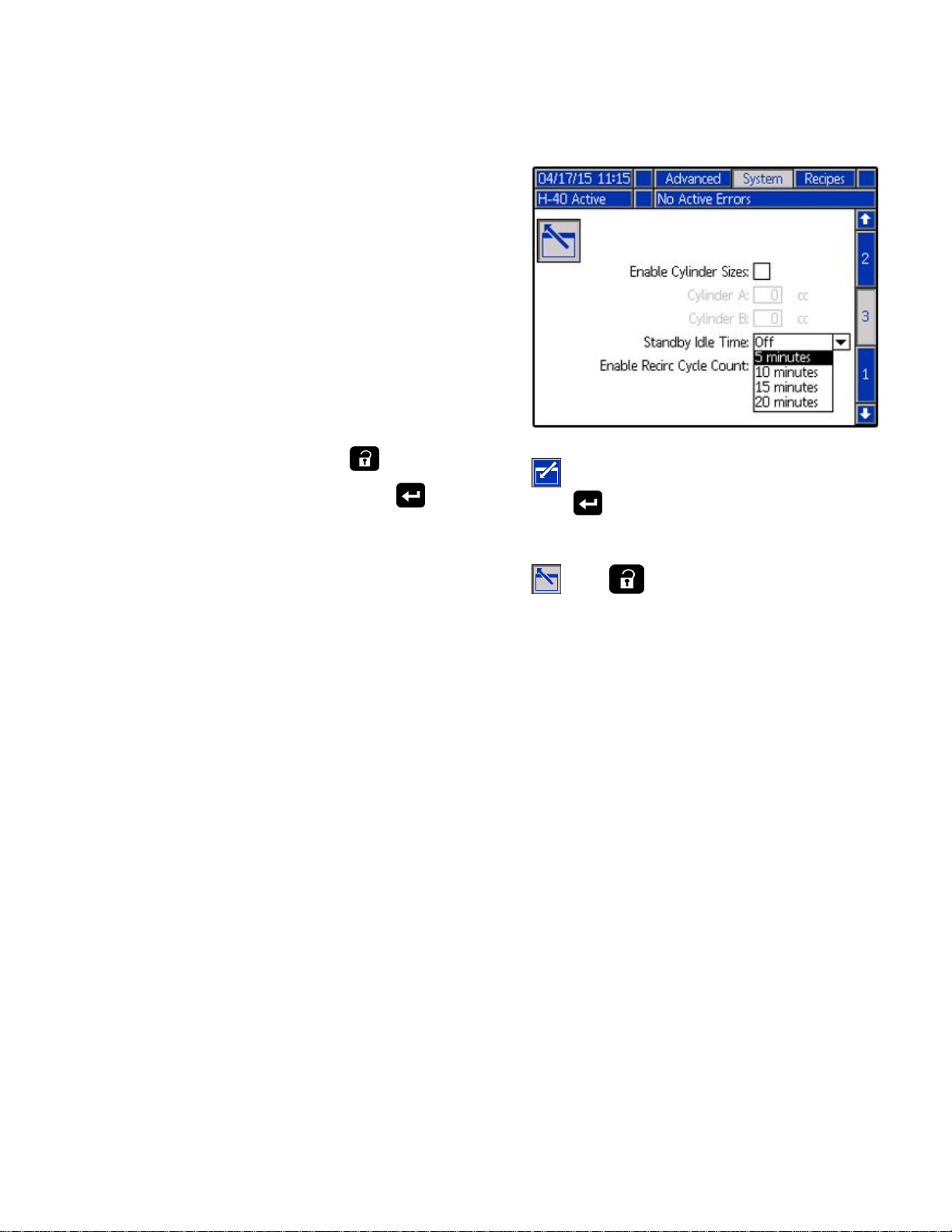
Standby
Standby Standby
Ifyoustopsprayingforaperiodoftime,theunitwill
enterstandbybyshuttingdowntheelectricmotor
andhydraulicpump,toreduceequipmentwearand
minimizeheatbuildup.ThepumpiconontheADM
Homescreenwillashwheninstandby.
NOTE:
NOTE: NOTE:
offduringstandby.
Torestart,sprayofftargetfortwoseconds.The
systemwillsensethepressuredropandthemotor
willrampuptofullspeedinafewseconds.
NOTE:
NOTE: NOTE:
Toactivateordeactivatestandby:
1.EntersetupmodebypressingontheADM.
2.GotoscreenSystem3andselectto
TheA,B,andHoseheatzoneswillnotshut
Thisfeatureisdisabledfromthefactory.
thepageforediting.
Standby
3.Selectthe“StandbyIdleTime”dropdownusing
andthearrowkeys.Selectthedesireddelay
enter
using
selectthedesiredvalue.
andthearrowkeys.Pressenterto
4.Exitthepageandreturntorunmodebypressing
,then.
334945B 53
Page 54

Shutdown
Shutdown
Shutdown Shutdown
NOTICE
NOTICE NOTICE
Propersystemsetup,startup,andshutdown
proceduresarecriticaltoelectricalequipment
reliability.Thefollowingproceduresensuresteady
voltage.Failuretofollowtheseprocedureswill
causevoltageuctuationsthatcandamage
electricalequipmentandvoidthewarranty.
1.Presstostopthepumps.
2.Turnoffallheatzones.
3.Relievepressure.See
PressureReliefProcedure,page55.
6.Turnofftheaircompressor,airdryer,and
breathingair.
7.TurnmainpowerswitchOFF.
Topreventelectricshockdonotremoveany
shroudsoropentheelectricalenclosuredoorwhile
thepowerisON.
8.Closealluidsupplyvalves.
4.PresstoparktheComponentAand
ComponentBpumps.Theparkoperationis
completewhengreendotgoesout.Verifythe
parkoperationiscompletebeforemovingtonext
step.
5.Presstodeactivatethesystem.
54 334945B
9.SetPRESSURERELIEF/SPRAYvalvesto
SPRAYtosealoutmoisturefromthedrainline.
10.Engagegunpistonsafetylockthencloseuid
inletvalvesAandB.
Fusion
Fusion Fusion
Probler
Probler Probler
Page 55

PressureReliefProcedure
SA
SB
GA
GB
Pressure
Pressure Pressure
FollowthePressureReliefProcedure
wheneveryouseethissymbol.
Thisequipmentstayspressurizeduntilpressure
ismanuallyrelieved.Tohelppreventserious
injuryfrompressurizeduid,suchasskininjection,
splashinguidandmovingparts,followthe
PressureReliefProcedurewhenyoustopspraying
andbeforecleaning,checking,orservicing
equipment.
The Fusion AP gun is shown.
Relief
Relief Relief
Procedure
Procedure Procedure
4.ClosegunuidinletvalvesAandB.
5.Shutofffeedpumpsandagitator,ifused.
6.Routeuidtowastecontainersorsupplytanks.
TurnPRESSURERELIEF/SPRAYvalves(SA,
SB)toPRESSURERELIEF/CIRCULATION
.Ensuregaugesdropto0.
1.Presstostopthepumps.
2.Turnoffallheatzones.
3.Relievepressureingunandperformgun
shutdownprocedure.Seegunmanual.
7.Engagegunpistonsafetylock.
8.Disconnectgunairlineandremovegunuid
manifold.
334945B 55
Page 56

Flushing
SA
SB
GA
GB
Flushing
Flushing Flushing
Toushentiresystem,circulatethroughgunuid
manifold(withmanifoldremovedfromgun).
Toavoidreandexplosion:
•Flushequipmentonlyinawell-ventilatedarea.
•Ensuremainpowerisoffandheateriscool
beforeushing.
•Donotturnonheateruntiluidlinesareclearof
solevent.
Toushfeedhoses,pumps,andheaters
separatelyfromheatedhoses,setPRESSURE
RELIEF/SPRAYvalves(SA,SB)toPRESSURE
RELIEF/CIRCULATION
lines(N).
.Flushthroughbleed
Topreventmoisturefromreactingwith
isocyanate,alwaysleavethesystemlled
withamoisture-freeplasticizeroroil.Donot
usewater.Neverleavethesystemdry.See
ImportantTwo-ComponentMaterialInformation.
56 334945B
Page 57

Maintenance
Maintenance
Maintenance Maintenance
Priortoperforminganymaintenanceprocedures,
followPressureReliefProcedure,page55.
Preventative
Preventative Preventative
Theoperatingconditionsofyourparticularsystem
determinehowoftenmaintenanceisrequired.
Establishapreventivemaintenancescheduleby
recordingwhenandwhatkindofmaintenanceis
needed,andthendeterminearegularschedulefor
checkingyoursystem.
•Inspecthydraulicanduidlinesforleaksdaily.
•Cleanupallhydraulicleaks;identifyandrepairthe
causeoftheleak.
•Inspectuidinletstrainerscreensdaily.Seebelow.
•KeepcomponentAfromexposuretomoistureto
preventcrystallization.
•Checkhydraulicuidlevelweekly.Check
hydraulicuidlevelonadipstick.Fluidlevel
mustbebetweenindentmarksondipstick.
Rellasrequiredwithapprovedhydraulicuid
(seeTechnicalSpecications,page66andthe
ApprovedAnti-Wear(AW)HydraulicOilstablein
theReactorRepair-Partsmanual334946.Ifuidis
darkincolor,changeuidandlter.
Maintenance
Maintenance Maintenance
Schedule
Schedule Schedule
Table
Table Table
Ambient
Ambient Ambient
Temperature
Temperature Temperature
0°to90°F
(-17°to32°C)
90°Fandabove
(32°Candabove)
Proportioner
Proportioner Proportioner
Fluid
Fluid Fluid
Inspectuidinletstrainerscreensdaily,see
FlushInletStrainerScreen,page58.
Grease
Grease Grease
Greasecirculationvalves(SAandSB)withFusion
grease(117773)weekly.
Frequency
6 66Frequency Frequency
Inlet
Strainer
Inlet Inlet
Strainer Strainer
Circulation
Circulation Circulation
Oil
Changes
of ofofOil Oil
Changes Changes
Recommended
Recommended Recommended
Frequency
Frequency Frequency
1000hoursor12months,
whichevercomesrst
500hoursor6months,
whichevercomesrst
Maintenance
Maintenance Maintenance
Screens
Screens Screens
Valves
Valves Valves
ISO
Lubricant
ISO ISO
Lubricant Lubricant
InspectISOlubricantlevelandcondition
daily.Rellorreplaceasneeded.See
PumpLubricationSystem,page59.
Moisture
Moisture Moisture
Topreventcrystallization,donotexposecomponent
Atomoistureinair.
Gun
Mix
Gun Gun
Mix Mix
•Changebreak-inoilinanewunitaftertherst250
hoursofoperationorwithin3months,whichever
comesrst.Seethetablebelowforrecommended
frequencyofoilchanges.
334945B 57
Cleangunmixchamberportsregularly.Seegun
manual.
Level
Level Level
Chamber
Chamber Chamber
Ports
Ports Ports
Page 58

Maintenance
Gun
Check
Gun Gun
Check Check
Cleanguncheckvalvescreensregularly.Seegun
manual.
Dust
Protection
Dust Dust
Protection Protection
Useclean,dry,oil-freecompressedairtoprevent
dustbuilduponcontrolmodules,fans,andmotor
(undershield).
Vent
Holes
Vent Vent
Holes Holes
Keepventholesonbottomandbackofelectrical
enclosureandsidesandbackoftransformer
enclosureopen..
Flush
Flush Flush
Theinletstrainerslteroutparticlesthatcanplugthe
pumpinletcheckvalves.Inspectthescreensdailyas
partofthestartuproutine,andcleanasrequired.
Valve
Valve Valve
Inlet
Inlet Inlet
Screens
Screens Screens
Strainer
Strainer Strainer
Screen
Screen Screen
1.Closetheuidinletvalveatthepumpinletand
shutofftheappropriatefeedpump.Thisprevents
materialfrombeingpumpedwhilecleaningthe
screen.
2.Placeacontainerunderthestrainerbasetocatch
drainoffwhenremovingthestrainerplug(C).
3.Removethescreen(A)fromthestrainer
manifold.Thoroughlyushthescreenwith
compatiblesolventandshakeitdry.Inspectthe
screen.Nomorethan25%ofthemeshshould
berestricted.Ifmorethan25%ofthemeshis
blocked,replacethescreen.Inspectthegasket
(B)andreplaceasrequired.
4.Ensurethepipeplug(D)isscrewedintothe
strainerplug(C).Installthestrainerplugwiththe
screen(A)ando-ring(B)inplaceandtighten.Do
notovertighten.Lettheo-ringmaketheseal.
5.Opentheuidinletvalve,ensurethatthereare
noleaks,andwipetheequipmentclean.Proceed
withoperation.
Isocyanatecancrystallizefrommoisture
contaminationorfromfreezing.Ifthechemicalsused
arecleanandproperstorage,transfer,andoperating
proceduresarefollowed,thereshouldbeminimal
contaminationoftheA-sidescreen.
Note
CleantheA-sidescreenonlyduring
dailystartup.Thisminimizesmoisture
contaminationbyimmediatelyushing
outanyisocyanateresidueatthestartof
dispensingoperations.
Figure10
58 334945B
Page 59

Maintenance
Pump
Pump Pump
ChecktheconditionoftheISOpumplubricantdaily.
Changethelubricantifitbecomesagel,itscolor
darkens,oritbecomesdilutedwithisocyanate.
Gelformationisduetomoistureabsorptionbythe
pumplubricant.Theintervalbetweenchanges
dependsontheenvironmentinwhichtheequipment
isoperating.Thepumplubricationsystemminimizes
exposuretomoisture,butsomecontaminationisstill
possible.
Lubricantdiscolorationisduetocontinualseepageof
smallamountsofisocyanatepastthepumppackings
duringoperation.Ifthepackingsareoperating
properly,lubricantreplacementduetodiscoloration
shouldnotbenecessarymoreoftenthanevery3or
4weeks.
Tochangepumplubricant:
1.FollowPressureReliefProcedure,page55.
2.Liftthelubricantreservoir(LR)outofthebracket
Lubrication
Lubrication Lubrication
(RB)andremovethecontainerfromthecap.
Holdingthecapoverasuitablecontainer,remove
thecheckvalveandallowthelubricanttodrain.
Reattachthecheckvalvetotheinlethose.
System
System System
5.Threadthereservoirontothecapassemblyand
placeitinthebracket.
6.Pushthelargerdiametersupply(ST)tube
approximately1/3ofthewayintothereservoir.
7.Pushthesmallerdiameterreturntube(RT)into
thereservoiruntilitreachesthebottom.
NOTE:
NOTE: NOTE:
thereservoirtoensurethatisocyanatecrystals
willsettletothebottomandnotbesiphonedinto
thesupplytubeandreturnedtothepump.
8.Thelubricationsystemisreadyforoperation.No
primingisrequired.
Thereturntubemustreachthebottomof
3.Drainthereservoirandushitwithclean
lubricant.
4.Whenthereservoirisushedclean,llwithfresh
lubricant.
PumpLubricationSystem
Figure11
334945B 59
Page 60

Errors
Errors
Errors Errors
View
View View
Whenanerroroccurstheerrorinformationscreen
displaystheactiveerrorcodeanddescription.
Theerrorcode,alarmbell,andactiveerrorswill
scrollinthestatusbar.Foralistofthetenmost
recenterrorsseeTroubleshooting.Errorcodesare
storedintheerrorloganddisplayedontheErrorand
TroubleshootingscreensontheADM.
Therearethreetypesoferrorsthatcanoccur.Errors
areindicatedonthedisplayaswellasbythelight
tower(optional).
Alarmsareindicatedby
aparametercriticaltotheprocesshasreacheda
levelrequiringthesystemtostop.Thealarmneeds
tobeaddressedimmediately.
Deviationsareindicatedby
indicatesaparametercriticaltotheprocesshas
reachedalevelrequiringattention,butnotsufcient
enoughtostopthesystematthistime.
Advisoriesareindicatedby
indicatesaparameterthatisnotimmediatelycritical
totheprocess.Theadvisoryneedsattentionto
preventmoreseriousissuesinthefuture.
Errors
Errors Errors
.Thisconditionindicates
.Thiscondition
.Thiscondition
Troubleshoot
Troubleshoot Troubleshoot
Totroubleshoottheerror:
1.Pressthesoftkeynextto“HelpWithThisError”
forhelpwiththeactiveerror.
Note
Press
previouslydisplayedscreen.
2.TheQRcodescreenwillbedisplayed.Scan
theQRcodewithyoursmartphonetobesent
directlytoonlinetroubleshootingfortheactive
errorcode.Otherwise,manuallynavigateto
http://help.graco.comandsearchfortheactive
error.
Errors
Errors Errors
ortoreturntothe
Todiagnosetheactiveerror,see
TroubleshootErrors,page60.
3.Ifnointernetconnectionisavailable,see
ErrorCodesandTroubleshooting,page61for
causesandsolutionsforeacherrorcode.
60 334945B
Page 61

ErrorCodesandTroubleshooting
Error
Error Error
Seesystemrepairmanual334946orvisithttp://help.graco.comforcausesandsolutionstoeacherrorcode,or
callyourGracocontactlistedonthebackpageofthismanual.
USB
USB USB
Download
Download Download
NOTE:
NOTE: NOTE:
languagelescanbemodiedifthelesareinthe
UPLOADfolderoftheUSBashdrive.SeeSystem
CongurationSettingsFile,CustomLanguageFile,
andUploadProceduresections.
1.InsertUSBashdriveintoUSBport.
2.ThemenubarandUSBindicatorlightsindicate
thattheUSBisdownloadingles.WaitforUSB
activitytocomplete.
3.RemoveUSBashdrivefromUSBport.
4.InsertUSBashdriveintoUSBportofcomputer.
5.TheUSBashdrivewindowautomaticallyopens.
Ifitdoesnot,openUSBashdrivefromwithin
Windows®Explorer.
6.OpenGRACOfolder.
7.Openthesystemfolder.Ifdownloadingdata
frommorethanonesystem,therewillbemore
thanonefolder.Eachfolderislabeledwiththe
correspondingserialnumberoftheADM(The
serialnumberisonthebackoftheADM.)
Codes
Codes Codes
Data
Data Data
Procedure
Procedure Procedure
Systemcongurationsettinglesandcustom
and
and and
Troubleshooting
Troubleshooting Troubleshooting
USB
USB USB
NOTE:
NOTE: NOTE:
AllocationTable)storagedevices.NTFS,usedby32
GBorgreaterstoragedevices,isnotsupported.
Duringoperation,theADMstoressystemand
performancerelatedinformationtomemoryinthe
formoflogles.TheADMmaintainssixlogles:
•EventLog
•JobLog
•DailyLog
•SystemSoftwareLog
•BlackboxLog
•DiagnosticsLog
FollowDownloadProcedure,page61,toretrieve
logles.
EachtimeaUSBashdriveisinsertedintotheADM
USBport,anewfoldernamedDATAxxxxiscreated.
Thenumberattheendofthefoldernameincreases
eachtimeaUSBashdriveisinsertedanddatais
downloadedoruploaded.
Event
Event Event
Logs
Logs Logs
TheADMcanread/writetoFAT(File
Log
Log Log
8.OpenDOWNLOADfolder.
9.OpenDATAxxxxfolderlabeledwiththehighest
number.Thehighestnumberindicatesthemost
recentdatadownload.
10.Openlogle.LoglesopeninMicrosoft®Excel
bydefaultaslongastheprogramisinstalled.
However,theycanalsobeopenedinanytext
editororMicrosoft®Word.
NOTE:
NOTE: NOTE:
(UTF-16)format.Ifopeningtheloglein
MicrosoftWord,selectUnicodeencoding.
334945B 61
AllUSBlogsaresavedinUnicode
Theeventloglenameis1–EVENT.CSVandis
storedintheDATAxxxxfolder.
Theeventlogmaintainsarecordofthelast49,000
eventsanderrors.Eacheventrecordcontains:
•Dateofeventcode
•Timeofeventcode
•Eventcode
•Eventtype
•Actiontaken
•EventDescription
Eventcodesincludebotherrorcodes(alarms,
deviations,andadvisories)andrecordonlyevents.
ActionsTakenincludessettingandclearingevent
conditionsbythesystem,andacknowledgingerror
conditionsbytheuser.
Page 62

ErrorCodesandTroubleshooting
Job
Log
Job Job
Log Log
Thefollowingdataisstoredinthisle:
Thejobloglenameis2–JOB.CSVandisstored
intheDATAxxxxfolder.
Thejoblogmaintainsarecordofdatapoints
basedontheUSBLogFrequencydened
intheSetupscreens.TheADMstoresthe
last237,000datapointsfordownload.See
Setup-AdvancedScreen3—USB,page35,for
informationonsettingtheDownloadDepthandUSB
LogFrequency.
•Datapointdate
•Datapointtime
•Asidetemperature
•Bsidetemperature
•Hosetemperature
•Asidetemperaturesetpoint
•Bsidetemperaturesetpoint
•Hosetemperaturesetpoint
•PressureA
•PressureB
•Asideinletpressure(Eliteonly)
•Bsideinletpressure(Eliteonly)
•Datethatmaterialwassprayed
•Time—unusedcolumn
•Totalpumpcyclecountforday
•Totalvolumesprayedforday
System
System System
Thesystemsoftwarelenameis4–SYSTEM.CSV
andisstoredintheDATAxxxxfolder.
Thesystemsoftwarelogliststhefollowing:
•Datelogwascreated
•Timelogwascreated
•Componentname
•Softwareversionloadedontheabovecomponent
Blackbox
Blackbox Blackbox
Theblackboxlenameis5–BLACKB.CSVandis
storedintheDATAxxxxfolder.
TheBlackboxlogmaintainsarecordofhowthe
systemrunsandthefeaturesthatareused.Thislog
willhelpGracotroubleshootsystemerrors.
Diagnostics
Diagnostics Diagnostics
Software
Software Software
Log
Log Log
Log
Log Log
File
File File
Log
File
Log Log
File File
•Asideinlettemperature(Eliteonly)
•Bsideinlettemperature(Eliteonly)
•Inletpressuresetpoint
•Systemlifetimepumpcyclecounts
•UsageVolume(manual)
•Pressure,volume,andtemperatureunits
•Jobname/number
Daily
Daily Daily
Thedailyloglenameis3–DAILY.CSVandisstored
intheDATAxxxxfolder.
Thedailylogmaintainsarecordofthetotalcycle
andvolumesprayedonanydaythatthesystemis
poweredup.Thevolumeunitswillbethesameunits
thatwereusedintheJobLog.
Log
Log Log
Thediagnosticslenameis6–DIAGNO.CSVandis
storedintheDATAxxxxfolder.
TheDiagnosticslogmaintainsarecordofhowthe
systemrunsandthefeaturesthatareused.Thislog
willhelpGracotroubleshootsystemerrors.
System
System System
Thesystemcongurationsettingslenameis
SETTINGS.TXTandisstoredintheDOWNLOAD
folder.
Asystemcongurationsettingsleautomatically
downloadseachtimeaUSBashdriveisinserted
intotheADM.Usethisletobackupsystem
settingsforfuturerecoveryortoeasilyreplicate
settingsacrossmultiplesystems.Refertothe
UploadProcedure,page63forinstructionsonhow
tousethisle.
Conguration
Conguration Conguration
Settings
Settings Settings
62 334945B
Page 63

ErrorCodesandTroubleshooting
Custom
Custom Custom
ThecustomlanguagelenameisDISPTEXT.TXT
andisstoredintheDOWNLOADfolder.
Acustomlanguageleautomaticallydownloads
eachtimeaUSBashdriveisinsertedintotheADM.
Ifdesired,usethisletocreateauser-denedsetof
customlanguagestringstobedisplayedwithinthe
ADM.
ThesystemisabletodisplaythefollowingUnicode
characters.Forcharactersoutsideofthisset,
thesystemwilldisplaytheUnicodereplacement
character,whichappearsasawhitequestionmark
insideofablackdiamond.
•U+0020-U+007E(BasicLatin)
•U+00A1-U+00FF(Latin-1Supplement)
•U+0100-U+017F(LatinExtended-A)
•U+0386-U+03CE(Greek)
•U+0400-U+045F(Cyrillic)
Create
Create Create
Thecustomlanguageleisatab-delimitedtextle
thatcontainstwocolumns.Therstcolumnconsists
ofalistofstringsinthelanguageselectedatthe
timeofdownload.Thesecondcolumncanbeused
toenterthecustomlanguagestrings.Ifacustom
languagewaspreviouslyinstalled,thiscolumn
containsthecustomstrings.Otherwisethesecond
columnisblank.
Modifythesecondcolumnofthecustomlanguagele
asneededandthefollowUploadProcedure,page63,
toinstallthele.
Theformatofthecustomlanguageleiscritical.
Thefollowingrulesmustbefollowedinorderforthe
installationprocesstosucceed.
•Deneacustomstringforeachrowinthesecond
column.
NOTE:
NOTE: NOTE:
mustdeneacustomstringforeachentryinthe
DISPTEXT.TXTle.Blanksecond-columnelds
willbedisplayedblankontheADM.
•ThelenamemustbeDISPTEXT.TXT.
Language
Language Language
Custom
Custom Custom
Ifthecustomlanguageleisused,you
Language
Language Language
File
File File
Strings
Strings Strings
•Theleformatmustbeatab-delimitedtextle
usingUnicode(UTF-16)characterrepresentation.
•Thelemustcontainonlytwocolumns,with
columnsseparatedbyasingletabcharacter.
•Donotaddorremoverowsfromthele.
•Donotchangetheorderoftherows.
Upload
Upload Upload
Usethisproceduretoinstallasystemconguration
leand/oracustomlanguagele.
1.Ifnecessary,followtheDownload Download
automaticallygeneratetheproperfolderstructure
ontheUSBashdrive.
2.InsertUSBashdriveintoUSBportofcomputer.
3.TheUSBashdrivewindowautomaticallyopens.
Ifitdoesnot,openUSBashdrivefromwithin
WindowsExplorer.
4.OpenGRACOfolder.
5.Openthesystemfolder.Ifworkingwithmore
thanonesystem,therewillbemorethanone
folderwithintheGRACOfolder.Eachfolderis
labeledwiththecorrespondingserialnumberof
theADM.(Theserialnumberisonthebackof
theADM.)
6.Ifinstallingthesystemcongurationsettings
le,placeSETTINGS.TXTleintotheUPLOAD
folder.
7.Ifinstallingthecustomlanguagele,place
DISPTEXT.TXTleintotheUPLOADfolder.
8.RemoveUSBashdrivefromthecomputer.
9.InstallUSBashdriveintotheADMUSBport.
10.ThemenubarandUSBindicatorlightsindicate
thattheUSBisdownloadingles.WaitforUSB
activitytocomplete.
11.RemoveUSBashdrivefromUSBport.
NOTE:
NOTE: NOTE:
userscannowselectthenewlanguage
fromtheLanguagedrop-downmenuin
AdvancedScreen1—General,page35.
Procedure
Procedure Procedure
Download
Ifthecustomlanguagelewasinstalled,
Procedure
Procedure Procedure
to
334945B 63
Page 64

PerformanceCharts
2000
(13.8, 138)
1500
(10.3, 103)
1000
(6.9, 69)
500
(3.4, 34)
0 15
(6.8)25(11.4)35(15.9)
5
(2.3)
55
(25.0)
45
(20.5)
A
B
C
E
D
F
ti26328a
Performance
Performance Performance
Usethischarttohelpidentifytheproportionerthatwillworkmostefcientlywitheachmixchamber.Flowrates
arebasedonamaterialviscosityof60cps.
Topreventsystemdamage,donotpressurizethe
systemabovethelinefortheguntipsizebeingused.
Foam
Foam Foam
Table
Table Table
PRESSUREpsi
(MPa,bar)
Performance
Performance Performance
Foam
7 77Foam Foam
Performance
Performance Performance
Charts
Charts Charts
NOTICE
NOTICE NOTICE
Chart
Chart Chart
Chart
Chart Chart
KEY
KEY KEY
A=H-30at50Hz
B=H30at60Hz
C=H-40at50Hz
D=H-40at60Hz
E=H-50at50Hz
F=H-50at60Hz
FLOWrateinlb/min(kg/min)
64 334945B
Page 65
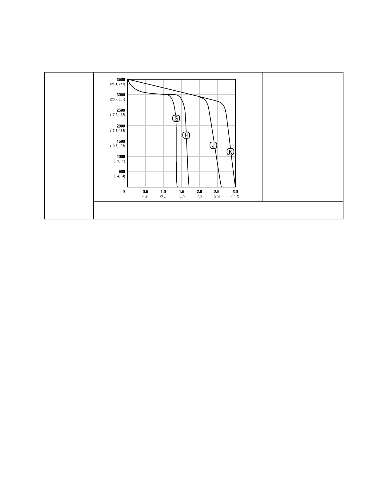
PerformanceCharts
2000
(13.8, 138)
2500
(17.2, 172)
3000
(20.7, 207)
3500
(24.1, 241)
1500
(10.3, 103)
0 1.0
(3.8)
1.5
(5.7)
2.0
(7.6)
0.5
(1.9)
3.0
(11.4)
2.5
(9.5)
ti26345a
G
H
J
K
1000
(6.9, 69)
500
(3.4, 34)
Coatings
Coatings Coatings
Table
Table Table
8 88Coatings Coatings
PRESSUREpsi
(MPa,bar)
Performance
Performance Performance
Coatings
Performance
Performance Performance
Chart
Chart Chart
Chart
Chart Chart
KEY
KEY KEY
G=H-XP2at50Hz
H=H-XP2at60Hz
J=H-XP3at50Hz
K=H-XP3at60Hz
FLOWrateinlb/min(kg/min)
334945B 65
Page 66

TechnicalSpecications
Technical
Technical Technical
Reactor
Reactor Reactor
Maximum
Maximum Maximum
ModelsH-30,H-40,andH-502000psi13.8MPa,138bar
ModelsH-XP2andH-XP33500psi24.1MPa,241bar
Fluid:
Fluid: Fluid:
ModelH-401.91:1
ModelsH-30andH-501.64:1
ModelsH-XP2andH-XP32.79:1
Fluid
Fluid Fluid
ComponentA(ISO)3/4npt(f),250psimaximum3/4npt(f),1.75MPa,17.5
ComponentB(RES)3/4npt(f),250psimaximum3/4npt(f),1.75MPa,17.5
Fluid
Fluid Fluid
ComponentA(ISO)#81/2in.JIC,with#55/16in.JICadapter
Hydraulic
2 22Hydraulic Hydraulic
Fluid
Fluid Fluid
Oil
Pressure
Oil Oil
Pressure Pressure
Inlets
Inlets Inlets
Outlets
Outlets Outlets
Specications
Specications Specications
Proportioning
Proportioning Proportioning
Working
Working Working
Pressure
Pressure Pressure
Ratio
Ratio Ratio
System
System System
U.S.
U.S. U.S.
for
Bare
for for
Proportioners
Bare Bare
Proportioners Proportioners
Metric
Metric Metric
barmaximum
barmaximum
ComponentB(RES)#105/8in.JIC,with#63/8in.JICadapter
Fluid
Circulation
Fluid Fluid
Circulation Circulation
1/4npsm(m)
Maximum
Maximum Maximum
Maximum
Maximum Maximum
ModelH-30
ModelH-XP2
ModelH-50
ModelH-40
ModelH-XP3
Output
Output Output
ModelH-400.063gal.0.23liter
ModelsH-30andH-500.073gal.0.28liter
ModelsH-XP2andH-XP30.042gal.0.16liter
Per
Per Per
Ports
Ports Ports
250psi1.75MPa,17.5bar
Fluid
Temperature
Fluid Fluid
Temperature Temperature
190°F88°C
Output
Output Output
(10
weight
(10 (10
weight weight
Cycle
(A
Cycle Cycle
and
(A (A
and and
oil
ambient
oil oil
at atatambient ambient
B)
B) B)
temperature)
temperature) temperature)
28lb/min(60Hz)13kg/min(60Hz)
1.5gpm(60Hz)5.7liter/min(60Hz)
52lb/min(60Hz)24kg/min(60Hz)
45lb/min(60Hz)20kg/min(60Hz)
2.8gpm(60Hz)10.6liter/min(60Hz)
66 334945B
Page 67

Line
Voltage
Line Line
Voltage Voltage
Amperage
Amperage Amperage
SeetheModelslistinginthemanual.
Heater
Heater Heater
SeetheModelslistinginthemanual.
Hydraulic
Hydraulic Hydraulic
Recommended
Recommended Recommended
Sound
Sound Sound
Sound
Sound Sound
Weight
Weight Weight
Options
Options Options
Requirement
Requirement Requirement
Power
Power Power
Power,
Power, Power,
Pressure
Pressure Pressure
(A
and
(A (A
and and
Reservoir
Reservoir Reservoir
Hydraulic
Hydraulic Hydraulic
per
ISO
per per
ISO ISO
1 11m mmFrom From
TechnicalSpecications
230V1phaseand230V3phaseunits:195–264Vac,50/60Hz
400V3phaseunits:338–457Vac,50/60Hz
(phase)
(phase) (phase)
heaters
B BBheaters heaters
Capacity
Capacity Capacity
9614–2
9614–2 9614–2
From
total)
total) total)
3.5gal.13.6liters
Fluid
Fluid Fluid
Citgo,A/WHydraulicOil,ISOGrade46
90.2dB(A)
Equipment
Equipment Equipment
82.6dB(A)
H-40,H-50,H-XP3,600lb272kg
H-30,10kW544lb247kg
H-30,H-XP2,15kW556lb252kg
Wetted
Wetted Wetted
Parts
Parts Parts
Aluminum,stainlesssteel,zinc-platedcarbonsteel,brass,carbide,
chrome,uoroelastomer,PTFE,ultra-highmolecularweight
polyethylene,chemicallyresistanto-rings
All other brand names or marks are used for identication purposes and are trademarks of their respective
owners.
334945B 67
Page 68

Notes
Notes
Notes Notes
68 334945B
Page 69

Dimensions
Dimensions
Dimensions Dimensions
334945B 69
Page 70

Graco
Graco Graco
Extended
Extended Extended
Warranty
Warranty Warranty
GracowarrantsallequipmentreferencedinthisdocumentwhichismanufacturedbyGracoandbearingits
nametobefreefromdefectsinmaterialandworkmanshiponthedateofsaletotheoriginalpurchaserforuse.
Gracowill,foraperiodasdenedinthetablebelowfromthedateofsale,repairorreplaceanypartofthe
equipmentdeterminedbyGracotobedefective.Thiswarrantyappliesonlywhentheequipmentisinstalled,
operatedandmaintainedinaccordancewithGraco’swrittenrecommendations.
Description
Part
Part Part
24U854
24Y263
24U855
Description Description
AdvancedDisplayModule
HydraulicControlModule36Monthsor2MillionCycles(whichevercomesrst)
TemperatureControl
Module
AllOtherParts
Warranty
Warranty Warranty
36Monthsor2MillionCycles(whichevercomesrst)
36Monthsor2MillionCycles(whichevercomesrst)
12Months
Period
Period Period
Thiswarrantydoesnotcover,andGracoshallnotbeliableforgeneralwearandtear,oranymalfunction,
damageorwearcausedbyfaultyinstallation,misapplication,abrasion,corrosion,inadequateorimproper
maintenance,negligence,accident,tampering,orsubstitutionofnon-Gracocomponentparts.NorshallGraco
beliableformalfunction,damageorwearcausedbytheincompatibilityofGracoequipmentwithstructures,
accessories,equipmentormaterialsnotsuppliedbyGraco,ortheimproperdesign,manufacture,installation,
operationormaintenanceofstructures,accessories,equipmentormaterialsnotsuppliedbyGraco.
Thiswarrantyisconditionedupontheprepaidreturnoftheequipmentclaimedtobedefectivetoanauthorized
Gracodistributorforvericationoftheclaimeddefect.Iftheclaimeddefectisveried,Gracowillrepairorreplace
freeofchargeanydefectiveparts.Theequipmentwillbereturnedtotheoriginalpurchasertransportation
prepaid.Ifinspectionoftheequipmentdoesnotdiscloseanydefectinmaterialorworkmanship,repairswillbe
madeatareasonablecharge,whichchargesmayincludethecostsofparts,labor,andtransportation.
THIS
WARRANTY
THIS THIS
WARRANTY WARRANTY
INCLUDING
INCLUDING INCLUDING
FOR
FOR FOR
PARTICULAR
A AAPARTICULAR PARTICULAR
IS
EXCLUSIVE,
IS IS
BUT
BUT BUT
EXCLUSIVE, EXCLUSIVE,
NOT
LIMITED
NOT NOT
LIMITED LIMITED
PURPOSE
PURPOSE PURPOSE
AND
IS
IN
LIEU
OF
ANY
AND AND
IS IS
IN IN
LIEU LIEU
TO
WARRANTY
TO TO
WARRANTY WARRANTY
OF OF
OF
MERCHANTABILITY
OF OF
MERCHANTABILITY MERCHANTABILITY
OTHER
ANY ANY
OTHER OTHER
WARRANTIES,
WARRANTIES, WARRANTIES,
OR
OR OR
EXPRESS
EXPRESS EXPRESS
WARRANTY
WARRANTY WARRANTY
OR
IMPLIED,
OR OR
OF
OF OF
IMPLIED, IMPLIED,
FITNESS
FITNESS FITNESS
.
Graco’ssoleobligationandbuyer’ssoleremedyforanybreachofwarrantyshallbeassetforthabove.The
buyeragreesthatnootherremedy(including,butnotlimitedto,incidentalorconsequentialdamagesforlost
prots,lostsales,injurytopersonorproperty,oranyotherincidentalorconsequentialloss)shallbeavailable.
Anyactionforbreachofwarrantymustbebroughtwithintwo(2)yearsofthedateofsale.
GRACO
GRACO GRACO
AND
AND AND
MATERIALS
MATERIALS MATERIALS
MAKES
MAKES MAKES
FITNESS
FITNESS FITNESS
NO
WARRANTY,
NO NO
WARRANTY, WARRANTY,
FOR
FOR FOR
OR
OR OR
PARTICULAR
A AAPARTICULAR PARTICULAR
COMPONENTS
COMPONENTS COMPONENTS
AND
DISCLAIMS
AND AND
DISCLAIMS DISCLAIMS
PURPOSE,
PURPOSE, PURPOSE,
SOLD
BUT
SOLD SOLD
NOT
BUT BUT
NOT NOT
ALL
IMPLIED
ALL ALL
IN
IN IN
IMPLIED IMPLIED
CONNECTION
CONNECTION CONNECTION
MANUFACTURED
MANUFACTURED MANUFACTURED
WARRANTIES
WARRANTIES WARRANTIES
WITH
ACCESSORIES,
WITH WITH
ACCESSORIES, ACCESSORIES,
BY
GRACO
BY BY
GRACO GRACO
OF
MERCHANTABILITY
OF OF
MERCHANTABILITY MERCHANTABILITY
EQUIPMENT,
EQUIPMENT, EQUIPMENT,
.
Theseitemssold,butnotmanufacturedbyGraco(suchaselectricmotors,switches,hose,etc.),aresubjectto
thewarranty,ifany,oftheirmanufacturer.Gracowillprovidepurchaserwithreasonableassistanceinmaking
anyclaimforbreachofthesewarranties.
InnoeventwillGracobeliableforindirect,incidental,specialorconsequentialdamagesresultingfromGraco
supplyingequipmenthereunder,orthefurnishing,performance,oruseofanyproductsorothergoodssold
hereto,whetherduetoabreachofcontract,breachofwarranty,thenegligenceofGraco,orotherwise.
FOR
GRACO
FOR FOR
GRACO GRACO
CANADA
CANADA CANADA
CUSTOMERS
CUSTOMERS CUSTOMERS
ThePartiesacknowledgethattheyhaverequiredthatthepresentdocument,aswellasalldocuments,notices
andlegalproceedingsenteredinto,givenorinstitutedpursuantheretoorrelatingdirectlyorindirectlyhereto,be
drawnupinEnglish.Lespartiesreconnaissentavoirconvenuquelarédactionduprésentedocumentseraen
Anglais,ainsiquetousdocuments,avisetprocéduresjudiciairesexécutés,donnésouintentés,àlasuitedeou
enrapport,directementouindirectement,aveclesprocéduresconcernées.
Graco
Graco Graco
Information
Information Information
ForthelatestinformationaboutGracoproducts,visitwww.graco.com.
Forpatentinformation,seewww.graco.com/patents.
To
place
an
To To
place place
Phone:
Phone: Phone:
Allwrittenandvisualdatacontainedinthisdocumentreectsthelatestproductinformationavailableatthetimeofpublication.
order,
an an
order, order,
contactyourGracoDistributororcalltoidentifythenearestdistributor.
612-623-6921or ororToll Toll
GRACO
GRACO GRACO
Copyright
Copyright Copyright
Toll
Free:
Free: Free:
1-800-328-0211Fax: Fax:
Gracoreservestherighttomakechangesatanytimewithoutnotice.
OriginalInstructions.ThismanualcontainsEnglish.MM334945 334945
International
INC.
INC. INC.
2014,
2014, 2014,
International International
AND
SUBSIDIARIES
AND AND
SUBSIDIARIES SUBSIDIARIES
Graco
Graco Graco
Graco
Graco Graco
Ofces:
Ofces: Ofces:
Inc.
All
Inc. Inc.
Graco
All All
Graco Graco
Fax:
Headquarters:
Headquarters: Headquarters:
Belgium,China,Japan,Korea
P.O.
BOX
• ••P.O. P.O.
BOX BOX
manufacturing
manufacturing manufacturing
www.graco.com
RevisionB,May2015
612-378-3505
Minneapolis
1441
MINNEAPOLIS
1441 1441
• ••MINNEAPOLIS MINNEAPOLIS
locations
locations locations
334945
MN
55440-1441
MN MN
are
are are
55440-1441 55440-1441
registered
registered registered
USA
• ••USA USA
ISO
9001.
to totoISO ISO
9001. 9001.
 Loading...