

Page 1
Operation,Repair,andParts
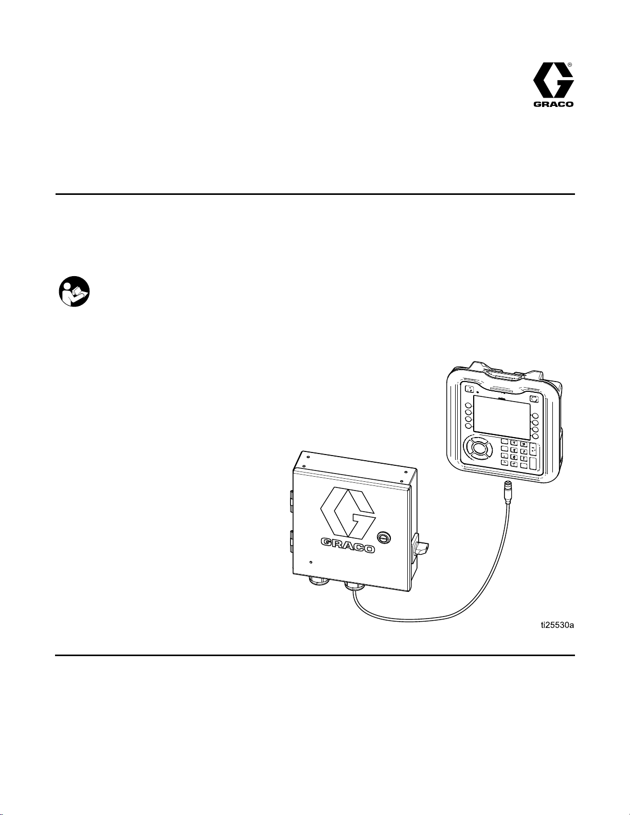
InvisiPac®
InvisiPac® InvisiPac®
To
control
To To
control control
Not
approved
Not Not
approved approved
See page 3 for model information and
Agency approvals.
uid
dispense
uid uid
dispense dispense
for
use
for for
use use
ImportantSafetyInstructions.Readallwarningsandinstructionsin
thismanualandrelatedmanuals.Savetheseinstructions.
Pattern
Pattern Pattern
valves
valves valves
explosive
in ininexplosive explosive
Controller
Controller Controller
334784A
EN
of
adhesive
of of
adhesive adhesive
atmospheres
atmospheres atmospheres
supply
supply supply
equipment.
equipment. equipment.
or
hazardous
or or
hazardous hazardous
For
professional
For For
professional professional
locations.
locations. locations.
use
only.
use use
only. only.
PROVENQUALITY.LEADINGTECHNOLOGY.
Page 2

Contents
Contents Contents
Models...............................................................3
AgencyApprovals...............................................3
RelatedManuals................................................3
Warnings...........................................................4
Overview............................................................7
ComponentIdentication.....................................8
Installation..........................................................9
Mounting.....................................................9
KeyToken...................................................9
ConnectAdvancedDisplayModule
(ADM)............................................9
ValveInstallation..........................................10
TriggerInstallation.......................................10
PLCInputsandOutputsInstallation
(optional)........................................11
EncoderInstallation(PC-8eonly)..................12
RunUpInstallation(PC-8eonly)...................12
ConnectElectricalCord................................13
Screens.............................................................14
ScreenMaps...............................................14
HMIInterface...............................................15
PCScreens.................................................16
AdvancedScreens.......................................27
Stitching.............................................................29
Denitions...................................................29
Setup..........................................................29
LineSpeed.........................................................30
RunUpControl...................................................31
RunUpSetup..............................................31
HighCalibrationPoint...................................31
LowCalibrationPoint...................................31
UserSettingEntry........................................31
UserSettings...............................................31
RandomLengthBeadMode.........................32
MirrorMode.................................................33
Calibration..........................................................34
GunCompensation(optional).......................34
Verication.........................................................35
Valves.........................................................35
Triggers.......................................................35
Encoder......................................................35
RunUpControl............................................35
PLCInputs..................................................35
Troubleshooting..................................................36
ErrorCodes.................................................36
Display........................................................37
Pattern........................................................37
Valve..........................................................38
Trigger........................................................38
Encoder......................................................38
RunUp........................................................39
PLCInputsandOutputs...............................39
SoftwareUpdateProcedure................................40
USBDownload...................................................41
DownloadProcedure....................................41
AccessingFiles............................................41
USBLogs....................................................41
Parts..................................................................42
Kits.............................................................44
WiringDiagram...................................................45
TechnicalData...................................................46
Notes.................................................................47
GracoStandardWarranty....................................48
2
334784A
Page 3
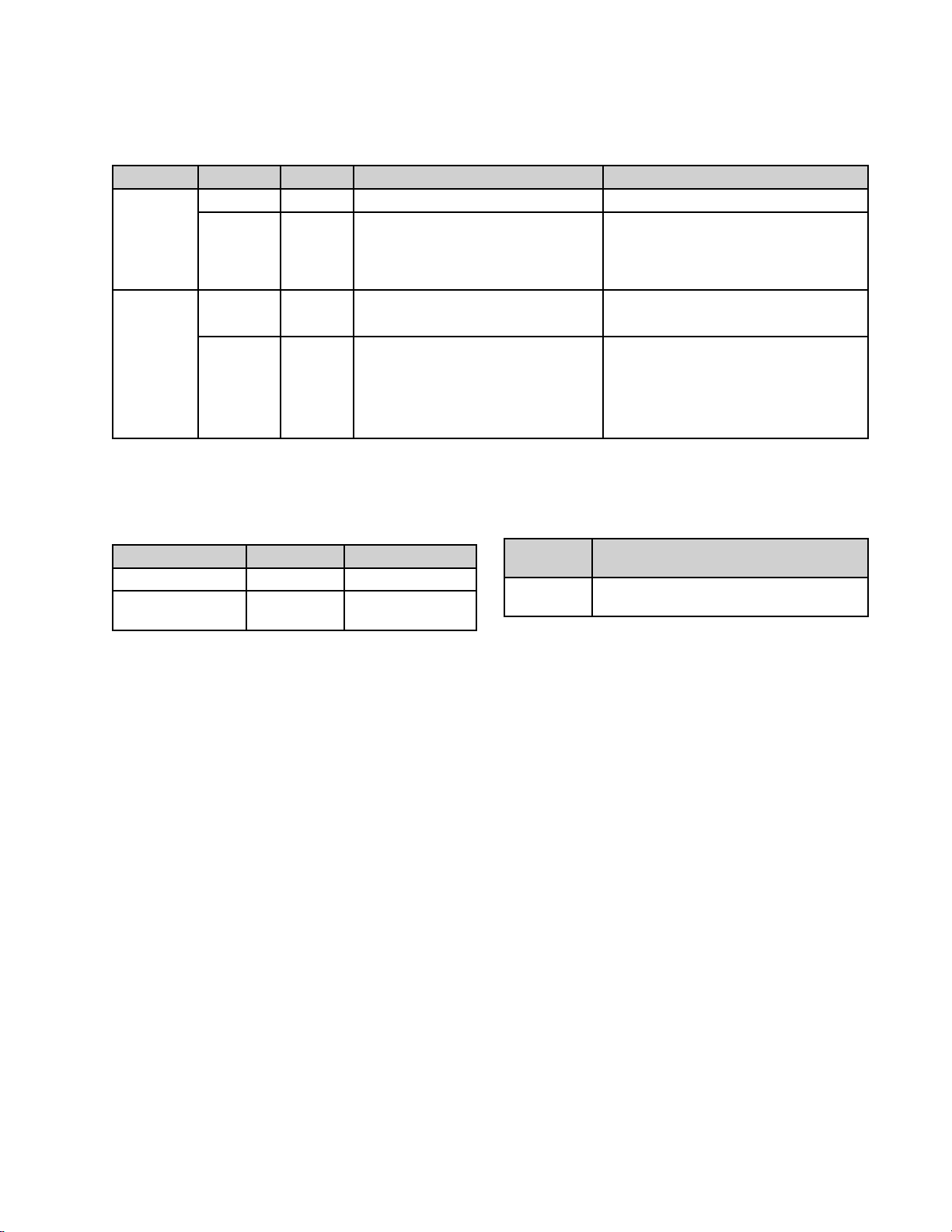
Models
Models
Models Models
Usage
Usage Usage
With
InvisiPac
Without
InvisiPac
Agency
Agency Agency
Type
Type Type
PatternController
AdvancedDisplay
Module
Part
Part Part
24X523
24X524
24X525
24X526
Approvals
Approvals Approvals
Type
Type Type
PC-8
PC-8e
PC-8
PC-8e
Description
Description Description
127971
24E451
Description
Description Description
Timeordistancemode,noencoder
Timeordistancemode,withor
withoutencoder
Runupcontrol(optional)24X626—KeyTokenforEncoder
Timeordistancemode,noencoder
Timeordistancemode,withor
withoutencoder
Runupcontrol(optional)
Related
Related Related
Manual
Contents
Contents Contents
CE,ETL,cETL
CE,ETL,cETL
Manual Manual
Number
Number Number
333347InvisiPacHM25andHM50Tank-Free™
Contents
Contents Contents
127971—PatternController
127971—PatternController
andRunup
127971—PatternController
24P860—AdvancedDisplayModule
127971—PatternController
24P860—AdvancedDisplayModule
24X626—KeyTokenforEncoder
andRunup
Manuals
Manuals Manuals
Product
Product Product
HotMeltDeliverySystem
334784A 3
Page 4
Warnings
Warnings
Warnings Warnings
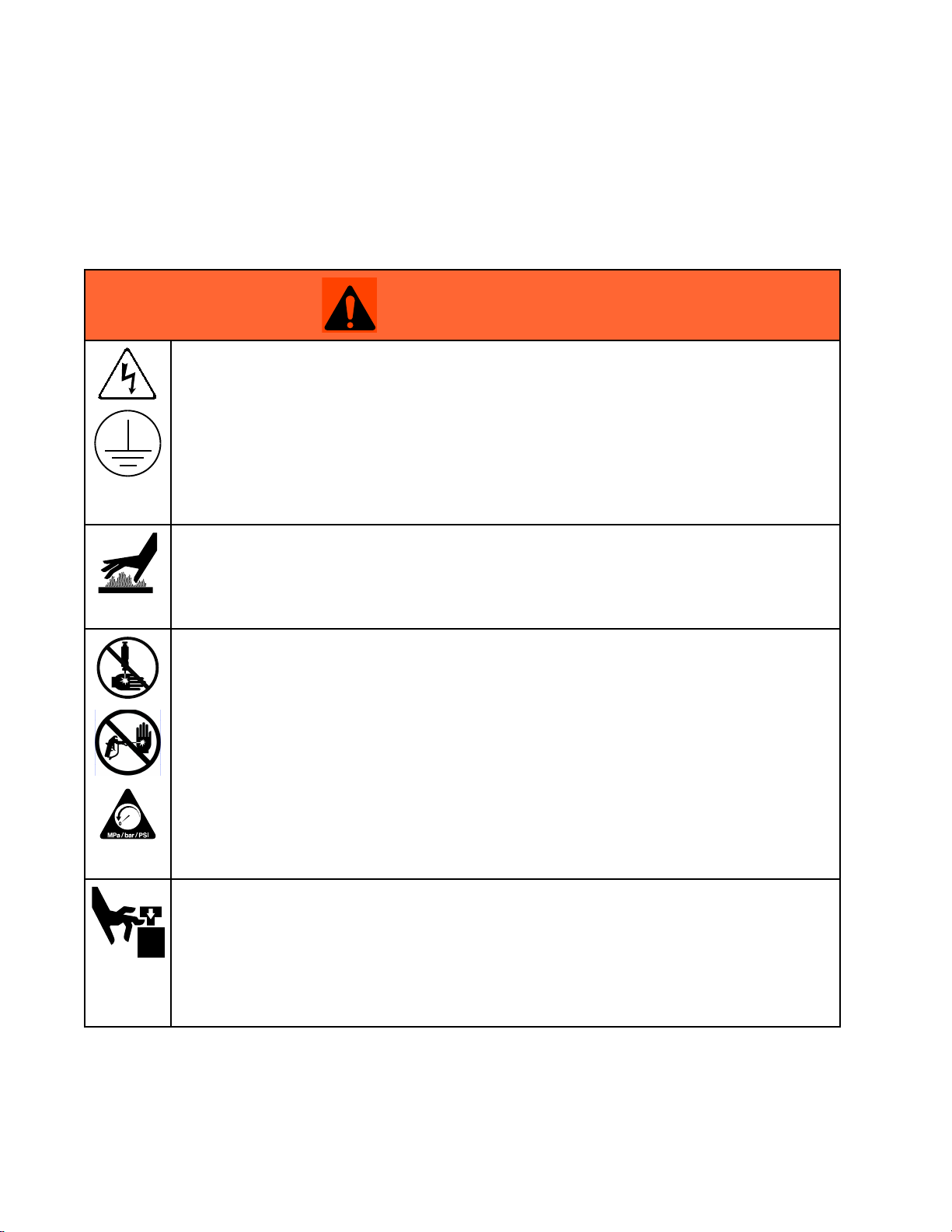
Thefollowingwarningsareforthesetup,use,grounding,maintenance,andrepairofthisequipment.The
exclamationpointsymbolalertsyoutoageneralwarningandthehazardsymbolsrefertoprocedure-specic
risks.Whenthesesymbolsappearinthebodyofthismanualoronwarninglabels,referbacktothese
Warnings.Product-specichazardsymbolsandwarningsnotcoveredinthissectionmayappearthroughout
thebodyofthismanualwhereapplicable.
WARNING
WARNING WARNING
ELECTRIC
ELECTRIC ELECTRIC
Thisequipmentmustbegrounded.Impropergrounding,setup,orusageofthesystemcan
causeelectricshock.
•Turnoffanddisconnectpoweratmainswitchbeforedisconnectinganycablesandbefore
servicingorinstallingequipment.
•Connectonlytogroundedpowersource.
•Allelectricalwiringmustbedonebyaqualiedelectricianandcomplywithalllocalcodes
andregulations.
BURN
BURN BURN
SHOCK
SHOCK SHOCK
HAZARD
HAZARD HAZARD
HAZARD
HAZARD HAZARD
Equipmentsurfacesanduidthatisheatedcanbecomeveryhotduringoperation.Toavoid
severeburns:
•Donottouchhotuidorequipment.
SKIN
INJECTION
SKIN SKIN
INJECTION INJECTION
High-pressureuidfromdispensingdevice,hoseleaks,orrupturedcomponentswillpierce
skin.Thismaylooklikejustacut,butitisaseriousinjurythatcanresultinamputation.Get Get
immediate
immediate immediate
•Donotpointdispensingdeviceatanyoneoratanypartofthebody.
•Donotputyourhandovertheuidoutlet.
•Donotstopordeectleakswithyourhand,body,glove,orrag.
•FollowthePressure Pressure
checking,orservicingequipment.
•Tightenalluidconnectionsbeforeoperatingtheequipment.
•Checkhosesandcouplingsdaily.Replacewornordamagedpartsimmediately.
MOVING
MOVING MOVING
Movingpartscanpinch,cutoramputatengersandotherbodyparts.
•Keepclearofmovingparts.
•Donotoperateequipmentwithprotectiveguardsorcoversremoved.
•Pressurizedequipmentcanstartwithoutwarning.Beforechecking,moving,orservicing
equipment,followthePressure Pressure
surgical
surgical surgical
PARTS
PARTS PARTS
HAZARD
HAZARD HAZARD
treatment.
treatment. treatment.
Pressure
Relief
Procedure
Relief Relief
Procedure Procedure
HAZARD
HAZARD HAZARD
Pressure
Relief
Relief Relief
whenyoustopdispensingandbeforecleaning,
Procedure
Procedure Procedure
anddisconnectallpowersources.
Get
4
334784A
Page 5
Warnings
WARNING
WARNING WARNING
EQUIPMENT
EQUIPMENT EQUIPMENT
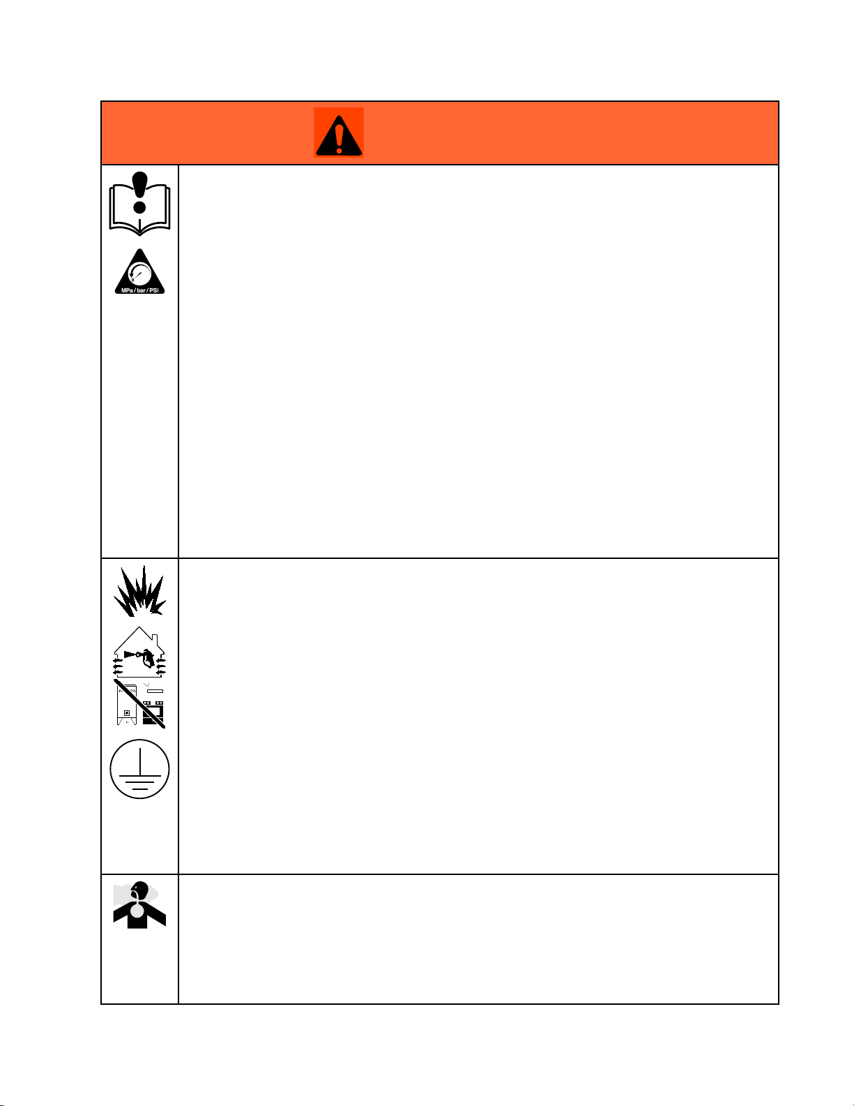
Misusecancausedeathorseriousinjury.
•Donotoperatetheunitwhenfatiguedorundertheinuenceofdrugsoralcohol.
•Donotexceedthemaximumworkingpressureortemperatureratingofthelowestrated
systemcomponent.SeeTechnical Technical
•Useuidsandsolventsthatarecompatiblewithequipmentwettedparts.SeeTechnicalData
inallequipmentmanuals.Readuidandsolventmanufacturer’swarnings.Forcomplete
informationaboutyourmaterial,requestMSDSfromdistributororretailer.
•Donotleavetheworkareawhileequipmentisenergizedorunderpressure.
•TurnoffallequipmentandfollowthePressure Pressure
•Checkequipmentdaily.Repairorreplacewornordamagedpartsimmediatelywithgenuine
manufacturer’sreplacementpartsonly.
•Donotalterormodifyequipment.Alterationsormodicationsmayvoidagencyapprovals
andcreatesafetyhazards.
•Makesureallequipmentisratedandapprovedfortheenvironmentinwhichyouareusingit.
•Useequipmentonlyforitsintendedpurpose.Callyourdistributorforinformation.
•Routehosesandcablesawayfromtrafcareas,sharpedges,movingparts,andhotsurfaces.
•Donotkinkoroverbendhosesorusehosestopullequipment.
•Keepchildrenandanimalsawayfromworkarea.
•Complywithallapplicablesafetyregulations.
FIRE
AND
FIRE FIRE
AND AND
MISUSE
MISUSE MISUSE
EXPLOSION
EXPLOSION EXPLOSION
HAZARD
HAZARD HAZARD
Technical
HAZARD
HAZARD HAZARD
Data
Data Data
Pressure
inallequipmentmanuals.
Relief
Relief Relief
Procedure
Procedure Procedure
whenequipmentisnotinuse.
work
Flammablefumes,suchassolventandpaintfumes,inwork work
preventreandexplosion:
•Donotusesolvent-basedadhesivesthatcancreateanexplosiveatmospherewhen
processed.
•Useequipmentonlyinwellventilatedarea.
•Eliminateallignitionsources;suchaspilotlights,cigarettes,portableelectriclamps,and
plasticdropcloths(potentialstaticarc).
•Keepworkareafreeofdebris,includingsolvent,ragsandgasoline.
•Donotplugorunplugpowercords,orturnpowerorlightswitchesonoroffwhenammable
fumesarepresent.
•Groundallequipmentintheworkarea.SeeGrounding Grounding
•Useonlygroundedhoses.
Stop
•Stop Stop
•Keepaworkingreextinguisherintheworkarea.
TOXIC
TOXIC TOXIC
Toxicuidsorfumescancauseseriousinjuryordeathifsplashedintheeyesoronskin,
inhaled,orswallowed.
•ReadMSDSstoknowthespecichazardsoftheuidsyouareusing.
•Storehazardousuidinapprovedcontainers,anddisposeofitaccordingtoapplicable
operation
operation operation
equipmentuntilyouidentifyandcorrecttheproblem.
FLUID
FLUID FLUID
guidelines.
immediately
immediately immediately
FUMES
FUMES FUMES
HAZARD
HAZARD HAZARD
ifstaticsparkingoccursoryoufeelashock. ..Donotuse
Grounding
area
area area
canigniteorexplode.Tohelp
instructions.
334784A 5
Page 6

Warnings
WARNING
WARNING WARNING
PERSONAL
PERSONAL PERSONAL
Wearappropriateprotectiveequipmentwhenintheworkareatohelppreventseriousinjury,
includingeyeinjury,hearingloss,inhalationoftoxicfumes,andburns.Thisprotective
equipmentincludesbutisnotlimitedto:
•Protectiveeyewear,andhearingprotection.
•Respirators,protectiveclothing,andglovesasrecommendedbytheuidandsolvent
manufacturer.
PRESSURIZED
PRESSURIZED PRESSURIZED
Useofuidsthatareincompatiblewithaluminuminpressurizedequipmentcancauseserious
chemicalreactionandequipmentrupture.Failuretofollowthiswarningcanresultindeath,
seriousinjury,orpropertydamage.
•Donotuse1,1,1-trichloroethane,methylenechloride,otherhalogenatedhydrocarbon
solventsoruidscontainingsuchsolvents.
•Manyotheruidsmaycontainchemicalsthatcanreactwithaluminum.Contactyourmaterial
supplierforcompatibility.
PROTECTIVE
PROTECTIVE PROTECTIVE
ALUMINUM
ALUMINUM ALUMINUM
EQUIPMENT
EQUIPMENT EQUIPMENT
PARTS
PARTS PARTS
HAZARD
HAZARD HAZARD
6 334784A
Page 7

Overview
Overview
Overview Overview
InvisiPacPatternControlsystemscanbeintegratedwithInvisiPacsystemsorstandalonewithanyother
equipment.Forallinstallations,theAdvancedDisplayModule(ADM)isusedtomakeprogrammingeasy.
PC-8controllersoperateintimeordistancemodewithoutanencoder.Upto8gunsand4independent
triggersaresupported.
PC-8econtrollersincludethesamefeaturesasPC-8withtheadditionofdistancebasedcontrolusingan
encoder,andrunupcontrolusinganI/PorV/Ppressureregulator.
Features
Features Features
GunOutputs
TriggerInputs4
Encoder
RunUpControl2(PC-8eonly)
ProgramStorage
PLCEnable/Disable
PLCAlarmOutput
PLCProgramSelect
PasswordProtectionYes
IntegratedPowerSupply
Formoreinformation,seeTechnicalData,page46.
the
PC-8
and
of ofofthe the
PC-8 PC-8
Feature
Feature Feature
PC-8e:
and and
PC-8e: PC-8e:
Details
Details Details
8
2(PC-8eonly)
50
Yes
Yes
Yes
Yes
334784A
7
Page 8
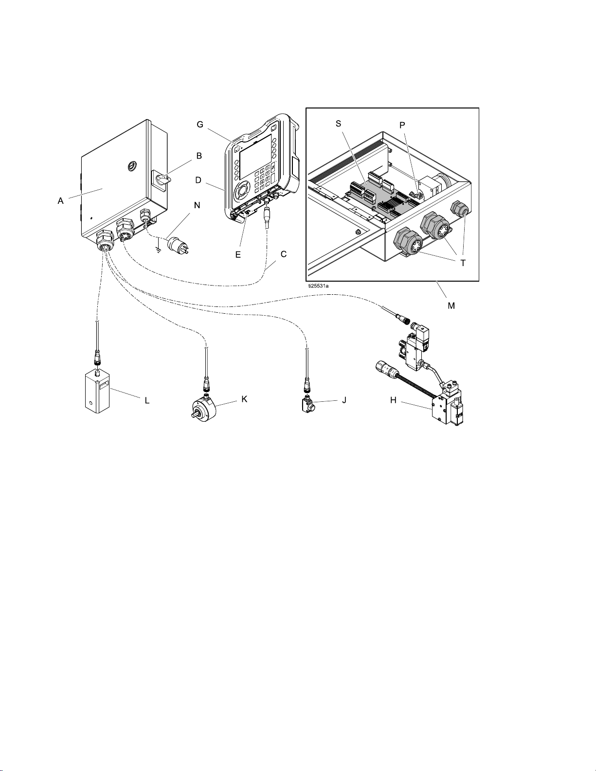
ComponentIdentication
Component
Component Component
Identication
Identication Identication
Key
Key Key
A
B
CCommunicationCable
DADM
E
G
HValve
JTrigger
PatternController
PowerSwitch
USBPort
IndicatorLight
Key
Key Key
KEncoder
LRunUp
M
N
P
SControlBoard
T
InsideViewofPatternController
PowerSupply
GroundTerminal
CordGrips(I/Ox2,power)
8 334784A
Page 9
Installation
Installation
Installation Installation
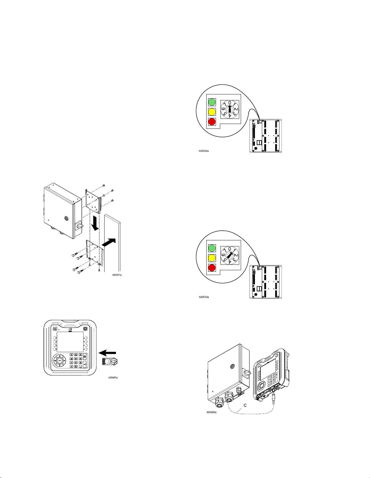
Mounting
Mounting Mounting
ThePatternControllerandADMcanbemounted
usingtheincludedVESA-compatiblebracketand
mountinghardware.
1.Unscrewthetwolowerscrewstouncouplethe
“wall”portionofthebracket.
2.Securelymountthebracketinthedesired
location.
3.Slidethecontrollerontothebracketandtighten
thetwoscrewsforpermanentfastening.
ALTERNATIVE
ALTERNATIVE ALTERNATIVE
hardwareandmountdirectlytoanysurface.
METHOD:
METHOD: METHOD:
removemounting
Connect
Connect Connect
(ADM)
(ADM) (ADM)
Integrate
Integrate Integrate
1.SetPatternControlboarddialpositionto0.
2.Unplugtheendofthecommunicationcablefrom
theADM,thenconnecttheshortcommunication
cabletotheADMandsplittertotheendof
thiscable.ConnectthePatternControllerand
InvisiPaccommunicationcablestothesplitter.
Stand
Stand Stand
Advanced
Advanced Advanced
with
InvisiPac
with with
InvisiPac InvisiPac
Alone
Alone Alone
Display
Display Display
Module
Module Module
Key
Token
Key Key
Token Token
ForPC-8emodels,installtheKeyTokenintheADM.
334784A 9
1.SetthePatternControlboarddialpositionto1.
2.MounttheADMusingtheprovidedbracket.
3.Connectthecommunicationcablebetweenthe
PatternControllerandtheADM.
Page 10
Installation
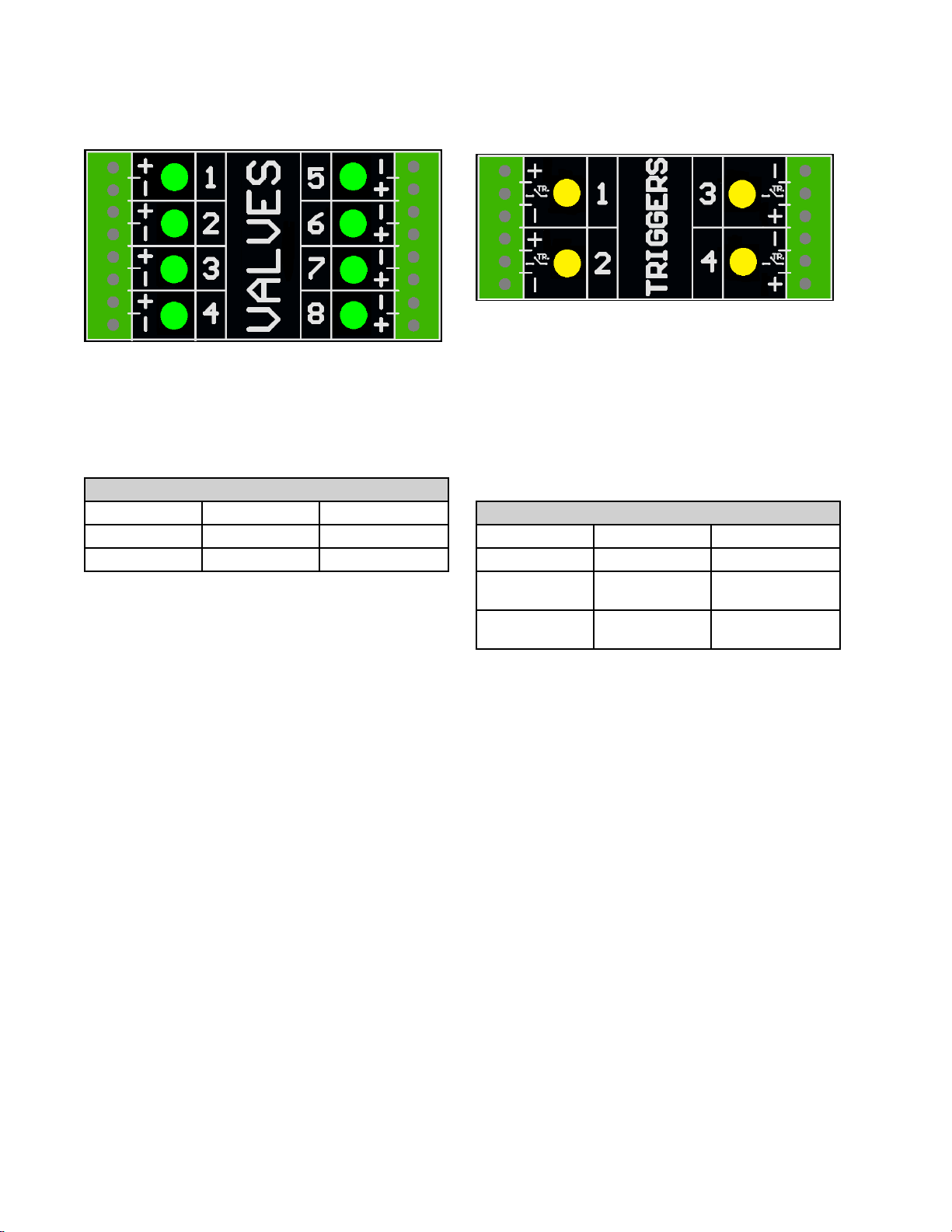
Valve
Valve Valve
1.Connectupto8valves.
Terminal
Terminal Terminal
Plus(+)24VSupply
Minus(-)
Installation
Installation Installation
NOTE:
NOTE: NOTE:
ampperoutputand6ampstotal.
NOTE:
NOTE: NOTE:
valve.
Controlvoltageis24VDCwithalimitof1
GreenLEDsindicatethestatusofeach
Standard
Standard Standard
Cable
Cable Cable
ReturnBrown/BlueM8
Trigger
Trigger Trigger
1.Connectupto4NPN,PNP,ordrycontact
triggers.
NOTE:
NOTE: NOTE:
2.ConnectthetwowiresbetweenTRandminus(-)
toinstalladrycontact.
NOTE:
NOTE: NOTE:
trigger.Polaritycanbeinvertedifneeded(see
Wiring
Wiring Wiring
Function
Function Function
Colors
Colors Colors
M8
or
M8 M8
or or
Black/BlueM12
M12
Cable
M12 M12
Cable Cable
TriggerSetup(Screen3),page23).
Terminal Terminal
Plus(+)24VSupply
TRNPN,PNP,or
Minus(-)Return(orDry
Installation
Installation Installation
Suppliedvoltage(+)is24VDC.
YellowLEDsindicatethestatusofeach
Standard
Standard Standard
Terminal
DryContact
Contact)
Wiring
Wiring Wiring
Function
Function Function
Colors
Colors Colors
M8
or
M12
M8 M8
Brown
BlackorWhite
Blue
or or
Cable
M12 M12
Cable Cable
10 334784A
Page 11
Installation
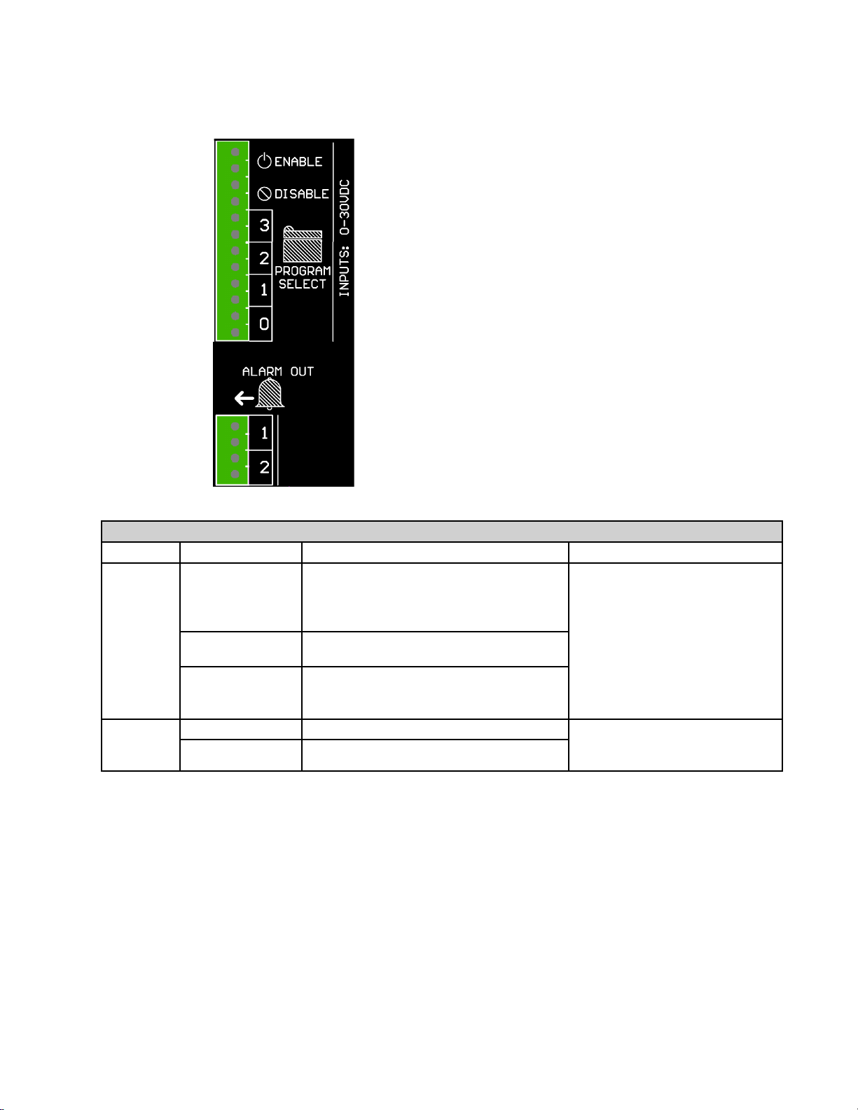
PLC
PLC PLC
Inputs
Inputs Inputs
and
Outputs
and and
Outputs Outputs
Installation
Installation Installation
(optional)
(optional) (optional)
1.IntegratewithaPLCbyusingtheseinputsand
outputs.
2.Inputsarebipolarandaccepta0VDCto30VDC
signal.Eachinputiselectricallyisolated.To
connectadrycontactsignal,route24VDCto
oneterminalandconnectthegroundthroughthe
drycontacttotheotherterminal.
3.Outputsaredrycontactandopeninthecaseof
analarm.
PLC
Inputs
PLC PLC
Inputs Inputs
Type
Type Type
Input
Output
Function
Function Function
ENABLE
DISABLE
PROGRAM
SELECT
ALARM1
ALARM2
Turnsthecontrolleronandoff(rising
edgeenables,fallingedgedisables).The
controllerwillwaitforarisingedgeto
re-enableafteranalarmorpowerreset.
Disablesthecontroller.Pullhighto
disable.
Bitsselectaprogramtorun(1–15)
i.e.1010selectsprogram#10
NOTE:0000disablesPLCselection
RelayopensforactivealarmsonLine1
RelayopensforactivealarmsonLine2
and
Outputs
and and
Outputs Outputs
Description
Description Description
Bipolarinput
0–30VDC
Min.10VDCtoassert.
Sinks10mAat24VDC.
Drycontactoutput
0–24VDCor0–240VAC
2Amax
Specs
Specs Specs
334784A
11
Page 12
Installation
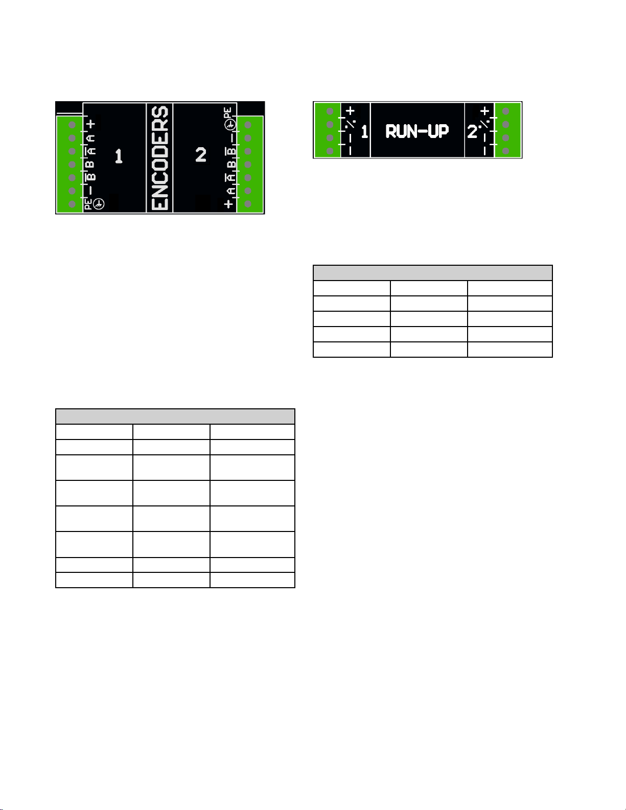
Encoder
Encoder Encoder
1.Connectuptotwoencoderstomonitorline
speed.NOTE: NOTE:
2onthescreen.
NOTE:
NOTE: NOTE:
differentiallinedriver(RS422).Scalingisentered
intheencodersetupscreenusingthelive
calibrationfeature.
NOTE:
NOTE: NOTE:
connections.Thesearenotusedanddonot
needtobeconnected.
NOTE:
NOTE: NOTE:
swappingAandA’withBandB’.Dothislineif
linespeedreadsnegativeonthedisplay.
Terminal
Terminal Terminal
Plus(+)15VSupply
APhaseAsignal
A’PhaseAsignal
BPhaseBsignal
B’PhaseBsignal
Minus(-)
PE
Installation
Installation Installation
NOTE:
Encodertypemustbequadrature
SomeencodershaveZandZ’
Encoderdirectioncanbereversedby
Graco
Graco Graco
TheseareusedforLine1orLine
Encoder
Encoder Encoder
Function
Function Function
(RS422)
return
(RS422)
return
ReturnBlue
Shield
(PC
8e
(PC (PC
- --8e 8e
Wiring
Wiring Wiring
Diagram
Diagram Diagram
Wire
Wire Wire
Red
Brown
White
Yellow
Green
Bare
only)
only) only)
Color
Color Color
Run
Up
Run Run
1.Connectuptotwo“I/P”or“V/P”run-upair
pressureregulatorstovarypumppressurebased
onlinespeed.Hardwareautomaticallydetects
whetheranI2PorV2Pisconnected.
NOTE:
NOTE: NOTE:
enteredontherun-upsetupscreen(seeRunUp
Control(Screens6–7,PC–8eonly),page26).
Terminal
Terminal Terminal
Plus(+)24VSupply
%Outputtorun-up
Minus(-)
Minus(-)
Installation
Up Up
Installation Installation
Pressurevs.linespeedsettingsare
Standard
Standard Standard
ReturnBlue
ReturnWhite
(PC
8e
(PC (PC
Wire
Colors
Wire Wire
Colors Colors
Function
Function Function
only)
- --8e 8e
only) only)
M12
M12 M12
Brown
Black
Cable
Cable Cable
12
334784A
Page 13
Installation
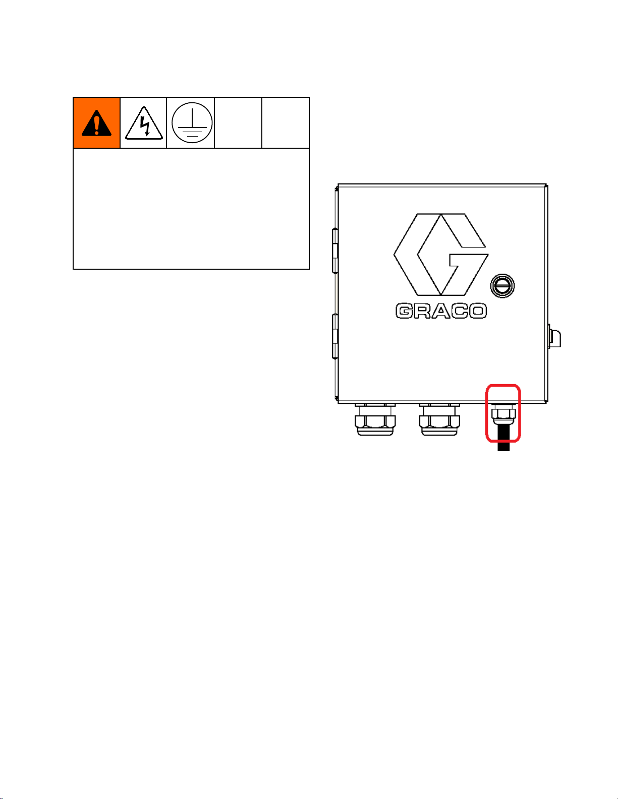
Connect
Connect Connect
Improperwiringmaycauseelectricshockorother
seriousinjuryifworkisnotperformedproperly.
Haveaqualiedelectricianperformanyelectrical
work.Besureyourinstallationcomplieswithall
National,State,andLocalsafetyandrecodes.
Theequipmentmustbegroundedtoreducethe
riskofelectricshock.Impropergroundingcan
causeelectricshock.Groundingprovidesan
escapewirefortheelectriccurrent.
TheInvisiPacsystemisequippedwithaground
terminal.Haveaqualiedelectriciangroundthe
systemusingthisterminal.
Electricalpowerentersthroughthesmallercord
gripontherightsideoftheenclosure(seebelow).
Thepowercordcanbefurthersecuredinsidethe
enclosurewiththeprovidedzip-tieandtiemount.
Electrical
Electrical Electrical
Cord
Cord Cord
1.Installpowerwires(L1/L2orL/N)intoterminals
2and4onthedisconnectswitch.Theswitch
acceptssolidorstranded12AWGand14AWG
wire.Forratings,seeTechnicalData,page46.
2.Connectearthgroundtothegroundingterminal.
3.Verifythatthecordgripsecurelytightensaround
thecord.Useawrenchtotighten,ifnecessary.
334784A 13
Page 14
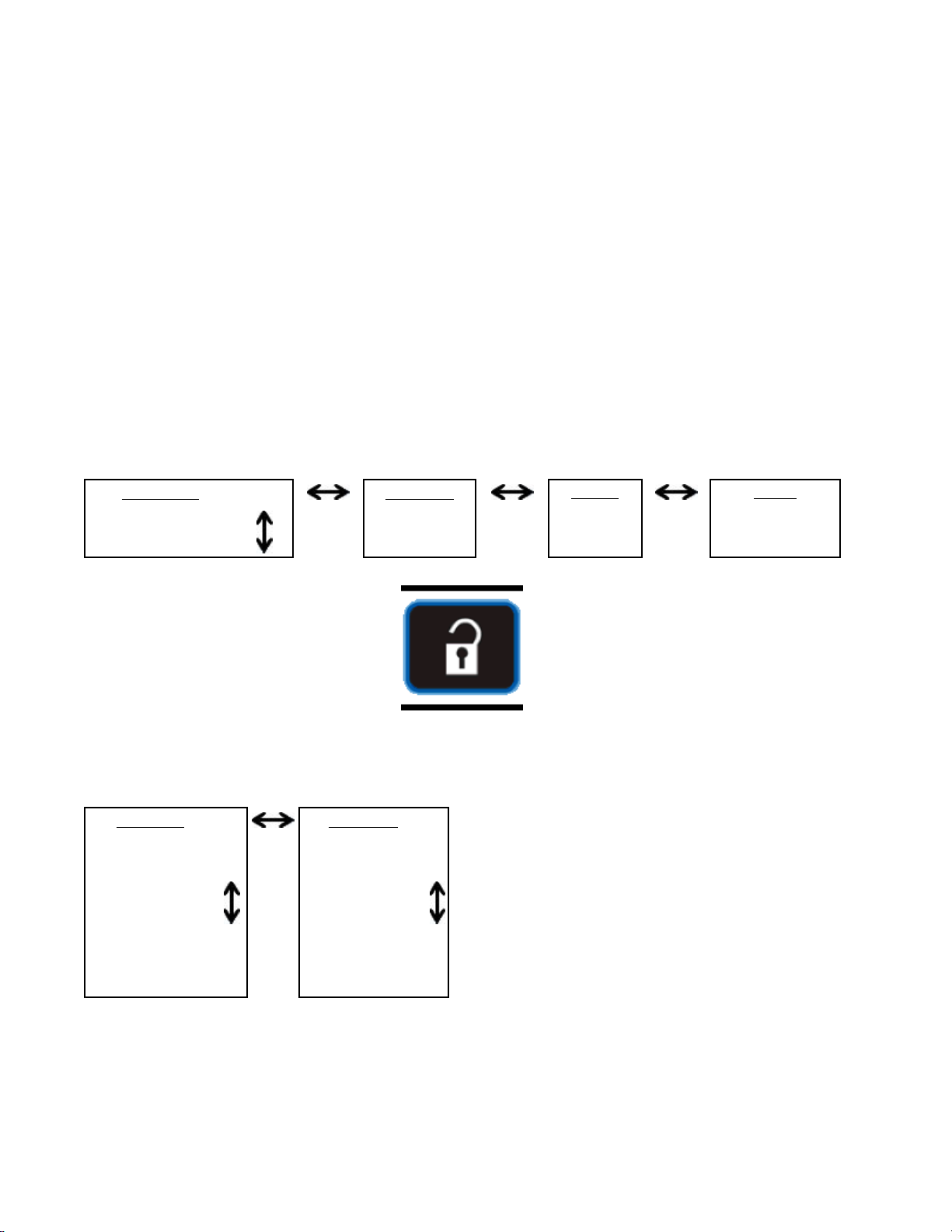
Screens
Screens
Screens Screens
NavigatethrougheachscreentosetupthePattern
Controllerinterface.
•Runscreensincludethehomepageandpattern
denition.
•Setupscreenscontaincongurablesettingsfor
eachaccessory.
Screen
Screen Screen
NOTE:
NOTE: NOTE:
chaptersarepresentforhotmeltHMI.
Run
Run Run
1.ProgramStorage
2.PatternDenition
Setup
Setup Setup
Maps
Maps Maps
OnintegratedInvisiPacsystem,additional
Screens
Screens Screens
PC
Control
PC PC
Control Control
Screens
Screens Screens
PC
Setup
PC PC
Setup Setup
PC
Home
PC PC
Home Home
PresstoswitchbetweenRunandSetup
Advanced
Advanced Advanced
Events
Events Events
Errors
Errors Errors
1.EventMap
2.LineMode
3.TriggerSetup
4.General
5.GunSetup
6.RunUp
14
1.Display
2.Units
3.USBSettings
4.Software
334784A
Page 15
Screens
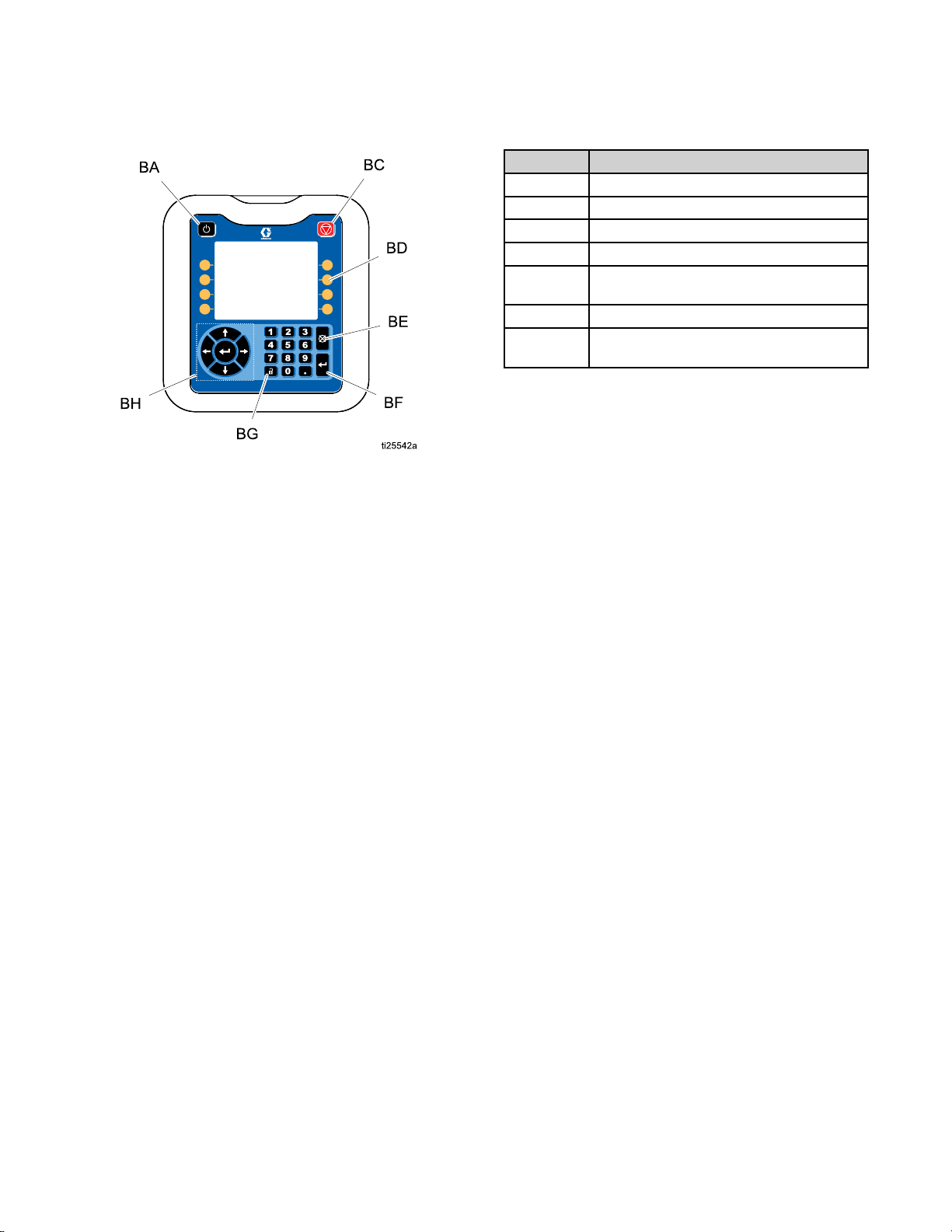
HMI
HMI HMI
Interface
Interface Interface
Key
Key Key
BA
BCStopallsystemprocesses
BD
BEAbortcurrentoperation
BFAcceptchange,acknowledgeerror,
BGTogglebetweenRunandSetupscreens
BHNavigatewithinascreenortoanew
ControllerEnable/Disable
Denedbyiconnexttosoftkey
selectitem,toggleselecteditem
screen
Function
Function Function
334784A 15
Page 16

Screens
PC
Screens
PC PC
Screens Screens
Home
Home Home
Readonlyviewofpatterncontrollerinputsandoutputs:
1.Statusofguns,triggers,andPLCsignals.
2.Productionrate
3.Materialdispensedperproduct
A AA—GunStates
B BB—TriggerStates
C CC—LineInformation
D DD—PLCSignals
Icon
Name
Icon Icon
Name Name
GunGunstatus:Active(green),Enabled(gray),Disabled(crossedout).
Trigger
LineNumber
,andunitscompleted.
.
Description
Description Description
TriggerStatus:Active(brightyellow),Inactive(darkyellow).
Linenumberforotherdisplayvaluesinrow.
LineSpeedCurrentlinespeed(orxedlinespeedsetting).
RunUpOutputPercentageofrunuppressurerangebeingoutput(PC-8eonly).
%
ProductionRate
ProductCountTotalproductscompleted.Sameascurrenttriggercyclecount.
GlueRateAmountofglueperproduct(integratedInvisiPacsystemsonly).NOTE: NOTE:
PLCEnableEnables/disablesthepatterncontrolviaPLC.
PLCDisableDisablesthesystemviaPLC.
ActiveProgram
PLCAlarmAlarmsbeinggiventothePLC(online1or2).
Numberofproductperminute.
bestresults,entertheappropriatespecicgravityvaluefortheadhesive
materialinuse(seetheInvisiPacsystemmanual).
DisplaystheactiveprogramchosenbythePLC.
16 334784A
NOTE:
For
Page 17

Screens
Program
Program Program
1.Selectprogramtoload.
2.Copyprogram,eraseprogram,orrenameprogram.
3.Purgeguns
4.Lock/unlockcontrollerformaintenance
NOTE:
NOTE: NOTE:
GeneralSetup(Screen4),page24).
A AA—EnterScreen
B BB—MaintenanceLock/Unlock
C CC—ToPurgeScreen
D DD—ActiveProgram
P PP—ScreenNumber(Screen1)
Storage
Storage Storage
Copy,erase,andrenamecapabilitiesaredisabledif“LockPatternDenition”isenabled(see
(Screen
(Screen (Screen
.
1)
1) 1)
.
Icon
Name
Icon Icon
Name Name
MaintenanceLock
MaintenanceUnlock
E EE—ExitScreen
F FF—CopySelected
G GG—EraseSelected
H HH—RenameSelected
J JJ—Press“Enter”toSelectActiveProgram
Description
Description Description
PresstodisablePatternController
PresstoenablePatternController
334784A
17
Page 18

Screens
Gun
Purge
Gun Gun
Purge Purge
1.Purgeindividualguns.
2.Purgeallgunsbypressingenter.
NOTE:
NOTE: NOTE:
NOTE:
NOTE: NOTE:
A AA—PresstoPurge
B BB—DisabledGunswillnotPurge
Onlygunswithassignedtriggerswillpurge.
Gunsmayonlybepurgedwhenthesystemisactiveorwithin5minutesofthesystembeingactive.
Icon
Name
Icon Icon
Name Name
Purge
EnterPurgeallenabledguns
Return/Cancel
Description
Description Description
Purgespecicgun
Exitscreen
18 334784A
Page 19

Screens
Pattern
Pattern Pattern
1.Enterstartpointandlengthofbeads.
2.Enableordisablestitchingforeachbead.
3.Previewthispattern.
NOTE:
NOTE: NOTE:
numberkeyforgunA.
NOTE:
NOTE: NOTE:
beads6–24.
—
A AA— —
—
B BB— —
—
C CC— —
—
D DD— —
—
E EE— —
—
P PP— —
Denition
Denition Denition
ToclonethepatternfromgunAtogunB,navigatetoanybeadongunBandpress/holdthe
Enterthescreenandscrolldowntoseevalves5–8.Addbeadsandcontinuetoscrollrighttoaccess
EnterScreen
PatternPreview
Dots=Stitched
Solid=SolidBead
CurrentProgram
StartofBead
BeadLength
ScreenNumber
(Screen2)
(Screen
(Screen (Screen
2)
2) 2)
F FF—ExitScreen
G GG—ConrmChanges
H HH—CancelChanges
J JJ—StitchBead
Icon
Icon Icon
Name
Name Name
BeadOffsetDistancefromtheedgeoftheproducttothestartofthebead
BeadLength
StitchBeadEnableordisablestitchingofthisbead.
Description
Description Description
LengthoftheBead
334784A 19
Page 20

Screens
Pattern
Pattern Pattern
Read-onlydisplayofbeadpattern.
A AA—EndpointofLastBead
B BB—ExitPreview
—GunNumber
—TriggerNumber
NOTE:
NOTE: NOTE:
NOTE:
NOTE: NOTE:
gundoesnothaveatriggerselected(see
EventMap(Screen1),page21).
Preview
Preview Preview
Dottedpatternshowsstitching.Theactualnumberofstitchedbeadsisnotrepresented.
Areddottedpatternindicatesthatthe
20 334784A
Page 21

Screens
Event
Event Event
Entercongurationsettingsforthispattern:
1.Assigntriggertoeachgun.
2.Inputgun-to-triggeroffset.
3.Enterminimumproductlength(iffalsetriggerpickupisaconcern).
4.Enablepatternmirroring.
5.Enterstitchpercentageandinterval.
A AA—EnterScreen
B BB—GunNumber
C CC—TriggerforGun
D DD—GuntoTriggerOffset
E EE—MinimumProductLength
F FF—CurrentProgram
G GG—StitchInterval
H HH—StitchSavings
J JJ—MirrorPattern
P PP—ScreenNumber(Screen1)
Map
(Screen
Map Map
(Screen (Screen
1)
1) 1)
Icon
Name
Icon Icon
Name Name
TriggerTriggerassociatedwiththisgun
Gun-to-TriggerOffset
MinimumProduct
Length
MirrorBeadPattern
StitchSavingsPercentageofgluesavedbystitching.Setto0todisablestitching.
StitchIntervalThedistancebetweenthestartofeachstitch.
Description
Description Description
Thephysicaldistanceortimebetweenthetriggerandthegun.
Blockstriggersfromactivatingasecondpatternwithintheminimumproduct
length
Mirrorsbeadsfromtheleadingedgeoftheboxtothetrailingedgeofthebox.
NOTE:
NOTE: NOTE:
halfthelengthofthebox(seeMirrorMode,page33).
NOTE:
NOTE: NOTE:
Stitching,page29).
Ifmirrormodeisselected,theGun-to-TriggerOffsetmustbeatleast
Stitchingmustalsobeenabled/disabledforeachbead(see
334784A
21
Page 22

Screens
Line
Mode
Line Line
Mode Mode
(Screen
(Screen (Screen
2)
2) 2)
b.Adjustlinespeedsetting
untillengthof
1.Selectmode:
a.Timebased.
b.Distancemodewithoutencoder(usesxed
linespeed).
c.Distancemodewithencoder.
2.Fortimemode,therearenoadditionalsettings.
3.Fordistancemodewithoutencoder:
a.Passoneproductbythetriggeratnormal
speed.
NOTE:
NOTE: NOTE:
nottrippingthetriggerproperly.
A AA—EnterScreen
B BB—LastBoxLength
P PP—ScreenNumber(Screen2)
Seetriggersetupsectionifproductis
lastproductiscorrect.
4.Fordistancemodewithencoder.
a.Verifypositivelinespeedwhenlineismoving
forward.Ifspeedisnegative,swapAandA’
withBandB’wiresattheencoderconnector
onthePatternController.
b.Passoneproductbythetrigger.
c.Adjustencoderpulsespermm
lengthoflastproduct
until
iscorrect.
Icon
Name
Icon Icon
Name Name
Time
Based
TimeModeSelectIntimemode,programssettingsareinunitsofmilliseconds
LineNumber
LengthofLastProductLengthofthelastproductseenbyatriggerontheline.
Encoder
EncoderPulsesper
mm
LowLineSpeedAlarmOutputswillnotrewhenthelineisbelowthisspeed.
HighLineSpeed
Alarm
LineSpeed•Ifencoderenabled:viewcurrentlinespeed
Description
Description Description
Linenumberforothersettings/valuesinarow
NOTE:
NOTE: NOTE:
Selectifencoderistobeused
Pulsesencodergeneratespermmoflinetravel.
NOTE:
NOTE: NOTE:
NOTE:
NOTE: NOTE:
Read-only:Maximumlinespeedallowed.
NOTE:
NOTE: NOTE:
•Ifencoderdisable:enterxedlinespeed
Valueadjustsforchangesinencoder/speedsettings.
500pprencoder,200mmwheel=2.5pulses/mm.
Avalueof0disablesthisalarm.
Thevalueiscalculatedfromencoderpulsespermm.
22
334784A
Page 23

Screens
Trigger
Trigger Trigger
1.SelectTriggerPolarity
2.SelectTriggerLineNumber
A AA—EnterScreen
B BB—TriggerPolarity
C CC—Line1or2
D DD—ResetSelectedCounter
E EE—LifetimeTriggerCount
F FF—ResettableTriggerCount
P PP—ScreenNumber(Screen3)
Setup
Setup Setup
a.Triggershouldshowbrightyellowwhen
productispresentanddarkyellowforno
product.
b.Ifpolarityisbackwards,usethedrop-down
a.Ifproductrunspastalltriggersatthesame
speed,selectline1.
toinvertthedetection.
(Screen
(Screen (Screen
3)
3) 3)
b.Wheretwolinespeedsettingsarerequired,
selectline1fortriggerssensingfromtherst
:
3.TriggerCycleCounters:
(PC-8eonly):
linespeedandline2forthesecond.
a.Viewcurrentandlifetimecyclecountsof
eachtrigger.
b.Presssoftkey
countofselectedtrigger.
toresetcurrentcycle
Icon
Name
Icon Icon
Name Name
TriggerPolarity
SelectLineSelectwhichlinethetriggerissensingon(PC-8eonly)
ResetCounter
Description
Description Description
Togglepolaritytoinvertstateoftriggersignal
Resettriggercyclecount
334784A 23
Page 24

Screens
General
General General
1.LockPatternDenition(optional)—Protects
2.EnablePressureCompensation(optional,PC-8e
Setup
Setup Setup
patternfromaccidentalchanges.Operatormust
enterapasswordtochangepatterns,andcopy,
delete,orrenameprograms.
NOTE:
NOTE: NOTE:
ifRunScreensarealsolocked(see
AdvancedScreens,page27).
only):
•Usedtomaintainconsistentglueoutputwith
variablelinespeed.
•Withrun-upkitinstalled,thisfeatureadjusts
pumppressureaccordingtotheoutput
vs.speedcurve.Forrun-upsettings,see
RunUpInstallation(PC-8eonly),page12.
(Screen
(Screen (Screen
Thissettingwillonlytakeeffect
4)
4) 4)
3.EnableModulatedBead(optional,PC-8eonly):
•Usedtomaintainconsistentglueoutputwith
variablelinespeed.
•Adjustsoutputbystitchingbeadsaccordingto
theoutputvs.speedcurve.
•WhenPressureCompensationisenabled,
modulatedbeadbecomesactivebelowthe
minimumoutputpercentage.
•WhenPressureCompensationisdisabled,
modulatedbeadfollowstheoutputvs.
speedcurve.Forrun-upsettings,see
RunUpInstallation(PC-8eonly),page12.
A AA—EnterScreen
P PP—ScreenNumber(Screen4)
24
334784A
Page 25

Screens
Gun
Setup
Gun Gun
Setup Setup
1.GunCompensation:
(Screen
(Screen (Screen
5)
5) 5)
•Viewcurrentandlifetimecyclecountsofeach
gun.
•Entergunopencompensation.
•Entergunclosecompensation.
2.GunCycleCounters:
A AA—EnterScreen
B BB—GunOpenCompensation
C CC—GunCloseCompensation
D DD—LifetimeGunCycles
E EE—ResettableGunCycles
P PP—ScreenNumber(Screen5)
Icon
Name
Icon Icon
Name Name
OpenCompensationMechanicaldelaybetweenelectricalsignaltogunandphysicalopeningofgun
CloseCompensationMechanicaldelaybetweenelectricalsignaltogunandphysicalclosingofgun
ResetCounter
Description
Description Description
Resetguncyclecount
•Presssoftkey
counterofselectedgun.
toresetcurrentcycle
334784A 25
Page 26

Screens
Run
Up
Run Run
•Enterrunupoutputsettings
A AA—EnterScreen
B BB—MinimumOutput
C CC—MaximumOutput
D DD—HighCalibrationPoint
E EE—LowCalibrationPoint
P PP—ScreenNumber(Screen6)
Icon
Icon Icon
Control
Up Up
Control Control
Name
Name Name
OutputPressure
Percentage
LineSpeed
(Screens
(Screens (Screens
6–7,
PC–8e
6–7, 6–7,
PC–8e PC–8e
Description
Description Description
Enterminimumandmaximumpressureforrunupcontrol.
Entercorrespondingpressurepointsforenteredlinespeedpointstosetrun
upcurve.
UpperandLowerlinespeedpoints
only)
only) only)
RunUpPressureto
LineSpeedCurve
Curveissetbytwopointswhicharedenedbytheuser.Upperandlower
limitsdeneboundsoverwhichrun-upwillfunctionlinearly.
26 334784A
Page 27

Screens
Advanced
Advanced Advanced
Advanced
Advanced Advanced
Generaldisplaysettingsincludinglanguage,time,
andpasswordprotection.
Name
Name Name
Language
DateFormat
DateEnterthedisplaydate
TimeEnterthedisplaytime
PasswordEnterthepasswordtorestrict
ScreenSaverEnterthetime-outforthedisplay
SilentModeIfselected,disablesthedisplay
LockRun
Screens
Screens
Screens Screens
—
Display
— —
Display Display
Description
Description Description
Selectthedisplaylanguage
Selectthedisplaydateformat
accesstoSetupscreens.NOTE: NOTE:
Avalueof“0000”doesnotrequire
apasswordforaccesstosetup
screens.
screensaver.NOTE: NOTE:
disablesthescreensaver.
beepfunctionality.
Ifselected,operatorswillnotbe
abletochangemostrunscreen
settings.NOTE: NOTE:
thissettingtohaveanyeffect,a
passwordotherthan“0000”must
beenteredabove.
NOTE:
NOTE:
Inorderfor
NOTE:
Avalueof“0”
Advanced
Advanced Advanced
Selectthesystemunitstobeusedonthedisplay.
Name
Name Name
Temperature
MassUnits
SpecicGravityEnterthematerialspecicgravity
DistanceUnits
—
Units
— —
Units Units
Description
Description Description
Selectthesystemtemperature
units(integratedsystemsonly)
Selectthesystemmassunits
(integratedsystemsonly)
forhigherprecisionadhesive
consumption(integratedsystems
only)
Selectthesystemdistanceunits.
NOTE:
NOTE: NOTE:
patterncontroldistancevalues
exceptwhentimebasedmodeis
selectedon
(distanceunitsbecometimeunits
ofmilliseconds).
Thissettingappliestoall
PC Setup – Line Mode
334784A
27
Page 28

Screens
Advanced
Advanced Advanced
SelectUSBdownloadsettings.
Name
Name Name
DisableUSB
Downloads/
Uploads
DisableUSBLog
Errors
DownloadDepth
—
USB
— —
Downloads
USB USB
Downloads Downloads
DisablesUSBportfrom
transmittingdatato/fromaUSB
drive
DisablesUSBlogadvisory
Setsthelengthofthedatalogs
tobedownloaded(affectsthe
downloadtime)
Settings
Settings Settings
Description
Description Description
Advanced
Advanced Advanced
Readonlydisplayofsystemsoftware.
Name
Name Name
Module
SoftwarePart#Partnumberofsoftwareinstalled
SoftwareVersionVersionofsoftwareinstalledon
NOTE:
NOTE: NOTE:
donotmatchtheexpectedvalues,see
SoftwareUpdateProcedure,page40.
—
System
— —
System System
Nameofmoduleinsystem
onmodule
module
Ifsoftwareversionsorpartnumbers
Software
Software Software
Description
Description Description
28 334784A
Page 29

Stitching
Stitching Stitching
Tomaintainbondstrengthwhilereducingadhesiveconsumption..
Denitions
Denitions Denitions
Stitching
Sub-Bead
Sub-Bead Sub-Bead
Onedispensecycleofastitchedbead.
Stitch
Stitch Stitch
Thedistancebetweenthestartsoftwoadjacentsub-beads.
Stitch
Stitch Stitch
Thepercentageofadhesivesaved.
Anchor
Anchor Anchor
Ananchorbeadisasub-beadplacedattheendofthestitchedbeadthatguaranteesthestitchedbeadendsat
thesamelocationastheoriginal(non-stitched)bead.
—
— —
Interval
Interval Interval
Savings
Savings Savings
—
— —
—
— —
Beads
Beads Beads
Setup
Setup Setup
Inordertostitchanybead,performthefollowing
steps:
1.NavigatetoEventMap(Screen1),page21.
2.EnterthedesiredStitchInterval
Savings
Stitchingcanbedisabledbysettingthegun
StitchSavingsto“0”.
334784A 29
forthedesiredgun.NOTE: NOTE:
andStitch
NOTE:
3.NavigatetoPatternDenition(Screen2),page
19.
4.StitchindividualbeadsbyselectingtheStitch
Bead
NOTE:
NOTE: NOTE:
stitched(somecanbestitchedwhileothersare
solid).
optionwithineachbeadentrybox.
Notallbeadsforaspecicgunmustbe
Page 30
LineSpeed
Line
Line Line
1.NavigatetoLineMode(Screen2),page22.
2.Passaproductofknownlengthpastthetrigger
3.Oncetheproducthaspassedthetrigger,note
Speed
Speed Speed
inuse.
thevaluedisplayedinthe
indicator.NOTE: NOTE:
ofthepartoftheproductthatpassesbelowthe
triggerinuse,notnecessarilytheoveralllength
oftheproduct.
NOTE:
Last Product Length
Thisvalueisthelength
4.Adjustsettings:
a.Onencoder encoder
b.Onxedline line
NOTE:
NOTE: NOTE:
accordingtothechangesmadeinsettingsabove
(step2onlyneedstobeperformedonce).
encoder
Encoder Pulses per mm
ProductLengthvaluematchestheexpected
length.
adjust
Product Length
length.
Last Product Length
line
Fixed Line Speed
systems
systems systems
speed
speed speed
valuematchestheexpected
(PC-8eonly),adjust
systems
systems systems
indicatorwillupdate
untiltheLast
(bothversions),
untilthe
Last
Last Product Length
incheslong.
displayedfortriggeris18.00
Encoderpulsespermmbox.
FixedLineSpeedbox.
30 334784A
Page 31

RunUpControl
Run
Run Run
Run
Run Run
1.Verifyrunupcontrollerrangeissetto100psi(10
2.NavigatetoGeneralSetup(Screen4),page24,
High
High High
1.TurnsystemONandrunlineatmaximumspeed.
2.NavigatetoLineMode(Screen2),page22,and
3.Setpressureusingthepumppressuredialand
4.NotepressuredisplayedonInvisiPacpump
5.Notepressuredisplayedonrunupcontrollerin
Up
Up Up
Up
Up Up
Vinputsignalyields100psi).NOTE: NOTE:
belowassumeinputairpressuretotheregulator
isgreaterthanorequalto100psi(simpliesrun
upprogrammingsothat%andpsivaluesare
interchangeable).
anddisablePressureCompensation.
Calibration
Calibration Calibration
noteCurrentLineSpeedinFbelow.
gaugeatthebaseoftheInvisiPacsystemuntil
thedesiredglueoutputisachieved.
pressuregaugeinG GGbelow.
B BBbelow.
Control
Control Control
Setup
Setup Setup
NOTE:
Point
Point Point
settings
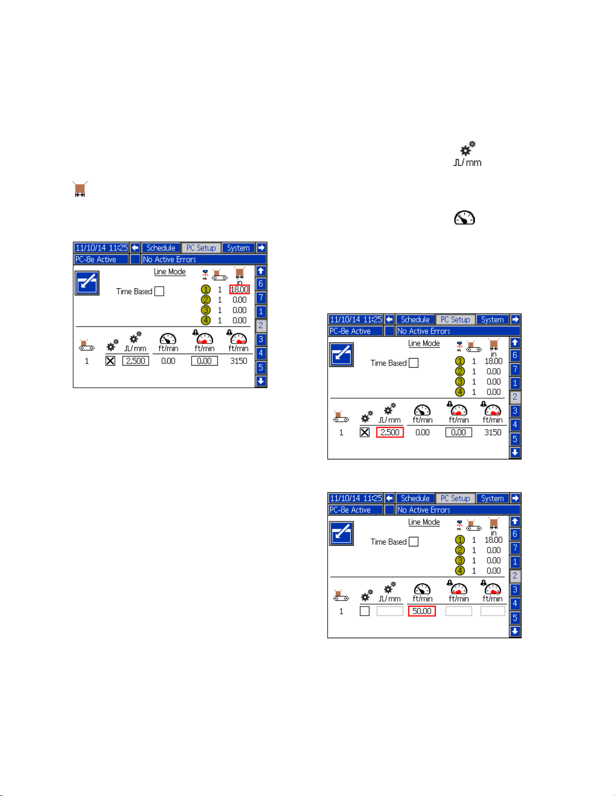
User
User User
1.NavigatetoRunUpControl(Screens6–7,PC–8e
2.NavigatetoGeneralSetup(Screen4),page
User
User User
(A)
(A) (A)
(B)
(B) (B)
(C)
(C) (C)
(D)
(D) (D)
(E)
(E) (E)
(F)
(F) (F)
(G)
(G) (G)
Setting
Setting Setting
only),page26.Entersettingsinscreenshot
accordingtovaluesinsectionbelow.
24andre-enablePressureCompensation.
Settings
Settings Settings
Maximumoutput_____100
Runupcontroller
pressureathighline
speed
Runupcontroller
pressureatlowline
speed
Minimumoutput______50
Lowlinespeed
Highlinespeed
InvisiPacpump
pressureathighline
speed
Entry
Entry Entry
________
________
________
________
________
%(psi)
%(psi)
%(psi)
%(psi)
ft/minor
m/min
ft/minor
m/min
psi
Low
Low Low
1.Reducelinespeedtominimumspeedandnote
2.Reducepressureusingthedialandgaugeatthe
3.ReturnpressureonInvisiPacpumppressure
334784A 31
Calibration
Calibration Calibration
CurrentLineSpeedinE EEbelow.
baseoftheInvisiPacsystemuntilthedesired
glueoutputisachieved.Notepressuredisplayed
onregulatorinC CCbelow.
gaugetovalueinG GGbelow.
Point
Point Point
PCSetup—RunUpControlscreenwithsettings
indicatedbythelettersabove.
Page 32

RunUpControl
Random
Random Random
Forhandlingproductsofvariouslengthswithonepattern
Touserandomlengthbeadmode,performthefollowingsteps:
1.NavigatetoEventMap(Screen1),page21.
2.SelectMirrorBeadPatternforthedesired
gun.
3.VerifytheappropriateGun-TriggerOffset
fortheselectedgun.
NOTE:
NOTE: NOTE:
orequaltotheleadingmargin.
4.NavigatetoPatternDenition(Screen2),page
19.
Length
Length Length
Gun-TriggerOffsetmustbegreaterthan
Bead
Bead Bead
Mode
Mode Mode
5.Entertheleadingmargin(LM)inthebead1
offsetbox.NOTE: NOTE:
thetrailingmargin.
6.Enterthelengthofthelongestrandombead
(LRB)thatmaybeneededinthebead1length
box.
7.Enableordisablestitchingforbead1.
NOTE:
Theleadingmarginisequalto
32 334784A
Page 33

RunUpControl
Mirror
Mirror Mirror
Forsymmetricalpatterns,includingproductswith
varyinglengths.
Tousemirrormode,performthefollowingsteps:
1.NavigatetoEventMap(Screen1),page21.
Mode
Mode Mode
2.SelectMirrorBeadPattern
gun.
3.VerifyGun-TriggerOffset
gunisgreaterthanorequaltotheendofthenal
bead(nalbeadoffset+length).
4.NavigatetoPatternDenition(Screen2),page
19.
5.Enterbeadinformationforthersthalfofthe
product.
6.Enableordisablestitchingforeachbead.
forthedesired
fortheselected
334784A 33
Page 34

Calibration
Calibration
Calibration Calibration
Gun
Gun Gun
Forhighspeedlinesandprecisionapplications.
NOTE:
NOTE: NOTE:
ensuretheappropriategun-triggeroffsetvalues
havebeenenteredforeachgun-triggerpairon
EventMap(Screen1),page21.
Enteringtheappropriateguncompensationcan
ensurehigheraccuracyofbeadplacement.To
ensuretheappropriatevaluesareentered,begin
withthe
accordingtothe
Gun
Gun Gun
Compensation
Compensation Compensation
Beforeenteringguncompensationvalues,
(optional)
(optional) (optional)
Recommended Values
Calibration Routine
Compensation
Compensation Compensation
Relative
Relative Relative
Desired:
Adjustment
Adjustment Adjustment
Edge
Edge Edge
Position
Position Position
belowandadjust
Guide:
Guide: Guide:
.
Lagging
Recommended
Recommended Recommended
GM-100:5-10ms
GS-35:10–20ms
Unknown,other:10ms
Calibration
Calibration Calibration
1.NavigatetoGunSetup(Screen5),page25.
2.Dispensedesiredpattern(programcontained
withinthePatternController).
3.Measuredistancebetweendispensedpattern
(actualpositionofdispensedpatternonthe
product)anddesiredpattern.
4.AdjustOpen/Closecompensationvalues
accordingtothefollowingGun Gun
Table
Table Table
5.Repeatsteps2-3untildesiredpatternachieved.
Leading
Leading Leading
Edge
Edge Edge
Leading
Values
Values Values
Routine
Routine Routine
Gun
Compensation
Compensation Compensation
Gun
andGun Gun
Compensation
Compensation Compensation
Trailing
Trailing Trailing
Lagging
Formula
Formula Formula
Edge
Edge Edge
below.
Leading
vs.
Dispensed:
Adjustment
Gun
Compensation
Gun Gun
Compensation Compensation
Determinetheguncompensationadjustmentamountinmilliseconds.
Standard
Standard Standard
Metric
Metric Metric
Bead
Bead Bead
Compensation
Compensation Compensation
units:
units: units:
units:
units: units:
offset
distances
offset offset
distances distances
Gun
Gun Gun
(ms)
(ms) (ms)
5
5 5
10
10 10
20
20 20
Formula:
Formula: Formula:
Adjustment(ms)=
Adjustment(ms)=
inches
in inininches inches
50
50 50
15.24
15.24 15.24
0.05in.
1.27(mm)
0.1in.
2.54(mm)
0.2in.
5.08(mm)
(mm)
(mm) (mm)
ft/min
ft/min ft/min
(m/min)
(m/min) (m/min)
Increase
as
as as
a aafunction function
100
100 100
30.48
30.48 30.48
2.54(mm)
5.08(mm)
10.16(mm)
Decrease
5000xMeasuredOffsetDistance(in.)
LineSpeed(ft/min.)
60xMeasuredOffsetDistance(mm)
LineSpeed(m/min.)
function
0.1in.
0.2in.
0.4in.
ft/min
ft/min ft/min
(m/min)
(m/min) (m/min)
Gun
of ofofGun Gun
Compensation
Compensation Compensation
Line
Speed
Line Line
Speed Speed
200
ft/min
200 200
ft/min ft/min
60.96
(m/min)
60.96 60.96
(m/min) (m/min)
0.2in.
5.08(mm)
0.4in.
10.16(mm)
0.8in.
20.32(mm)
and
and and
IncreaseDecrease
Line
Line Line
500
500 500
152.4
152.4 152.4
0.5in,
12.7(mm)
1.0in.
25.4(mm)
2.0in.
50.8(mm)
Speed
Speed Speed
1000
ft/min
ft/min ft/min
(m/min)
(m/min) (m/min)
304.8
304.8 304.8
ft/min
1000 1000
ft/min ft/min
(m/min)
(m/min) (m/min)
1.0in.
25.4(mm)
2.0in.
50.8(mm)
4.0in.
101.6(mm)
34 334784A
Page 35

Verication
Verication Verication
Thissectionveriesproperinstallationofthe
InvisiPacPatternControlSystem.Forfurther
assistance,seeTroubleshooting,page36.
Encoder
Encoder Encoder
1.NavigatetoHome,page16.
2.VerifythatthelinespeeddisplayedintheCurrent
LineSpeedindicator
fordifferentlinespeeds.
ispositiveandvaries
Verication
Valves
Valves Valves
1.NavigatetoGunPurge,page18.
a.WithsystemON:attemptapurgeoneach
installedvalveandverifythatthevalveis
actuated(gluehasbeendispensedfromthe
appropriatevalve).
b.WithsystemOFF:disconnectthecable
fromthesolenoidandattemptapurge
oneachinstalledvalveandverifythatthe
signalisactuated(viatheLEDonthevalve
connector).
Triggers
Triggers Triggers
1.NavigatetoHome,page16.
2.Withoutproductinfrontofthetrigger,verifythat
thetriggerindicatorLEDisOFF.
3.Withproductinfrontofthetrigger,verifythatthe
triggerindicatorLEDisON.
3.Ifthelinespeedshowndoesnotmatchthe
known/expectedvalue,seeCalibration,page34,
tomaketheappropriateadjustments.
Run
Run Run
1.NavigatetoHome,page16.
2.TurnthesystemONandwaitforthePattern
3.Runthelineatvariousspeedsandverifythatthe
4.Ifthepercentage/pressuredisplayeddoesnot
PLC
PLC PLC
1.NavigatetoHome,page16.
Up
Control
Up Up
Control Control
ControllertobecomeACTIVE.
appropriateRunUpOutputisdisplayedonthe
screenandtheRunUpControllerisdisplayed(if
pressurereadoutisavailable).
matchtheexpectedvalue,seeRunUpControl
(Screens6–7,PC–8eonly),page26,tomakethe
appropriateadjustments.
Inputs
Inputs Inputs
2.ActuatethePLCinputremotelyandverifythat
theexpectedresultisindicatedinthePLCIO
sectionintheupperrightcornerofthedisplay.
334784A 35
Page 36

Troubleshooting
Troubleshooting
Troubleshooting Troubleshooting
Error
Error Error
Whenerroroccur,press
automaticallywhentheconditionthatcauseditiscorrected.Activeerrorsscrollonthemenubar
AlarmsshutdownthePatternControllerandactivatethedrycontactPLCoutput.Advisoriesanddeviations
areinformationalonlyanddonotshutthesystemdown.
CAXPCommunication
A40P
A4XP
A4_P
K4_PHighPulseRate
Codes
Codes Codes
toacknowledgeeacherror.Afterbeingacknowledged,theerrorwillclear
Alarms
Alarms Alarms
Code
Code Code
Description
Description Description
ADMunableto
Error
OvercurrentOvercurrenton
OvercurrentOvercurrenton
OvercurrentOvercurrentonvalve
communicatewith
PatternController
accessorypowersupply
output
communicationcable
output
output“_”
Encoder“_”pulserate
exceedsmaximumlimit
(shut
the
(shut (shut
Cause
Cause Cause
system
the the
system system
down)
down) down)
Solution
Solution Solution
CheckforgreenpowerlightonthePattern
Controller
Checkcommunicationcabling
Checkaccessorycablingforshortcircuit
CheckADMCANcablingforshortcircuit
Replacedisplay(ADM)
Checkwiringforshortcircuit
Verifyvalveresistanceishigherthan24ohms
Selectencoderwithlowerpulserate
Reducelinespeedorgearingratio
Advisories
Advisories Advisories
LowLineSpeed
Description
Description Description
Code
Code Code
V1_PLowVoltagePowersupplyvoltage
V4_PHighVoltagePowersupplyvoltage
K1_P
and
Deviations
and and
Deviations Deviations
Cause
Cause Cause
below18VDC
above28VDC
PoorEncoderCoupling
online“_”
LineSpeedislessthan
lowlinespeedalarm
levelonline“_”
(do
not
shut
the
(do (do
not not
shut shut
Tocheckforoverloadedpowersupply,
measurethevoltagewithallvalvesoff,and
thenwithallvalveson(purging).
Tocheckforoverheatedpowersupply,allow
theunittocoolandrecheckvoltage.
Adjustvoltageto24Vifpossible,orreplace
thepowersupply.
Adjustvoltageto24Vifpossibleorreplacethe
powersupply.
Checktoensurepropercouplingbetween
lineandencoder.VerifyPatterncontroller
isreadingappropriatelinespeed(see
LineMode(Screen2),page22).
Increaselinespeedordecrease
lowlinespeedalarmlevel(see
LineMode(Screen2),page22).
system
the the
system system
down)
down) down)
Solution
Solution Solution
36 334784A
Page 37

Troubleshooting
Display
Display Display
Problem
Problem Problem
Displaydoesnotturnon
PatternControlScreens
notpresent
RunUpControlScreens
notpresent
Encodersettingsnot
present
Pattern
Pattern Pattern
Problem
Problem Problem
Nopatterndispensed
Cause
Cause Cause
SelectordialonPatternControl
boardsettowrongposition
Powernotturnedon
CommunicationcabledisconnectedVerifyPatternControlboardisconnected
SelectordialonPatternControl
boardsettowrongposition
SoftwareversionmismatchPerformsoftwareupdateprocess
PC-8ekeytokennotinsertedinADMObtainPC-8ekeytoken(comeswith
Cause
Cause Cause
Valvenotassociatedwithcorrect
trigger(ornotassignedtoany
trigger)
Physicalproblemwithvalve
Improperstitchsettings
IntegratedSystems:setto0
Stand-AloneSystems:setto1
CheckforgreenlightonPatternControl
boardandDisplay
toDisplay
IntegratedSystems:setto0
Stand-AloneSystems:setto1
withlatestversionofsoftware(see
SoftwareUpdateProcedure,page40).
PC-8eversionsofInvisiPacPatternControl
System)
Ensurevalvehasappropriatetrigger
selected
See“NoGlueDispensed”troubleshooting
helpwithin
Stitch Interval
Solution
Solution Solution
Solution
Solution Solution
Valve
section
tooshortor
Stitch
Patterndispensestoo
early/late
Patternmeasurement
unitsareindistance/time
Savings
Wrong/emptyprogramselectedEnsureproperprogramisselectedon
PC Control – Program Storage
ProgramStorage(Screen1),page17)
PC Control – Pattern Preview
and
PatternPreview,page20)containsapattern
PatternControllernotACTIVETurnonpatterncontroller.Stand-Alone
systemswillgoACTIVEimmediately,
whereasIntegratedsystemswillgoACTIVE
oncetheInvisiPacsystemhasgoneACTIVE
Impropergun-triggeroffsetenteredEnsureappropriate
isenteredon
(seeEventMap(Screen1),page21)
ImpropervalveOpen/Close
Compensation
Improperlinemodeselected
/entered
Performcalibrationroutinefoundin
Calibration – Gun Compensation
Calibration,page34)
Selectappropriatelinemodesettingon
Setup – Line Mode
toohigh
(see
(see
Gun - Trigger Offset
PC Setup – Event Map
(see
(see##)
334784A 37
PC
Page 38

Troubleshooting
Valve
Valve Valve
Problem
Problem Problem
Systemresetwhenguns
re
Nogluedispensed
Trigger
Trigger Trigger
Problem
Problem Problem
Triggeralwayson/off
Triggerdetectsmultiple
timesononebox
(no24VDCpresent)
Cause
Cause Cause
Currentdrawfromcombined
valvesexceedspowersupply
rating(150W)
Solenoidshorted
WrongtypeofvalveinusePatterncontrollerisonlycompatiblewith24VDC
Cause
Cause Cause
Sensoriscovered/misalignedClearanysensorobstructionsandverifysensor
Polarityisbackwards
Impropersensor
type/installation
Triggernotadjustedproperly
orartifactsontheobjectbeing
sensedcausefalsedetection
Excessivecurrentdrawnfrom
24VDCsupplyon
Ensurecurrentdrawisbelow6Atotalbetweenall
simultaneouslyringvalves.
Ensureproperwiringbetweensolenoidand
patterncontroller.Ifnoshortsfound,consider
replacingsolenoid.
solenoids(noelectricvalvesorACsolenoids)
changesstateswithobjectpresent/absent
Change
Setup
See
sensorselection/installation
Set
Event Map
Performpowercycletoresetpowerto24VDCpins Triggersensorturnedoff
Iferrorpersists,removecomponentsandpower
cycleuntilcomponentwithexcessivecurrentdraw
isdiscovered
Trigger Polarity
(seeTriggerSetup(Screen3),page23).
Installation – Trigger Installation
Minimum Product Length
(seeEventMap(Screen1),page21).
Solution
Solution Solution
Solution
Solution Solution
+/-in
PC Setup – Trigger
forproper
in
PC Setup –
Encoder
Encoder Encoder
Problem
Problem Problem
Encoderspeedvaries
signicantly
Encoderreadswrong
speed
Encoderdoesnotreadline
speed
Linespeedisxed
reversed
Encodercouplingisslipping
Encoderisimproperlyscaled
Encodermovementnot
proportionatelyscaledtopath
ofproduct
Impropersensor
type/installation
Wronglinemodeselected
Fixedlinespeedmode
selected
Cause
Cause Cause
ExchangeAandA’wireswithBandB’wires EncoderspeedisnegativeEncodertraveldirectionis
Flipencodertospintheoppositedirection
Improveencodercouplingtolinebyusingdifferent
bracket,mounting,coupling,etc.
Performcalibrationroutinefoundin
Line Speed
Remountencodertoensureratiobetweenencoder
movementandproductmovementisalwaysa
xedproportion
See
Installation – Encoder Installation
sensorselection/installation
Selectencoderlinemodesettingon
Line Mode
SelectEncoderlinemodesettingon
– Line Mode
(seeCalibration,page34).
(seeLineMode(Screen2),page22).
(seeLineMode(Screen2),page22).
Solution
Solution Solution
38 334784A
Calibration –
forproper
PC Setup –
PC Setup
Page 39

Troubleshooting
Run
Run Run
PLC
PLC PLC
Up
Up Up
Problem
Problem Problem
RunUpControllerreads0
psi
RunUpController
producesundesired
results
Inputs
Inputs Inputs
Problem
Problem Problem
InputfromPLCnotread
byPatternController
OutputfromPattern
ControllernotreadbyPLC
and
and and
Cause
Cause Cause
Integratedsystems:InvisiPac
systemisINACTIVE
Stand-Alonesystems:PCsystemis
INACTIVE
Nopressuretoinletofrunup
controller
Improperusersettingsentered
Outputpressuredesiredisgreater
thaninletpressure
Outputs
Outputs Outputs
Cause
Cause Cause
ImproperinputsignalfromPLCSeePLCInputsandOutputsInstallation
Brokenwire
ImproperinterfacetoPLCSeePLCInputsandOutputsInstallation
Brokenwire
Integratedsystems:TurnsystemON,run
upwillbeactiveoncesystemisACTIVE
(pumpwillturnon)
Stand-Alonesystems:TurnsystemON,run
upcontrollerwill
Ensurepressureisbeingsuppliedtothe
inletofrunupcontroller(checkforvalves
andshutoffsupstreamofcontroller)
Performcalibrationroutinefoundin
Calibration – Run Up Control
Calibration,page34).
Ensureenoughpressureisbeingsupplied
totheinletoftherunupcontroller(standard
calibrationroutinecallsfor100psi)
(optional),page11forpropersensor
selection/installation
CheckwiringbetweenPatternController
andPLC
(optional),page11forspecicationsand
properinstallation
CheckwiringbetweenPatternController
andPLC
Solution
Solution Solution
(see
Solution
Solution Solution
334784A 39
Page 40

SoftwareUpdateProcedure
Software
Software Software
Procedure
Procedure Procedure
WhensoftwareisupdatedontheADMthesoftware
isthenautomaticallyupdatedonallconnected
GCAcomponents.Astatusscreenisshownwhile
softwareisupdatingtoindicateprogress.
Update
Update Update
NOTE:
NOTE: NOTE:
thefollowingscreens:
First:
First: First:
Softwareischecking
whichGCAmodules
willtakethe
availableupdates.
Whenthescreenturnson,youwillsee
1.TurnsystemmainpowerswitchOFF.
2.RemoveADMfrombracket.
3.Removetokenaccesspanel.
4.InsertandpressInvisiPacsoftwareupgrade
token(partno.24R324)rmlyintoslot.
NOTE:
NOTE: NOTE:
5.InstallADMintobracket.
6.TurnsystemmainpowerswitchON.
Thereisnopreferredorientationoftoken.
NOTICE
NOTICE NOTICE
Astatusisshownwhilesoftwareisupdatingto
indicateprogress.Topreventcorruptingthe
softwareload,donotremovetokenuntilthe
statusscreendisappears.
Second:
Second: Second:
Statusofthe
updatewith
approximatetime
untilcompletion.
Third:
Third: Third:
Updatesare
complete.Icon
indicatesupdate
success/failure.
Seethefollowing
Icontable.
Icon
Icon Icon
7.Removetoken(T).
8.Replacetokenaccesspanel.
Description
Description Description
Updatesuccessful.
Updateunsuccessful.
Updatecomplete,nochanges
necessary.
Updatewassuccessful/completebut
oneormoreGCAmodulesdidnothave
aCANboot-loadersosoftwarewasnot
updatedonthatmodule.
9.Press
screens.
40 334784A
tocontinuetotheInvisiPacoperation
Page 41

USBDownload
USB
USB
USB USB
Thesystemcanstore250,000entriesinitslogs
andthesystemaddsanewentrytothelogsevery
15seconds.Thismeansthesystemstores1041
hoursofsystemoperationdata,or43daysof
around-the-clockoperation.Oncefull,thesystemwill
overwritetheoldestdata.
NOTE:
NOTE: NOTE:
than43dayswithoutdownloadingthelogs.
Download
Download Download
Uploadinganeditedsystemcongurationle
candamagethesystem.Neverputamodied
SETTINGS.TXTleintheUPLOADfolderonthe
ashdrive.
1.InsertUSBashdriveintoUSBport.
Download
Download Download
Topreventlosinganydata,nevergomore
Procedure
Procedure Procedure
NOTICE
NOTICE NOTICE
NOTE:
NOTE: NOTE:
Flashdrivemustbe8GBorsmaller.
numericfoldernamematchesthe8-digitADMserial
number,whichislocatedonthebackoftheADM.
WhendownloadingfrommultipleADMs,therewillbe
onesub-folderintheGRACOfolderforeachADM.
Theloglesshouldbeopenedinaspreadsheet
program.
NOTE:
NOTE: NOTE:
minimizelesize.
USB
USB USB
Duringoperation,InvisiPacstoressystemand
performancerelatedinformationtomemoryinthe
formoflogles.InvisiPacmaintainstheevents,data,
GCA,BlackBox,andDiagnosticslogs.Followthe
Download
Download Download
Events
Events Events
Theeventlog(1-EVENT.CSV)maintainsarecordof
thelast175,000events.Eacheventrecordinthelog
lecontainsthedateandtimetheeventoccurred,
theeventtype,eventcode,andeventdescription.
Ifemailingtheles,zip(compress)themto
Logs
Logs Logs
Procedure
Procedure Procedure
Log
Log Log
toretrievelogles.
2.ThemenubarandUSBindicatorlightsindicate
thattheUSBisdownloadingles.WaitforUSB
activitytocomplete.Apop-upwillbepresentuntil
thetransferiscompleteifitisnotacknowledged.
NOTE:
NOTE: NOTE:
ashdriveisnotcompatiblewiththeADM.Trya
differentashdrive.
NOTE:
NOTE: NOTE:
dataperweek,dependingonsystemoperation.
Accessing
Accessing Accessing
AlllesdownloadedfromtheUSBareputina
DOWNLOADfolderonthestickdrive.Forexample:
“E:\GRACO\12345678\DOWNLOAD\”.The8-digit
Ifthepop-upscreendoesnotappear,the
Thesystemcanlogupto45mbofadditional
Files
Files Files
Data
Log
Data Data
Log Log
Thedatalog(2-DATA.CSV)tracksthesetpointand
actualtemperaturesevery15seconds.Thislogcan
storeupto250,000linesofdata.Thesystemstores
1041hoursofsystemoperationdata,or43daysof
around-the-clockoperation.Oncefull,thesystemwill
overwritetheoldestdata.
NOTE:
NOTE: NOTE:
than43dayswithoutdownloadingthelogs.
GCA
GCA GCA
Thislog(3-GCA.CSV)liststheinstalledGCA
modulesandtheirrespectivesoftwareversions.
Black
Black Black
Theselogs(4-BLACKB.CSV,5-DIAGN.CSV)are
designedtoprovideusefulinformationtoGracowhen
callingfortechnicalassistance.
Topreventlosinganydata,nevergomore
Log
Log Log
Box,
Diagnostic
Box, Box,
Diagnostic Diagnostic
Logs
Logs Logs
334784A
41
Page 42

Parts
Parts
Parts Parts
42
334784A
Page 43

Parts
Parts
Parts Parts
List
List List
Ref.
Ref. Ref.
Part
Part Part
1
2
3LABEL,pattern
▲4LABEL,symbol,
5
127886
6126881
7
126891NUT,bushing2
8114421
11
12
13127939
15
16
1724W293
19
20
Description
Description Description
ENCLOSURE,PC,
painted
FOAM,gasket
controller
ground
GROMMET,pattern
controller
BUSHING,strainrelief
BUSHING,strainrelief
FASTENER,hex,
standoff
TOOL,screwdriver
BLOCK,ground
WASHER,lock,ext
NUT,#8–32hex
MODULE,GCA,
patterncontrol
SCREW,machine,ph,
8x3/8in.
WASHER,lock
Qty.
Qty. Qty.
1
2
1
1
2
2
1
4
1
1
2
2
1
4
Ref.
Ref. Ref.
▲
Part
Part Part
21NUT,hex1
22
23
24
25
26BLANK,labelkit1
29116772
30119162
31128156
32128147
33128117
35127768
37TIE,cable,7.5in.1
Replacement Danger and Warning labels are
Description
Description Description
WASHER,lock
LATCH,tool,secured
LATCH,cam
SCREW,cap,hexhd
CONNECTOR,plug,
3.81mm,4position
CONNECTOR,plug,6
position
BRACKET,mounting,
slide-on
CONNECTOR,plug,
3.81mm,8position
CONNECTOR,plug,
3.81mm,12position
CABLE,can,female
1.5m
Qty.
Qty. Qty.
4
1
1
4
1
2
1
2
1
1
available at no cost.
1
334784A 43
Page 44
Parts
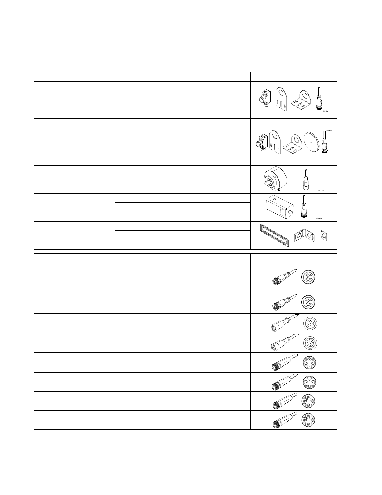
Kits
Kits Kits
Kits
List
Kits Kits
List List
Part
Part Part
24X446KIT,photoeye,
24X447KIT,photoeye,
24X448KIT,encoder,
17E020KIT,runup
24X607KIT,encoder
Description
Description Description
diffuse,18mm
polretref,18mm
1000PPR,
10mm
brackets
Contents
Contents Contents
128073-SENSOR,photoelectricdiffuse
128070-BRACKET,sensormount,angled
128071-BRACKET,sensormount,straight
128081-CABLE,M12,4-pin,5.0m
128072-SENSOR,photoelectric,polarized
128069-SENSOR,reector
128070-BRACKET,sensormount,angled
128071-BRACKET,sensormount,straight
128081-CABLE,M12,4-pin,5.0m
128074-ENCODER,incremental
128079-CABLE,M12,8-pin,10.0m
127787-REGULATOR,pressure,V2P
128081-CABLE,M12,4–pin,5.0m
_______-FITTINGS
17E017-BRACKET,90degree,encoder
17E018-BRACKET,encoder
17E037-BRACKET,mounting,encoder
Part
Part Part
24X449KIT,cable,M12,
24X453KIT,cable,M12,
24X454
24X455
24X456KIT,cable,M8,
24X457KIT,cable,M8,
24X458KIT,cable,M8,
24X459KIT,cable,M8,
Description
Description Description
4-pin,F-L,5m
4-pin,F-L,10m
KIT,cable,M12,
8-pin,F-L,5m
KIT,cable,M12,
8-pin,F-L,10m
3-pin,F-L,5m
3-pin,F-L,10m
4-pin,F-L,5m
4-pin,F-L,10m
Used
For
Used Used
For For
Standardsolenoidvalve(i.e.GS-35)
Run-upcontroller
TriggerswithM12connection(12mmnut)
Standardsolenoidvalve(i.e.GS-35)Run-up
controllerTriggerswithM12connection(12mm
nut)
Encoder
Encoder
Minisolenoidvalve(i.e.GM-100)
Minisolenoidvalve(i.e.GM-100)
TriggerswithM8connection(8mmnut)
TriggerswithM8connection(8mmnut)
44
334784A
Page 45

WiringDiagram
Wiring
Wiring Wiring
Ref.
Ref. Ref.
915U423
10127887
14
Diagram
Diagram Diagram
Part
Part Part
Description
Description Description
SWITCH,2P,25A
POWERSUPPLY,24
DC,6.3A,150W
HARNESS,ground
Qty.
Qty. Qty.
1
1
1
Ref.
Ref. Ref.
Part
Part Part
28
38
39
Description
Description Description
CONNECTOR,plug,3
position
TERMINAL,fork,#8
TERMINAL,fork,#4
Qty.
Qty. Qty.
1
2
1
334784A 45
Page 46

TechnicalData
Technical
Technical Technical
Description
Description Description
Gun
Outputs
Gun Gun
Outputs Outputs
Trigger
Trigger Trigger
Encoder
Encoder Encoder
Run
Run Run
PLC
PLC PLC
PLC
PLC PLC
PLC
PLC PLC
Integrated
Integrated Integrated
Program
Program Program
Beads
Beads Beads
Distance
Distance Distance
Time
Time Time
Enclosure
Enclosure Enclosure
Ambient
Ambient Ambient
Inputs
Inputs Inputs
Up
Control
Up Up
Control Control
Enable/Disable
Enable/Disable Enable/Disable
Program
Program Program
Alarm
Output
Alarm Alarm
Output Output
Power
Power Power
Storage
Storage Storage
Per
Output
Per Per
Output Output
Accuracy
Accuracy Accuracy
Accuracy
Accuracy Accuracy
Environmental
Environmental Environmental
Temperature
Temperature Temperature
Data
Data Data
Value
Value Value
8
4
2(PC-8eonly)Quadraturedifferentiallinedriver
2(PC-8eonly)I/P(4–20mA)orV/P(0–10V)
YES0–30VDC,min10Vtoassert
Select
Select Select
Bit
Bit Bit
Supply
Supply Supply
Rating
Rating Rating
32˚–120˚F,0˚–50˚C
4
YES0–250VAC(drycontactoutput)
YES
50
24
1mm,0.1in.
1ms
IP54Resistanttodustandsplashingwater
24VDC,1Aeach,6Amaxtotal
NPNorPNPorDryContact
Selectupto15uniqueprograms
Input:100–240VAC,50/60Hz
Output:24VDC,150W
Eachbeadcanbestitched,allowingmany
morethan24dots
Details
Details Details
46 334784A
Page 47

Notes
Notes
Notes Notes
334784A
47
Page 48

Graco
Graco Graco
GracowarrantsallequipmentreferencedinthisdocumentwhichismanufacturedbyGracoandbearingits
nametobefreefromdefectsinmaterialandworkmanshiponthedateofsaletotheoriginalpurchaserforuse.
Withtheexceptionofanyspecial,extended,orlimitedwarrantypublishedbyGraco,Gracowill,foraperiodof
twelvemonthsfromthedateofsale,repairorreplaceanypartoftheequipmentdeterminedbyGracotobe
defective.Thiswarrantyappliesonlywhentheequipmentisinstalled,operatedandmaintainedinaccordance
withGraco’swrittenrecommendations.
Thiswarrantydoesnotcover,andGracoshallnotbeliableforgeneralwearandtear,oranymalfunction,
damageorwearcausedbyfaultyinstallation,misapplication,abrasion,corrosion,inadequateorimproper
maintenance,negligence,accident,tampering,orsubstitutionofnon-Gracocomponentparts.NorshallGraco
beliableformalfunction,damageorwearcausedbytheincompatibilityofGracoequipmentwithstructures,
accessories,equipmentormaterialsnotsuppliedbyGraco,ortheimproperdesign,manufacture,installation,
operationormaintenanceofstructures,accessories,equipmentormaterialsnotsuppliedbyGraco.
Thiswarrantyisconditionedupontheprepaidreturnoftheequipmentclaimedtobedefectivetoanauthorized
Gracodistributorforvericationoftheclaimeddefect.Iftheclaimeddefectisveried,Gracowillrepairorreplace
freeofchargeanydefectiveparts.Theequipmentwillbereturnedtotheoriginalpurchasertransportation
prepaid.Ifinspectionoftheequipmentdoesnotdiscloseanydefectinmaterialorworkmanship,repairswillbe
madeatareasonablecharge,whichchargesmayincludethecostsofparts,labor,andtransportation.
THIS
WARRANTY
THIS THIS
WARRANTY WARRANTY
INCLUDING
INCLUDING INCLUDING
FOR
FOR FOR
A AAPARTICULAR PARTICULAR
Graco’ssoleobligationandbuyer’ssoleremedyforanybreachofwarrantyshallbeassetforthabove.The
buyeragreesthatnootherremedy(including,butnotlimitedto,incidentalorconsequentialdamagesforlost
prots,lostsales,injurytopersonorproperty,oranyotherincidentalorconsequentialloss)shallbeavailable.
Anyactionforbreachofwarrantymustbebroughtwithintwo(2)yearsofthedateofsale.
GRACO
GRACO GRACO
AND
FITNESS
AND AND
FITNESS FITNESS
MATERIALS
MATERIALS MATERIALS
manufacturedbyGraco(suchaselectricmotors,switches,hose,etc.),aresubjecttothewarranty,ifany,of
theirmanufacturer.Gracowillprovidepurchaserwithreasonableassistanceinmakinganyclaimforbreachof
thesewarranties.
InnoeventwillGracobeliableforindirect,incidental,specialorconsequentialdamagesresultingfromGraco
supplyingequipmenthereunder,orthefurnishing,performance,oruseofanyproductsorothergoodssold
hereto,whetherduetoabreachofcontract,breachofwarranty,thenegligenceofGraco,orotherwise.
FORGRACOCANADACUSTOMERS
ThePartiesacknowledgethattheyhaverequiredthatthepresentdocument,aswellasalldocuments,notices
andlegalproceedingsenteredinto,givenorinstitutedpursuantheretoorrelatingdirectlyorindirectlyhereto,be
drawnupinEnglish.Lespartiesreconnaissentavoirconvenuquelarédactionduprésentedocumentseraen
Anglais,ainsiquetousdocuments,avisetprocéduresjudiciairesexécutés,donnésouintentés,àlasuitedeou
enrapport,directementouindirectement,aveclesprocéduresconcernées.
Standard
Standard Standard
EXCLUSIVE,
IS ISISEXCLUSIVE, EXCLUSIVE,
BUT
NOT
BUT BUT
PARTICULAR
MAKES
MAKES MAKES
FOR
FOR FOR
OR
OR OR
LIMITED
NOT NOT
LIMITED LIMITED
PURPOSE.
PURPOSE. PURPOSE.
NO
WARRANTY,
NO NO
WARRANTY, WARRANTY,
PARTICULAR
A AAPARTICULAR PARTICULAR
COMPONENTS
COMPONENTS COMPONENTS
Warranty
Warranty Warranty
AND
IS
IN
LIEU
OF
ANY
AND AND
IS IS
IN IN
LIEU LIEU
TO
WARRANTY
TO TO
WARRANTY WARRANTY
AND
DISCLAIMS
AND AND
DISCLAIMS DISCLAIMS
PURPOSE,
PURPOSE, PURPOSE,
SOLD
BUT
SOLD SOLD
BUT BUT
OF OF
OF
MERCHANTABILITY
OF OF
MERCHANTABILITY MERCHANTABILITY
ALL
ALL ALL
IN
CONNECTION
IN IN
NOT
NOT NOT
CONNECTION CONNECTION
MANUFACTURED
MANUFACTURED MANUFACTURED
OTHER
ANY ANY
OTHER OTHER
IMPLIED
IMPLIED IMPLIED
WARRANTIES,
WARRANTIES, WARRANTIES,
OR
OR OR
WARRANTIES
WARRANTIES WARRANTIES
WITH
ACCESSORIES,
WITH WITH
ACCESSORIES, ACCESSORIES,
BY
GRACO.
BY BY
GRACO. GRACO.
EXPRESS
EXPRESS EXPRESS
WARRANTY
WARRANTY WARRANTY
OF
MERCHANTABILITY
OF OF
MERCHANTABILITY MERCHANTABILITY
Theseitemssold,butnot
OR
IMPLIED,
OR OR
OF
OF OF
EQUIPMENT,
EQUIPMENT, EQUIPMENT,
IMPLIED, IMPLIED,
FITNESS
FITNESS FITNESS
Graco
Graco Graco
ForthelatestinformationaboutGracoproducts,visitwww.graco.com.
Forpatentinformation,seewww.graco.com/patents.
To
To To
Phone:
Phone: Phone:
Allwrittenandvisualdatacontainedinthisdocumentreectsthelatestproductinformationavailableatthetimeofpublication.
Information
Information Information
place
an
place place
an an
612-623-6921or ororToll Toll
order,
order, order,
contactyourGracoDistributororcalltoidentifythenearestdistributor.
Toll
Free:
Free: Free:
1-800-328-0211Fax: Fax:
Gracoreservestherighttomakechangesatanytimewithoutnotice.
OriginalInstructions.ThismanualcontainsEnglish.MM334784 334784
Graco
Graco Graco
International
International International
GRACO
GRACO GRACO
INC.
AND
INC. INC.
Copyright
Copyright Copyright
SUBSIDIARIES
AND AND
SUBSIDIARIES SUBSIDIARIES
2014,
Graco
2014, 2014,
Inc.
Graco Graco
Inc. Inc.
Ofces:
Ofces: Ofces:
• ••P.O. P.O.
All
Graco
All All
Graco Graco
RevisionA,January2015
Fax:
Headquarters:
Headquarters: Headquarters:
Belgium,China,Japan,Korea
P.O.
BOX
BOX BOX
manufacturing
manufacturing manufacturing
www.graco.com
612-378-3505
334784
Minneapolis
1441
MINNEAPOLIS
1441 1441
• ••MINNEAPOLIS MINNEAPOLIS
locations
locations locations
MN
MN MN
are
registered
are are
registered registered
55440-1441
55440-1441 55440-1441
ISO
to totoISO ISO
USA
• ••USA USA
9001.
9001. 9001.
 Loading...