

Page 1
Repair Kit
334201A
Air Controls
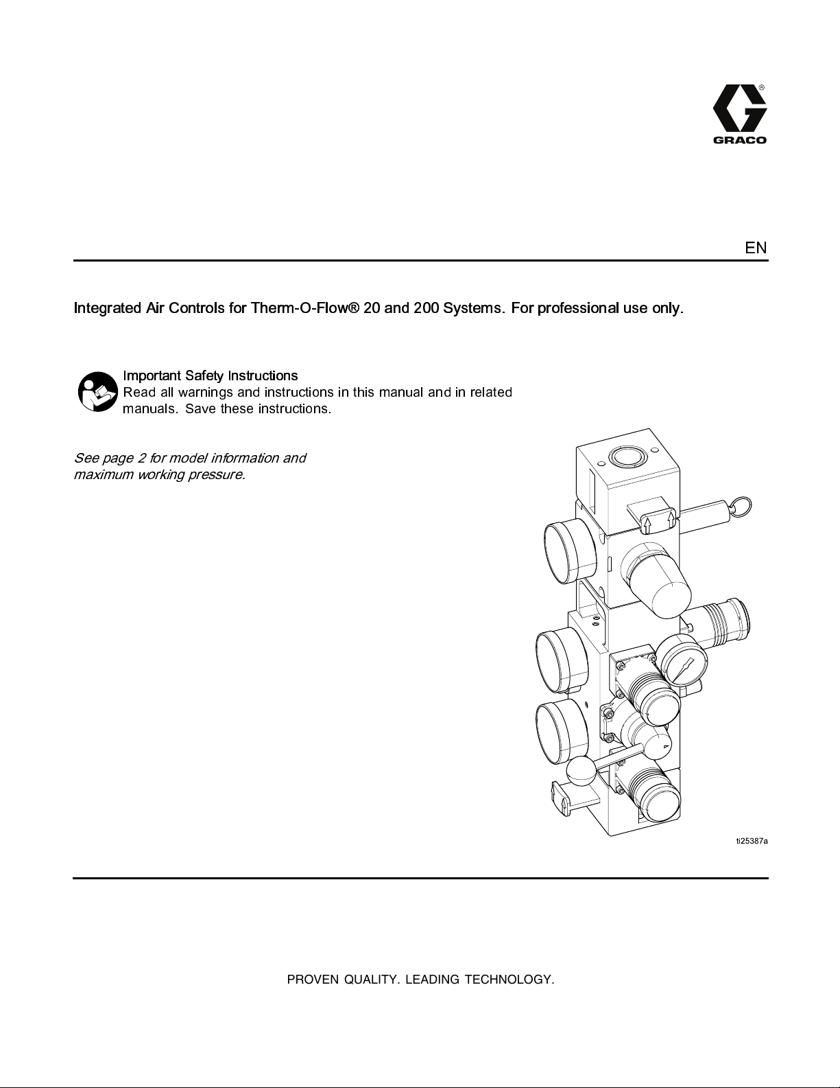
Integrated Air Controls for Therm-O-Flow® 20 and 200 Systems. For professional use only.
Important Safety Instructions
Read all warnings and instructions in this manual and in related
manuals. Save these instructions.
See page 2 for model information and
maximum working pressure.
EN
PROVEN QUALITY. LEADING TECHNOLOGY.
Page 2
Models
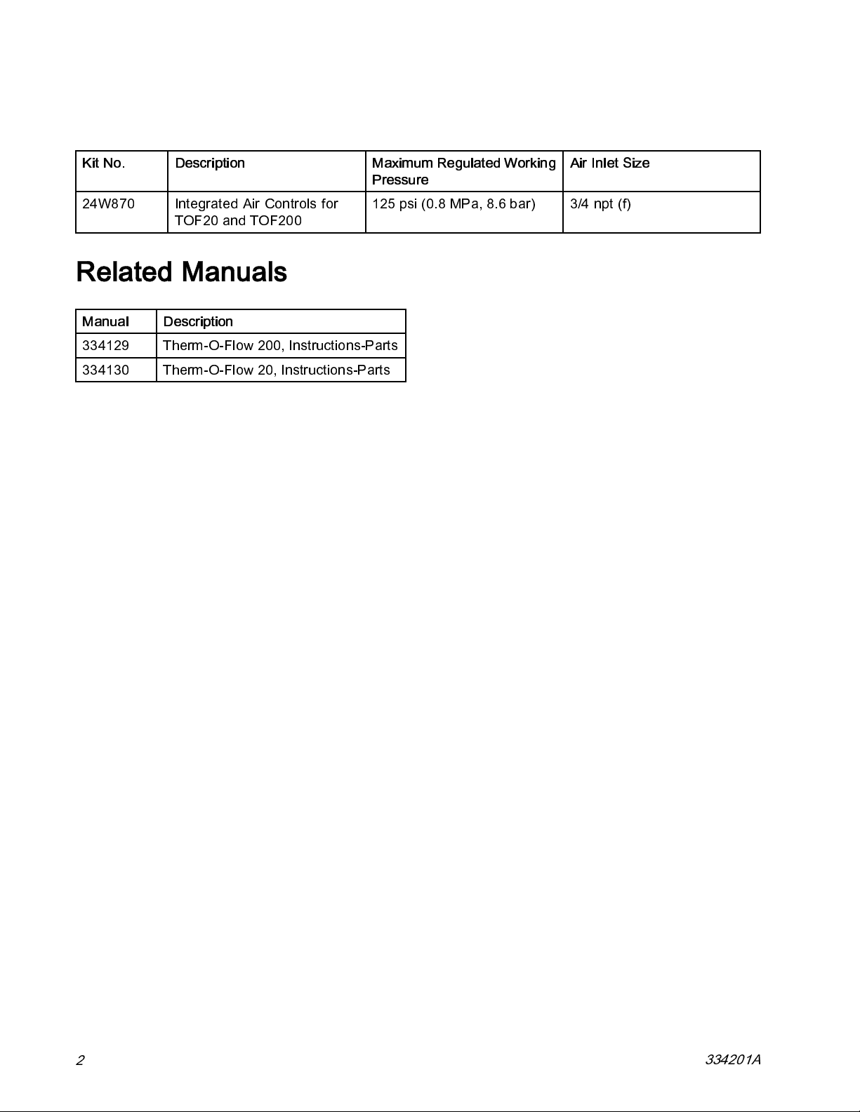
Kit No. Description Maximum Regulated Working
Pressure
24W870
Integrated Air Controls for
TOF20 and TOF200
125 psi (0.8 MPa, 8.6 bar) 3/4 npt (f)
Related Manuals
Manual Description
334129
334130 Therm-O-Flow 20, Instructions-Parts
Therm-O-Flow 200, Instructions-Parts
Air Inlet Size
2
334201A
Page 3

Repair
Repair
Remove
1. Relieve pressure. See system manual for
instructions.
2. Disconnect all hoses and tubing from air control.
3. Remove 4 screws and washers.
3. Remove spring (5c), valve plate (5d), and o-ring
(5b).
Note
Note the orientation of the director valve
plate when you remove it. The opening
should be on the opposite side (left) of
the lever.
4. Remove and discard pin (5g) and four valve
seats (5e) with o-rings (5f).
5. Insert new valve seats (5e) with o-rings (5f) and
new pin (5g).
6. Insert new director valve plate (5d, see Note
above) spring (5c), and o-rin g (5b).
7. Attach new director valve with screws (5a).
Tighten screws until snug.
Replace Director Valve
1. Relieve pressure. See system manual for
instructions.
2. Remove screws (5a) and take off director valve.
334201A 3
Figure 1
Page 4
Repair
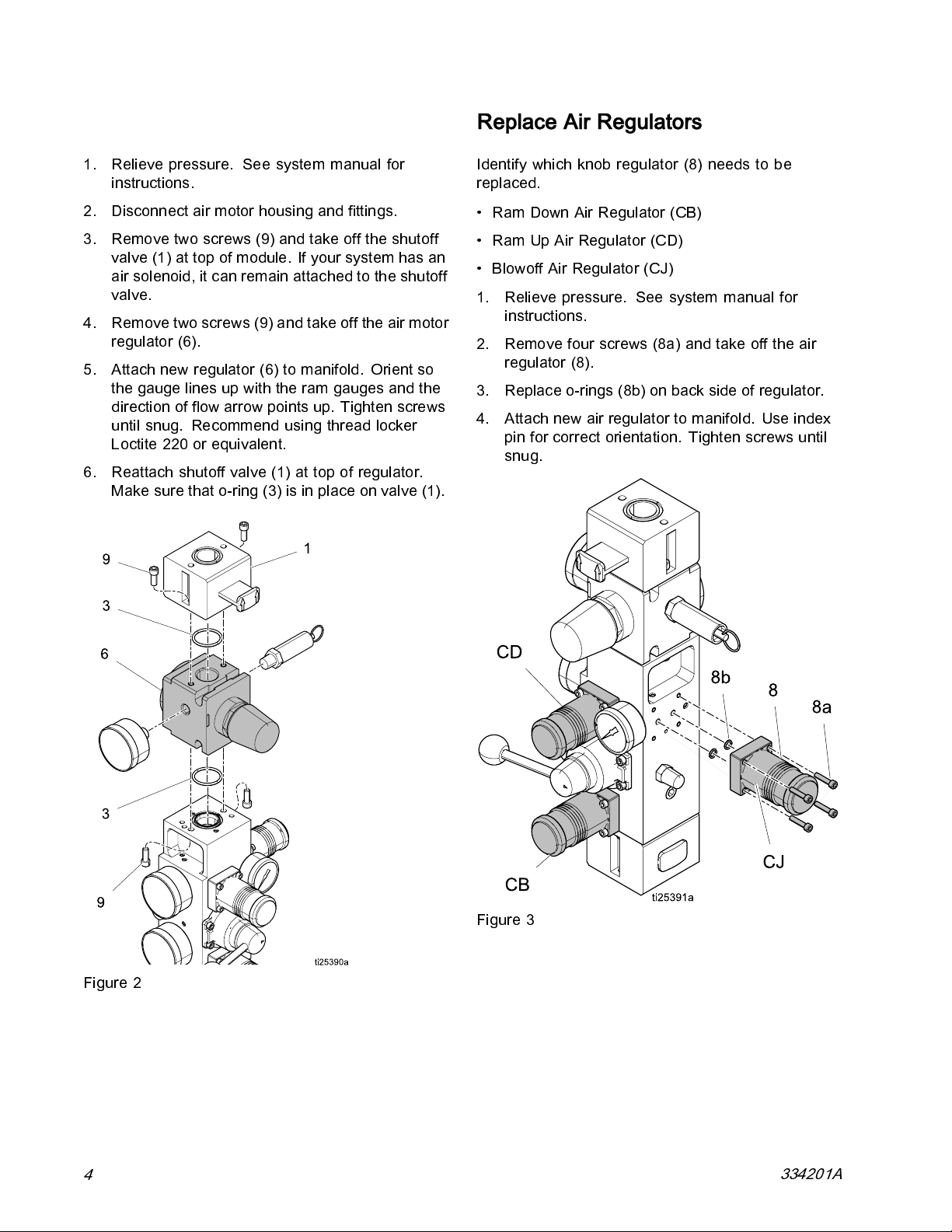
Replace Air Motor Regulator
1. Relieve pressure. See system manual for
instructions.
2. Disconnect air motor housing and fittings.
3. Remove two screws (9) and take off the shutoff
valve (1) at top of module. If your system has an
air solenoid, it can remain attached to the shutoff
valve.
4. Removetwoscrews(9)andtakeofftheairmotor
regulator (6).
5. Attach new regulat or (6) to manifold. Orie nt so
the gauge lines up with the ram gauges and the
direction of flow arrow points up. Tighten screws
until snug. Recommend using thread locker
Loctite 220 or equivalent.
6. Reattach shutoff valve (1) at top of regulator.
Make sure that o-ring (3) is in place on valve (1).
Replace Air Regulators
Identify which knob regulator (8) needs to be
replaced.
• Ram Down Air Regulator (CB)
• Ram Up Air Regulator (CD)
• Blowoff Air Regulator (CJ)
1. Relieve pressure. See system manual for
instructions.
2. Remove four screws (8a) and take off the air
regulator (8).
3. Replace o-rings (8b) on back side of regulator.
4. Attach new air regulator to manifold. Use index
pin for correct orientation. Tighten screws until
snug.
Figure 2
4
Figure 3
334201A
Page 5

Parts
24W870 Air Control
Parts
334201A 5
Page 6
Graco Information
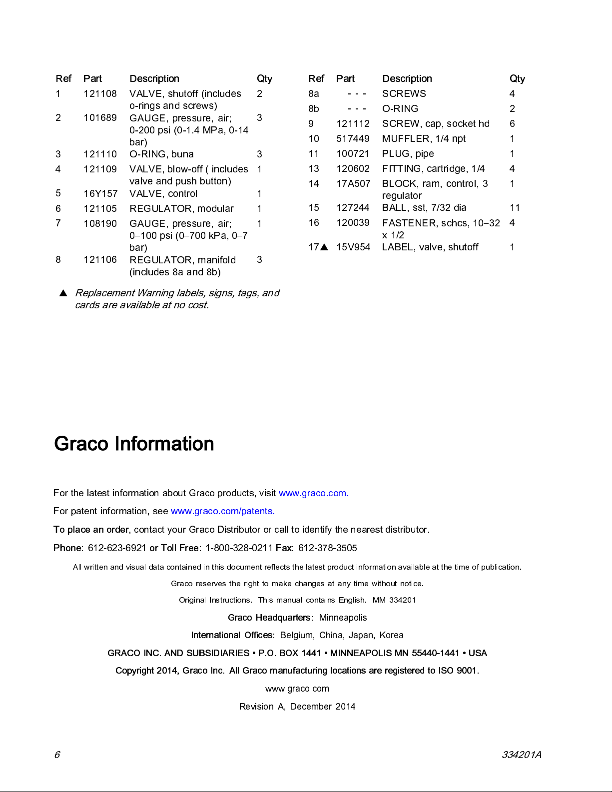
Part Description
Ref
1 121108
VALVE, shutoff (includ es
o-rings and screws)
2 101689
GAUGE, pressure, air;
0-200 psi (0-1.4 MPa, 0-14
bar)
3 121110
4 121109
O-RING, buna
VALVE, blow-off ( includes
valve and push button)
5
16Y157 VALVE, control 1
6 121105
7
108190
REGULATOR, m od ula r
GAUGE, pressure, air;
0–100 psi (0–700 kPa, 0–7
bar)
8 121106
REGULATOR, man ifo ld
(includes 8a and 8b)
▲
Replacement Warning labels, signs, tags, and
cards are available at no cost.
Qty
2
3
3
1
1
1
3
Part Description
Ref
8a
8b
9121112
---
---
SCREWS
O-RING
SCREW, cap, socket hd
Qty
4
2
6
10 517449 MUFFLER, 1/4 npt 1
11 100721
13 120602
14 17A507
PLUG, pipe
FITTING, cartridge, 1/4
BLOCK, ram, control, 3
1
4
1
regulator
15 127244 BALL, sst, 7/32 dia 11
16 120039
FASTENER, schcs, 10–32
4
x1/2
17
▲
15V954
LABEL, valve, shutoff
1
Graco Information
For the latest information about Graco products, visit www.graco.com.
For patent information, see www.graco.com/patents.
To place an order,
Phone:
612-623-6921
All written and visual data contained in this document reflects the latest product information available at the time of publication.
contact your Graco Distributor or call to identify the nearest distributor.
or Toll Free:
Graco reserves the right to make changes at any time without notice.
GRACO INC. AND SUBSIDIARIES • P.O. BOX 1441 • MINNEAPOLIS MN 55440-1441 • USA
Copyright 2014, Graco Inc. All Graco manufacturing locations are registered to ISO 9001.
1-800-328-0211
Original Instructions. This manual contains English. MM 334201
Graco Headquarters:
International Offices:
Revision A, December 2014
Fax:
612-378-3505
Minneapolis
Belgium, China, Japan, Korea
www.graco.com
6 334201A
 Loading...