

Page 1
Instructions - Parts
Modbus TCP
334183A
Gateway Module
For use with systems based on Graco Control Architecture to provide Modbus TCP
communications capabilities.
Important Safety Instructions
Read all warnings and instructions in the system
operation manual. Save these instructions.
EN
RECOGNIZED
COMPONENT
R
T
E
T
N
I
L
I
S
E
C
T
4003764
E
K
Conforms to
UL STD 508
D
US
Certified to CAN/CSA STD C22.2 No. 14
Page 2

Models
Contents
Models ...................................2
Component Identification ....................3
Overview .................................. 4
Installation ................................4
Setup.....................................5
Troubleshooting ........................... 10
Parts ....................................11
TechnicalData ............................11
Graco Standard Warranty ................... 12
GracoInformation ........................12
Models
Communications
Gateway Module Part No. Fieldbus
24W462 Modbus TCP
To order replacement parts, see Parts on page 9.
To order installation kits for a system based on Graco
Control Architecture, see the system operation manual.
2 334183A
Page 3
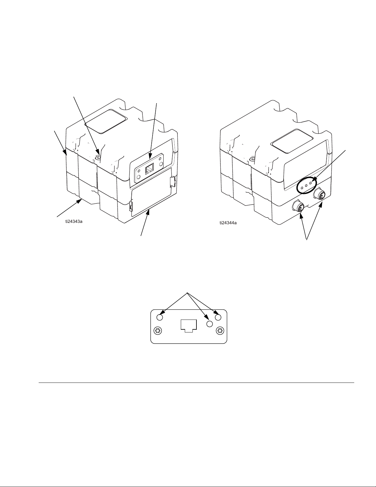
Component Identification
Front Back
D
C
A
Component Identification
F
B
E
Fieldbus Connector (C)
FIG.1:
Key:
A Communications Gateway Module
B Base
C Fieldbus Connector
D Module Connection Screws
E Access Cover
F Module Status LEDs
G Fieldbus Status LEDs (see descriptions on page 6)
H CAN Connectors
H
Modbus TCP
G
TI11814A
334183A 3
Page 4

Overview
Overview
Module Description
The Modbus TCP (MBTCP) Gateway Module provides a
control link between a Modbus TCP fieldbus and a system that uses Graco Control Architecture (GCA). This
link provides the means for remote monitoring and control by an external automation system.
Data provided by the MBTCP Gateway Module to the
fieldbus depends on the GCA-based system. Mapping
of Modbus registers is loaded by the host GCA system
and varies by system.
Data Exchange
Data is available by block transfer or by explicit access
to individual attributes as defined by the fieldbus specification.
Module Status LED Signals
Signal Description
Module Requirements
Power Supply
The MBTCP Gateway Module requires a 12-30 VDC @
0.2 A power supply. Refer to the system manual for system level power supply guidelines.
Environment Conditions
Refer to the system manual for guidelines regarding
environment conditions for the MBTCP module.
Green on The system is powered up.
Yellow Internal communication is in prog-
ress.
Red
Solid
Red Flashing The red LED (F) will flash a code,
3 flashes The host device of the mapped
4 flashes No valid mapping is set by the
5 flashes MBTCP is not connected or the
NOTE:
If you get a “No Valid Map” error, disable and re-enable
your gateway from the host device.
MBTCP hardware failure
pause, then repeat. See MBTCP
Module Errors on page 7 for
details.
property is not responding.
host.
system has an invalid network
configuration.
4 334183A
Page 5

Installation
Installation
The MBTCP Gateway Module is available for use with
all GCA-based systems that have a compatible design.
Each MBTCP module requires the following to operate
in a system:
• Mounting hardware
• Compatible GCA system
Install the MBTCP module as explained in the system
operation manual or in the installation kit manual.
If the MBTCP is offered only as an accessory for your
system, see Accessories in the system operation manual for available MBTCP kits.
Connect Cables
Connect cables as explained in the system operation
manual.
NOTICE
Route cables to avoid interference with moving
parts.
Rotary Switch
If your system has only one MBTCP module, keep the
rotary switch (S) at its default position of 0.
If the system has multiple MBTCP modules, use a
unique value (position) for each module. Remove the
access cover (E) to set the rotary switch (S) for each
module.
S
E
FIG.2
334183A 5
Page 6

Installation
Fieldbus Connectors
Ref.
1
2
3
4
Network Status LED
LED State Description
Off No power or no IP address
Green Connection established. Module is in the Process
Flashing Green Waiting for connection
Red Duplicate IP address or FATAL event
Flashing Red Process Active timeout
Network Status LED
Module Status LED
Item
Link/Activity
Ethernet Interface
Active state or the Idle state.
1
2
4
3
Module Status LED
LED State Description
Off No power
Green Normal operation
Red Major fault. The module is in the state
of EXCEPTION (or FATAL event).
Red Flashing Minor fault in diagnostic object or IP
conflict
Link/Activity LED
LED State Description
Off No Link, no communication present
Green Link established, no communication present
Flashing Green Link established, communication present
Ethernet Interface
The Ethernet interface supports 10/100 Mbit, full or half duplex operation.
6 334183A
Page 7

Troubleshooting
Troubleshooting
MBTCP Module Errors
Module errors are triggered by overall system operation. The module status LED blinks red at a frequency of 1 Hz.
The red LED (F) will flash a code, pause, then repeat.
Module Status LED Signal Diagnosis Solution
3 red flashes The host of the mapped property is
not responding.
4 red flashes The host device (ADM) has not initi-
ated property mapping.
5 red flashes The MBTCP module is not con-
nected.
The system has an invalid network
Configuration.
Check whether all system devices
are powered on.
Check cabling between all system
devices.
Disable and then re-enable the gateway module from the host device
(ADM).
Verify that the MBTCP module is connected.
Verify the proper network Confiugration.
334183A 7
Page 8

Troubleshooting
Modbus Errors
Modbus errors are typical protocol errors defined by fieldbus specification. The fieldbus error code shown is returned
to the PLC when the error condition occurs.
Code Name Cause Solution
1 Illegal Function Request function is not supported. Use supported Modbus functions:
• Read Holding Register
• Write Holding Register
• Write Multiple Holding Registers
2 Illegal Data Address Exceeded maximum register count
of 121 registers.
No valid property mapped to the
requested Modbus register.
Write Holding Register(s) returns
set property error.
3 Illegal Data Value
4 Slave Device Fail Not implemented.
5 Acknowledge Not implemented.
6 Slave Device Busy Not implemented.
8 Memory Parity Error Not implemented.
10 Gatweay Path Unavailable Not implemented.
11 Gateway Target Fail An active system error exists. Refer to system errors table.
255 Unspecified
Request 121 or fewer registers at a time.
Verify that the device has valid mapping.
See MBTCP Modbus Error for 4 red
flashes.
Verify that the end device is online.
Not implemented.
8 334183A
Page 9

Parts
Modbus TCP Gateway Module
D
Parts
Parts
Ref Part No. Description Qty.
A 24W777 MODULE, Gateway, Modbus TCP 1
B 289697 Base 1
D 114135 SCREW, mounting, module connec-
A
E 277674 COVER, access 1
tion
2
B
E
Technical Data
Category Data
Power requirements 12-30 VDC @ 0.2 A
Weight 12.8 oz.
Dimensions 4.3 in. x 3.8 in. x 3.8 in.
334183A 9
Page 10

Graco Standard Warranty
Graco warrants all equipment referenced in this document which is manufactured by Graco and bearing its name to be free from defects in
material and workmanship on the date of sale to the original purchaser for use. With the exception of any special, extended, or limited warranty
published by Graco, Graco will, for a period of twelve months from the date of sale, repair or replace any part of the equipment determined by
Graco to be defective. This warranty applies only when the equipment is installed, operated and maintained in accordance with Graco’s written
recommendations.
This warranty does not cover, and Graco shall not be liable for general wear and tear, or any malfunction, damage or wear caused by faulty
installation, misapplication, abrasion, corrosion, inadequate or improper maintenance, negligence, accident, tampering, or substitution of
non-Graco component parts. Nor shall Graco be liable for malfunction, damage or wear caused by the incompatibility of Graco equipment with
structures, accessories, equipment or materials not supplied by Graco, or the improper design, manufacture, installation, operation or
maintenance of structures, accessories, equipment or materials not supplied by Graco.
This warranty is conditioned upon the prepaid return of the equipment claimed to be defective to an authorized Graco distributor for verification of
the claimed defect. If the claimed defect is verified, Graco will repair or replace free of charge any defective parts. The equipment will be returned
to the original purchaser transportation prepaid. If inspection of the equipment does not disclose any defect in material or workmanship, repairs will
be made at a reasonable charge, which charges may include the costs of par ts, labor, and transportation.
THIS WARRANTY IS EXCLUSIVE, AND IS IN LIEU OF ANY OTHER WARRANTIES, EXPRESS OR IMPLIED, INCLUDING BUT NOT LIMITED
TO WARRANTY OF MERCHANTABILITY OR WARRANTY OF FITNESS FOR A PARTICULAR PURPOSE.
Graco’s sole obligation and buyer’s sole remedy for any breach of warranty shall be as set forth above. The buyer agrees that no other remedy
(including, but not limited to, incidental or consequential damages for lost profits, lost sales, injury to person or property, or any other incidental or
consequential loss) shall be available. Any action for breach of warranty must be brought within two (2) years of the date of sale.
GRACO MAKES NO WARRANTY, AND DISCLAIMS ALL IMPLIED WARRANTIES OF MERCHANTABILITY AND FITNESS FOR A
PARTICULAR PURPOSE, IN CONNECTION WITH ACCESSORIES, EQUIPMENT, MATERIALS OR COMPONENTS SOLD BUT NOT
MANUFACTURED BY GRACO. These items sold, but not manufactured by Graco (such as electric motors, switches, hose, etc.), are subject to
the warranty, if any, of their manufacturer. Graco will provide purchaser with reasonable assistance in making any claim for breach of these
warranties.
In no event will Graco be liable for indirect, incidental, special or consequential damages resulting from Graco supplying equipment hereunder, or
the furnishing, performance, or use of any products or other goods sold hereto, whether due to a breach of contract, breach of warranty, the
negligence of Graco, or otherwise.
FOR GRACO CANADA CUSTOMERS
The Parties acknowledge that they have required that the present document, as well as all documents, notices and legal proceedings entered into,
given or instituted pursuant hereto or relating directly or indirectly hereto, be drawn up in English. Les parties reconnaissent avoir convenu que la
rédaction du présente document sera en Anglais, ainsi que tous documents, avis et procédures judiciaires exécutés, donnés ou intentés, à la suite
de ou en rapport, directement ou indirectement, avec les procédures concernées.
Graco Information
TO PLACE AN ORDER, contact your Graco distributor or call to identify the nearest distributor.
Phone: 612-623-6921 or Toll Free: 1-800-328-0211 Fax: 612-378-3505
All written and visual data contained in this document reflects the latest product information available at the time of publication.
GRACO INC. AND SUBSIDIARIES • P.O. BOX 1441 • MINNEAPOLIS MN 55440-1441 • USA
Copyright 2014, Graco Inc. All Graco manufacturing locations are registered to ISO 9001.
Graco reserves the right to make changes at any time without notice.
2ULJLQDOLQVWUXFWLRQV This manual contains English. MM 334183
Graco Headquarters: Minneapolis
International Offices: Belgium, China, Japan, Korea
www.graco.com
 Loading...