

Page 1
Instructions
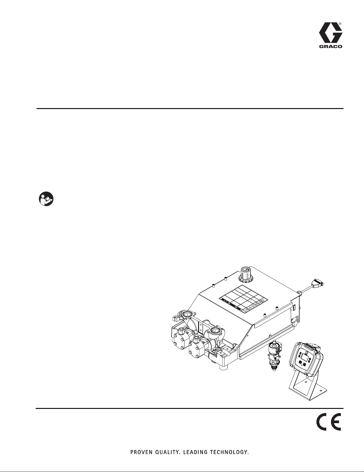
PR70e
™
334135B
Compact Benchtop Meter, Mix and Dispense System
Use for accurate metering, mixing and dispensing of two-component sealants and
adhesives in fixed ratios. Not for use with isocyanate catalyzed materials. For professional
use only.
Not approved for use in explosive atmospheres or hazardous locations.
Refer to Models, page 3, for maximum working pressures.
Important Safety Instructions
Read all warnings and instructions in this
manual. Save these instructions.
EN
Page 2

Contents
Models . . . . . . . . . . . . . . . . . . . . . . . . . . . . . . . . . . . 3
Related Manuals . . . . . . . . . . . . . . . . . . . . . . . . . . . 3
Warnings . . . . . . . . . . . . . . . . . . . . . . . . . . . . . . . . . 4
Component Identification . . . . . . . . . . . . . . . . . . . . 6
Machine . . . . . . . . . . . . . . . . . . . . . . . . . . . . . . . 6
Local Control Module (LCM) . . . . . . . . . . . . . . . . 7
LCM Screen Navigation . . . . . . . . . . . . . . . . . . . 8
Recommended Parts . . . . . . . . . . . . . . . . . . . . . . . 10
Dispense Valve . . . . . . . . . . . . . . . . . . . . . . . . . 10
Mixers . . . . . . . . . . . . . . . . . . . . . . . . . . . . . . . . 12
Applicator Mounting . . . . . . . . . . . . . . . . . . . . . 14
Air Filter and Ball Valve, 24R707 . . . . . . . . . . . 15
High Temperature Grease, 115982 . . . . . . . . . . 15
Footswitch, 255244 . . . . . . . . . . . . . . . . . . . . . . 15
Tanks . . . . . . . . . . . . . . . . . . . . . . . . . . . . . . . . . 16
Hose Packages . . . . . . . . . . . . . . . . . . . . . . . . . 18
Piston Package . . . . . . . . . . . . . . . . . . . . . . . . . 20
Pump Tube Combination Information . . . . . . . . . 22
Installation . . . . . . . . . . . . . . . . . . . . . . . . . . . . . . . 23
Grounding . . . . . . . . . . . . . . . . . . . . . . . . . . . . . 23
Machine Installation . . . . . . . . . . . . . . . . . . . . . 23
Setup . . . . . . . . . . . . . . . . . . . . . . . . . . . . . . . . . . . . 26
Piston Position Calibration . . . . . . . . . . . . . . . . 26
Prime the Dispense Head . . . . . . . . . . . . . . . . . 28
Phasing Adjustment . . . . . . . . . . . . . . . . . . . . . 29
Adjust Dispense Valve Snuff Back . . . . . . . . . . 31
Adjust Open Dispense Valve (ODV) Timing . . . 32
Operation . . . . . . . . . . . . . . . . . . . . . . . . . . . . . . . . 33
Startup . . . . . . . . . . . . . . . . . . . . . . . . . . . . . . . 33
Pressure Relief
Procedure . . . . . . . . . . . . . . . . . . . . . . . . . . 33
Shutdown . . . . . . . . . . . . . . . . . . . . . . . . . . . . . 34
Maintenance . . . . . . . . . . . . . . . . . . . . . . . . . . . . . . 35
Schedule . . . . . . . . . . . . . . . . . . . . . . . . . . . . . . 35
Clean the Pump Shafts . . . . . . . . . . . . . . . . . . . 35
Disassemble and Clean the Dispense Head . . . 35
Install Upgrade Token . . . . . . . . . . . . . . . . . . . . 36
Troubleshooting . . . . . . . . . . . . . . . . . . . . . . . . . . . 37
LCM Error Codes . . . . . . . . . . . . . . . . . . . . . . . 39
Repair . . . . . . . . . . . . . . . . . . . . . . . . . . . . . . . . . . . 40
HydraCheck Kit Installation, 24W336 . . . . . . . . 40
Air Cylinder Rebuild Instructions . . . . . . . . . . . . 42
Rear Pump Rebuild Instructions . . . . . . . . . . . . 44
Piston/Cylinder Replacement Kit Installation . . 46
Check Valve Rebuild Kit Installation . . . . . . . . . 47
Parts . . . . . . . . . . . . . . . . . . . . . . . . . . . . . . . . . . . . 48
Fixed Ratio Base . . . . . . . . . . . . . . . . . . . . . . . . 48
Pump Sub-Assembly, 24S053 . . . . . . . . . . . . . . 50
Fixed Ratio Drive Block Assembly, LC0107 . . . . 52
Air Cylinder, 24V933 and 24V934 . . . . . . . . . . . 53
Fixed Ratio Frame Sub-Assembly, LC0290 . . . . 54
Schematics . . . . . . . . . . . . . . . . . . . . . . . . . . . . . . . 56
Electrical Schematics . . . . . . . . . . . . . . . . . . . . 56
Pneumatic Schematic . . . . . . . . . . . . . . . . . . . . 58
Appendix A - LCM Icon Overview . . . . . . . . . . . . . 60
Appendix B - LCM Run Screen Overview . . . . . . 62
Appendix C - LCM Setup Screen Overview . . . . . 64
Kits . . . . . . . . . . . . . . . . . . . . . . . . . . . . . . . . . . . . . 65
Nylon and UHMW Piston Replacement Kits . . . 65
Recommended Spare Parts . . . . . . . . . . . . . . . 66
Dimensions . . . . . . . . . . . . . . . . . . . . . . . . . . . . . . . 67
Technical Data . . . . . . . . . . . . . . . . . . . . . . . . . . . . 69
Graco Standard Warranty . . . . . . . . . . . . . . . . . . . 70
Graco Information . . . . . . . . . . . . . . . . . . . . . . . . . 70
2 334135B
Page 3
Models
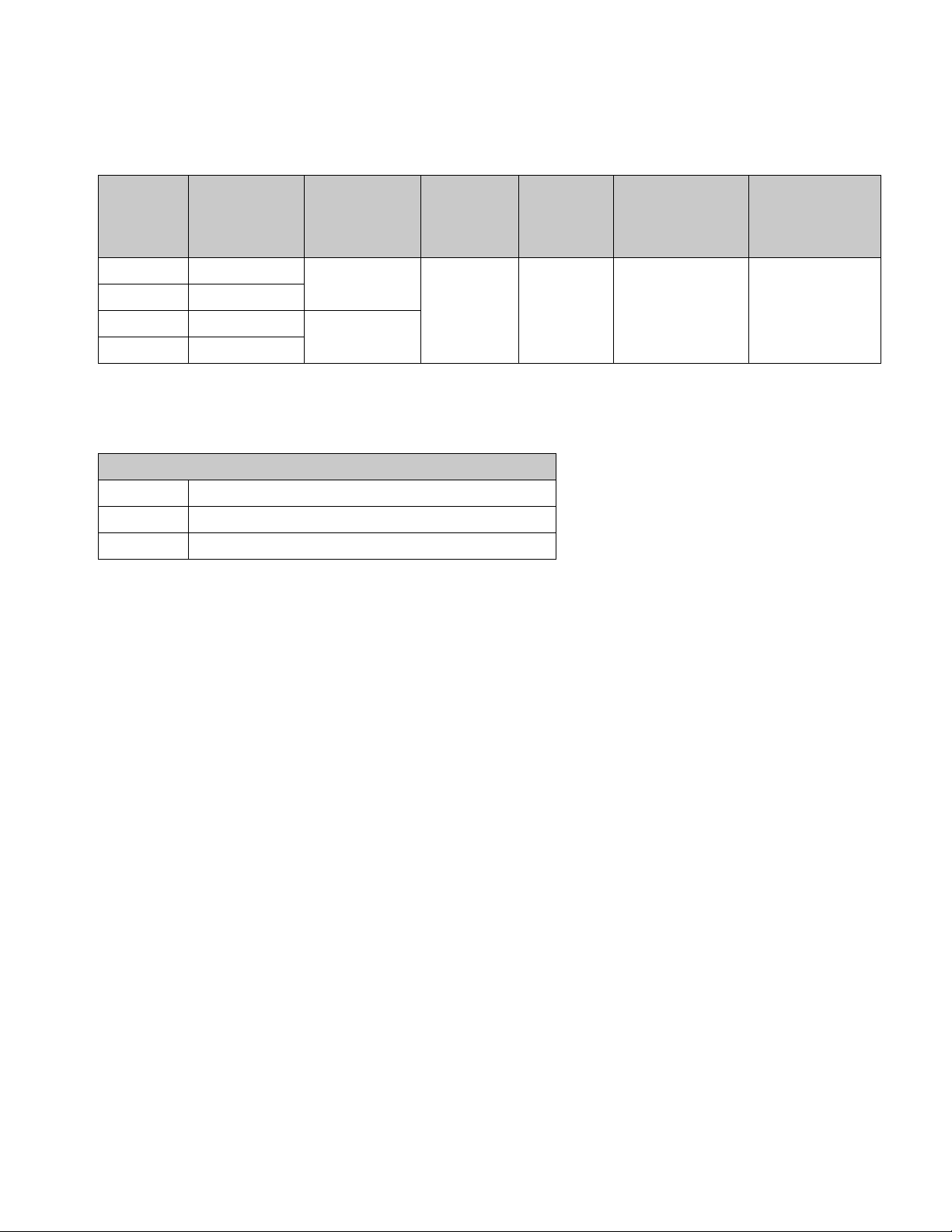
Models
System MD2 Valve
Ratio
24S054 1:1
24S055 10:1
24S056 1:1
24S057 10:1
Air Motor
in. (cm)
3 (7.6)
4.5 (11.4)
Required
Line
Volt ag e
100-240 V
50/60 Hz,
1 phase -
50 Watts
Related Manuals
MD2 Dispense Valve Manual
Part Description
312185 MD2 Valve, Instructions
312394 PR70 and PR70v Feed Systems, Instructions-Parts
Machine
Operation
Volt ag e
24 VDC 3000 (21, 207) 100 (0.7, 7)
Maximum
Working
Pressure
psi (MPa, bar)
Maximum
Air Inlet
Pressure
psi (MPa, bar)
334135B 3
Page 4
Warnings
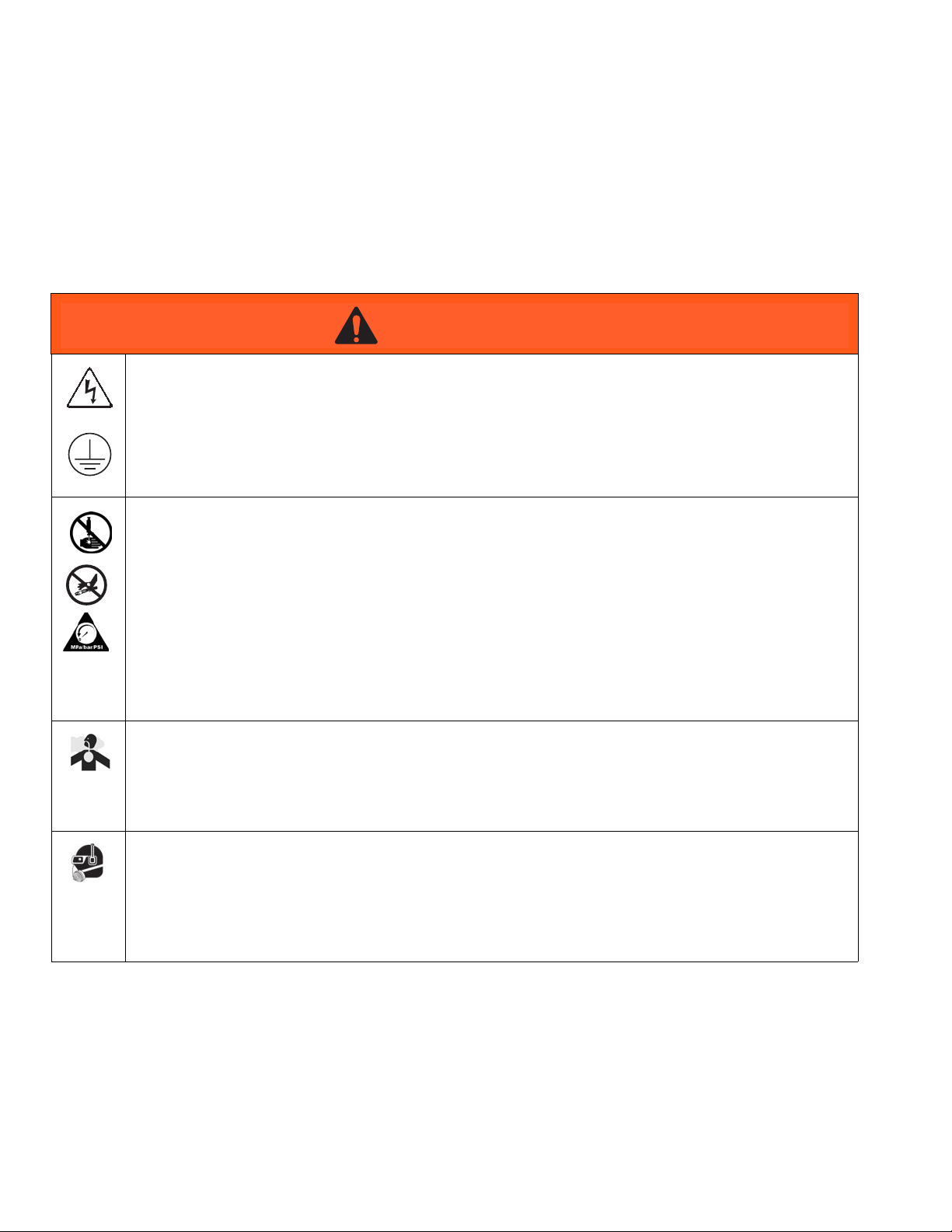
Warnings
The following warnings are for the setup, use, grounding, maintenance, and repair of this equipment. The exclamation point symbol alerts you to a general warning and the hazard symbols refer to procedure-specific risks. When
these symbols appear in the body of this manual or on warning labels, refer back to these Warnings. Product-specific
hazard symbols and warnings not covered in this section may appear throughout the body of this manual where
applicable.
WARNING
WARNINGWARNINGWARNING
ELECTRIC SHOCK HAZARD
This equipment must be grounded. Improper grounding, setup, or usage of the system can cause electric
shock.
• Turn off and disconnect power cord before servicing equipment.
• Connect only to grounded electrical outlets.
• Ensure ground prongs are intact on power and extension cords.
• Do not expose to rain. Store indoors.
SKIN INJECTION HAZARD
High-pressure fluid from dispensing device, hose leaks, or ruptured components will pierce skin. This
may look like just a cut, but it is a serious injury that can result in amputation. Get immediate surgical
treatment.
• Do not point dispensing device at anyone or at any part of the body.
• Do not put your hand over the fluid outlet.
• Do not stop or deflect leaks with your hand, body, glove, or rag.
• Follow the Pressure Relief Procedure when you stop dispensing and before cleaning, checking, or
servicing equipment.
• Tighten all fluid connections before operating the equipment.
• Check hoses and couplings daily. Replace worn or damaged parts immediately.
TOXIC FLUID OR FUMES HAZARD
Toxic fluids or fumes can cause serious injury or death if splashed in the eyes or on skin, inhaled, or
swallowed.
• Read MSDSs to know the specific hazards of the fluids you are using.
• Store hazardous fluid in approved containers, and dispose of it according to applicable guidelines.
PERSONAL PROTECTIVE EQUIPMENT
Wear appropriate protective equipment when in the work area to help prevent serious injury, including
eye injury, hearing loss, inhalation of toxic fumes, and burns. This protective equipment includes but is
not limited to:
• Protective eyewear, and hearing protection.
• Respirators, protective clothing, and gloves as recommended by the fluid and solvent manufacturer.
4 334135B
Page 5

Warnings
WARNING
WARNINGWARNINGWARNING
FIRE AND EXPLOSION HAZARD
Flammable fumes, such as solvent and paint fumes, in work area can ignite or explode. To help prevent
fire and explosion:
• Use equipment only in well ventilated area.
• Eliminate all ignition sources; such as pilot lights, cigarettes, portable electric lamps, and plastic drop
cloths (potential static arc).
• Keep work area free of debris, including solvent, rags and gasoline.
• Do not plug or unplug power cords, or turn power or light switches on or off when flammable fumes
are present.
• Ground all equipment in the work area. See Grounding instructions.
• Use only grounded hoses.
• Hold gun firmly to side of grounded pail when triggering into pail. Do not use pail liners unless they
are antistatic or conductive.
• Stop operation immediately if static sparking occurs or you feel a shock. Do not use equipment
until you identify and correct the problem.
• Keep a working fire extinguisher in the work area.
EQUIPMENT MISUSE HAZARD
Misuse can cause death or serious injury.
• Do not operate the unit when fatigued or under the influence of drugs or alcohol.
• Do not exceed the maximum working pressure or temperature rating of the lowest rated system component. See Technical Data in all equipment manuals.
• Use fluids and solvents that are compatible with equipment wetted parts. See Technical Data in all
equipment manuals. Read fluid and solvent manufacturer’s warnings. For complete information
about your material, request MSDS from distributor or retailer.
• Do not leave the work area while equipment is energized or under pressure.
• Turn off all equipment and follow the Pressure Relief Procedure when equipment is not in use.
• Check equipment daily. Repair or replace worn or damaged parts immediately with genuine manufacturer’s replacement parts only.
• Do not alter or modify equipment. Alterations or modifications may void agency approvals and create
safety hazards.
• Make sure all equipment is rated and approved for the environment in which you are using it.
• Use equipment only for its intended purpose. Call your distributor for information.
• Route hoses and cables away from traffic areas, sharp edges, moving parts, and hot surfaces.
• Do not kink or over bend hoses or use hoses to pull equipment.
• Keep children and animals away from work area.
• Comply with all applicable safety regulations.
MOVING PARTS HAZARD
Moving parts can pinch, cut or amputate fingers and other body parts.
• Keep clear of moving parts.
• Do not operate equipment with protective guards or covers removed.
• Pressurized equipment can start without warning. Before checking, moving, or servicing equipment,
follow the Pressure Relief Procedure and disconnect all power sources.
334135B 5
Page 6
Component Identification
Component Identification
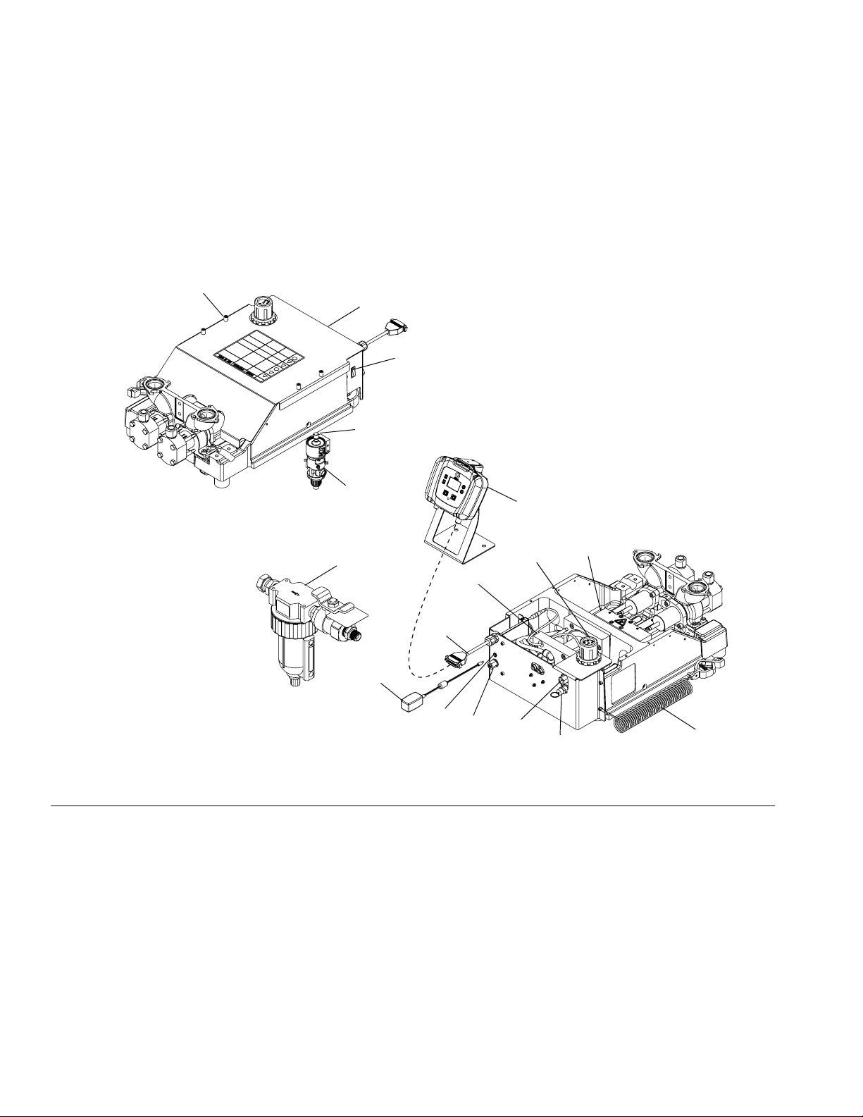
Machine
L
M
K
A
FIG. 1: Machine
Key:
A Power Switch
BAir Inlet
C System Air Pressure Relief Valve
D Local Control Module (LCM)
E Air Pressure Regulator
FDrive Block
G Air Motor
H 24V Power Input
J Dispense Head
K Snuff Back Adjustment Knob
L Machine Shield Screws
M Machine Shield
J
D
E
F
R
G
N
T
H
S
N Control Cable
P Ground Wire and Clamp
R Air/Water Separator Assembly with Vented Ball Valve
(Not Supplied - 24R707)
S Footswitch Connection
T 24V Power Supply
B
C
P
6 334135B
Page 7
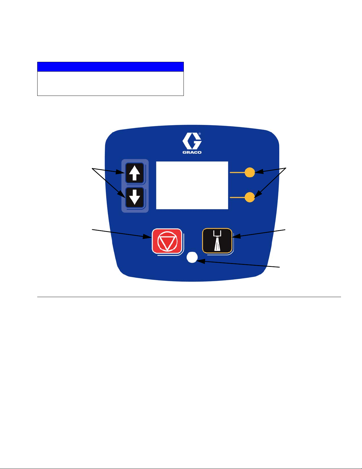
Local Control Module (LCM)
NOTICE
To prevent damage to soft key buttons, do not press
the buttons with sharp object such as pens, plastic
cards, or fingernails.
Component Identification
AC
AB
FIG. 2: LCM
Key:
AA Dispense Request or “Go” key
This key will dispense material and can not be disabled by
the user as a setup screen option.
AB System Shut-Down Key
This key will disable the machine (all outputs
de-energized) and will place the machine in disable mode.
This key is always active.
AC Up and Down Navigation Arrow Keys
Used to navigate between screens, navigate within a
screen, used for numerical entry or used to select
features.
AD Soft Key Inputs
Function of the keys will reflect the graphic provided to the
left of the respective key.
AD
AA
AE
AE Status LED
Solid - System is ready and operational.
Continuous Flashing - System is starting up or system is
being programmed.
Continuous Flashing with Pause - Indicates an error is
active. Refer to LCM Error Codes, page 39.
Flash Once with Pause - System is inactive.
334135B 7
Page 8
Component Identification
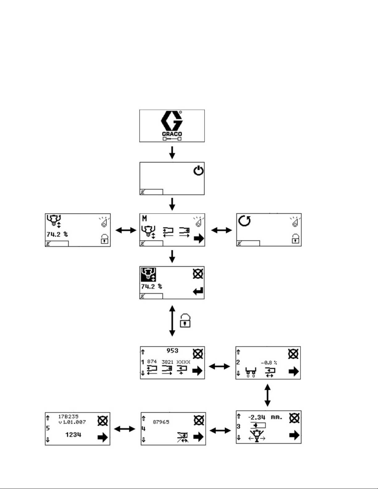
LCM Screen Navigation
For screen overview, refer to Appendix B - LCM Run
Screen Overview and Appendix C - LCM Setup
Screen Overview starting on page 62.
Shot Mode Screen
Splash Screen
Disable Mode Screen
Maintenance Mode
Run Screen
Operator Mode Screen
Setup Screen Password Set/Clear Screen
Mode Selection Programming Screen
Position Calibration Screen
Dispense Amount Prohibit and View Cycle
Phasing Shot Calibration
Open Dispense Valve
Position Calibration
8 334135B
Page 9

Component Identification
334135B 9
Page 10
Recommended Parts
Recommended Parts
Dispense Valve
Standard Dispense Valves, 255179 and 255181
See MD2 manual for parts information.
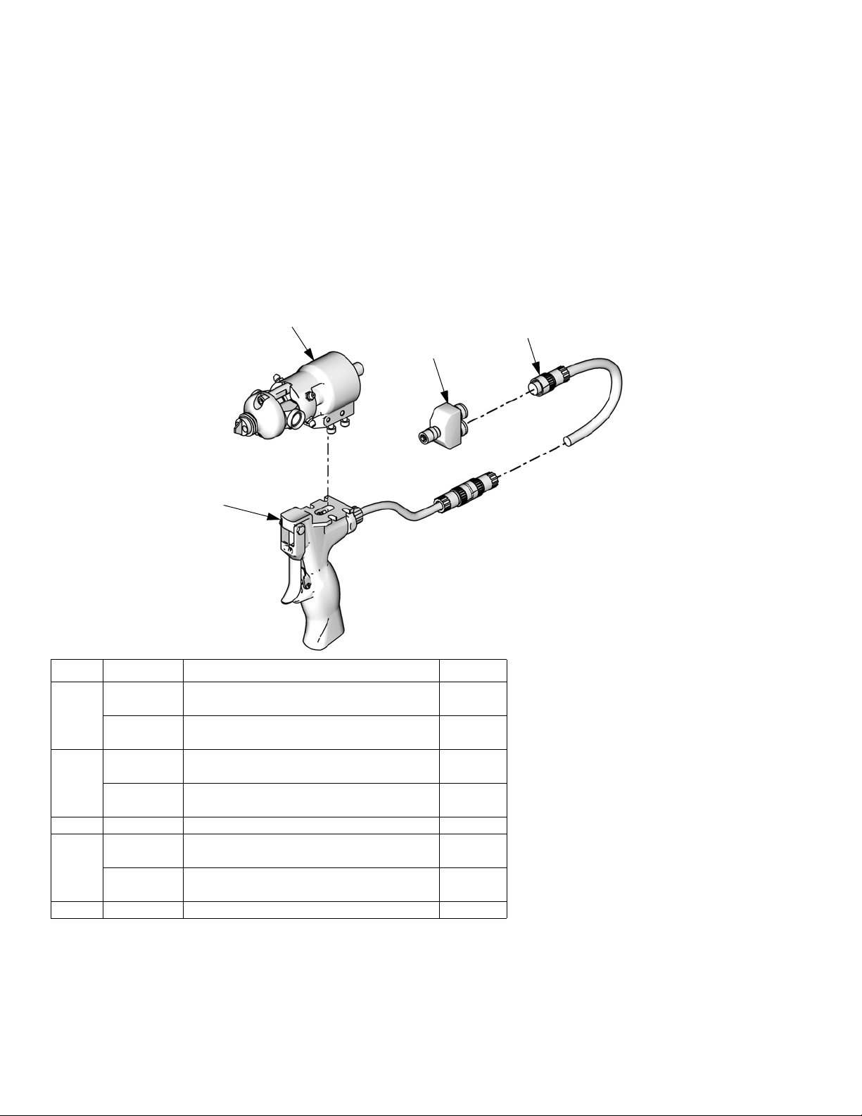
Gun Mounted MD2 Valves, LC0120 and LC0122
901a
902
903
901b
Assembly LC0120 Shown
Ref Part Description Quantity
901 LC0006 VALVE, assembly, 10:1, gun, electric
(assembly LC0122 only)
LC0004 VALVE, assembly, 1:1, gun, electric
(assembly LC0120 only)
901a 255181† VALVE, dispense, 10:1, soft seats
(assembly LC0122 only)
255179† VALVE, dispense, 1:1, soft seats
(assembly LC0120 only)
901b 255208 HANDLE, 2K dispense valve, electric 1
902 121198 CORD, euro, male, 4 pin, 3 wire, 6 m
(Series A Handles only)
123660 CORD, euro, male/female, 6 m
(Series B Handles only)
903 120953 CONNECTOR, splitter 1
ti12440a
1
1
1
1
1
1
† See MD2 manual for dispense valve and dispense valve handle parts information.
10 334135B
Page 11

Lever Actuated MD2 Valves, LC0121 and LC0123
Recommended Parts
1101a
1101b
Assembly LC0121 Shown
Ref Part Description Quantity
1101 LC0005 VALVE, assembly, 1:1, lever, electric
1
(assembly LC0121 only)
LC0007 VALVE, assembly, 10:1, lever, electric
1
(assembly LC0123 only)
1101a 255249 LEVER, 2K dispense valve 1
1101b 255181† VALVE, dispense, 10:1, soft seats
1
(assembly LC0123 only)
255179† VALVE, dispense, 1:1, soft seats
1
(assembly LC0121 only)
1102 121198 CORD, euro, male, 4 pin, 3 wire, 6 m
1
(Series A Handles only)
123660 CORD, euro, male/female, 6 m
1
(Series B Handles only)
1103 120953 CONNECTOR, splitter 1
1103
1102
ti12441a
† See MD2 manual for dispense valve and dispense valve lever parts information.
334135B 11
Page 12
Recommended Parts
Mixers
1301
1303
1302
Assembly LC0061 Shown
ti12442a
12 334135B
Page 13

Recommended Parts
Reference Number and Description
1301 1302 1303
Mixer
Package
Description
Mixer
Part No. (Quantity)
Shroud
Part No. (Quantity 1)
Sleeve
Part No. (Quantity 1)
LC0063 3/16 in. x 32 60/0206/50 (10) 94/0884-1/98 ---
LC0077 3/16 in. x 32 60/0206/50 (50) --- ---
LC0084 3/16 in. x 32 60/0206/50 (250) --- ---
LC0061 3/16 in. x 32 Luer Lock 16D012 (10) 16P448 60/0313/97
LC0082 3/16 in. x 32 Luer Lock 16D012 (50) --- ---
LC0089 3/16 in. x 32 Luer Lock 16D012 (250) --- ---
LC0057 1/4 in. X 24 60/0204/50 (10) 16P445 ---
LC0078 1/4 in. x 24 60/0204/50 (50) --- ---
LC0085 1/4 in. x 24 60/0204/50 (250) --- ---
LC0062 1/4 in. x 24 Luer Lock 60/0209/50 (10) 94/0883-M/98 60/0305/97
LC0083 1/4 in. x 24 Luer Lock 60/0209/50 (50) --- ---
LC0090 1/4 in. x 24 Luer Lock 60/0209/50 (250) --- ---
LC0058 3/8 in. x 24 60/0200/50 (10) 16P446 ---
LC0079 3/8 in. x 24 60/0200/50 (50) --- ---
LC0086 3/8 in. x 24 60/0200/50 (250) --- ---
LC0059 3/8 in. x 36 60/0201/50 (10) 16P447 ---
LC0080 3/8 in. x 36 60/0201/50 (50) --- ---
LC0087 3/8 in. x 36 60/0201/50 (250) --- ---
LC0060 3/8 in. combo 60/0202/50 (10) 16P447 ---
LC0081 3/8 in. combo 60/0202/50 (50) --- ---
LC0088 3/8 in. combo 60/0202/50 (250) --- ---
LC0295 1/2 in. x 24 60/0111-1/50 (10) 94/0885-24/98 ---
LC0296 1/2 in. x 36 60/0117-1/50 (10) 94/0885-36/98 ---
334135B 13
Page 14
Recommended Parts
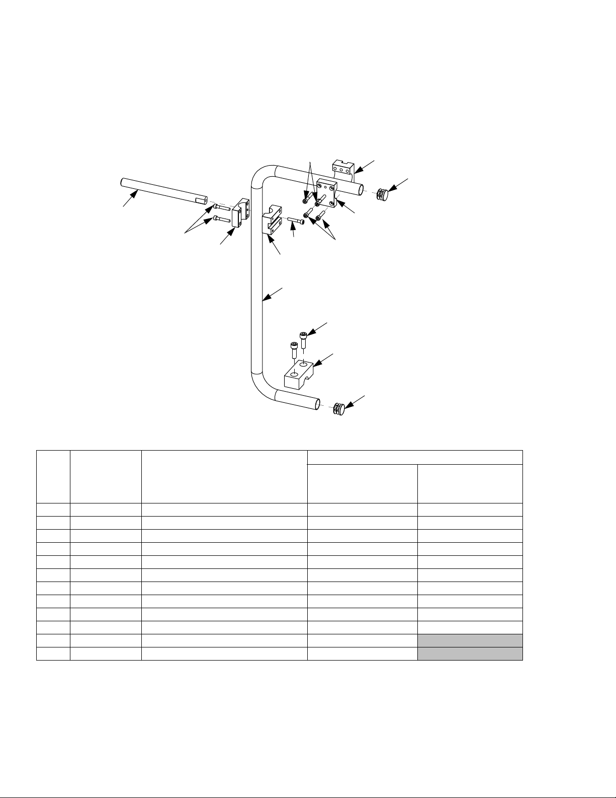
Applicator Mounting
Mast Mount, Controls and MD2 Applicator, LC0292
Mast Mount, Controls only, LC0293
805
804
802
803
804
801
812
803
811
802
814
806
807
811
Quantity
LC0292, BRACKET,
Ref Part Description
801 16P082 BASE, arm, mounting 1 1
802 16P409 BLOCK, mounting, front 2 1
803 16P550 BLOCK, mounting, rear 2 1
804 121194 SCREW 3 3
805 15K832 ARM, mounting, HMI 1 1
806 120913 SCREW 2 2
807 15M658 CLAMP 1 1
809* 121046 TUBE, 1/4 x 1/4 twin, polyurethane 6 6
810* 94/0705-1/96 FITTING, elbow, swivel 2 2
811 126510 PLUG, round, finishing 2 2
812 121273 SCREW, socket head 2
814 121013 SCREW, socket head 2
*Not shown.
mounting, valve, HMI
LC0293, BRACKET,
mounting, HMI
14 334135B
Page 15

Air Filter and Ball Valve, 24R707
704
703
701
705
702
Recommended Parts
Ref Part Description Quantity
701 --- VALVE, vented 2 way 1
702 157350 ADAPTER 1
703 106148 FILTER, air, 3/8 NPT 1
704 155665 UNION, adapter 1
705 --- NIPPLE, pipe 1
High Temperature Grease, 115982
Footswitch, 255244
334135B 15
Page 16

Recommended Parts
Tan ks
1 1/2 in. NPT Flanges, 24W417
8 Liter, Twin Polyethylene Tanks and Lids, 24W415
8 Liter, Twin Polyethylene Tanks and Lids, with Shut-Off Valves, 24W416
1004
1001
1018
1011
1008
1008
1006
1002
1019
1024
1015
1005
1025
1005
1010
1003
1007
1003
1009
1007
1023
1025
1020
1023
1014
1001
16 334135B
Page 17

Quantity
Ref Part Description
24W415 24W416 24W417
1001 95/0223/00 O-RING 2 4 1
1002 120901 O-RING 4 4
1003 120902 SCREW, M5x40mm 2 2
1004 120904 SCREW, M5x18mm 6 6 3
1005 120905 NUT, hex, lock M5 2 2
1006 120906 NUT, hex, lock M8 x 1.25 2 2
1007 120907 WASHER, plain #10 4 2
1008 120908 WASHER, plain M8 4 4
1009 120909 BREATHER 2 2
1010 120911 CLAMP, gap-free pinch hose 2 2
1011 120913 SCREW 2 2
1014 255280 VALVE , ball 2
1015 121013 SCREW, M5x25mm 6
1018 --- RING, lock 2 2
1019 --- FITTING, flange 2 2
1020 15K840 O-RING 2 2
1023 --- TANK, 8 liter 1 1
1024 15M226 BALLAST 1
15K842 BALLAST 1
1025 120915 CAP PLUG, square 2 2
1026* 15M237 FLANGE, 1-1/2 in. NPT 1
Recommended Parts
*Not Shown
334135B 17
Page 18

Recommended Parts
Hose Packages
Unheated, Non-Recirculating Hose
1402
1404
1403
1401
ti12446a
1
Apply thread sealant tape to male npt threads before assembly.
Assembly LC0801 Shown
Reference Number and Description
1401 1402 1403 1404
Hose Package Description
Hose Assembly 90 Deg Elbow Adapter Bushing
LC0801 3/16 in. x 30 in. 16C501 94/0144-S/25 94/1000/98 94/0488/98
LC0802 3/16 in. x 120 in. 16C506 94/0144-S/25 94/1000/98 94/0488/98
LC0803 3/16 in. x 180 in. 16C507 94/0144-S/25 94/1000/98 94/0488/98
LC0804 1/4 in. x 30 in. 16C510 94/0148-S/25 J6900040
LC0805 1/4 in. x 120 in. 16C515 94/0148-S/25 J6900040
LC0806 1/4 in. x 180 in. 16C516 94/0148-S/25 J6900040
LC0807 3/8 in. x 30 in. 16C519 94/0149-S/25 94/1007/98
LC0808 3/8 in. x 120 in. 16C524 94/0149-S/25 94/1007/98
LC0809 3/8 in. x 180 in. 16C525 94/0149-S/25 94/1007/98
LC0400* 3/8 in. x 30 in. 16D261 94/0149-S/25 94/1007/98
LC0401* 3/8 in. x 120 in. 16D266 94/0149-S/25 94/1007/98
LC0402* 3/8 in. x 180 in. 16D267 94/0149-S/25 94/1007/98
LC0810 1/2 in. x 30 in. 16C529 94/0150-S/25 94/1009/98
LC0811 1/2 in. x 120 in. 16C534 94/0150-S/25 94/1009/98
LC0812 1/2 in. x 180 in. 16C535 94/0150-S/25 94/1009/98
LC0403* 1/2 in. x 30 in. 16D271 94/0150-S/25 16C399
LC0404* 1/2 in. x 120 in. 16D276 94/0150-S/25 16C399
LC0405* 1/2 in. x 180 in. 16D277 94/0150-S/25 16C399
LC0813 3/4 in. x 120 in. 16C544 94/0153-S/25 94/1083/98
LC0814 3/4 in. x 180 in. 16C545 94/0153-S/25 94/1083/98
LC0406* 3/4 in. x 120 in. 16D286 94/0153-S/25 94/1083/98
LC0407* 3/4 in. x 180 in. 16D287 94/0153-S/25 94/1083/98
Quantity 1 1 11
* High pressure hoses (3500 psi, 24 MPa, 241 bar)
18 334135B
Page 19

Recommended Parts
334135B 19
Page 20

Recommended Parts
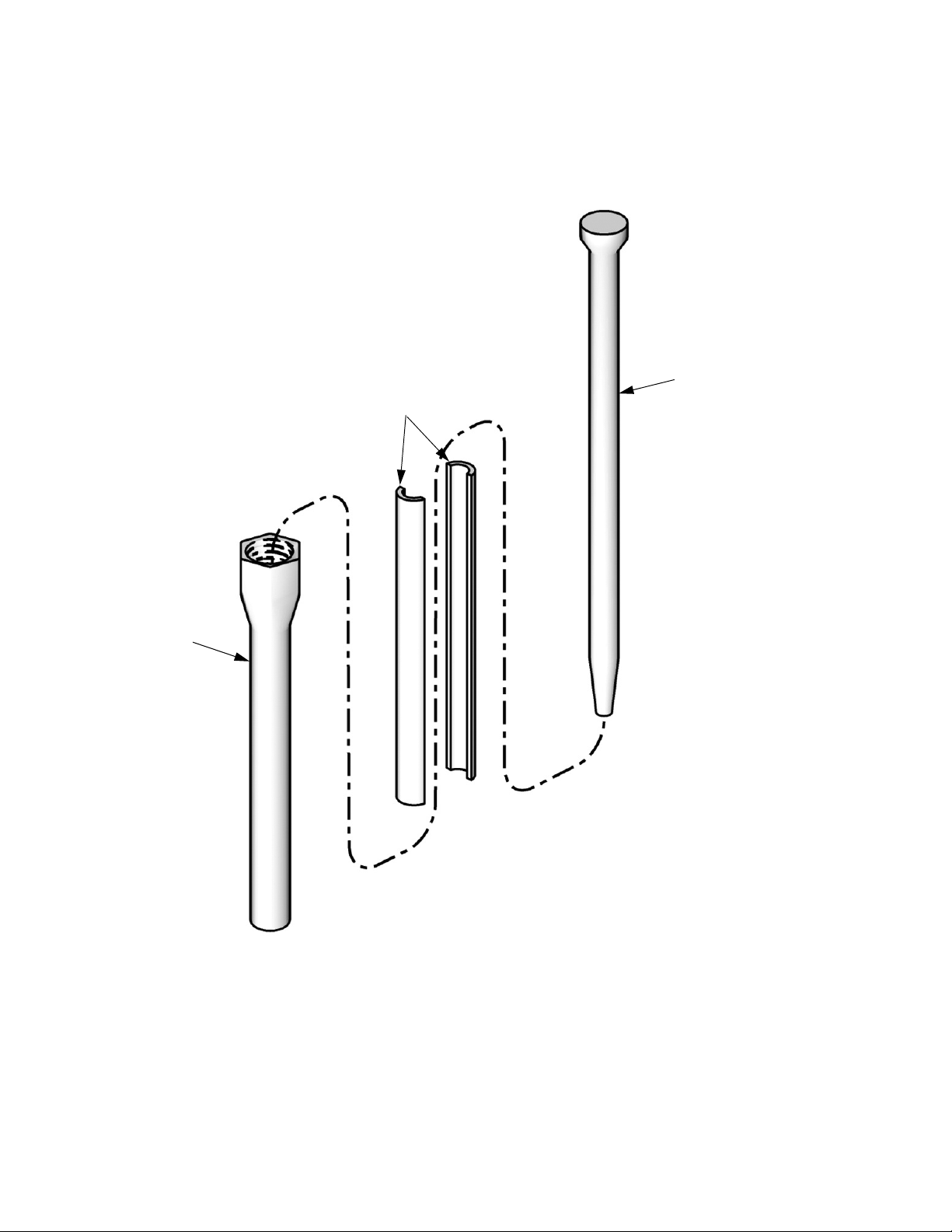
Piston Package
605
606
606
601
1
603
602
604
1
Arrow on cylinder must point to the o-ring (606) on the right.
Nylon Piston, Stainless Steel Metering Tube Assemblies
Reference Number and Description
601 602 603† 604 605 606
Piston
Package
LC1080 LCC080 LCB080
LC1100 LCC100 LCB100
LC1120 LCC120 LCB120
LC1140 LCC140 LCB140
LC1160 LCC160 LCB160
LC1180 LCC180 LCB180
LC1200 LCC200 LCB200
LC1220 LCC220 LCB220
LC1240 LCC240 LCB240
LC1260 LCC260 LCB260
LC1280 LCC280 LCB280
LC1300 LCC300 LCB300
LC1320 LCC320 LCB320
LC1360 LCC360 LCB360
LC1400 LCC400 LCB400
LC1440 LCC440 LCB440
LC1480 LCC480 LCB480
LC1520 LCC520 LCB520
LC1560 LCC560 LCB560
LC1600 LCC600 LCB600
LC1640 LCC640 LCB640
LC1720 LCC720 LCB720
LC1800 LCC800 LCB800
LC1880 LCC880 LCB880
LC1960 LCC960 LCB960
Quantity 1 1 1 1 1 2
Tube ,
pump
Nylon
Piston
Washer
15M089
15M099
15M100
15M101
Ring, support,
piston
15K887
15K888
15K890
Screw O-ring
120933 120874
ti12438a
20 334135B
Page 21

UHMW Piston, Stainless Steel Metering Tube Assemblies
Reference Number and Description
601 602 603† 604 605 606
Piston
Package
LC2160 LCC160 LCA160
LC2180 LCC180 LCA180
LC2200 LCC200 LCA200
LC2220 LCC220 LCA220
LC2240 LCC240 LCA240
LC2260 LCC260 LCA260
LC2280 LCC280 LCA280
LC2300 LCC300 LCA300
LC2320 LCC320 LCA320
LC2360 LCC360 LCA360
LC2400 LCC400 LCA400
LC2440 LCC440 LCA440
LC2480 LCC480 LCA480
LC2520 LCC520 LCA520
LC2560 LCC560 LCA560
LC2600 LCC600 LCA600
LC2640 LCC640 LCA640
LC2720 LCC720 LCA720
LC2800 LCC800 LCA800
LC2880 LCC880 LCA880
LC2960 LCC960 LCA960
Quantity 1 1 1 1 1 2
Tube ,
pump
UHMW
Piston
Washer
15M099
15M100
15M101
Ring, support,
piston
15K887
15K888
15K890
Screw O-ring
120933 120874
Recommended Parts
† For custom piston packages, washer (603) part num-
ber will change by piston size as follows:
For piston sizes 80-100cc: 15M089
For piston sizes 101-159cc: Washer not used.
For piston sizes 160-285cc: 15M099
For piston sizes 286-646cc: 15M100
For piston sizes 647-960cc: 15M101
334135B 21
Page 22

Pump Tube Combination Information
Pump Tube Combination Information
Pump Tube Combination Information Power Factor
Ratio
(X:1)
Large Piston
(mm)
1 960 960 12.4 71.0 2 5
1 640 640 8.3 47.3 4 8
1 480 480 6.2 35.5 5 11
1 320 320 4.1 23.7 7 16
1 240 240 3.1 17.7 10 21
1 160 160 2.1 11.8 14 ✖
1 120 120 1.6 8.9 19 ✖
180 80 1.0 5.9 29 ✖
1.50 240 160 2.6 14.8 11 26
1.50 960 640 10.4 59.1 3 6
1.50 480 320 5.2 29.6 6 13
1.50 120 80 1.3 7.4 23 ✖
2 960 480 9.3 53.2 3 7
2 640 320 6.2 35.5 5 11
2 480 240 4.7 26.6 6 14
2 320 160 3.1 17.7 10 21
2 240 120 2.3 13.3 13 29
2 160 80 1.6 8.9 19 ✖
3 960 320 8.3 47.3 4 8
3 480 160 4.1 23.7 7 16
3 240 80 2.1 11.8 14 ✖
4 960 240 7.8 44.3 4 9
4 640 160 5.2 29.6 6 13
4 480 120 3.9 22.2 8 17
4 320 80 2.6 14.8 11 26
5.33 640 120 4.9 28.1 6 14
6 960 160 7.3 41.4 4 9
6 480 80 3.6 20.7 8 18
8 960 120 7.0 39.9 4 10
8 640 80 4.7 26.6 6 14
10 800 80 5.7 32.5 5 12
12 960 80 6.7 38.4 4 10
Small Piston
(mm)
Minimum
Shot Size (cc)
Maximum
Shot Size (cc)
3 in.
Air Motor
in. Air Motor
4.5
✖ Pump tube combination is not recommended.
22 334135B
Page 23

Installation
Installation
Grounding
The equipment must be grounded to reduce the risk of
static sparking and electric shock. Electric or static
sparking can cause fumes to ignite or explode.
Improper grounding can cause electric shock.
Grounding provides an escape wire for the electric
current.
General Grounding Guidelines
Pump: use ground wire and clamp (P). Refer to page 6
for component identification. Connect ground wire and
clamp to a true earth ground.
Fluid hoses: use only electrically conductive hoses.
Dispense Valve: ground through a proper connection to
a fluid hose and grounded pump.
Fluid supply container: follow local codes.
Machine Installation
Pump shaft, polyethylene (PE) tank lid, and PE tank lid
gasket are coated with Krytox grease. Wear protective
gloves and cover exposed skin to avoid possible skin
irritation on contact. Read Krytox MSDS to know the
specific hazards, and follow manufacturer’s warnings.
Locate Machine
1. Locate a bench top or open floor area to mechanically mount the machine. Ensure the location has
access to compressed air and AC power and is well
ventilated.
2. Place the machine on the designated location. Allow
the machine to rest on the rubber feet provided.
Mount Machine, if Needed
3. Remove the shield locking screws on both sides,
then remove the protective shield.
4. Attach the frame to the selected location by installing fasteners (not provided with unit) through the
two mounting holes. See F
IG. 3.
Object being sprayed: follow local codes.
Solvent pails used when flushing: follow local code.
Use only conductive metal pails, placed on a grounded
surface. Do not place the pail on a nonconductive surface, such as paper or cardboard, which interrupts
grounding continuity.
8 in.
(203 mm)
F
IG. 3: Mounting Holes
10 in.
(254 mm)
0.375 in.
(10 mm)
334135B 23
Page 24

Installation
Install Pump Tubes
See Piston Package on page 20 and Nylon and
UHMW Piston Replacement Kits on page 65 for kit
numbers.
NOTE: Ensure that high volume and low volume pump
tubes are installed on the correct side of the machine.
High Volume
Low Volume
5. Secure the piston support ring, piston, and washer
to the piston shaft using the piston screw. Tighten
the piston screw until the screw stops rotating, then
turn the screw an additional 1/8 turn.
7. Install the pump cap onto the assembly using the
four bolts. Finger tighten the bolts, then torque the
bolts to 350 in-lb (40 N•m) in a crisscross pattern.
1
4
3
2
Install the Chemical Hoses.
Install the chemical hoses and tighten to prevent leaks.
NOTE: Ensure that high volume and low volume hoses
are installed on the correct side of the machine.
Install the Hydracheck Kit.
Perform HydraCheck Kit Installation, 24W336 starting
on page 40.
6. Lubricate the tube pump o-rings. Install the tube
pump and o-rings as shown.
Install the Tanks.
Refer to the PR70 and PR70v Feed Systems, Instructions-Parts manual for details.
Install the Dispense Valve and Support Arm, if
needed.
Install the dispense valve as necessary to prevent
movement. Connect the required air lines from the dispense valve to the machine.
Air to Close (O)Air to Open (I)
24 334135B
Page 25

Installation
Connect the Footswitch or External Device.
Connect Pressurized Air Input
8. Install an air inlet bleeding ball valve and air filter kit
(not provided with unit, but available as kit 24R707)
at the 1/4 NPT female air inlet.
NOTICE
The system must have a bleed-type ball valve that
bleeds pressure downstream when closed. Otherwise, the supplied air will need to be disconnected
from the system whenever the pressure is relieved.
Electrical Requirements
11. Connect AC power (100-240V, 50/60 Hz, single-phase) to the power supply provided. Connect
the power supply to the machine as shown.
NOTE: The system must use an air filter with a minimum
flow rate of 30 scfm.
9. Close the ball valve.
NOTE: Air supply pressure must be between 80 psi (550
kPa, 5.5 bar) and 100 psi (690 kPa, 6.9 bar). Recommended pressure is 100 psi (690 kPa, 6.9 bar).
Ground System
The equipment must be grounded to reduce the risk of
static sparking. Static sparking can cause fumes to
ignite or explode. Grounding provides an escape wire
for the electric current.
10. Follow Grounding instructions on page 23.
334135B 25
Page 26

Setup
Setup
Before setting up the machine, the user needs to be
familiar with the LCM screens. Refer to Appendix A -
LCM Icon Overview and Appendix B - LCM Run
Screen Overview, starting on page 60.
Perform Startup, page 33, to access the LCM screens.
Piston Position Calibration
FIG. 4: Position Calibration Screen
The position sensor assigns a numeric value to the location of the piston. Higher numbers indicate the piston is
extended and lower numbers indicate the piston is
retracted.
3. Place a waste container under the dispense valve to
capture any dispensed material.
4. Ensure the system air pressure is on by opening the
vented ball valve and the system air pressure regulator shows air pressure in the system.
Retracted Piston Position
5. With air pressure applied to the machine, high light
the Retract Piston button ( ).
6. Press the Dispense Request button ( ). The pis-
ton will fully retract and a number from 1250 to 1600
will be displayed next to the Retract Piston button. If
a number outside of this range is displayed, ensure
the air cylinder air line connections are not switched
and that the linear position sensor is properly
installed.
7. Press the Enter button ( ) to accept the value or
press the Abort/Cancel button ( ) to keep the
previous value.
The Piston Position Calibration procedure teaches the
machine the location of the most extended piston posi-
tion ( ), the most retracted piston position ( ),
and the position where the piston engages the pump
cylinder ( ).
Perform the Piston Position Calibration procedure
when first setting up the machine. Also perform this procedure if the linear position sensor, piston, or any electronic component has been replaced. Press the Setup
Screen button ( ) to enter the setup screens.
Prepare Machine for Calibration
1. Ensure that both piston shafts are screwed all the
way into the drive block.
2. Navigate to the Position Calibration Screen.
26 334135B
Extended Piston Position
8. With air pressure applied to the machine, high light
the Extend Piston button ( ).
9. Press the Dispense Request button ( ). The pis-
ton will fully extend and a number 3600-3900 should
be displayed. If a number outside of this range is
displayed, ensure the air cylinder air line connections are not switched and that the linear position
sensor is installed correctly.
NOTE: If the piston does not extend after pressing the
Dispense Request button ( ) the air pressure may
need to be increased. Use system air pressure regulator
to increase the air pressure in increments of 10 psi until
the piston activates. Material will be dispensed when
adequate pressure is achieved.
Page 27

Setup
10. Press the Enter button ( ) to accept the new
value or press the Abort/Cancel button ( ) to
keep the previous value.
Engaged Piston Position
11. Close the vented ball valve to eliminate the air pressure to the system.
12. High light the metering tube entrance position but-
ton ( ).
13. With no air pressure in the system, press the Dis-
pense Request button ( ).
14. Move the piston drive block until it just begins to
engage the cylinder using one of the following methods. No material should be dispensed.
Manually Move the Piston Drive Block
16. Press the Enter button ( ) to accept the value or
press the Abort/Cancel button ( ) to keep the
previous value.
Prepare Machine for Operation
17. High light the Retract Piston button ( ).
18. Press the Dispense Request button ( ).
19. Open the vented ball valve to enable system pressure.
The piston will fully retract when the system is pressurized. To avoid injury, ensure the machine shield is
installed.
20. Adjust the system air pressure regulator to increase
air pressure to standard operating pressure for your
application.
In the steps below, ensure pressure is off or piston
may activate and pinch fingers against machine block.
a. Perform Pressure Relief Procedure on
page 33.
b. Remove the machine cover.
c. With no air pressure in the system, manually
push the piston drive block until the piston
engages the cylinder and resists movement. A
number from 2000 to 2400 will be displayed.
NOTE: If a number outside of this range is displayed,
ensure the air cylinder air line connections are not
switched and that the linear position sensor is properly
installed.
15. Ensure there is no material in the waste container
under dispense valve. The piston block moved too
far and caused material to be dispensed if there is
material in the waste container. Go back to step 14
if the piston moved too far.
21. Navigate to the Shot Mode Screen or Operator
Mode Screen.
334135B 27
Page 28

Setup
Prime the Dispense Head
NOTICE
If the dispense head is not primed, chemical crossover may occur resulting in cured material in the dispense head, hoses, and/or pumps.
1. Remove static mixer from the dispense head if
installed.
2. Turn snuff-back adjustment knob fully clockwise.
This will prevent the dispense valve from closing
between priming shots.
3. Use a 4 mm hex key to loosen the screws holding
the dispense head in place.
9. Select a large size shot.
10. Hold a waste container at the end of the dispense
head and press the Dispense Request button
( ) or the footswitch.
11. Repeat the previous step until no air comes out of
the dispense valve.
12. If phasing adjustments and ratio checking are not
required, use the following procedure to attach the
static mixer.
a. Attach the static mixer with the dispense head
pointed up.
b. Hold waste container at end of dispense head
and press the Dispense Request button ( )
or the footswitch.
c. Repeat the previous steps until static mixer has
been purged of air.
ti12391a
F
IG. 5: Prime Dispense Head
4. Rotate or remove the dispense head so the tip is
above the fluid input hoses.
5. Use a 4 mm hex key to tighten screws holding dispense head in place if applicable.
6. Route the fluid hoses connected to the dispense
head so they are always below the dispense head.
This ensures any air in the hoses will travel to the
dispense head.
7. Navigate to the Shot Mode Screen or Operator
Mode Screen.
13. Use a 4 mm hex key to loosen screws holding dispense head in place.
14. Rotate dispense head back to normal dispensing
position.
15. Use a 4 mm hex key to tighten the screws holding
the dispense head in place.
16. Adjust snuff back to proper setting for operation.
See Adjust Dispense Valve Snuff Back on
page 31.
8. Ensure there is a sufficient amount of material in the
tanks.
28 334135B
Page 29

Setup
Phasing Adjustment
FIG. 6: Phasing Calibration Screen.
When the machine executes a shot, materials from
Tank A and Tank B enter the static mixer where they are
mixed and then dispensed. In order for the materials to
mix at the desired ratio, both materials must enter the
static mixer at the same time. The timing of the materials
entering the static mixer is dependent on the adjustment
of the phase adjustment screw for each piston.
Adjust Dispense Quantity
6. Press the Phasing shot button ( ) to enter
phasing mode.
7. Press the Dispense Request button ( ) or the
footswitch to dispense a very small amount of material.
8. Adjust the displayed percentage if more than a couple drops of either material was dispensed or if no
material was dispensed from both sides.
• If too much material was dispensed, decrease
the phasing percentage. If necessary, use the
arrow keys to switch the percentage from positive to negative.
• If no material was dispensed, increase the dis-
played percentage. If necessary, use the arrow
keys to switch the percentage from negative to
positive.
Prepare the Machine
1. Place a waste container under the dispense valve to
catch dispensed material.
2. Remove the static mixer from the dispense valve.
3. Install the ratio check nozzle onto the dispense
valve.
ti12392a
IG. 7: Ratio Check Nozzle
F
4. If necessary, place a stand under the ratio check
nozzle to support the waste container close to the
nozzle.
5. Navigate to the Phasing Shot Calibration Screen.
334135B 29
Page 30

Setup
Adjust Phasing
003
002
001
Key:
001 Piston Shaft
002 Locking Nut
003 Phase Adjustment Screw
ti12389a
9. Watch the dispense valve carefully to observe which
material is dispensed first. Press the Dispense
Request button ( ) or the footswitch to dispense
material.
b. Hold the phase adjustment screw (003) sta-
tionary with a 13 mm wrench.
c. Use a 7 mm wrench to turn the piston
shaft (001) counterclockwise 1/4 turn or
less to move the A piston forward.
NOTE: It is highly recommended that all of the phasing
adjustment be done to one side or the other; not both.
NOTE: Ensure the piston shaft and phase adjustment
screw do not rotate while tightening the locking nut (002)
in the following step.
11. Hold piston shaft (001) and phase adjustment
screw (003) in place with a 7 mm and 13 mm
wrench and tighten locking nut (002) against phase
adjustment screw with a 13 mm wrench.
12. Watch the dispense valve carefully to observe which
material is dispensed first. Press the Dispense
Request button ( ) or the foot switch to dispense
material. If one material exits the dispense nozzle
before the other, go back to step 10.
10. If the materials do not exit the dispense valve at the
same time, adjust the piston Phase Adjustment
Screw (003) as follows.
• If the A side material exits the dispense nozzle
before the B side material ( ):
a. Use two 13 mm wrenches to break loose
the locking nut (002) from the phase adjustment screw (003) on the B material side.
b. Hold the phase adjustment screw (003) sta-
tionary with a 13 mm wrench.
c. Use a 7 mm wrench to turn the piston
shaft (001) counterclockwise 1/4 turn or
less to move the B piston forward.
• If the B side material exits the dispense nozzle
before the A side material ( ):
a. Use two 13 mm wrenches to break loose
the locking nut (002) from the phase adjustment screw (003) on the A material side.
Exit Calibration Mode
13. Navigate to the Shot Mode Screen or Operator
Mode Screen.
30 334135B
Page 31

Adjust Dispense Valve Snuff Back
At the end of a shot, a small amount of material is drawn
back into the static mixer to prevent extra material from
being dispensed. If too much snuff back occurs, air will
enter the static mixer and can travel up into the dispense
valve. If too little snuff back occurs, the materials may
drip out of the static mixer and affect dispense quantity.
It is most efficient to adjust the snuff back while material
is dispensing, but it can also be adjusted when there is
no air pressure in the system.
1. Navigate to the Shot Mode Screen or Operator
Mode Screen.
Setup
2. Select a small size shot.
3. If a static mixer is not in place, install one, then
prime the machine. See Prime the Dispense Head,
page 28.
4. Place a waste container under static mixer.
5. Press the Dispense Request button ( ).
6. Inspect the tip of the static mixer for dripping material or for air bubbles traveling up the mixer.
7. Perform another shot and, while dispensing, adjust
the snuff-back adjustment knob as follows.
• If an air bubble is moving up the mixer, turn the
knob clockwise to decrease snuff back.
• If material is hanging from the tip of the mixer,
turn the knob counterclockwise to increase
snuff back.
8. Repeat step 7 until snuff back is adjusted as
desired.
334135B 31
Page 32

Setup
Adjust Open Dispense Valve (ODV) Timing
When a shot is performed, the dispense valve needs to
open at a precise time for material to be dispensed
properly. If the dispense valve opens too early, material
may drain from the static mixer before the shot starts. If
the dispense valve opens too late, pressure may build in
the machine before the dispense valve opens, causing
material to forcefully spray out of the mixer.
The Open Dispense Valve Timing should also be
adjusted for material viscosity. Thicker materials should
have the dispense valve open earlier and thinner materials should have the dispense valve open later.
A positive value for Open Dispense Valve Timing indicates the dispense valve will open after the piston is
engaged in the cylinder. A negative value indicates the
dispense valve will open before the piston is engaged in
the cylinder.
If a high positive number is entered for ODV timing, such
as 6.0 mm, the dispense valve may not open resulting in
the fluid stalling against the dispense valve. The fluid in
the hose lines will remain under pressure until the piston
is manually retracted using the Manual screen, see
Operator Mode Screen.
FIG. 8: Open Dispense Valve Position Calibration
1. Navigate to the Open Dispense Valve Position
Calibration Screen.
2. Press the Dispense Valve Open Position Adjust but-
ton, ( ).
3. Use the up and down arrows to enter a value for the
ODV Timing.
4. Press the Enter button ( ) to accept the new
value or press the Abort/Cancel button ( ) to
keep the previous value.
32 334135B
Page 33

Operation
Operation
Startup
1. Locate the power switch at rear of machine and turn
the power on. The display module will automatically
turn on and begin to load.
2. Open the vented ball valve (not provided).
3. If the machine is in Disabled Mode, press the Power
On button ( ) to exit Disabled mode and to
select a new operating mode. Press the Enter but-
ton ( ) to accept the new operating mode.
FIG. 9: Disabled Mode
Pressure Relief Procedure
Follow the Pressure Relief Procedure whenever
you see this symbol.
This equipment stays pressurized until pressure is
manually relieved. To help prevent serious injury from
pressurized fluid, such as skin injection, splashing
fluid and moving parts, follow the Pressure Relief
Procedure when you stop spraying and before
cleaning, checking, or servicing the equipment.
1. Place a waste container below the dispense valve.
2. Navigate to the Maintenance Mode Run Screen.
3. Press the Shot Mode Designation button ( ) on
the Maintenance Mode Run Screen to relieve
chemical pressure. Press the Shot Mode Designa-
tion button ( ) again to close the dispense valve.
4. Press the Machine Disable Mode button ( ).
5. Close the vented ball valve.
334135B 33
Page 34

Operation
Shutdown
If the machine is to remain idle for an extended period of
time, perform the following steps.
1. If installed, remove static mixer from the end of the
dispense valve.
2. Place a container below the dispense valve and
activate a small shot to flush mixed material out of
the valve.
3. Relieve pressure. See Pressure Relief Procedure,
page 33.
4. With a clean rag and cotton swabs, clean the end of
the dispense valve.
5. Install the nightcap on the dispense valve. Refer to
MD2 Valve, Instructions manual for part information.
34 334135B
Page 35

Maintenance
Maintenance
Schedule
Action Schedule Procedure
Check Water/Air Separator
(Not provided)
Check Desiccant Dryer (only
installed if chemical is moisture
sensitive)
Check Tanks Daily before use 1. Check material levels and refill as necessary.
Check Dispensing Ratio Daily before use or as
Clean Pump Shafts Daily after shutdown See Clean the Pump Shafts on this page.
Clean Dispense Head Daily See Shutdown on page 34.
Disassemble and Clean Dispense
Head
Upgrade LCM As required See Install Upgrade Token on page 36
Daily before use 1. Check water/air separator for water.
2. Open valve at base of water/air separator to purge
water.
Daily before use 1. Check the color of the desiccant
2. Replace as required.
2. Verify the material reservoirs are vented properly.
See Phasing Adjustment page 29.
required
As required See Disassemble and Clean the Dispense Head on
this page.
Clean the Pump Shafts
1. Close the vented ball valve at the left, rear of the
machine.
2. Press the Machine Disable Mode key ( ).
3. Push the piston block to the fully retracted position.
4. Clean both pump shafts with a compatible solvent
and lubricate with mesamoll, silicon oil, or other
compatible lubricant.
Disassemble and Clean the Dispense Head
1. Relieve pressure. See Pressure Relief Procedure,
page 33.
2. Remove the dispense head from machine.
3. Dismantle the dispense head. See MD2 Dispense
Valve manual referenced at the beginning of this
manual.
4. Clean all parts.
5. Lubricate all parts with a thin coat of mesamoll, silicon oil, or compatible lubricant.
6. Reassemble the dispense head.
7. Reinstall the dispense head on machine.
334135B 35
Page 36

Maintenance
Install Upgrade Token
This procedure applies to the Local Control Module
(LCM).
1. Disconnect power to the module.
2. Remove token access panel.
F
IG. 10: Remove Access Panel
3. Press firmly the token into the slot.
NOTE: There is no preferred orientation of the token.
4. Restore power to the module. The red LED will flash
rapidly to signal that software is loading. When the
red LED stops flashing, the software is done loading.
5. Disconnect the power to the module.
6. Remove the token.
7. Replace the token access panel.
8. Restore power to the module.
9. Verify new software versions on the Setup Screen
Password Set/Clear Screen screen. Refer to
PKE 2903 found at www.graco.com for the latest
software version by utilizing the search box.
36 334135B
Page 37

Troubleshooting
Troubleshooting
Before starting any troubleshooting procedures, perform
the following procedure.
1. Relieve pressure. See Pressure Relief Procedure,
page 33.
2. Disconnect AC power from the machine.
Problem Cause Solution
Display Module completely dark No power Verify cable is plugged in.
Loose connection Tighten all cables on Display Module.
Bad display module Replace Display Module.
No or incorrect amount of material
dispensed from either side.
Piston stalled Input air reduced or removed Reconnect input air line to machine.
Significant material leaking from
pump rear seal
Material dispensed not correct volume
Tank empty Fill tank with material.
Tank clogged Verify no obstruction in the tank.
Air in material Prime the machine until the air is
Check valve malfunction Remove; clean or replace check
Piston worn or broken Remove and replace piston if worn.
Mixer blocked Replace static mixer.
Open Dispense Valve (ODV) adjustment too late
Blocked check valve Remove check valve; clean and
Air cylinder failure Remove air cylinder and reinstall air
Pump shaft worn and/or shaft seal
worn
Machine air pressure has changed
since calibration.
Not enough material in one or more
tanks
Mixer has slight obstruction Replace static mixer. Prime machine.
Check valve malfunction Remove check valve; clean or
Piston worn or broken Replace piston.
3. Allow the machine to cool if the machine has a heat
control option.
Try the recommended solutions in the order given for
each problem to avoid unnecessary repairs. Verify all
circuit breakers, switches, and controls are properly set
and wiring is correct.
Verify rear AC Power switch is ON.
removed.
valve.
Increase air pressure regulator
adjustment.
Readjust the ODV setting to occur
sooner.
replace.
cylinder parts as necessary.
Remove pump shaft assembly, and
reinstall rear pump rebuild kit.
Readjust air pressure regulator to
value used when machine was calibrated, or recalibrate machine.
Check tank levels; fill and prime as
necessary.
replace as necessary.
334135B 37
Page 38

Troubleshooting
Problem Cause Solution
Machine dispensing off ratio One tank is empty Check tank levels. Add material if
necessary.
Tank ball valve closed Open tank ball valve. Prime machine.
Machine out of phase Re-phase machine.
Check valve malfunction Remove check valve; clean or
replace as necessary.
Piston worn or broken Replace piston.
Pumps drawing material back from
valve hose
Check valve stuck open Remove check valve, clean or
replace as necessary.
38 334135B
Page 39

Troubleshooting
LCM Error Codes
If an error condition exists, the front Panel LED will blink the number of times corresponding to the error code number,
pause, then repeat. After the user acknowledges the generated error screen, the error number will appear on the bottom left-hand side of the main run screen, and the described blink sequence will continue. If more than one error is
present, all will be presented, separated by commas. When the condition is cleared, the corresponding error number
will be removed from the main run screen. If an error code is present, the machine will not dispense.
Trigger
Code Name Type Causes Fixes
Condition
E3 Improper
Machine Calibration
E4 Bad Linear
Position Sensor
E5 Stuck key Alarm 1. Key is in an active
Alarm Machine has not been
calibrated or has been
calibrated incorrectly.
Alarm 1. Connection to position
sensor disconnected.
2. Power to position sensor interrupted.
3. Bad position sensor.
state.
2. Tactile switch on LCM
is shorted or broke.
Perform pump position
entries in Position Calibra-
tion Screen. Retract position must be less than
metering tube position, which
should be less than the fully
extend position.
1. Verify connections to the
sensor.
2. Verify proper readings from
sensor on setup screen 1.
3. Replace sensor
Replace LCM Module. If key is
When
requesting a
dispense
operation.
Invalid readings from the
sensor.
detected to
be active for
more than 30
seconds.
334135B 39
Page 40

Repair
Repair
HydraCheck Kit Installation, 24W336
Be sure that system pressure is relieved and disabled
before proceeding.
F
IG. 11: HydraCheck Installation - Fixed Ratio Base
NOTE: The HydraCheck kit is intended to be used with
low viscosity materials to minimize splashing. It is not
intended to be used as a timer or flow control device.
Prepare Machine for Kit Installation
1. Navigate to the Maintenance screen.
2. Press the Retract Piston button ( ).
3. Relieve system pressure. See Pressure Relief Pro-
cedure, page 33.
4. Loosen the machine shield screws.
5. Remove the machine shield.
40 334135B
Install HydraCheck Shock
6. Install the shock absorber through the opening in
the pump sub-assembly with the groove for the snap
ring on the back of the pump assembly. The shock
absorber can be inserted through the front.
7. Install the shock snap ring (included with shock, not
shown) onto the shock absorber in the groove farthest from the pump sub-assembly.
8. Install set screw and torque to 85 in-lb (9.6 N•m).
Page 41

Install Adjustment Screw/Cap
9. Loosely install hex nut and adjustment cap onto the
air cylinder shaft.
Adjust the Adjustment Screw/Cap
10. Push the drive block forward until resistance is felt
when it engages the cylinder. Make sure the resistance is not due to shock absorber contact with the
adjustment screw or adjustment cap.
11. Adjust the adjustment screw or adjustment cap until
it contacts the shock absorber.
12. Hold the adjustment cap in place and tighten the
hex nut against the adjustment cap.
Prepare Machine for Operation
13. Open the ball valve to pressurized the system.
Adjust Shock Resistance
Repair
14. Execute a shot to see how the shock absorber
affects the speed of the drive block.
15. The shock absorber has a numeric scale on one
side. Rotate the knob with the scale to a higher
value for more resistance. Rotate the knob to a
lower value for less resistance.
16. Repeat these steps until the desired resistance is
achieved.
334135B 41
Page 42

Repair
Air Cylinder Rebuild Instructions
2
3
3
3
3
3
1
4
1
Finger tighten all (4) bolts prior to wrench tightening. For wrench tightening,
turn each bolt 1/4 turn in a cross pattern until all (4) bolts are torqued to 350
in-lb (40 N•m).
2
Torque to 1200 in-lb (136 N•m).
3
Coat all sliding surfaces with lubricant, part 115982.
4
Apply sealant tape to npt fittings.
Prepare Machine for Kit Installation
1. Relieve pressure. See Pressure Relief Procedure,
page 33.
2. Shut down the machine. See Shutdown, page 34.
3. Disconnect the pressurized air input hose.
4
Disassemble the Air Cylinder
6. Remove the incoming power bracket from the
machine by removing the four attachment screws.
4. Loosen machine shield screws.
5. Remove the machine shield.
42 334135B
Page 43

Repair
7. Use an open-end wrench to remove all hex nuts
connecting the piston rod to the drive block.
8. Remove the four screws that attach the cylinder rod
end block to the frame. Access the screws through
the four holes in the blind end block using a long
allen wrench.
9. Partially remove the air cylinder by pulling on the
cylinder from the back of the machine until the air
lines at the elbow fittings can be seen.
10. With the cylinder partially removed, disconnect the
airlines at the air cylinder elbow fittings.
11. Finish removing the air cylinder.
12. On a bench, disassemble the air cylinder by removing the four long screws that connect the two cylinder blocks.
Clean and Inspect the Parts
13. Inspect the cylinder tube and piston for scratches.
Replace if necessary.
14. Using a clean, dry cloth, remove any grease from
the inside of the tube, the outside of the piston, and
the cylinder rod.
15. Remove the two cylinder block o-rings from the
blocks and replace.
16. Remove the piston o-ring and replace.
17. Remove the cylinder rod from the rod end block.
18. Remove the rod o-ring from the rod end block and
replace.
19. Liberally apply high temperature lubricant grease
(part 115982) to the inside of the tube, the outside
of the piston, all the o-rings, and the cylinder rod.
the bolts to 350 in-lb (39.5 N•m) in a crisscross pattern.
3
1
2
4
21. Insert the cylinder rod through the hole in the rod
end cylinder block and base frame.
22. Reinstall the four screws that attach the cylinder rod
end block to the frame.
23. Reinstall the hex nuts to the cylinder rod and torque
to 100 ft-lb (135 N•m).
24. Install the three screws that attach the solenoid
valves to the blind end block. Torque to 41 in-lb
(4.6 N•m).
25. Reinstall the control bracket.
26. Reconnect the air line.
Prepare Machine for Operation
27. Reattach the incoming power bracket by reinstalling
the four attachment screws.
28. Reconnect air input hose.
29. Operate the machine and ensure there are no air
leaks found.
30. Install the machine shield.
31. Install machine shield screws.
Re-Assemble the Air Cylinder
32. Calibrate the machine.
NOTICE
In the following step, the long screws must be tightened in a crisscross pattern. Failure to do so may
result in air cylinder damage.
20. Reinstall the four long screws that attach the two
drive blocks by finger-tightening them. Then torque
334135B 43
Page 44

Repair
Rear Pump Rebuild Instructions
The pump shaft is installed coated with Krytox grease.
Wear protective gloves and cover exposed skin to
avoid possible skin irritation on contact. Read Krytox
MSDS to know the specifc hazards, and follow
manufacturer’s warnings.
3
FIG. 12
2
4
Rear Pump Assembly
1
1
5
1
Torque to 350 in-lb (40 N•m).
2
Lubricate shaft with Krytox grease prior to insertion
into bearing.
3
Apply thread sealant to threads. Do not allow
thread sealant to get into seat area.
4
Piston shafts must be installed from this direction.
Damage to the shaft seal may result if installed from
the opposite direction.
5
Fasten in a crisscross pattern.
Prepare Machine for Kit Installation
1. Drain the pump. Empty the tanks. Perform shots
repeatedly until no material comes out of the dispense valve.
2. Relieve pressure. See Pressure Relief Procedure,
3. Shut down the machine. See Shutdown, page 34.
4. Disconnect the pressurized air input hose.
5. Remove machine shield screws.
6. Remove the machine shield.
page 33.
7. Disassemble the Rear Pump Assembly.
44 334135B
Page 45

Repair
8. Disconnect the pump shaft from the drive block.
a. Loosen the shaft locking nut.
b. Hold the drive block alignment rod stationary
with a wrench.
c. Turn the pump shaft with a wrench.
d. Manually push the pump shaft forward to sepa-
rate the shaft from the drive block.
9. Remove the shaft lock nut.
10. Remove the two screws that hold the pump collar in
place.
11. Remove the pump collar from the pump housing.
12. Slide the pump bearing housing away from the
pump housing to remove.
13. Remove rear pump components from the pump
bearing housing.
17. Apply one layer of thin masking tape over the male
threads of the pump shaft that mates with the drive
block. This will prevent the threads from damaging
the seal.
18. Slide the pump shaft through the hole in the bearing
housing.
19. Align the bearing housing in position next to the
pump housing.
20. Install the pump collar over the bearing housing.
21. Attach the pump housing using the two screws and
torque to 350 in-lb (39.5 N•m).
22. Remove the masking tape from pump shaft.
23. Install the pump shaft lock nut onto the pump shaft.
24. Connect the pump shaft to the drive block alignment
rod. Screw the shaft completely into the drive block.
25. Tighten the lock nut.
Prepare for Operation
Clean and Inspect the Parts
14. Using a clean dry cloth, remove any existing grease
from the bearing housing.
15. Apply new high temperature grease lubricant
(part 115982) to the inside of the pump bearing
housing, and the new rebuild components.
Assemble the Rear Pump Assembly
16. Install the new rebuild kit components into the bearing housing.
NOTICE
Be careful when installing the seal. Ensure there is
masking tape on the threads of the piston rod and that
the open side of the seal faces the piston rod when it
slides onto the rod.
26. Fill tanks.
27. Perform several shots to fill the pump with new
material.
28. Calibrate and phase the machine. Perform Setup,
page 26.
334135B 45
Page 46

Repair
Piston/Cylinder Replacement Kit Installation
NOTE: See Piston Package on page 20 and Nylon
and UHMW Piston Replacement Kits on page 65 for
kit numbers.
1
1
The arrow imprinted on the cylinder points
toward the pump outlet.
9. Remove the piston and any front or rear washers
from the pump shaft.
10. Clean and inspect the washers.
Install Cylinder
11. Install the new piston and any front or rear washers.
12. Install the piston screw.
NOTE: Tighten the piston screw until the screw stops
rotating, then turn the screw an additional 1/8 turn.
13. Fully retract the piston.
14. Lubricate the new o-rings with high temperature
grease (part 115982).
15. Insert the lubricated o-rings into the grooves of the
pump housing and end caps.
16. Install the cylinder between the pump housing and
end cap. See note in illustration.
17. Secure cylinder in place with the four end cap
screws.
Prepare Machine for Operation
Prepare Machine for Kit Installation
1. Drain the pump. Empty the tanks. Perform shots
repeatedly until no material comes out of the dispense valve.
2. Relieve pressure. See Pressure Relief Procedure,
page 33.
3. Shut down the machine. See Shutdown, page 34.
Disassemble Cylinder
4. Remove the four end cap screws.
5. Remove the pump end caps. Allow the cap to hang
by the hose.
6. Remove the cylinder and o-rings from the pump
housing.
7. Push the drive block forward until pistons are fully
extended.
8. Use a wrench to prevent the pump shaft from rotating and remove the piston screw.
18. Fill tanks.
19. Perform several shots to fill the pump housing with
new material.
20. Calibrate and phase the machine. See the operation
manual referenced at the beginning of this manual
for procedure.
46 334135B
Page 47

Repair
Check Valve Rebuild Kit Installation
NOTE: See Pump Sub-Assembly, 24S053, page 50 for
pump sub-assembly part references.
114.4
114.1
114.2
114.3
Chamfer
1
7. Remove the check valve housing from the pump
endcap by loosening the housing with a wrench.
8. Remove the existing check valve from the housing
by inserting a screwdriver or dowel rod into the
female threaded end of the check valve housing.
9. Place the new check valve ball guide (114.3) on a
bench with the open end up. Install the check valve
spring (114.2) into the guide.
10. Install the check valve ball (114.1) on top of the
spring (114.2).
11. Place the seat (114.4) on top of the check valve
ball (114.1) with the outside chamfered side of the
seat facing away from the check valve ball.
12. Hold both ends of the assembled check valve
assembly and install the check valve into the
unthreaded end of the check valve housing with the
ball end facing out.
13. Apply pressure to the valve to snugly fit the assembled check valve into the check valve housing. Fit
the check valve seat (114.4) into the valve guide.
1
The side of the seat with an outside diameter chamfer
must point away from the ball.
FIG. 13: Check Valve Rebuild Kit
Prepare Machine for Kit Installation
1. Relieve pressure. See Pressure Relief Procedure,
page 33.
2. To prevent machine movement, press the Machine
Disable Mode key ( ).
3. Place a waste container below the dispense valve to
catch any dispensed material.
4. Push the drive block forward until pistons are fully
extended.
5. Move the waste container to below the check valve.
6. Disconnect the male hose fitting from the check
valve housing by loosening the hose from the housing. See Pump Sub-Assembly, 24S053, page 50.
NOTE: Verify when the assembled check valve and
housing are turned up-side down that the contents of
the check valve stay in place.
14. Use a wrench to insert the new valve and valve
housing into the pump end cap.
15. Install the material male hose fitting into the check
valve housing using a wrench.
16. Before operating the machine, activate a few shots
to purge any air present in the material hose lines.
17. Calibrate the machine if necessary. Perform Setup,
page 26.
334135B 47
Page 48

Parts
Parts
Fixed Ratio Base
6
8
2
5
1
4
3
3
9,
6
1
Torque to 140 in-lb (15.8 N•m).
2
Torque to 350 in-lb (39.5 N•m).
3
Torque to 1200 in-lb (135 N•m).
6
Torque to 85 in-lb (9.6 N•m).
10
14
1
7
13
9
6
FIG. 14
48 334135B
Page 49

Parts
2
2
1
IG. 15
F
Quantity
Ref Part Description
24V935, PUMP,
assembly, 3.0
24V936, PUMP,
assembly, 4.5
1 24S053 PUMP, sub-assembly 1 1
2 120913 SCREW 4 4
3 120919 NUT, hex 1 1
4 LC0107 BLOCK, assembly, drive 1 1
5 121166 SCREW 4 4
6 24V933 MOTOR, air, 3.0 1
24V934 MOTOR, air, 4.5 1
7 LC0290 FRAME, sub, assembly 1 1
8 121167 SCREW 4 4
9 120885 SCREW 6 6
10 --- BRACKET, linear sensor 1 1
13 24V941 BRACKET, power, assembly 1 1
14 ▲ 15M511 LABEL, warning 1 1
▲ Replacement Danger and Warning labels, tags and
cards are available at no cost.
334135B 49
Page 50

Parts
Pump Sub-Assembly, 24S053
The pump shaft is installed with Krytox grease.
Contact with Krytox grease can lead to flu-like
symptoms. The MSDS for this material is available
upon request.
107
114
113
3
108
111
2
4
110
109
105
1
102
112
106
1
5
101
103
6
1
Torque to 350 in-lb (40 N•m).
2
Lubricate shaft with Krytox grease prior to insertion into bearing.
3
Apply thread sealant to threads. Do not allow thread sealant to get into seat
area.
4
Piston shafts must be installed from this direction. Damage to the shaft seal
may result if installed from the opposite direction.
5
Fasten in a crisscross pattern.
6
Note orientation of u-cup. Opening should face pump housing (107).
104
FIG. 16
50 334135B
Page 51

Ref Part Description Quantity
101* 106258 PACKING, o-ring 2
102 108712 NUT, hex 2
103* 120887 SEAL, posipak, 3/8x5/8, UHMWPE 2
104* 120890 RING, retaining 2
105 120913 SCREW 4
106 17B389 SCREW, cap, hex head 8
107 15K786 HOUSING, pump 1
108 17B295 CAP, end, pump 2
109 15K803 COLLAR 2
110 15K804 HOUSING, bearing, seal 2
111 15K824 ROD, piston 2
112 15K828 WASHER, housing, seal 2
113 15K895 HOUSING, check valve 2
114 LC0093 KIT, rebuild, valve, check 2
* Included in kit LC0094.
Check Valve, Assembly LC0093
Parts
114.4
1
114.1
114.2
114.3
Chamfer
1
The side of the seat with an outside diameter chamfer
must point away from the ball.
FIG. 17
Ref Part Description Quantity
114.1 105445 BALL, 0.5000 1
114.2 121084 SPRING 1
114.3 15D312 BUSHING, ball guide 1
114.4 196832 SEAT, lapped 1
334135B 51
Page 52

Parts
Fixed Ratio Drive Block Assembly, LC0107
201
3
204
205
202
205
203
2
206
1 Apply grease (part 115982) to all internal par ts.
2
Tighten retaining nut until alignment rod (202) cannot be moved. Loosen
retaining nut until alignment rod can move side-to-side with no in-and-out
movement.
3
Torque to 64 in-lb (7.2 N•m).
IG. 18
F
Ref Part Description Quantity
201 120891 SCREW, set, socket, cone point 2
202 15K801 ROD, alignment 2
203 15K802 RETAINER, nut 2
204 15K805 BLOCK, drive 1
205 15K868 WASHER, female, male modified, assembly 2
206 ▲ 84_0130-27_11 LABEL, warning, pinch point 1
▲ Replacement Danger and Warning labels, tags, and cards are available at no cost.
52 334135B
Page 53

Air Cylinder, 24V933 and 24V934
NOTICE
The four long screws (303) that attach the two drive blocks (309,310) must be tightened in a crisscross pattern.
Failure to do so may result in air cylinder damage. Refer to page 42 for rebuild instructions.
304
303
3
306
309
3
301
3
311
302
3
308
305
2
306
310
1
3
307
312
4
Parts
307
4
1
Finger tighten all (4) bolts prior to wrench tightening. For wrench tightening, turn each bolt 1/4 turn in a cross pattern until
all (4) bolts are torqued to 350 in-lb (40 N•m).
2
Torque to 1200 in-lb (136 N•m).
3
Coat all sliding surfaces with lubricant, part 115982.
4
Apply sealant tape to npt fittings.
FIG. 19
Quantity
Ref Part Description
24V933, MOTOR,
air, 3.0
24V934, MOTOR,
air, 4.5
301 107571†◆ PACKING, o-ring 1 1
302 120875◆ O-RING 1
104131† PACKING, o-ring 1
303 120880 SCREW 4 4
304 120881 BEARING 1 1
305 120884 SCREW 1 1
306 120932◆ O-RING 2
104271† PACKING, o-ring 2
307 121141 FITTING, elbow, swivel 2 2
308 15K790 TUBE, air, cylinder, 3.0 1
15K789 TUBE, air, cylinder, 4.5 1
309 15K791 BLOCK, air cylinder, rod end 1 1
310 15K792 BLOCK, air cylinder, blind end 1 1
311 15K793 PISTON 1
15K794 PISTON 1
312 15K795 ROD, piston, air cylinder 1 1
† Available in kit LC0092. ◆ Available in kit LC0091.
334135B 53
Page 54

Parts
Fixed Ratio Frame Sub-Assembly, LC0290
404
406
405
1
3
401
1
Torque screws to 85 in-lb (9.6 N•m).
3
Lubricate linear slide.
407
FIG. 20
Ref Part Description Quantity
401 120599 PIN, dowel 2
403 --- FRAME, base, machined 1
404 LC0234 SENSOR, assembly 1
405 120918 BEARING, linear, slide 1
406 120886 SCREW 4
407 17B318 PAD, rubber, anti-vibration 4
403
54 334135B
Page 55

UHMW Piston, Ceramic Metering Tube
Assemblies
NOTE: The UHMW piston, ceramic metering tube
assemblies contain a carbide ball. This ball replaces the
standard check valve ball in pump assembly LC0112. If
a UHMW piston, ceramic metering tube assembly needs
to be installed, replace the original ball in pump assembly LC0112 with the ball included with the pump package. See Check Valve Rebuild Kit Installation on
page 47 for installation instructions.
Reference Number and Description
601 602 603† 604 605 606 607
Piston
Package
LC3160 LCG160 LCA160
LC3180 LCG180 LCA180
LC3200 LCG200 LCA200
LC3220 LCG220 LCA220
LC3240 LCG240 LCA240
LC3260 LCG260 LCA260
LC3280 LCG280 LCA280
LC3300 LCG300 LCA300
LC3320 LCG320 LCA320
LC3360 LCG360 LCA360
LC3400 LCG400 LCA400
LC3440 LCG440 LCA440
LC3480 LCG480 LCA480
LC3520 LCG520 LCA520
LC3560 LCG560 LCA560
LC3600 LCG600 LCA600
LC3640 LCG640 LCA640
LC3720 LCG720 LCA720
LC3800 LCG800 LCA800
LC3880 LCG880 LCA880
LC3960 LCG960 LCA960
Quantity 1 1 1 1 1 2 1
Tube ,
pump
UHMW
Piston
Washer
15M099
15M100
15M101
Ring, support,
piston
15K887
15K888
15K890
Carbide
Screw O-ring
120933 120874 116166
Parts
Ball
† For custom piston packages, washer (603) part number will change by piston size as follows:
For piston sizes 80-100cc: 15M089
For piston sizes 101-159cc: Washer not used.
For piston sizes 160-285cc: 15M099
For piston sizes 286-646cc: 15M100
For piston sizes 647-960cc: 15M101
334135B 55
Page 56

Schematics
Schematics
Electrical Schematics
FIG. 21: Electrical Schematic
56 334135B
Page 57

Schematics
FIG. 22: Electrical Schematic
334135B 57
Page 58

Schematics
DB25 Pin Function
DB25 Pin
Number
17 Digital In 1 Footswitch/Shot Request Input
11 Analog In 1 Position Sensor Analog Input
2 Source Digital Out 1 Dispense Valve (DV) Open Command
15 Source Digital Out 2 Pump Retract Command
4 Source Digital Out 3 Pump Extend Command
5 V_CAN (+24V) LCM and Module Power Feed
14 V_CAN_RTN (-24V) Return for Extend, Retract, and DV Commands
16 V_CAN_RTN (-24V) LCM - Module Power Feed
18 V_CAN_RTN (-24V) Return for Footswitch Connector
10 5 Volts (+) Position Sensor + Feed (Existing)
25 5 Volts (-) Position Sensor - Feed (Existing)
Pin Function Description
Pneumatic Schematic
FIG. 23: Pneumatic Schematic
58 334135B
Page 59

Schematics
334135B 59
Page 60

Appendix A - LCM Icon Overview
Appendix A - LCM Icon Overview
Icon Label Description
Power On When the corresponding soft key is pressed, the PR70 will exit disable mode
and enter the last mode used (Shot or manual) and display the corresponding
mode on the home run screen.
Shot Mode Designation
Operator Mode Designation
Used on main home screen to indicate the machine is in shot mode. On the
maintenance mode screen, it also indicates the user wants to either close or
open the machine dispense valve.
Used on main home screen to indicate the machine is in Manual mode.
Maintenance Mode
Designation
Mode Select Designation
Setup Screen Designation
Next Field Designation
Accept User Entry When the corresponding soft key is pressed, the user accepts the value(s) or
Abort User Entry When the corresponding soft key is pressed, the user aborts the value(s) or
Stuck Key Graphic used to indicate that the control has detected that one of the keys is
Bad Linear Sensor Graphic used to indicate that the control has detected that readings from the
Used on main home screen to indicate the machine is in Maintenance mode.
When the corresponding soft key is pressed, the machine will enter a mode
select run screen.
When the corresponding soft key is pressed, the machine will enter the start of
the setup screens for the machine.
When the corresponding soft key is pressed, the user will navigate into a
screen or to the next field within a screen.
options shown on the screen.
options shown on the screen. Activating this option will essentially allow the
user to go back one step in the programming or screen navigation sequence.
stuck in the ON position.
linear position sensor are invalid.
Improper Machine
Calibration
Retract Position Graphic used to indicate the full retract position of the pump.
Extend Position Graphic used to indicate the full extend position of the pump.
Metering Tube
Entrance Position
60 334135B
Graphic used to indicate that the control has no or invalid readings for the
extend, retract and metering tube positions.
Graphic used to indicate the position on the pump where the piston first enters
the pump metering tube.
Page 61

Icon Label Description
Phasing Shot Graphic used to indicate the user wants to arm the machine to allow phasing
shots when the user presses the dispense key, or presses the optional
machine footswitch input.
Phasing Shot Adjust Graphic used to indicate the user wants to adjust the position into the metering
tube where the pump reverses during the phasing shot dispense.
Appendix A - LCM Icon Overview
Dispense Valve Open
Position Adjust
Allow Shot Amount
Adjust
Do Not Allow Shot
Amount Adjust
Graphic used to indicate the user wants to adjust the position with respect to
the metering tube entrance where the valve is opened during the extend stroke
of the pump of a dispense operation.
Graphic used to indicate the user wants to allow shot amount adjustment from
the main shot mode run screen.
Graphic used to indicate the user does not want to allow shot amount adjustment from the main shot mode run screen.
334135B 61
Page 62

Appendix B - LCM Run Screen Overview
Appendix B - LCM Run Screen Overview
Splash Screen
This screen is activated during a boot up condition. The
splash screen will only be present approximately for five
seconds.
Disable Mode Screen
Operator Mode Screen
This mode is the dispensing mode where the dispense
amount is dictated by the duration the user is requesting
the dispense. To dispense in this mode, the user can
either press and hold the dispense key, or press and
hold an optional footswitch. If the user releases the
footswitch or dispense key, the dispense operation will
terminate, and the pump will return to the retract
position unconditionally.
Mode Selection Programming Screen
When the system is in this mode, all outputs are disabled. This mode is activated in the bootup situation, or
if the user presses the System Shut-Down Key. To exit
this mode, the user simply needs to press the Power On
icon softkey.
Shot Mode Screen
This mode is the dispensing mode where the user can
define a shot amount by defining the percentage of
stroke for the dispense operation. When dispensing in
this mode, the machine will produce the same amount of
material for each dispense. To dispense out of this
mode, the user needs to momentarily press the dispense key, or press an optional footswitch.
This programming mode is entered by pressing the
mode select designation soft key option, from any of the
three possible run mode screens. When activated, the
user can select between Shot, Manual and Maintenance
modes. The highlighted graphics in the top left portion of
the display will indicate the current selection.
62 334135B
Page 63

Appendix B - LCM Run Screen Overview
Maintenance Mode Run Screen
Used for machine testing. The user will be able to
extend or retract the pump, or open and close the dispense valve from this screen. Once the user has navigated to function to be implemented, the user simply
needs to press the dispense request key to issue the
request.
Shot Amount or Stroke % Adjust Screen
Error Code Acknowledgement Screen
This screen will be generated if an error condition
becomes active. The screen will contain the code for
the condition, a graphic describing the condition, the
standard Graco alarm bell, and a soft key prompting the
user to acknowledge the condition. Once the condition
has been acknowledged by the user, the screen will
return to the main run screen. If the condition is still
present after acknowledgement, the code previously
presented to the user will be displayed on the bottom left
hand corner of the main run screen. Once the condition
is corrected, the code displayed will be removed.
If in shot mode, and the user has enabled this run
screen adjustment (via a setup screen option), the user
can adjust the shot amount by simply pressing the Up or
Down arrow keys, then pressing the accept user entry
softkey. The minimum percent required is 15 percent.
Run Screen while Dispensing
Additional information is provided during a dispense
operation, consisting of a progress bar representing the
current % complete of the dispense operation (shot
mode only), and the amount of time elapsed for a dispense. During a dispense, the run screen programming
options are no longer available. Once the dispense is
completed, the screen will return to the main home run
screen.
334135B 63
Page 64

Appendix C - LCM Setup Screen Overview
Appendix C - LCM Setup Screen Overview
Password Entry Screen
If a password is programmed into the LCM, the user will
be prompted to enter a password. If no password has
been entered (all 0's on the password set/ clear setup
screen), this screen will be bypassed.
Position Calibration Screen
Open Dispense Valve Position Calibration
Screen
This screen is to set or view the position with reference
to the metering tube entrance where the dispense valve
is opened during the forward stoke of the pump.
Dispense Amount Prohibit and View Cycle
Counter Screen
This screens is used to set or observe the proper positions on the linear position sensor for full extend, retract
and entrance into the metering tube. All valid entries
must be present for the machine to operate. The extend
position must be greater than the metering tube position, which must be greater than the retract position.
When the position is accepted, the real time position
sensor reading in the middle of the screen will be transferred to above the graphic for the corresponding position. The process needs repeated for all three
positions.
Phasing Shot Calibration Screen
This screen is to instigate a phasing shot, and to define
the percentage of stroke for a phasing shot.
This screen will enable the user to lock out or enable the
operator to change stroke percentage for the shot mode
run screen. The user will also be able to view the
machine cycle counter.
Setup Screen Password Set/Clear Screen
This screen will allow the user to view, set or clear (by
entering four 0's) the password. Setting a new password
or clearing the password feature is identical to the
method used to enter the setup screen, if a non-zero
password is present.
64 334135B
Page 65

Kits
Nylon and UHMW Piston Replacement Kits
653
Kits
653
652
651
Piston Sizes 080-119
653
652
651
653
653
652
651
653
Piston Sizes 160-960
Piston Sizes 120-159
Ref Part Description Quantity
651 --- PISTON 1
652 --- SCREW 1
653 --- O-RING 2
334135B 65
When ordering a piston replacement kit, the following
intelligent part numbering system applies for Nylon
based pistons.
LCF - Piston Size (mm2)
When ordering a UHMW replacement kit, the following
numbering applies:
LCE - Piston Size (mm2)
The items indicated above will be supplied with the kit.
Page 66

Kits
Recommended Spare Parts
PR70E
Part Description Quantity
LC0091 3.0 in. (7.6 cm) Air Cylinder Rebuild Kit 1
LC0092 4.5 in. (11.4 cm) Air Cylinder Rebuild Kit 1
LC0093 Stainless Steel Ball Check Valve Rebuild Kit 1
LC0318 Carbide Ball Check Valve Rebuild Kit 1
LC0094 Rear Pump Seal Rebuild Kit 2
* High Volume Piston Replacement Kit 1
* Low Volume Piston Replacement Kit 1
16H378 LCM screen protector 1
*See Piston Package on page 20 and Nylon and
UHMW Piston Replacement Kits on page 65 for kit
numbers.
MD2 Valve
Part Description Quantity
255217 Air Cylinder Repair Kit 1
255218 Valve Lube Seal Kit 1
255219 Front Valve Repair Kit 1
66 334135B
Page 67

Dimensions
Dimensions
15.5 in.
(40 cm)
25.1 in. (65 cm)
27.9 in. (71 cm)
9.0 in.
(23 cm)
334135B 67
Page 68

Dimensions
68 334135B
Page 69

Technical Data
Technical Data
PR70e
US Metric
Metering Pump Effective Area
Small Air Cylinder Effective Area
Large Air Cylinder Effective Area
Maximum Stroke Length
0.124 to 1.49 in.
7.07 in.
15.9 in.
1.50 in.
Minimum Stroke Length 0.23 in. 5.8 mm
Air Volume per Cycle
0.12 to 4.3 in.
Pump Cycles per 1 L (0.26 gal) 14.3 to 500 cycles (varies by piston size)
Ratios (fixed)
1.1 to 12:1 (depending upon cylinders selected)
Maximum Fluid Working Pressure 3000 psi 20.7 MPa, 207 bar
Maximum Air Input Pressure 100 psi 0.7 MPa, 7 bar
Maximum Cycle Rate 30 cpm
Compressed Air Less than 10 scfm typical (varies with cycle times)
Required Line Voltage 100-240 V 50/60 Hz, 1 phase - 50 Watts
Machine Operation Voltage 24 VDC
Maximum Operating Temperature
Nylon pistons 160°F 70°C
UHMWPE pistons 120°F 50°C
Noise (dBa)
Maximum sound pressure
Inlet/Outlet Sizes
Air inlet size
Fluid outlet size -03, -04, -06, -08 or –12 JIC fittings for 3/16 in. (4.8 mm),
1/4 in. (6.4 mm), 3/8 in. (9.5 mm), 1/2 in. (12.7 mm), 3/4 in.
Materials of Construction
Wetted materials on all models
303/304, 17-4 PH, hard chrome, Chromex
ical Resistant O-rings, PTFE, nylon, UHMWPE
Weight
All models 120 lb. 55 kg
Notes
Inhibisol® is a registered trademark of the Penetone Corp.
2
per side 80 to 960 mm2 per side
2
2
4560 mm
10260 mm
2
2
38.1 mm
3
2 to 70 cc
82 dBa
1/4 in. npt(f)
(19.1 mm) hoses
™
, carbide, Chem-
Sound pressure measured 3.3 feet (1 meter) from equipment.
Sound power measured per ISO-9614-2.
334135B 69
Page 70

Graco Standard Warranty
Graco warrants all equipment referenced in this document which is manufactured by Graco and bearing its name to be free from defects in
material and workmanship on the date of sale to the original purchaser for use. With the exception of any special, extended, or limited warranty
published by Graco, Graco will, for a period of twelve months from the date of sale, repair or replace any part of the equipment determined by
Graco to be defective. This warranty applies only when the equipment is installed, operated and maintained in accordance with Graco’s written
recommendations.
This warranty does not cover, and Graco shall not be liable for general wear and tear, or any malfunction, damage or wear caused by faulty
installation, misapplication, abrasion, corrosion, inadequate or improper maintenance, negligence, accident, tampering, or substitution of
non-Graco component parts. Nor shall Graco be liable for malfunction, damage or wear caused by the incompatibility of Graco equipment with
structures, accessories, equipment or materials not supplied by Graco, or the improper design, manufacture, installation, operation or
maintenance of structures, accessories, equipment or materials not supplied by Graco.
This warranty is conditioned upon the prepaid return of the equipment claimed to be defective to an authorized Graco distributor for verification of
the claimed defect. If the claimed defect is verified, Graco will repair or replace free of charge any defective parts. The equipment will be returned
to the original purchaser transportation prepaid. If inspection of the equipment does not disclose any defect in material or workmanship, repairs will
be made at a reasonable charge, which charges may include the costs of parts, labor, and transportation.
THIS WARRANTY IS EXCLUSIVE, AND IS IN LIEU OF ANY OTHER WARRANTIES, EXPRESS OR IMPLIED, INCLUDING BUT NOT LIMITED
TO WARRANTY OF MERCHANTABILITY OR WARRANTY OF FITNESS FOR A PARTICULAR PURPOSE.
Graco’s sole obligation and buyer’s sole remedy for any breach of warranty shall be as set forth above. The buyer agrees that no other remedy
(including, but not limited to, incidental or consequential damages for lost profits, lost sales, injury to person or property, or any other incidental or
consequential loss) shall be available. Any action for breach of warranty must be brought within two (2) years of the date of sale.
GRACO MAKES NO WARRANTY, AND DISCLAIMS ALL IMPLIED WARRANTIES OF MERCHANTABILITY AND FITNESS FOR A
PARTICULAR PURPOSE, IN CONNECTION WITH ACCESSORIES, EQUIPMENT, MATERIALS OR COMPONENTS SOLD BUT NOT
MANUFACTURED BY GRACO. These items sold, but not manufactured by Graco (such as electric motors, switches, hose, etc.), are subject to
the warranty, if any, of their manufacturer. Graco will provide purchaser with reasonable assistance in making any claim for breach of these
warranties.
In no event will Graco be liable for indirect, incidental, special or consequential damages resulting from Graco supplying equipment hereunder, or
the furnishing, performance, or use of any products or other goods sold hereto, whether due to a breach of contract, breach of warranty, the
negligence of Graco, or otherwise.
FOR GRACO CANADA CUSTOMERS
The Parties acknowledge that they have required that the present document, as well as all documents, notices and legal proceedings entered into,
given or instituted pursuant hereto or relating directly or indirectly hereto, be drawn up in English. Les parties reconnaissent avoir convenu que la
rédaction du présente document sera en Anglais, ainsi que tous documents, avis et procédures judiciaires exécutés, donnés ou intentés, à la suite
de ou en rapport, directement ou indirectement, avec les procédures concernées.
Graco Information
For the latest information about Graco products, visit www.graco.com.
For patent information, see www.graco.com/patents.
TO PLACE AN ORDER, contact your Graco distributor or call to identify the nearest distributor.
Phone: 612-623-6921 or Toll Free: 1-800-746-1334 Fax: 330-966-3006
All written and visual data contained in this document reflects the latest product information available at the time of publication.
GRACO INC. AND SUBSIDIARIES • P.O. BOX 1441 • MINNEAPOLIS MN 55440-1441 • USA
Copyright 2014, Graco Inc. All Graco manufacturing locations are registered to ISO 9001.
Graco reserves the right to make changes at any time without notice.
Original instructions. This manual contains English. MM 334135
Graco Headquarters: Minneapolis
International Offices: Belgium, China, Japan, Korea
www.graco.com
Revised August 2014
 Loading...