

Page 1
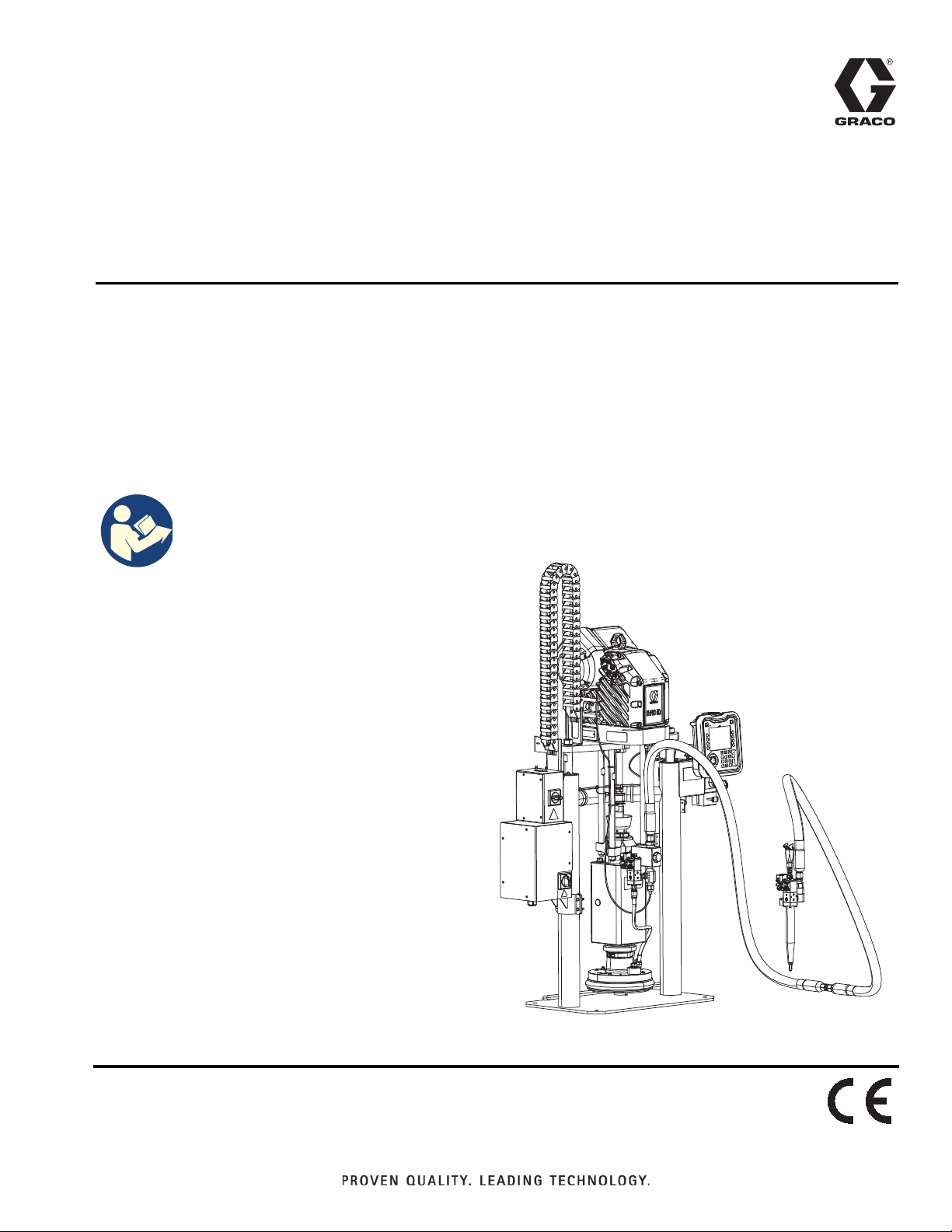
Operation
®
E-Flo
iQ Dispense
333587C
System
For dispensing and metering sealants, adhesives, and other medium to high viscosity
fluids. For professional use only.
Not approved for use in explosive atmospheres or hazardous (classified) locations.
See page 5 for system component information.
Important Safety Instructions
Read all warnings and instructions in this
manual and in all related manuals before
using the equipment. Save all
instructions.
EN
Page 2

Contents
Related Manuals . . . . . . . . . . . . . . . . . . . . . . . . . . . . 3
Dispense System Configurator . . . . . . . . . . . . . . . . 4
Dispense System Components. . . . . . . . . . . . . . . . 5
iQ Ram Supply Units . . . . . . . . . . . . . . . . . . . . . . 5
iQ Dispense Valves . . . . . . . . . . . . . . . . . . . . . . . 6
Hose Options . . . . . . . . . . . . . . . . . . . . . . . . . . . . 6
Dispense System Pressure . . . . . . . . . . . . . . . . . . . 7
Warnings . . . . . . . . . . . . . . . . . . . . . . . . . . . . . . . . . . 8
Dispense System Component Identification . . . . 11
Tandem Ram . . . . . . . . . . . . . . . . . . . . . . . . . . . 12
Supply Unit Component Identification . . . . . . . . . 13
iQ Ram Supply Unit . . . . . . . . . . . . . . . . . . . . . . 13
Power Disconnect . . . . . . . . . . . . . . . . . . . . . . . 14
Integrated Air Controls (AG) . . . . . . . . . . . . . . . 15
Integrated Air Line Accessories . . . . . . . . . . . . . 15
Advanced Display Module (ADM) . . . . . . . . . . . 16
ADM Display Details. . . . . . . . . . . . . . . . . . . . . . . . 17
ADM LED Status Descriptions . . . . . . . . . . . . . . 19
ADM Icons . . . . . . . . . . . . . . . . . . . . . . . . . . . . . 19
ADM Soft Keys. . . . . . . . . . . . . . . . . . . . . . . . . . 20
iQ Menu . . . . . . . . . . . . . . . . . . . . . . . . . . . . . . . . . . 22
Setup . . . . . . . . . . . . . . . . . . . . . . . . . . . . . . . . . . . . 23
System Setup Screen . . . . . . . . . . . . . . . . . . . . 23
Style Definitions . . . . . . . . . . . . . . . . . . . . . . . . . 24
Pump Settings . . . . . . . . . . . . . . . . . . . . . . . . . . 26
Heat Settings . . . . . . . . . . . . . . . . . . . . . . . . . . . 28
Advanced Setup. . . . . . . . . . . . . . . . . . . . . . . . . 31
Connect Light Tower Assembly . . . . . . . . . . . . . 33
Startup . . . . . . . . . . . . . . . . . . . . . . . . . . . . . . . . . . . 34
Flush the Pump . . . . . . . . . . . . . . . . . . . . . . . . . 34
Load Material . . . . . . . . . . . . . . . . . . . . . . . . . . . 35
Tandem Priming when Changing Drums . . . . . . 37
Operation. . . . . . . . . . . . . . . . . . . . . . . . . . . . . . . . . 38
Ram Run Screen . . . . . . . . . . . . . . . . . . . . . . . . 38
Tandem Run Screen . . . . . . . . . . . . . . . . . . . . . 39
Run Screen Editing Mode . . . . . . . . . . . . . . . . . 42
Heat Run Screen . . . . . . . . . . . . . . . . . . . . . . . . 42
Job Log . . . . . . . . . . . . . . . . . . . . . . . . . . . . . . . 44
Events and Errors . . . . . . . . . . . . . . . . . . . . . . . 45
Pressure Relief Procedure. . . . . . . . . . . . . . . . . . . 46
Shutdown the System . . . . . . . . . . . . . . . . . . . . . . 48
Maintenance . . . . . . . . . . . . . . . . . . . . . . . . . . . . . . 49
Pump Maintenance Screen 1. . . . . . . . . . . . . . . 49
Pump Maintenance Screen 2. . . . . . . . . . . . . . . 50
Diagnostics . . . . . . . . . . . . . . . . . . . . . . . . . . . . . . . 51
Pump Diagnostics Screen . . . . . . . . . . . . . . . . . 51
Heat Diagnostics Screen . . . . . . . . . . . . . . . . . . 51
Pressure Diagnostics Screen . . . . . . . . . . . . . . . 52
Troubleshooting . . . . . . . . . . . . . . . . . . . . . . . . . . . 53
View Errors . . . . . . . . . . . . . . . . . . . . . . . . . . . . . 53
Troubleshoot Errors . . . . . . . . . . . . . . . . . . . . . . 53
Error Codes . . . . . . . . . . . . . . . . . . . . . . . . . . . . 55
USB Data . . . . . . . . . . . . . . . . . . . . . . . . . . . . . . . . . 64
Download Procedure . . . . . . . . . . . . . . . . . . . . . 64
USB Logs . . . . . . . . . . . . . . . . . . . . . . . . . . . . . . 64
Event Log . . . . . . . . . . . . . . . . . . . . . . . . . . . . . . 64
Job Log. . . . . . . . . . . . . . . . . . . . . . . . . . . . . . . . 65
Automation Log . . . . . . . . . . . . . . . . . . . . . . . . . 65
System Configuration Settings . . . . . . . . . . . . . . 65
Custom Language File . . . . . . . . . . . . . . . . . . . . 65
Create Custom Language Strings . . . . . . . . . . . 66
Upload Procedure. . . . . . . . . . . . . . . . . . . . . . . . 66
Integration . . . . . . . . . . . . . . . . . . . . . . . . . . . . . . . . 67
Discrete Inputs/Outputs . . . . . . . . . . . . . . . . . . . 67
Job Cycle Timing Diagram . . . . . . . . . . . . . . . . . 69
Discrete Timing Diagram . . . . . . . . . . . . . . . . . . 70
Communications Gateway Module (CGM). . . . . 71
Prime Diagram . . . . . . . . . . . . . . . . . . . . . . . . . . 87
Depressurize Diagram . . . . . . . . . . . . . . . . . . . . 87
System Enable - Remote Start Diagram . . . . . . 88
Acknowledge - Clear Error Diagram. . . . . . . . . . 88
Manual Crossover Diagram . . . . . . . . . . . . . . . . 89
Data Exchange Diagram . . . . . . . . . . . . . . . . . . 89
Power Reset Diagram . . . . . . . . . . . . . . . . . . . . 90
Heat CGM Timing Diagram . . . . . . . . . . . . . . . . 90
Heat Module Acknowledge-Clear Error Diagram 91
Heat Zone Acknowledge-Clear Error Diagram . . 91
Heat CGM Data Exchange Diagram . . . . . . . . . 92
Connection Details . . . . . . . . . . . . . . . . . . . . . . . 93
Gateway Setup Screens . . . . . . . . . . . . . . . . . . . 96
Integration Feedback Screens . . . . . . . . . . . . . . 99
Technical Specifications . . . . . . . . . . . . . . . . . . . 100
Recycling and Disposal . . . . . . . . . . . . . . . . . . . . 101
End of Product Life . . . . . . . . . . . . . . . . . . . . . . 101
California Proposition 65 . . . . . . . . . . . . . . . . . . . 101
Graco Standard Warranty . . . . . . . . . . . . . . . . . . 102
2 333587C
Page 3

Related Manuals
Related manuals in English:
Manual Description
333585 iQ Dispense Valves, Instructions-Parts
333586 E-Flo iQ Dispense System, Installation-Parts
3A6321 ADM Token In-System Programming
312493 Light Tower Kit Instructions
3A1244 Graco Control Architecture Module
3A6482 APD20 Advanced Precision Driver
313138 Supply System Communications Gateway
Module Installation Kit
Related Manuals
333587C 3
Page 4

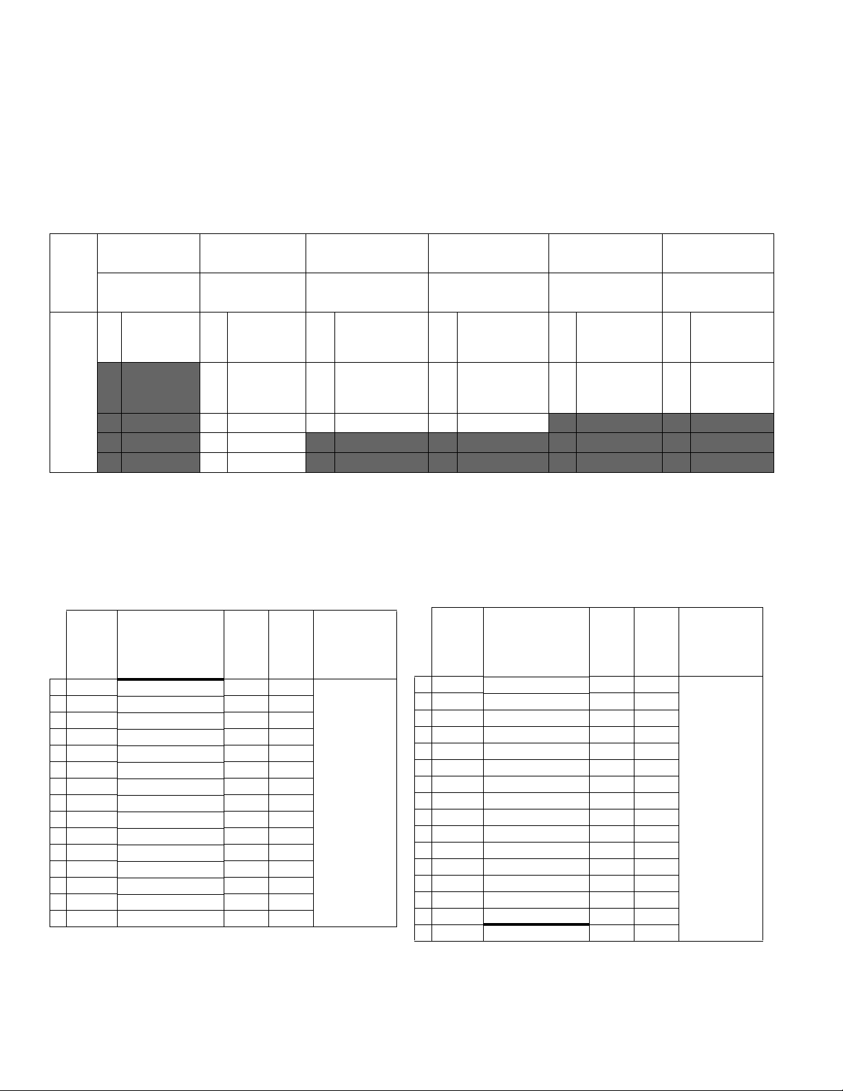
Dispense System Configurator
Dispense System Configurator
The E-Flo iQ dispense system provides the flexibility to configure a complete system to meet your specific needs.
This includes offering multiple combinations of the following components:
• iQ Ram Supply Units
• iQ Dispense Valves
• Hoses and connectors
For dispense system component information, see Dispense System Components on page 5.
First,
Second
and
Third
Digit
EQC
E-Flo iQ
System
Fourth
Digit
Revision
Fifth
Digit Sixth Digit
Seventh
Digit
Platen
Single or
Tandem
S Single H Heated Y Yes
T Tan-
dem
Heat
Option
A Ambient
Valve
Option
Eighth Digit
Ram Supply Unit Options
Size
A 3 in.
B 3 in.
C 3 in.
D 3 in.
F 3 in.
G 3 in.
H 3 in.
J 3 in.
K 6.5 in.
M 6.5 in.
N 6.5 in.
P 6.5 in.
Drum
Size
20 L
(5 Gal) CS EPDM
20 L
(5 Gal) CS
20 L
(5 Gal) CM EPDM
20 L
(5 Gal) CM
200 L
(55 Gal) CS EPDM
200 L
(55 Gal) CS
200 L
(55 Gal) CM EPDM
200 L
(55 Gal) CM
200 L
(55 Gal) CS EPDM
200 L
(55 Gal) CS
200 L
(55 Gal) CM EPDM
200 L
(55 Gal) CM
Pump
Material
Seal
Material
Neo-
prene
Neo-
prene
Neo-
prene
Neo-
prene
Neo-
prene
Neo-
prene
Ninth Digit
Fieldbus
Option
A Ether-
Net/IP
B PROF-
INET
C PROFI-
BUS
D Devi-
ceNet
N None
Digits Ten
through
Seventeen
Hose
Options for
Tandem
Hoses (Dig-
its 10-13)
and Supply
Hoses (Dig-
its 14-17)
(See Hose
Options on
page 6)
Digits
Eighteen
through
Twenty Seven
Valve Options
(See the iQ
Dispense
Valves Instruc-
tions - Parts
manual for
valve model
options)
KEY:
CS = Carbon Steel Severe Duty
CM = Carbon Steel MaxLife
®
®
4 333587C
Page 5

Dispense System Components
Dispense System Components
NOTE: The Heated option for the E-Flo iQ system is for warm melt applications with a maximum temperature of 70° C
(158° F).
iQ Ram Supply Units
Check the identification plate (ID) on the back of the ram post near the Power Junction Box (AJ) for the seven-digit part
number of the iQ ram supply unit. Use the following matrix to define the construction of the unit, based on the seven digits.
For example, Part No. EZC2422 represents an electric supply unit (EZ), a carbon steel Check-Mate 200 Severe Duty dis-
placement pump (C2), a 3 in. ram (4), a 5-gallon platen with a neoprene seal (2), and an ADM (2).
The digits in the following matrix do not correspond to the reference numbers in the Parts drawings and lists.
EZ C2 4
First
and
Second
Digit
EZ
(Electric
Supply
System)
Third and Fourth Digit Fifth Digit
Check-Mate Pump Options Ram Options
Pump
Size
Material
C1 200cc CS Ambient
C2 200cc CS Heated
C3 200cc CM Ambient
C4 200cc CM Heated
Heated/
Ambient
<70° C 2 D200 3 in.
<70° C 4 D60 3 in.
Name Size
1 D60 3 in.
3 D200s 6.5 in.
5 D200 3 in.
6 D200s 6.5 in.
Drum
Size Style
20 L
(5 Gal) Ambient 1
200 L
(55 Gal) Ambient 2
200 L
(55 Gal) Ambient 3
Heated
20 L
(5 Gal)
200 L
(55 Gal)
200 L
(55 Gal)
<70° C 4
Heated
<70° C 5
Heated
<70° C 6
Sixth Digit
Platen and Seal Options
Platen
(5 Gal) CST/AL Neoprene
(5 Gal) CST/AL Neoprene
(5 Gal) CST/AL EPDM
(5 Gal) CST/AL EPDM
200 L
200 L
200 L
7
200 L
8
Platen
Size
Material
20 L
20 L
20 L
20 L
(55
Gal) AL Neoprene
(55
Gal) AL Neoprene
(55
Gal) AL EPDM
(55
Gal) AL EPDM
Material Wiper
22
Seventh
Digit
Interface
Options
Seal
Single
Single
Single
Single
Double
Double
Double
Double
Heated/
Ambient Interface
Ring Ambient 2 ADM
Heated
Ring
Ring Ambient
Ring
Ring Ambient
Ring
Ring Ambient
Ring
<70° C 4No ADM
Heated
<70° C
Heated
<70° C
Heated
<70° C
KEY:
CS = Carbon Steel Severe Duty
CM = Carbon Steel MaxLife
CST/AL = Carbon Steel/Aluminum
AL = Aluminum
333587C 5
Page 6
Dispense System Components
iQ Dispense Valves
Check the identification plate on the valve for the ten-digit part number of the iQ dispense valve. Use the following
matrix to define the construction of the valve, based on the ten digits. For example, Part No. V25AB060BA
represents a valve (V) with 1/4 in. NPT inlet ports (25), NPT tip (A), ball/seat type (B), 60 mm outlet block length
(060), solenoid (B), with no heat (A).
First
Digit
Second and
Third Digit
Fourth Digit Fifth Digit
Size Tip Size Type
Sixth, Seventh,
and Eighth Digit
Outlet Block
Length
Ninth Digit Tenth Digit
Action Heat
Valve
25
1/4 in. NPT
A 1/4 in. NPT B Ball/Seat 000 NA B
Mounted
A None
Solenoid
60 mm
V
C 0.6 mm S Snuff-Back 060
D
*Remote
Solenoid
B Heated
Block
D 1.0 mm T Tip Seal 200
200 mm
F 1.3 mm
G 1.7 mm
* Remote solenoid supplied by customer.
NOTE: Refer to the iQ Dispense Valves Instructions-Parts manual for additional information about iQ Dispense
Valves. See Related Manuals on page 3
Hose Options
Working
Pressure
Temperature
Rating
4000 psi (28
MPa, 276 bar) at
-65° F - 400° F
(101° C - 204°
Part No. JIC Dash Size Length Heat
04 19M404 -10 (5/8 in, 15.9 mm) 6 ft Heated
05 19M405 -10 (5/8 in, 15.9 mm) 10 ft Heated
06 19M406 -10 (5/8 in, 15.9 mm) 15 ft Heated
07 19M407 -10 (5/8 in, 15.9 mm) 20 ft Heated
08 19M408 -10 (5/8 in, 15.9 mm) 25 ft Heated
11 19M411 -12 (3/4 in, 19.0 mm) 6 ft Heated
12 19M412 -12 (3/4 in, 19.0 mm) 10 ft Heated
13 19M413 -12 (3/4 in, 19.0 mm) 15 ft Heated
14 19M414 -12 (3/4 in, 19.0 mm) 20 ft Heated
15 19M415 -12 (3/4 in, 19.0 mm) 25 ft Heated
16 19M416 -16 (1 in, 25.4 mm) 6 ft Heated
17 19M417 -16 (1 in, 25.4 mm) 10 ft Heated
18 19M418 -16 (1 in, 25.4 mm) 15 ft Heated
19 19M419 -16 (1 in, 25.4 mm) 20 ft Heated
20 19M420 -16 (1 in, 25.4 mm) 25 ft Heated
Working
Pressure
Temperature
Rating
4000 psi (28
MPa, 276 bar) at
-65° F - 212° F
(-54° C - 100°
C)
3000 psi (21
MPa, 207 bar) at
213° F - 400° F
(101° C - 204°
C)
Part No. JIC Dash Size Length Heat
65 17K265 -10 (5/8 in, 15.9 mm) 6 ft Ambient
66 17K266 -10 (5/8 in, 15.9 mm) 10 ft Ambient
67 17K267 -10 (5/8 in, 15.9 mm) 15 ft Ambient
68 17K268 -10 (5/8 in, 15.9 mm) 20 ft Ambient
69 17K269 -10 (5/8 in, 15.9 mm) 25 ft Ambient
72 17K272 -12 (3/4 in, 19.0 mm) 6 ft Ambient
73 17K273 -12 (3/4 in, 19.0 mm) 10 ft Ambient
74 17K274 -12 (3/4 in, 19.0 mm) 15 ft Ambient
75 17K275 -12 (3/4 in, 19.0 mm) 20 ft Ambient
76 17K276 -12 (3/4 in, 19.0 mm) 25 ft Ambient
77 17K277 -16 (1 in, 25.4 mm) 6 ft Ambient
78 17K278 -16 (1 in, 25.4 mm) 10 ft Ambient
79 17K279 -16 (1 in, 25.4 mm) 15 ft Ambient
80 17K280 -16 (1 in, 25.4 mm) 20 ft Ambient
81 17K281 -16 (1 in, 25.4 mm) 25 ft Ambient
00 No Hose N/A N/A N/A
C)
6 333587C
Page 7

Dispense System Pressure
Due to factors such as the dispense system design, the
material being pumped, and the flow rate, the dynamic
pressure will not reach the rated working (stall) pressure
of the system.
Pump Working (Stall) Pressure Max Dynamic (Run) Pressure
Lower Size psi bar MPa psi bar MPa
Dispense System Pressure
Check-Mate
200CS/CM
4,000 290 29.0 3,905 269 26.9
333587C 7
Page 8
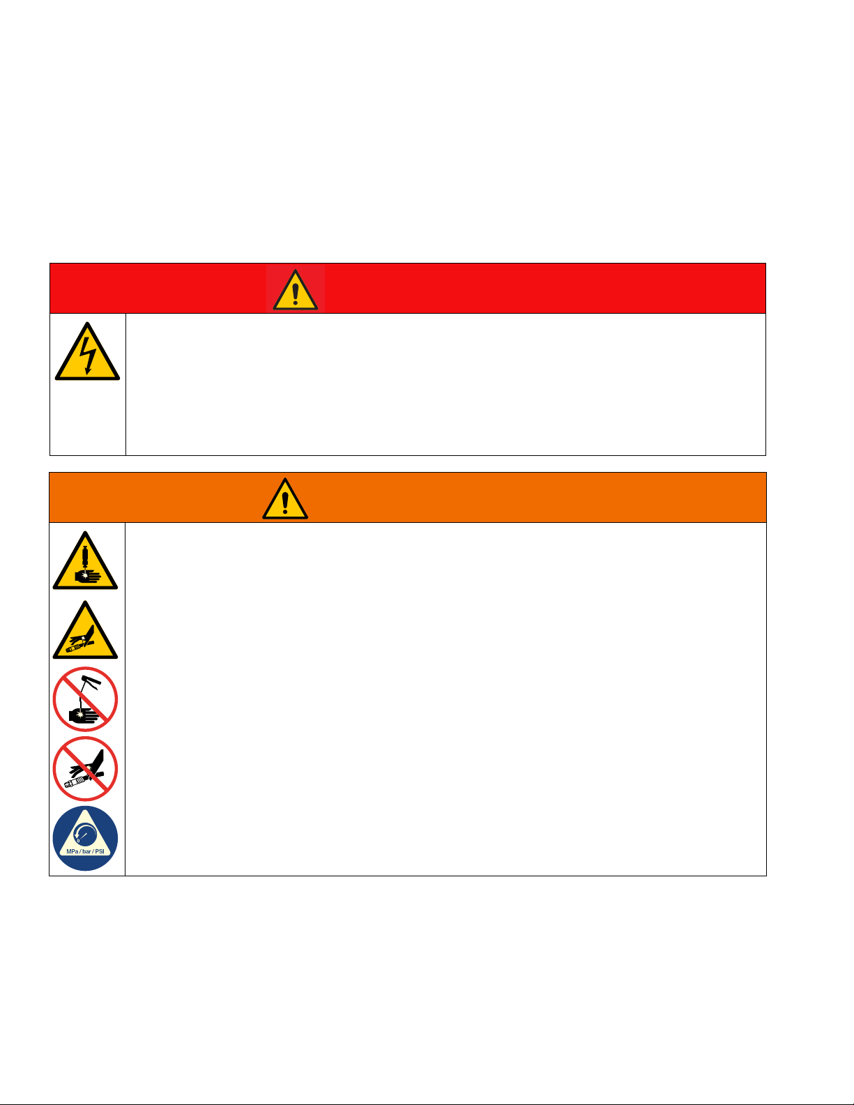
Warnings
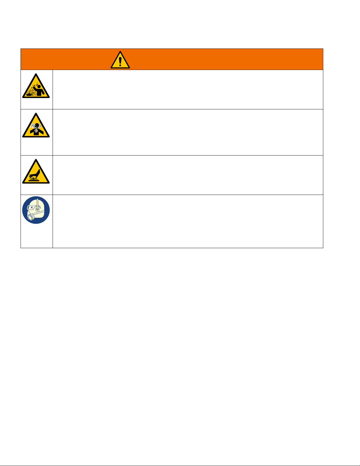
DANGER
WARNING
Warnings
The following warnings are for the setup, use, grounding, maintenance, and repair of this equipment. The
exclamation point symbol alerts you to a general warning and the hazard symbols refer to procedure-specific risks.
When these symbols appear in the body of this manual or on warning labels, refer back to these Warnings.
Product-specific hazard symbols and warnings not covered in this section may appear throughout the body of this
manual where applicable.
SEVERE ELECTRIC SHOCK HAZARD
This equipment can be powered by more than 240 V. Contact with this voltage will cause death or
serious injury.
• Turn off and disconnect power at main switch before disconnecting any cables and before servicing
equipment.
• This equipment must be grounded. Connect only to grounded power source.
• All electrical wiring must be done by a qualified electrician and comply with all local codes and
regulations.
SKIN INJECTION HAZARD
High-pressure fluid from dispensing device, hose leaks, or ruptured components will pierce skin. This
may look like just a cut, but it is a serious injury that can result in amputation. Get immediate surgical
treatment.
• Do not point dispensing device at anyone or at any part of the body.
• Do not put your hand over the fluid outlet.
• Do not stop or deflect leaks with your hand, body, glove, or rag.
• Follow the Pressure Relief Procedure when you stop dispensing and before cleaning, checking, or
servicing equipment.
• Tighten all fluid connections before operating the equipment.
• Check hoses and couplings daily. Replace worn or damaged parts immediately.
8 333587C
Page 9
Warnings
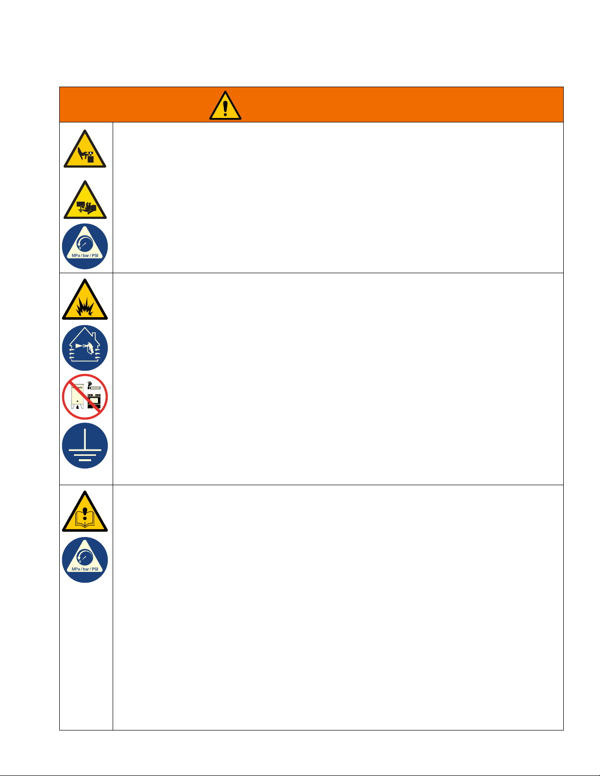
WARNING
MOVING PARTS HAZARD
Moving parts can pinch, cut or amputate fingers and other body parts.
• Keep clear of moving parts.
• Do not operate equipment with protective guards or covers removed.
• Equipment can start without warning. Before checking, moving, or servicing equipment, follow the
Pressure Relief Procedure and disconnect all power sources.
FIRE AND EXPLOSION HAZARD
Flammable fumes, such as solvent and paint fumes, in work area can ignite or explode. Paint or solvent
flowing through the equipment can cause static sparking. To help prevent fire and explosion:
• Use equipment only in well-ventilated area.
• Eliminate all ignition sources; such as pilot lights, cigarettes, portable electric lamps, and plastic drop
cloths (potential static sparking).
• Ground all equipment in the work area. See Grounding instructions.
• Never spray or flush solvent at high pressure.
• Keep work area free of debris, including solvent, rags and gasoline.
• Do not plug or unplug power cords, or turn power or light switches on or off when flammable fumes
are present.
• Use only grounded hoses.
• Hold gun firmly to side of grounded pail when triggering into pail. Do not use pail liners unless they
are anti-static or conductive.
• Stop operation immediately if static sparking occurs or you feel a shock. Do not use equipment until
you identify and correct the problem.
• Keep a working fire extinguisher in the work area.
EQUIPMENT MISUSE HAZARD
Misuse can cause death or serious injury.
• Do not operate the unit when fatigued or under the influence of drugs or alcohol.
• Do not exceed the maximum working pressure or temperature rating of the lowest rated system
component. See Technical Specifications in all equipment manuals.
• Use fluids and solvents that are compatible with equipment wetted parts. See Technical
Specifications in all equipment manuals. Read fluid and solvent manufacturer’s warnings. For
complete information about your material, request Safety Data Sheets (SDSs) from distributor or
retailer.
• Turn off all equipment and follow the Pressure Relief Procedure when equipment is not in use.
• Check equipment daily. Repair or replace worn or damaged parts immediately with genuine
manufacturer’s replacement parts only.
• Do not alter or modify equipment. Alterations or modifications may void agency approvals and create
safety hazards.
• Make sure all equipment is rated and approved for the environment in which you are using it.
• Use equipment only for its intended purpose. Call your distributor for information.
• Route hoses and cables away from traffic areas, sharp edges, moving parts, and hot surfaces.
• Do not kink or over bend hoses or use hoses to pull equipment.
• Keep children and animals away from work area.
• Comply with all applicable safety regulations.
333587C 9
Page 10
Warnings
WARNING
SPLATTER HAZARD
Hot or toxic fluid can cause serious injury if splashed in the eyes or on skin. During blow off of platen,
splatter may occur.
• Use minimum air pressure when removing platen from drum.
TOXIC FLUID OR FUMES HAZARD
Toxic fluids or fumes can cause serious injury or death if splashed in the eyes or on skin, inhaled, or
swallowed.
• Read Safety Data Sheets (SDSs) to know the specific hazards of the fluids you are using.
• Store hazardous fluid in approved containers, and dispose of it according to applicable guidelines.
BURN HAZARD
Equipment surfaces and fluid that is heated can become very hot during operation. To avoid severe
burns:
• Do not touch hot fluid or equipment.
PERSONAL PROTECTIVE EQUIPMENT
Wear appropriate protective equipment when in the work area to help prevent serious injury, including
eye injury, hearing loss, inhalation of toxic fumes, and burns. Protective equipment includes but is not
limited to:
• Protective eyewear, and hearing protection.
• Respirators, protective clothing, and gloves as recommended by the fluid and solvent manufacturer.
10 333587C
Page 11
Dispense System Component Identification
A
B
C
D
E
H
G
J
F
*Circular
Electrical
Connection
*Square
Electrical
Connection
*Circular
Electrical
Connection
*Square
Electrical
Connection
Dispense System Component Identification
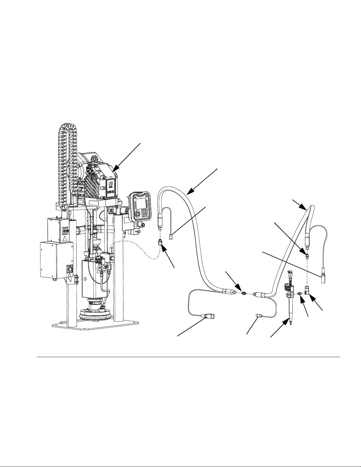
NOTE: Figure 1 shows a typical E-Flo iQ dispense
system installation with an iQ ram supply unit, hoses,
connectors, and an iQ dispense valve. Some
installations may require only one hose depending on
the needs of the system.
FIG. 1: E-Flo iQ Dispense System
Key:
A iQ Ram Supply Unit
B iQ Dispense Valve
C First Hose from Supply System
D Second Hose to iQ Dispense Valve
E Ram Supply System Fitting to First Hose
F First Hose Fitting to Second Hose
G Second Hose Fitting to Swivel
H Swivel Fitting
J Swivel to Valve Fitting
* Applies to heated hoses only.
333587C 11
Page 12
Dispense System Component Identification
A
B
M
D
F
G
H
J
K
L
R
C
E
N
P
*Circular
Electrical
Connection
*Square
Electrical
Connection
*Circular
Electrical
Connection
*Square
Electrical
Connection
*Circular
Electrical
Connection
S
S
Tandem Ram
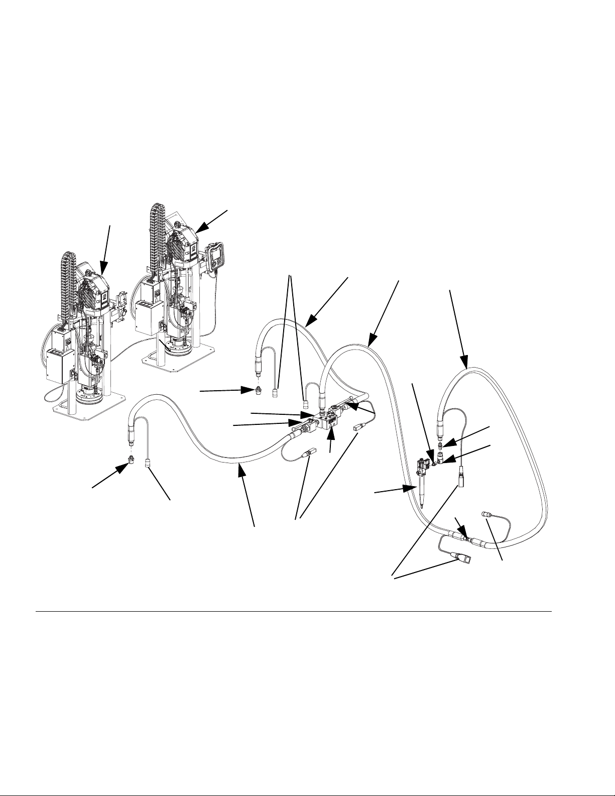
NOTE: FIG. 2 shows a typical E-Flo iQ dispense system
installation with a Tandem iQ ram supply unit, hoses,
connectors, and an iQ dispense valve. Some
installations may not require Supply Hose 2 (D) to iQ
Dispense Valve (B) depending on the needs of the
system.
FIG. 2: Tandem E-Flo iQ Dispense System
Key:
A iQ Ram Supply Unit 1
B iQ Dispense Valve
C Supply Hose 1
D Supply Hose 2
E Tandem Block Fitting to Supply Hose 1
F Supply Hose 1 Fitting to Supply Hose 2
G Supply Hose 2 Fitting to Swivel
H Swivel Fitting
J Swivel Fitting to Valve
K iQ Ram Supply Unit 2
L Tandem Hose 1
M Tandem Hose 2
N Ram Supply Unit 1 Fitting to Tandem Hose 1
P Ram Supply Unit 2 Fitting to Tandem Hose 2
R Tandem Block
S Ball Valves
* Applies to heated hoses only.
12 333587C
Page 13
Supply Unit Component Identification
AU
AT
AS
AA
ZC
AV
AF
AG
AR
AN
AM
AD
AJ
AK
*AX
AL
*ZA
AZ
AY
AC
AE
AW
ZB
Ambient System
AZ
Heated System
AZ
AK
AH
AB
iQ Ram Supply Unit
D200 3 in. Dual Post Shown
Supply Unit Component Identification
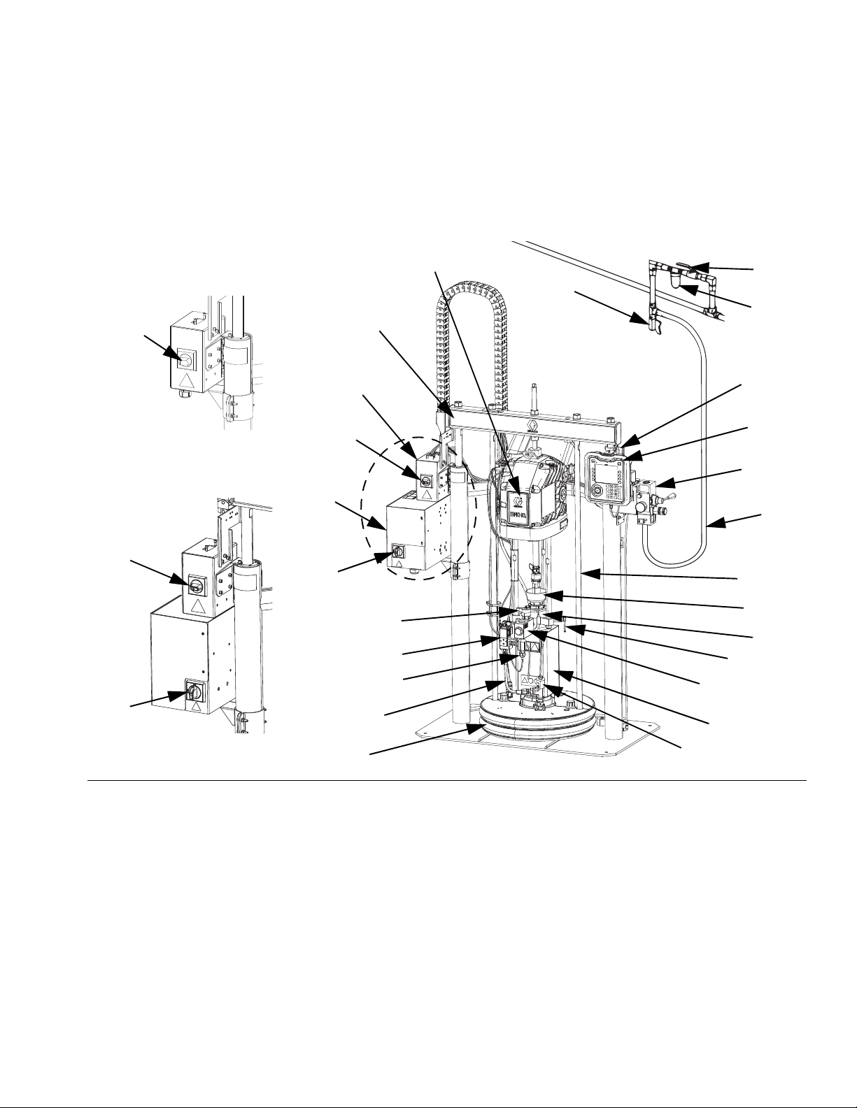
FIG. 3: iQ Ram Supply Unit
Key:
AA Ram Assembly
AB Electric Driver
AC Displacement Pump
AD Platen
AE Fluid Check Valve
AF Advanced Display Module (ADM)
AG Integrated Air Controls (see Figure 6)
AH Platen Bleed Port
AJ Power Junction Box
AK Power Junction Box Switch
AL Platen Lift Rod
AM Pump Bleed Valve
AN Wet Cup
333587C 13
AR Air Line (not supplied)
AS Air Line Drain Valve (not supplied)
AT Air Filter (not supplied)
AU Bleed Type Air Shutoff Valve (required) (not supplied)
AV Level Sensors
AW Outlet Pressure Transducer
AX *Heat Control Box
AY Platen Valve Kit (optional)
AZ Disconnect Switch (See Power Disconnect on page 14)
ZA *Pump Heater
ZB Recirculation Hose
ZC Pump Relief Valve
* Parts on heated systems only.
Page 14
Supply Unit Component Identification
AK
AZ
Heated System
AZ
Ambient System
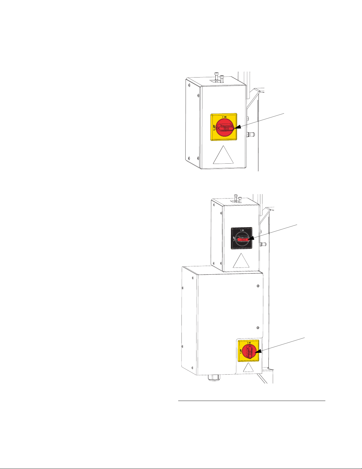
Power Disconnect
Every E-Flo iQ Dispense System has a red and yellow
Disconnect Switch which shuts off power to the entire
system. The location of the switch is different for
ambient and heated systems. See Figure 4.
On ambient systems, the Disconnect Switch (AZ) is
located on the Power Junction Box (AJ).
On heated systems, the Disconnect Switch (AZ) is
located on the Heat Control Box (AX). Heated systems
also have a red and black Power Junction Box Switch
(AK) located on the Power Junction Box (AJ). The Power
Junction Box Switch (AK) removes power to everything
EXCEPT heat. The Disconnect Switch (AZ) removes
power to the entire system, including heat.
F
IG
. 4. Power Disconnect
14 333587C
Page 15
Supply Unit Component Identification
BA
BB
BC
BE
BD
BD
1/4 NPT
Plug
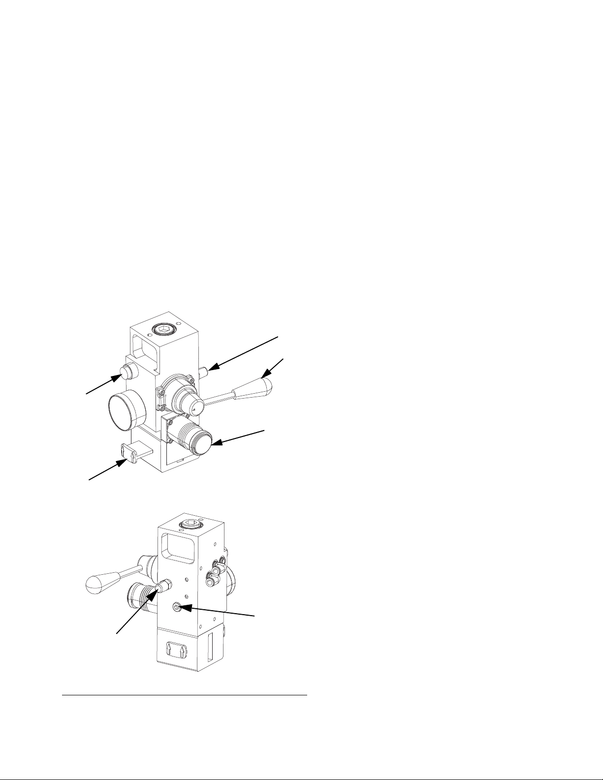
Integrated Air Controls (AG)
The integrated air controls include:
• Main Air Slider Valve (BA): turns air on and off to
the system. When closed, the valve relieves pres-
sure downstream.
• Ram Air Regulator (BB): controls Ram up and
down pressure and blowoff pressure.
• Ram Director Valve (BC): controls Ram direction.
• Exhaust Port with Muffler (BD)
• Blowoff Button (BE): turns air on and off to push
the Platen (D) out of an empty drum.
Integrated Air Line Accessories
See Figure 3.
• Air Line Drain Valve (AS): removes condensed
water from the air line. Not supplied.
• Air Line Filter (AT): removes harmful dirt and mois-
ture from the compressed air supply. Not supplied.
• Second Bleed-type Air Valve (AU) (required): iso-
lates Air Line accessories for servicing. Locate
upstream from all other Air Line accessories. Not
supplied.
F
IG
. 5. Integrated Air Control Module
333587C 15
Page 16
Supply Unit Component Identification
CA
CB
CC
CD
CE
CF
CG
CH
CP
CK
CN
CM
CL
CJ
CR
CS
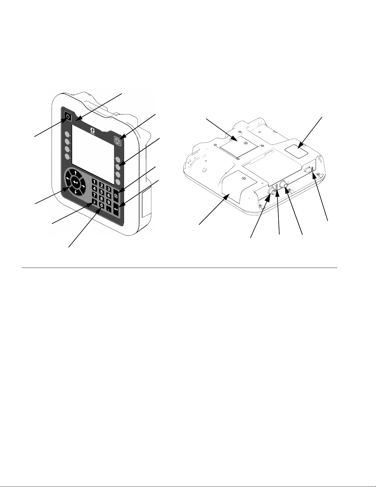
Advanced Display Module (ADM)
Front and Rear Views
FIG. 6: ADM Component Identification
Key:
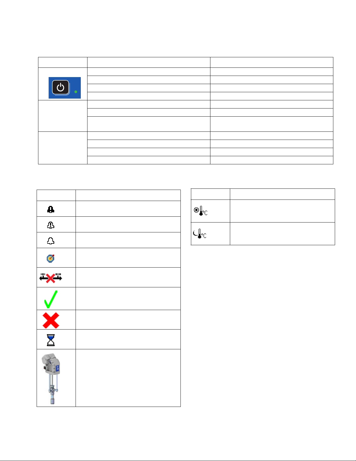
CA Startup/Shutdown
Starts up or shuts down the system. Toggles
between Active and Inactive system.
CB System Status Indicator LED
CC Pump Soft Stop
Stops all pump processes and disables the pump.
Also stops all heating processes and disables the
heat. This is not a safety or emergency stop.
CD Soft Keys
Defined by the icon on the screen next to the soft
key. Performs the specific operation for that icon
when pressed.
CE Cancel
Cancels a selection or number entry while in the
process of entering a number or making a selection.
Cancels the pump processes. Exits a screen
without saving changes.
CF Enter
Select to update a field, accept a selection or value,
acknowledge an event, enter a screen, and toggle
selected items.
CG Lock/Setup
Toggles between Run screens and the iQ Menu.
CH Directional Keypad
Navigate within a screen or to a new screen.
CJ Numeric Keypad
Input numeric values.
CK Part Number Identification Label
CL USB Interface
CM CAN Cable Connection
Power and communication.
CN Module Status LEDs
Visual indicators to show the status of the ADM.
CP Token Access Cover
Access cover for blue software token.
CR Battery Access Cover
CS Light Tower Connection
NOTE: If using a Tandem system, the AMD is only
included with the iQ Ram Supply Unit 1 (A)
16 333587C
Page 17
ADM Display Details
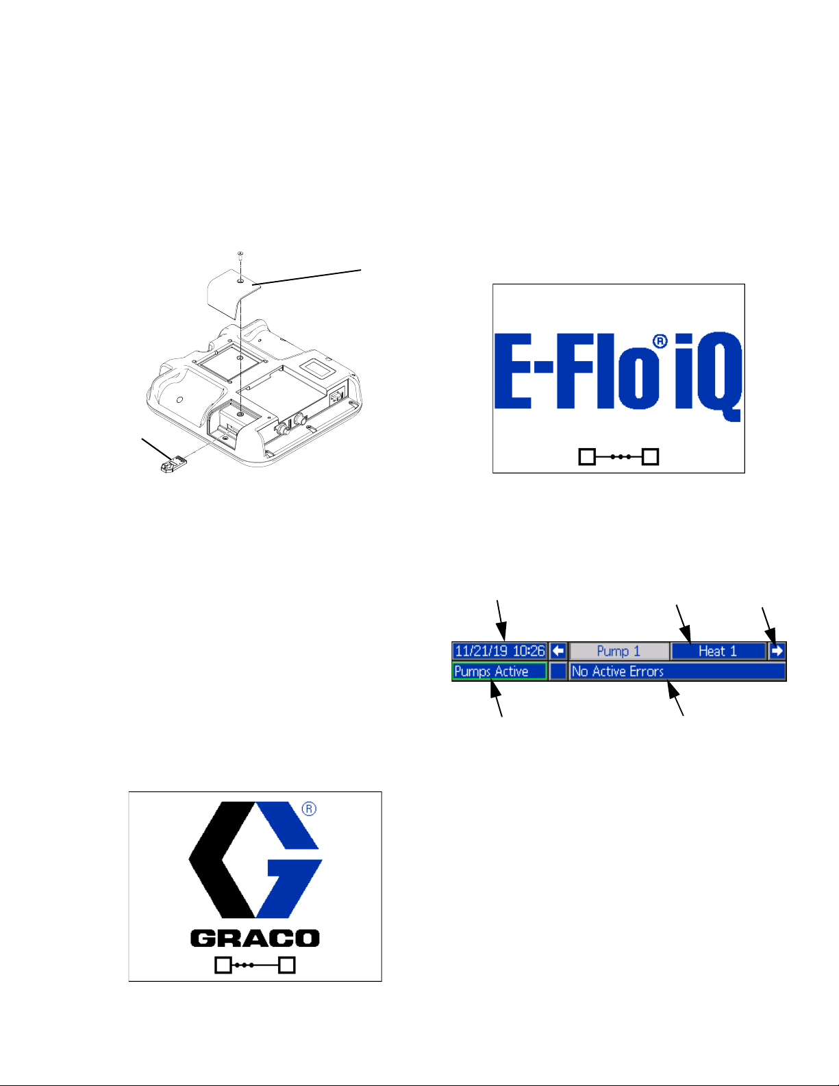
CP
Blue Token
Date and Time
Navigation
Arrows
Screen Menu
Status
System Mode
ADM Display Details
Use the Blue Token
The E-Flo iQ system includes a blue token that must be
inserted into the ADM to initiate the E-Flo iQ software.
1. Remove the ADM from the bracket.
2. Use a hex wrench to remove the screws from the
token access cover (CP).
Five seconds after the E-Flo iQ blue token is inserted
into the ADM, the Graco power up screen switches to
the E-Flo iQ power up screen. This screen remains on
while the ADM runs through initialization and
establishes communication with other modules in the
system.
Menu Bar
The Menu Bar appears at the top of each screen (the
following image is only an example).
3. Remove the access cover (CP).
4. Insert and press the blue software token firmly into
the slot.
5. Replace the token access cover (CP) and insert and
tighten the screw that holds it in place.
6. Mount the ADM on the bracket.
Power Up Screen
This screen appears when the ADM is powered up.
Date and Time
The date and time are always displayed in one of the
following formats. The time is always displayed as a
24-hour clock.
•
DD/MM/YY HH:MM
•
YY/MM/DD HH:MM
•
MM/DD/YY HH:MM
Navigation Arrows
The left and right arrows are only visible when screen
navigation is allowed.
333587C 17
Page 18
ADM Display Details
Screen Menu
The screen menu indicates the currently active screen,
which is highlighted. It also indicates the associated
screens that are available by scrolling left and right.
System Mode
The current system mode is displayed in the lower left of
the Menu Bar. System modes include: Pump Active,
Pump Inactive, Job in Cycle, Pre-charge, Heat Inactive,
Heat Off, Heat Soak, Heat at Temp, Heat in Setback.
Status
The current system status is displayed in the lower right
of the Menu Bar.
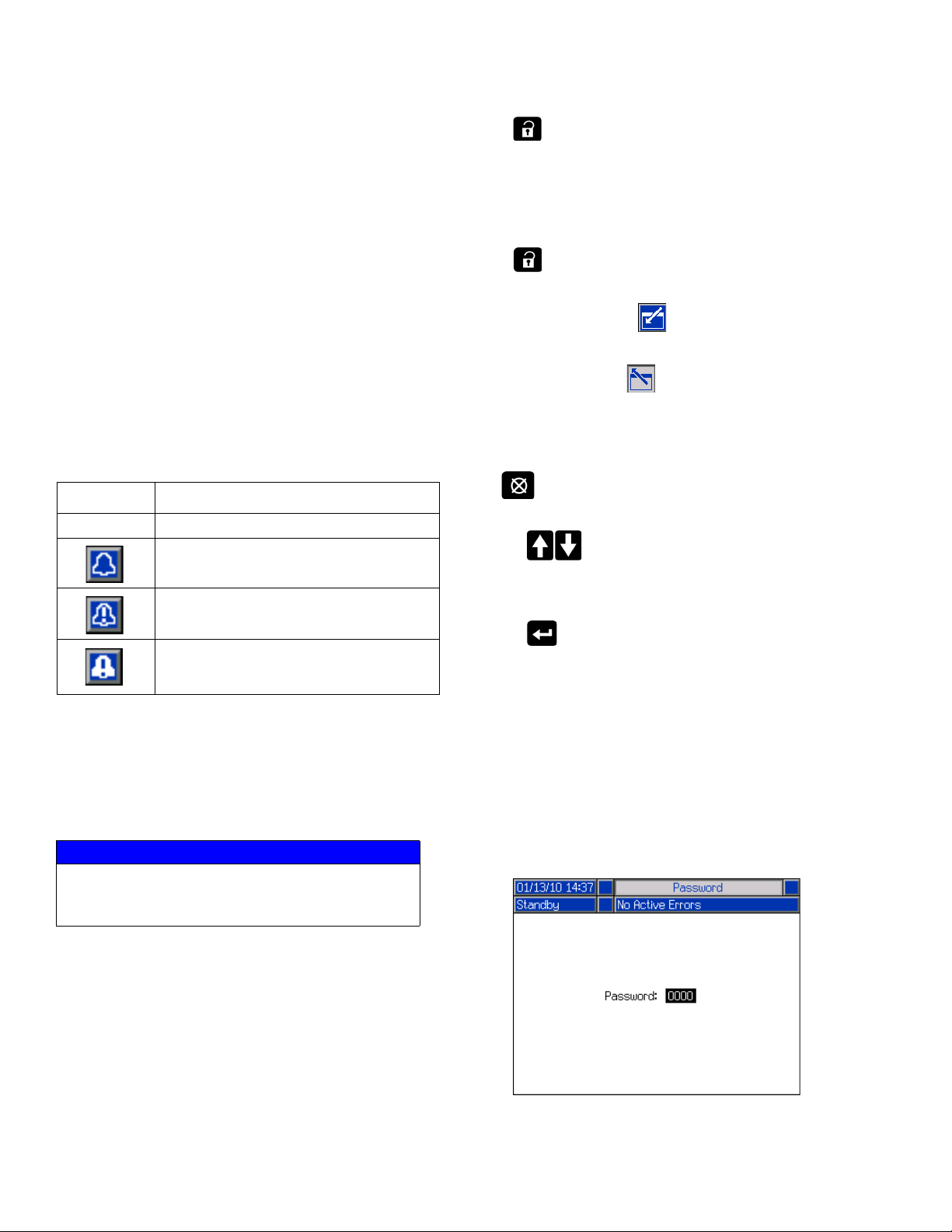
Alarm/Deviation
The current system error is displayed in the middle of
the Menu Bar. There are four possibilities.
Icon Function
No Icon No information or no error has occurred
Advisory
Deviation
Press on any Run screen to switch to the iQ Menu
screens. If the system has a password lock, the
Password screen is displayed. If the system is not
locked (password is set to 0000), iQ Menu Screen 1 is
displayed. Refer to iQ Menu on page 22 for additional
information.
Press on any Setup screen to return to the Run
screen.
Press the Enter soft key to activate the editing
function on any screen.
Press the Exit soft key to exit the editing function
and save any changes.
Use the other soft keys to select the function adjacent to
them.
Use to exit a screen. Using this key while in editing
mode will exit the screen without saving changes.
Use the keys on the ADM to move through the
settings on a screen or drop down menu and to scroll
through multiple screens on the right side of the display.
Alarm
Soft Keys
Icons next to the soft keys indicate which mode or action
is associated with each soft key. Soft keys that do not
have an icon next to them are not active in the current
screen. See Advanced Display Module on page 16
and ADM Soft Keys on page 20.
NOTICE
To prevent damage to the soft key buttons, do not
press buttons with sharp objects such as pens,
plastic cards, or fingernails.
Navigating the Screens
There are two types of screens:
Run screens control operations and display system
status and data.
Setup screens control system parameters and
advanced features. These screens are accessed
through the iQ Menu.
Use the key to choose a field to update, to make a
selection, to save a selection or value, to enter a screen,
or to acknowledge an event.
Set Password
You can set a password to protect access to some
selections on the iQ Menu screens. See iQ Menu on
page 22. It can also be used when changing from
Remote to Local control mode to protect against
inadvertently changing control modes. To set or remove
the password, select Advanced from iQ Menu 2. See
Advanced Setup Screen 1 on page 31.
18 333587C
Page 19
ADM LED Status Descriptions
LED Conditions Description
System Status Green Solid Run Mode, System On
Green Flashing Setup Mode, System On
Yellow Solid Run Mode, System Off
Yellow Flashing Setup Mode, System Off
USB Status (CL) Green Flashing Data recording in progress
Yellow Solid Downloading information to USB
Green and Yellow Flashing ADM is busy, USB cannot transfer information
when in this mode
ADM Status (CN) Green Solid Power applied to module
Yellow Flashing Active Communication
Red Steady Flashing Software upload from token in progress
Red Random Flashing or Solid Module error exists
ADM Icons
ADM Display Details
Icon Function
Alarm - See Troubleshooting, page 53
for more information.
Deviation - See Troubleshooting, page
53 for more information.
Advisory - See Troubleshooting, page
53 for more information.
Target for primary pressure and flow.
Only displayed in priming mode.
Communication Error
No issues found with parameter or
setting value
Missing or unexpected parameter or
setting value
System is processing request
(animated)
Pump position (animated). The pump
coupler will move up and down in real
time and indicate the approximate
position of the pump. The pump will
need to complete one full down stroke
upon each power cycle before the
position is valid.
Icon Function
Zone setpoint temperature showing the
temperature the zone heats too when
the heat is turned on.
Zone setback temperature showing the
setback the zone goes to when the heat
is in setback mode.
333587C 19
Page 20
ADM Display Details
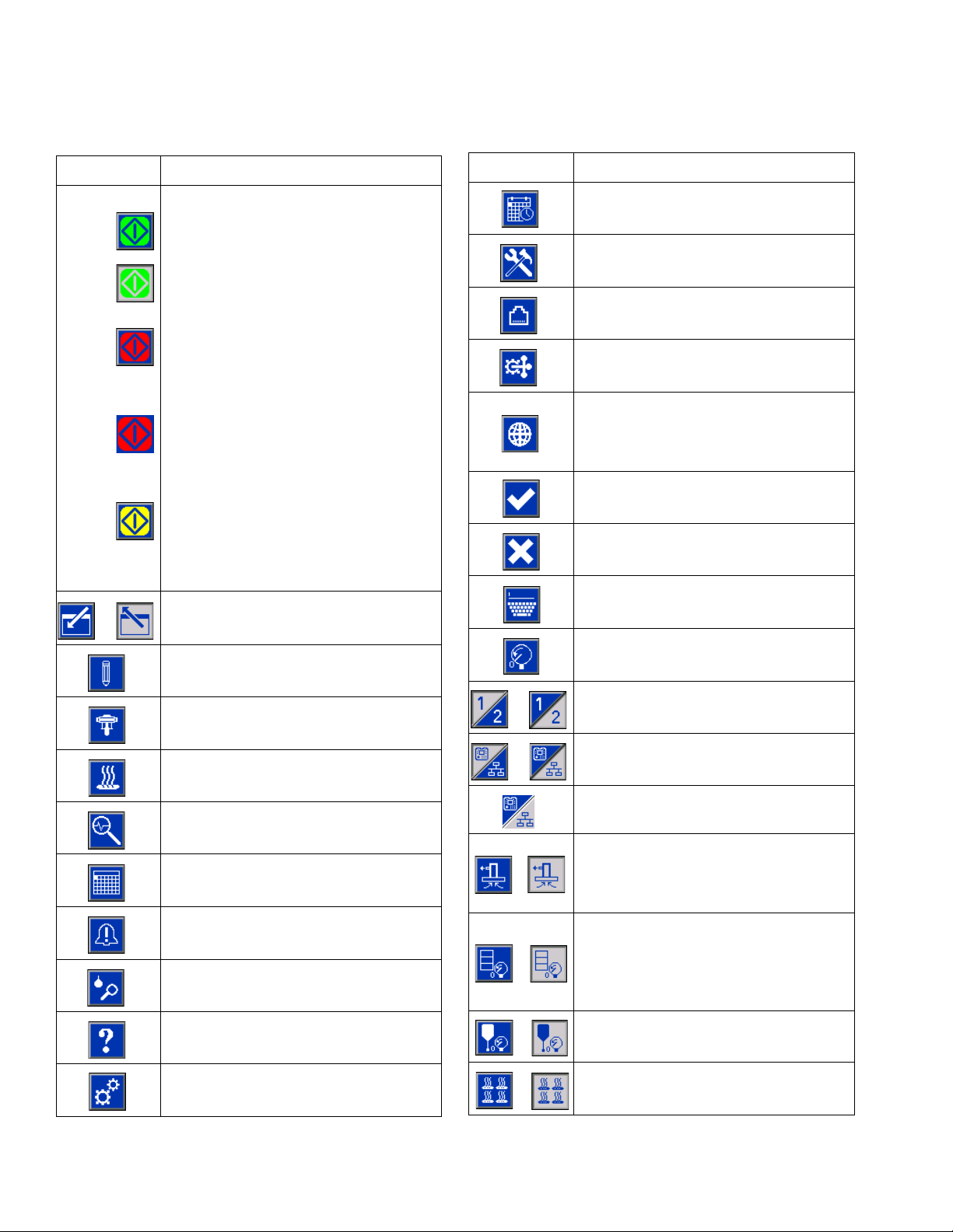
ADM Soft Keys
Icon Function
Pump Operation Icon
Green: Start the Pump
Inverted Green: Stop the Pump
Red with Border (enabled): Indicates
that the pump cannot be started due to
an alarm.
Red with No Border (not enabled):
Indicates that the system is not enabled
and the pump cannot be started.
Yellow: Indicates that the pump has an
active alarm but still allows the valve
and platen to be depressurized. The
pump can still be primed only if it is a
“pump not primed” alarm.
Enter or exit editing mode for a
particular screen.
Access the Style Definitions screens.
Icon Function
Access the Advanced System Setup
screens.
Access the Maintenance function.
Access the Fieldbus Gateway Setup
screens.
Access the Integration Feedback
screens.
Globalize selection. Apply a style setting
to all of the styles in Style Definitions or
a heat setting to all of the heat zones in
Heat Settings.
Confirm globalizing a setting.
Cancel globalizing a setting.
Access a keyboard screen to create or
change a style name.
Reset offsets to zero when calibrating
pressure transducers.
Access the Pump Setup screens.
Access the Heat Setup screens.
Access the Diagnostics function.
Access the Events logs.
Access the Errors logs.
Access the Job Log.
Access the Troubleshooting function.
Access the System Setup screen.
Tandem systems only. Toggle between
Pump 1 and Pump 2.
Local / Remote control toggle.
Pump is locked in remote control via
fieldbus interface.
Enter or exit pump priming mode. A “1”
or “2” will show on the icon in Tandem
systems to indicate which pump will be
primed.
Enter or exit drum depressurization
mode. (If equipped with optional fluid
solenoid.) A “1” or “2” will show on the
icon in Tandem systems to indicate
which pump will be depressurized.
Enter or exit valve depressurization
mode.
Turn heat zones on and off.
20 333587C
Page 21
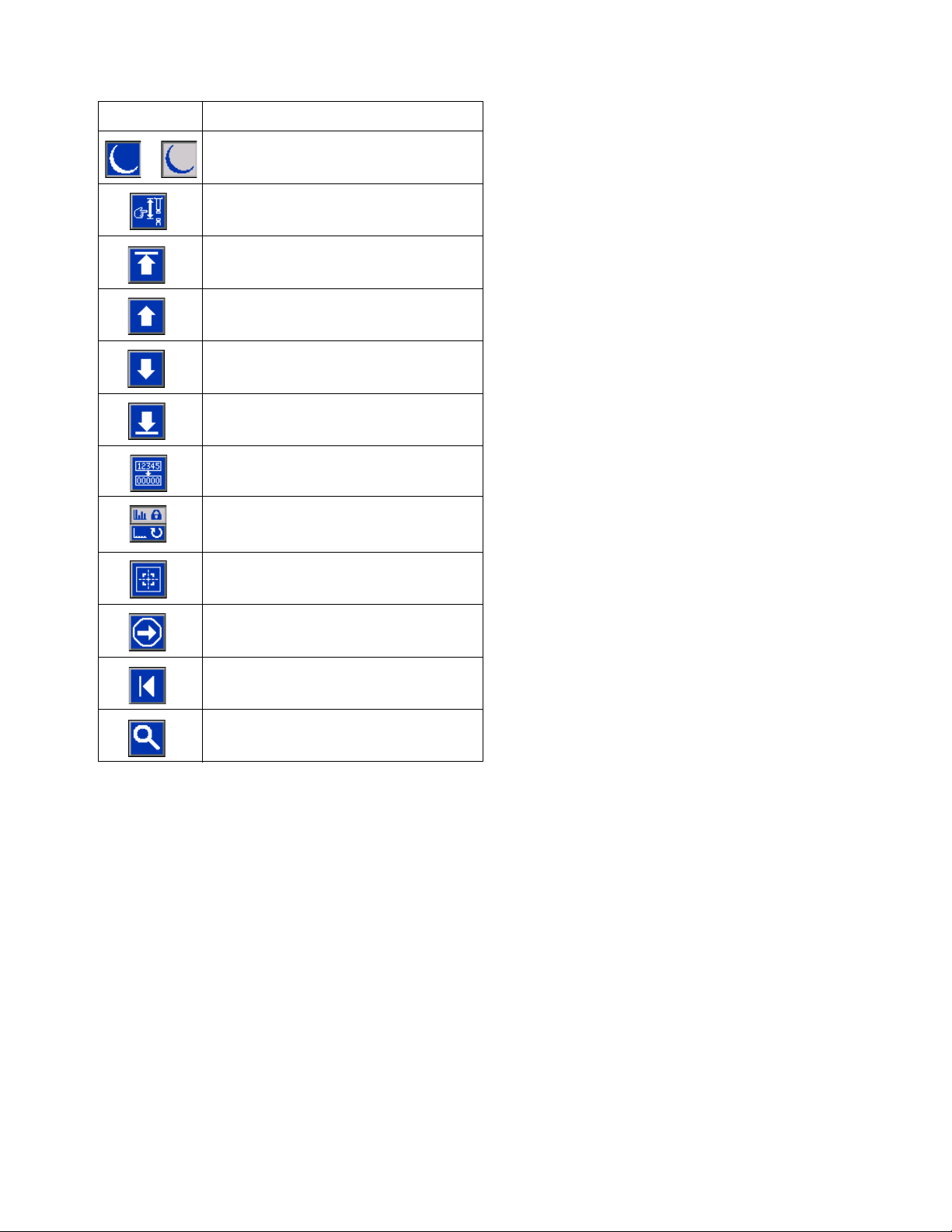
Icon Function
Place all heat zones into setback and
out of setback.
Enter or exit manual pump movement
mode.
Move to the top.
Move upward.
Move downward.
Move to the bottom.
Reset Cycle Counter.
Toggle between lifetime and resettable.
ADM Display Details
Calibrate.
Continue.
Previous screen.
Search.
333587C 21
Page 22
iQ Menu
iQ Menu
The iQ Menu screens provide access to settings that
help to ensure the proper operation and maintenance of
the system. These functions can be performed when the
ADM is either in Active or System OFF Mode.
1. Provide power to the system to turn on the ADM.
2. Press on the ADM from any Run screen to go
to the iQ Menu screens.
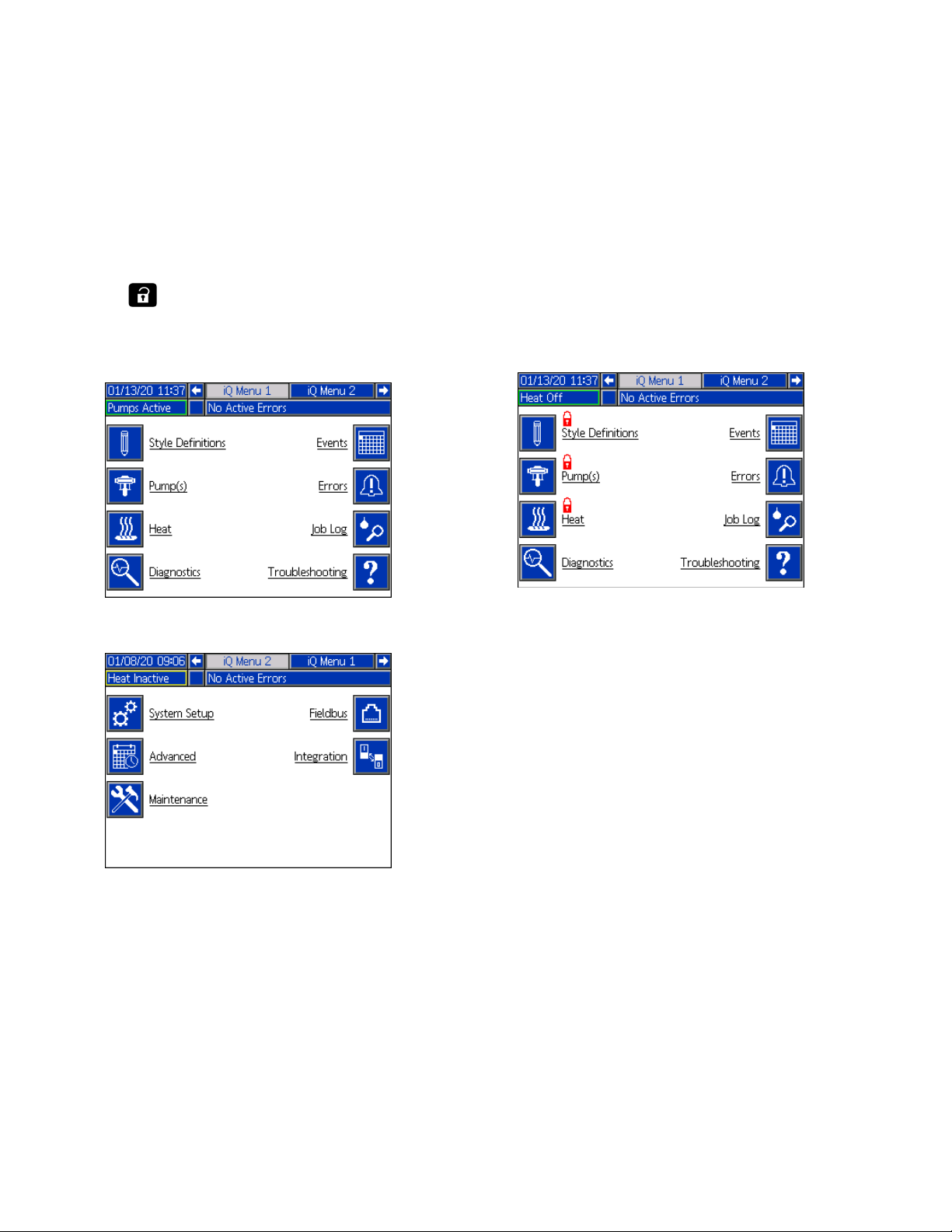
iQ Menu Screen 1
If you set a password, the menu will be displayed with
red locks above the menu selections with parameters
that can be changed. Enter your password when
prompted to access these screens.
The selections that do not have a red lock have
information that can be viewed but not changed and
would not require a password. See Advanced Setup
Screen 1 on page 31 for information about setting a
password.
iQ Menu Screen 2
22 333587C
Page 23
Setup
To prevent personal injury from pressurized fluid such
as skin injection or splashing fluid, make sure that all
components in your system are rated to the maximum
pressure the system is capable of attaining. All
components must be rated for maximum pressure
even if the pump is operated below maximum
pressure.
NOTICE
To prevent damage to ADM buttons, do not press the
buttons with sharp objects such as pens, plastic cards,
or fingernails.
NOTICE
To prevent damage to components in the system, all
components must be rated to the maximum pressure
the system is capable of attaining.
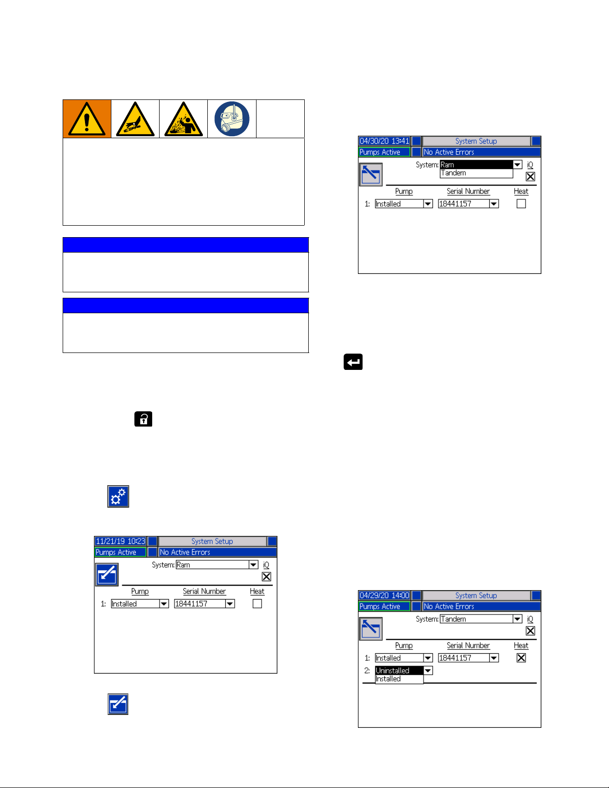
Setup
Use the drop down menu to select the type of system as
either Ram or Tandem.
NOTE: Changing the system type resets the pumps in
the system.
When you select Ram, the only action required at this
screen is if the pump has a heat module installed. Press
It is important to set up the parameters of your system
before operating the E-Flo iQ system. These are
accessed through the iQ Menu. After starting up the
ADM, press the key from the Run screen to go to
the iQ Menu screens. Refer to iQ Menu on page 22.
System Setup Screen
Press the soft key at the iQ Menu screen 2 to
access the System Setup screen.
the key in the Heat box to configure it for heat.
All other fields are automatically set when the blue token
is inserted on an installed system. The System is
displayed as Ram. The box below the iQ icon next to the
System field indicates that it is an E-Flo iQ system.
The Pump shows as Installed. The Serial Number
should match the serial number printed on the driver ID
tag. As a backup to the driver serial number, the serial
number of the current board will be displayed instead.
The serial number for the control board is also displayed
in the detailed software status screens. See Advanced
Setup Screen 4 on page 33.
When you select Tandem, a field for the second pump
is displayed on the screen showing Uninstalled. Select
Installed from the drop down menu.
Press the soft key to enter editing mode.
333587C 23
Page 24
Setup
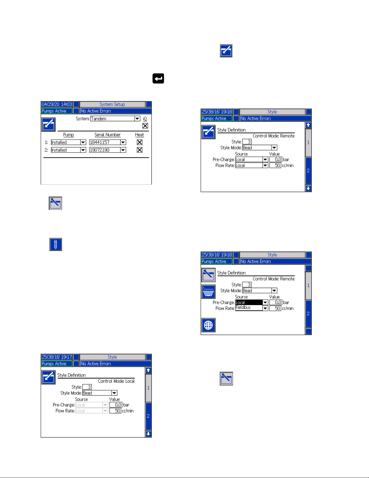
When you select installed, the Serial Number will be
automatically populated to match the serial number
printed on the driver ID tag on Pump 2.
If Pump 2 has a heat module installed, press the
key in the Heat box to enable it.
1. Press the soft key to enter editing mode.
2. Enter a Style identifier from 0-16. This is the
designation the system uses for the type of
dispensing based on how you define the style here.
3. Bead is automatically selected as the Style Mode.
Press the soft key to exit editing mode.
Style Definitions
Press the soft key at the iQ Menu screen 1 to
access the Style Definitions setup screens. This function
allows you to identify the style for dispensing material
and configure the settings of the style.
NOTE: Before accessing these settings, you need to
select if your system is running in Local or Remote
control mode. See Control Modes on page 40.
Style Screen 1 - Style Definition
NOTE: When in Local control mode, you cannot select
Source at this screen, but you can still enter Values. The
Source fields can be changed in Remote control mode.
4. From the Source drop-down menus, select the
Pre-Charge and Flow Rate as either Local or
Fieldbus. When you select Local, enter the
appropriate corresponding number in the Value
column. A Fieldbus selection does not require a
value.
NOTE: The optional Communications Gateway Module
(CGM) is required to use fieldbus.
5. Press the soft key to save your changes and
exit editing mode.
24 333587C
Page 25
Setup
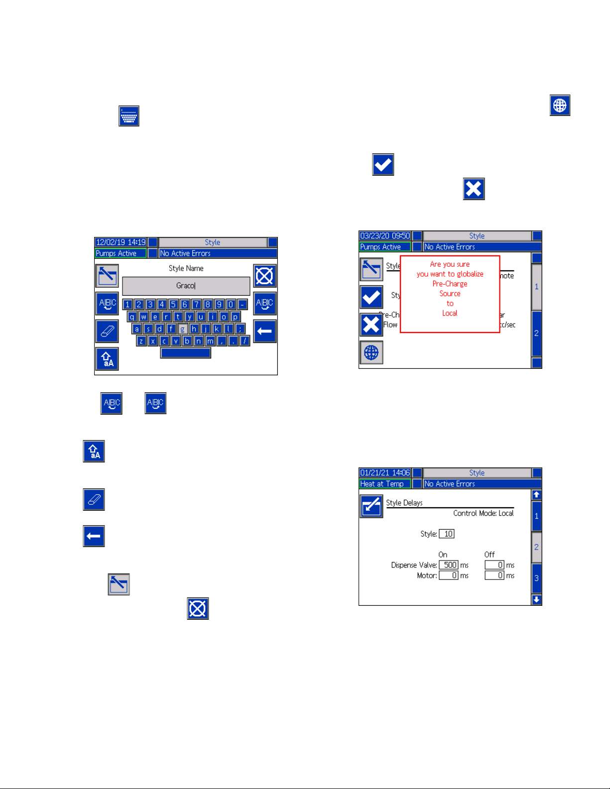
Name the Style
You can also name the Style. While still in Style screen
1, Press the soft key to advance to a keyboard
screen to create or change the name of the style based
on your needs.
NOTE: The Style identifier is a system requirement. The
Style Name option is not required. It is intended as a
user-defined description for the application of each
dispensing style. An example might be: Trunk Hem. The
maximum length is 11 characters.
Apply a Style Setting Globally
While still in Style screen 1, pressing the globalize
soft key applies a style setting across all of the styles. A
message will appear prior to completing the change.
Press the soft key to complete applying the
selected parameter. Press the soft key to cancel
the globalization.
Use the and soft keys to scroll the keyboard
to select letters.
The soft key changes back and forth from lower
and upper case.
The soft key erases everything you have typed.
The soft key is the backspace to delete one letter
at a time.
Press the soft key to save the name and exit the
keyboard screen. Press the soft key to exit the
screen without saving. Both actions return you to Style
screen 1.
Style Screen 2 - Delays
Use the ADM Directional Keypad (CH) to navigate to
Style screen 2.
Set the valve and motor On and Off delays.
333587C 25
Page 26

Setup
Style Screen 3 - Integration
Use the ADM Directional Keypad (CH) to navigate to
Style screen 3.
NOTE: You can only make changes to this screen in
Remote mode. In Local mode, the screen appears as
shown below.
1. In Remote mode, press the soft key to enter
editing mode.
Pump Settings
Press the soft key at iQ Menu screen 1 to access
the Pump setup screens. This function allows you to
configure the operating settings for the pump and drum
depending on the mode of operation.
Pump Screen 1 - Pump Settings
The following description is the same for both Ram and
Tandem selections. For Tandem, Pump 1 and Pump 2
are shown in the Menu Bar. Use the ADM Directional
Keypad to select each pump for configuration. The
Tandem screen is shown below.
2. Set Style Enable and Go Signal fields to either
Discrete or Fieldbus depending on your
requirements. It is recommended that you select
Discrete for the Go Signal to avoid start and stop
delays.
3. Set Dispense Complete to Discrete, Fieldbus, or
Timer. If you select Timer, enter the number of
seconds for the timer from 0-999.
4. Press the soft key to save your changes and
exit editing mode.
26 333587C
NOTE: in Tandem systems, it is recommended that both
pumps should be configured with identical pimp
settings.
Follow these steps to configure the operating settings for
each pump in a Tandem system or a single pump in a
Ram system.
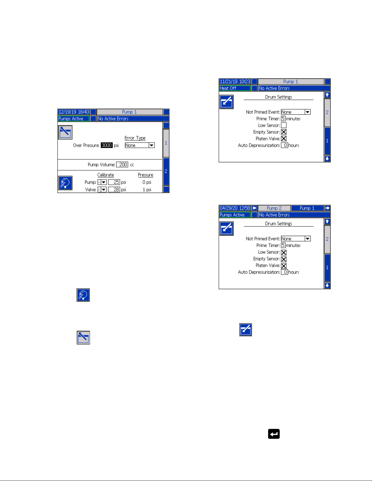
1. Press the soft key to enter editing mode.
2. Configure the Over Pressure setting by entering a
pressure limit.
Page 27
Setup
3. Select Alarm, Deviation, or None from the drop
down menu for the Error Type.
NOTE: The Over Pressure error will be triggered if the
limit is exceeded for 1 second. An Alarm sends an error
message and deactivates the system. A Deviation
sends an error message but the system continues to
operate.
4. The Pump Volume shows the pump size in cc and
can be changed in editing mode if needed.
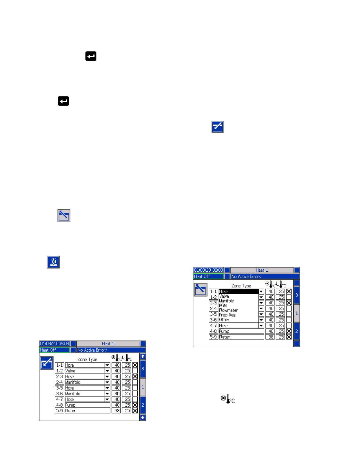
Pump Screen 2 - Drum Settings
Use the ADM Directional Keypad (CH) to navigate to
Pump screen 2.
As with the first pump screen, Pump Screen 2 shows
both pumps in the Menu Bar in a Tandem system as
shown below.
NOTE: Pressure transducers are calibrated at the
factory, but calibration may be necessary after extended
use. The pump transducer offset and the valve
transducer offset are shown in the Calibrate section.
5. Relieve pressure in the system using Valve
depressurization. See Depressurization Mode on
page 40.
6. Press the soft key to automatically reset the
offsets to zero. You can also manually change the
values and select minus or plus from the drop down
menus as appropriate for the calibration.
7. Press the soft key to save your changes and
exit editing mode.
The steps for configuring the settings are the same for
both Ram and Tandem.
1. Select the soft key to enter editing mode.
2. Select the error type from Alarm, Deviation, and
None for the Not Primed Event. This is triggered
when a drum is replaced and the pump has not yet
been primed. If Alarm is selected, the pump must be
primed after replacing a drum and before returning
to normal operation.
3. Enter the length of the pump Prime Timer between
1 and 9 minutes. Five minutes is the default value.
See Priming Mode on page 41.
4. By default, the Low Sensor box is unchecked
(disabled). Press the key to enable the drum
low deviation.
333587C 27
Page 28
Setup
5. By default, the Empty Sensor box is checked
(enabled). Press the key to disable the drum
empty alarm if needed.
NOTE: The Low Sensor and Empty Sensor errors are
triggered 3 seconds after reaching a critical level.
6. Press the key to enable the Platen Valve
setting. This must be enabled to be able to change
flow rates between dispenses and to allow platen
depressurization. This setting only applies to an
E-Flo iQ system that has a Platen Valve installed.
7. Auto Depressurization allows the platen valve to
open and depressurize the system back to the
platen based on this setting. Enter a value between
1 and 24 hours.
NOTE: The Platen Valve must be enabled on the screen
to trigger Auto Depressurization. If heat is installed, it
places the system into setback. A zero value in the field
disables this feature.
8. Press the soft key to save your changes and
exit editing mode.
Heat Settings
NOTE: For Tandem systems, read this section first, then
refer to Tandem Heat Setup Screen 1 on page 29.
The heat zone number in the first column corresponds
to the connector and heat zone on the Automatic
Multi-Zone (AMZ) heat control. For example, heat zone
number 4-7 corresponds to connector 4 and heat zone
7. For information about the AMZ, refer to the E-Flo iQ
Supply Systems, Installation-Parts manual. See
Related Manuals on page 3.
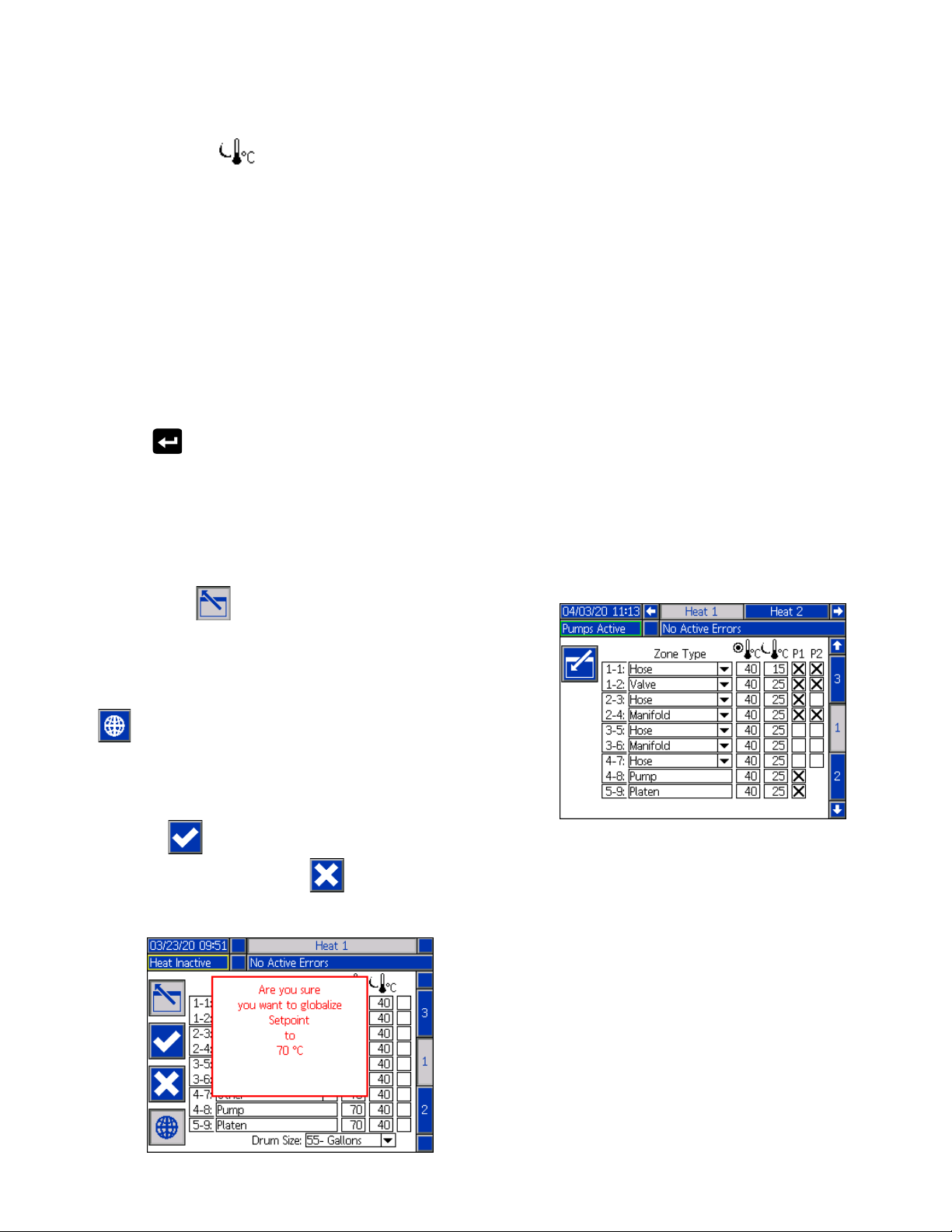
1. Press the soft key to enter editing mode.
2. The Zone Type column refers to the system
component that the zone is heating. Select a zone
type from the drop down menu for each zone. The
options available in the drop down menu are:
•Hose
•Valve
• Manifold
• PGM (Precision Gear Motor)
• Flowmeter
• Press Reg (Pressure Regulator)
•Other
NOTE: The correct zone type has to be selected for the
zone to properly heat. If an incorrect zone type is
selected, errors, overshoots, and long heat up times can
occur.
Press the soft key at the iQ Menu screen 1 to
access the Heat setup screens. These screens allow
you to configure the operating settings for the Heat
function.
NOTE: Heat must be selected at the System Setup
screen for these selections to be available. See the
System Setup Screen on page 23.
Heat Setup Screen 1
NOTE: There are two other zone types: platen and
pump. The zones for these are always 4-8 and 5-9,
respectively, as shown above.
3. Enter a temperature for the zone setpoint
temperature ( ) column. This is the setpoint
that the zone heats to when the heat is turned on.
The temperature units can be changed from °C to
°F in the Advanced settings screens. See
Advanced Setup Screen 2 on page 32.
28 333587C
Page 29
Setup
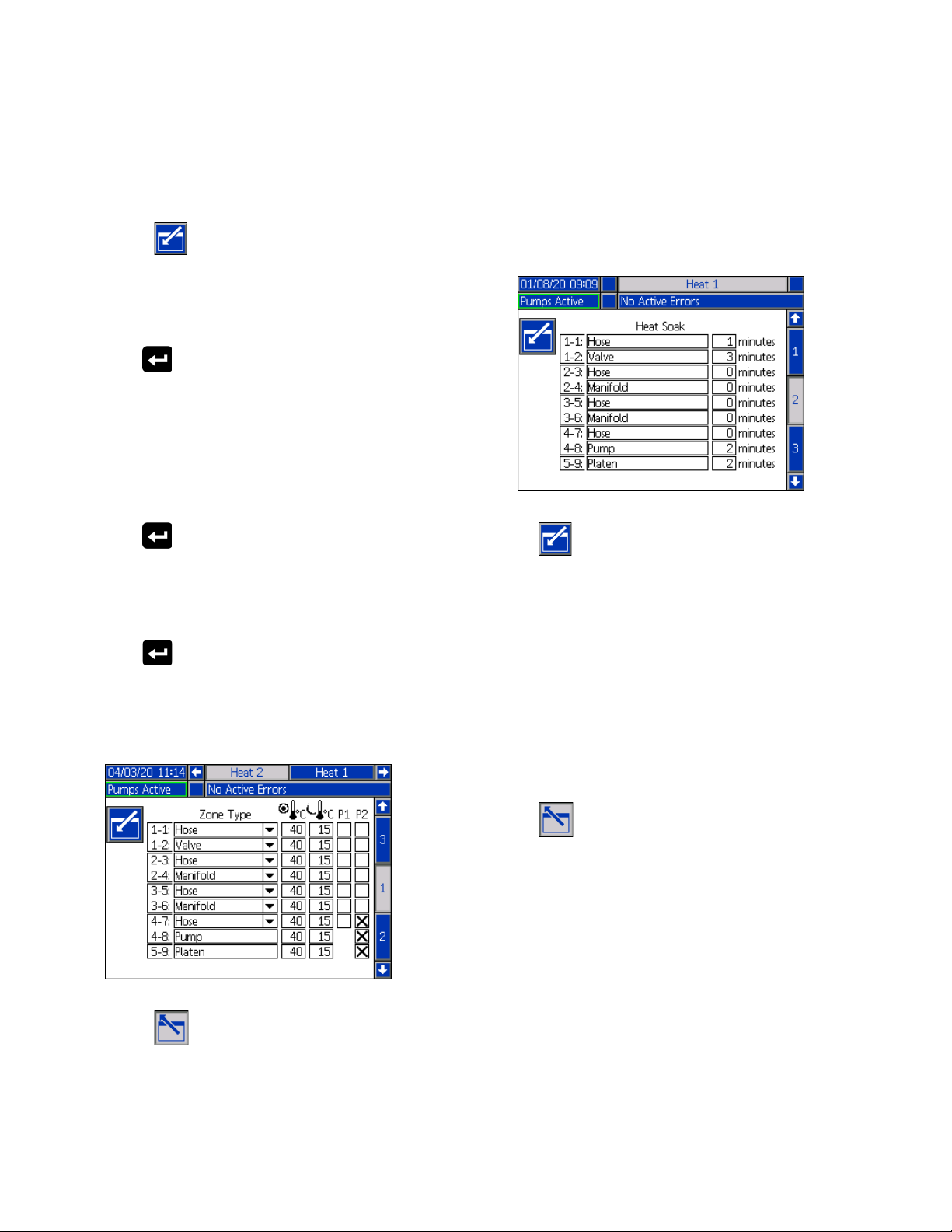
4. Enter a temperature for the zone setback
temperature ( ) column. This is the setback that
the zone goes to when the heat is in setback. The
temperature units can be changed from °C to °F in
the Advanced settings screens. See Advanced
Setup Screen 2 on page 32.
NOTE: If you change a setpoint temperature to a value
below the current setback temperature, that value
becomes the new setback temperature. If you increase
a setback temperature to a value above the current
setpoint temperature, that value becomes the new
setpoint temperature.
5. The column on the right side of the zone setback
temperature column is for enabling the zone. Use
the key to enable zones.
NOTE: When enabled, the zone will be displayed on the
Heat Run screen. When the box is disabled, the zone
will not be displayed on the Heat Run screen and the
errors for that zone will be ignored. See Heat Run
Screen on page 42.
Tandem Heat Setup Screen 1
Read all of Heat Setup Screen 1 starting on page 28
before reading this section.
The Heat Setup screens for Ram and Tandem are the
same in appearance except Tandem has an additional
column to the right for the second pump.
One of the advantages of a Tandem system is
continuous operation if a pump needs to be shut down
for any reason, such as changing a drum of material. In
a heated system, it is equally important to maintain heat
for the entire system when one of the pumps is shut
down.
NOTE: Heated systems have a red and black Power
Junction Box Switch (AK) that removes power to
everything EXCEPT heat on the ram supply unit. This
allows a ram supply unit to continue to heat the system
with the power to the ram turned off. See Power
Disconnect on page 14 for more information.
The Tandem Heat setup screen 1 allows you configure
how you want heat to be controlled for the entire system.
6. Press the soft key to save your changes and
exit editing mode.
Apply a Heat Setting Globally
While still in Heat Setup screen 1, press the globalize
soft key to apply a setpoint or setback heat setting
across all of the heat zones.
A message will appear prior to completing the change.
Press the soft key to complete applying the
selected parameter. Press the soft key to cancel
the globalization.
Heat 1 in the Menu Bar is for the Heat Control Box (AX)
on the Pump 1 ram and Heat 2 is for the Heat Control
Box (AX) on the Pump 2 ram. The heat control box on
each ram controls heat to its pump, platen, and the hose
that runs from the pump to the Ball Valve (S) on the
Tandem Block (R).
Since all components from the Tandem Block R) to the
Dispense Valve (B) are shared by both pumps and need
to be heated continuously while the system is in
operation, you can designate one pump to control the
shared components at this screen.
NOTE: The cables for heat from the shared components
must be connected to the Heat Control Box (AX) on the
designated pump.
333587C 29
Page 30
Setup
In this example, the heat control box on Pump 1 (P1) is
the one selected to heat the shared components
running from the Tandem Block (R) to the Dispense
Valve (B).
1. Press the soft key to enter editing mode.
2. Configure your Zone Type and setpoint and setback
temperatures as described in Heat Setup Screen 1
on page 28.
3. Use the key to enable the zones under P1 that
will control the heat for the entire system.
NOTE: Since P1 will be the heat control for the shared
components, you need to enable the same zones for P2
while at the Heat 1 screen. This sets P1 to control the
heat for its pump, platen, and hose while also controlling
the heat for the components that P1 and P2 share.
4. Use the key to enable the zones under P2 that
are enabled under P1.
5. Use the ADM Directional Keypad (CH) to move to
Heat 2 in the Menu Bar.
6. Use the key to enable only the pump and
platen zones and the zone for the hose that runs
from the ram supply unit for P2 to the Ball Valve (S)
on the Tandem Block (R) since all others are
controlled by P1.
Heat Setup Screen 2 - Heat Soak
Use the ADM Directional Keypad (CH) to navigate to
Heat screen 2. This screen is the same for Ram and
Tandem except for the additional Heat 2 selection in the
Menu Bar. Make sure you configure heat soak time for
both Heat 1 and Heat 2 in a Tandem system.
Press the soft key to enter editing mode.
The heat soak time in the far right column is the amount
of additional time that the heat zone needs to ensure
that the material is heated evenly throughout after the
zone is up to temperature. Enter a time in minutes.
NOTE: Three minutes is the minimum amount of heat
soak time needed to make sure that the dispense valve
is completely up to temperature.
The Zone Types can only be changed at the Heat Setup
screen 1. See Heat Setup Screen 1 on page 28.
Press the soft key to save your changes and exit
this screen.
7. Press the soft key to save your changes and
exit editing mode.
30 333587C
Page 31

Setup
Heat Setup Screen 3
Use the ADM Directional Keypad (CH) to navigate to
Heat screen 3. The Tandem screen is shown below. The
Ram screen is identical except for only having Heat 1 in
the Menu Bar. Make sure you configure these settings
for both Heat 1 and Heat 2 in a Tandem system.
1. Press the soft key to enter editing mode.
2. In the Temp Offset Errors section, set the variance
in degrees allowed from a zone temperature setting
before a deviation and alarm is triggered. The
default values are 15 for deviations and 25 for
alarms. You can enter other temperature values.
For example, if the zone temperature is set at 50
degrees and you set +15 degrees for a High
Deviation and +25 degrees for a High Alarm, the
deviation will occur when the temperature reaches
65 (50 +15) and the alarm will occur when it reaches
75 (50 + 25).
heated. To avoid overshooting material heat, select
the appropriate option based on the running
temperature.
NOTE: If material heat overshoots on a particular heat
rate setting, select a slower heat rate.
Running Temperature Heat Rate Option
26° C - 40° C Slow
41° C - 55° C Normal
56° C - 70° C Fast
5. The Drum Size at the bottom of the screen shows
the size of the drum for that ram supply unit. Select
the correct drum size from the two options: 5 Gallon
Drum and 55 Gallon Drum. The correct drum size
must be selected to properly heat the platen.
6. Press the soft key to save your changes and
exit this screen.
Advanced Setup
Use the ADM directional keypad (BH) to change to iQ
Menu screen 2. Press the soft key to access the
Advanced Setup screens. This function allows you to
configure the operating settings for E-Flo iQ system.
Advanced Setup Screen 1
1. Press the soft key to enter editing mode.
The same applies to the Low Alarm and Low
Deviation settings. In the same example at 50
degrees with a Low Deviation of -15 and a Low
Alarm of -25, the deviation will occur when the
temperature reaches 35 (50-15) and the alarm will
occur when it reaches 25 (50-25).
NOTE: These offsets apply to all of the heat zones in
the Ram or Tandem system.
3. The Heat Idle Timeout feature provides the
capability to deactivate heat after the pump has not
moved for a selected number of hours. Enter the
number of hours in the box provided.
4. Select a Heat Rate Option from the drop down
menu. The available options are slow, normal, and
fast. The heat rate controls how fast the material is
333587C 31
2. Select the Language from the drop down menu.
Available languages are English, Spanish, French,
German, traditional Chinese, Japanese, Korean,
Portuguese, Italian, and Russian.
Page 32

Setup
3. Select a Date Format from the drop down menu.
The available formats are mm/dd/yy, dd/mm/yy,
yy/mm/dd.
4. Enter numeric values for the month, day, and
two-digit year in the Date field.
5. Enter numeric values in the Time field for the
24-hour clock in hours and minutes.
6. Enter the number of minutes of inactivity before the
Screen Saver turns off the screen back-lighting.
Enter a 0 to leave it on constantly. Press any key to
disable the screen saver.
7. For the Password, enter any numbers from 0001 to
9999. To remove the password, change the
password to 0000. This disables the password
function.
NOTE: When you use a password, some iQ Menu
selections will require the password for access. See iQ
Menu on page 22 for additional information.
8. For the Password Timeout, enter a time in minutes
that allows you to temporarily move throughout the
screens without having to enter a password. The
timeout starts after returning to the Run screen.
Once the time has expired, you must enter the
password again.
9. Enabling the Display Control Password feature
requires you to enter the password before switching
from Remote to Local control mode. See Control
Modes on page 40. This protects against
inadvertently changing out of Remote control mode.
If the password is disabled by being set to 0000, this
feature will not function even if it is set to Enable.
Press the soft key to save your changes and exit
editing mode.
1. Press the soft key to enter editing mode.
2. Select between psi, bar, and MPa for the Pressure
Units.
3. Select the Rate between x/min and x/sec.
4. Select the Flow Rate from cc, gal(US), gal(UK),
oz(US), oz(UK), liters, or cycles.
5. Select the Drum Volume from cc, gal(US), gal(UK),
oz(US), oz(UK), liters, or cycles.
6. Select the Temperature between °C and °F.
7. For Enabled Temp Adjustments, use the key to
select to Enable or Disable temperature
adjustments. Enabling this feature allows you to
change temperature setpoints and setbacks through
the Heat Run screen. See Heat Run Screen on
page 42.
8. Press the soft key to save your changes and
exit editing mode.
Advanced Setup Screen 3
Advanced Setup Screen 2
Use the ADM directional keypad (BH) to navigate to
Advanced Screen 2. This screen allows you to select
units of measurement, rates, and the type of
temperature scale to use for the operation of your
system.
32 333587C
Use the ADM Directional Keypad (CH) to navigate to
Advanced Screen 3. The parameters on this screen
pertain to USB downloads.
Page 33

Setup
1. Press the soft key to enter editing mode.
2. USB downloads automatically begin when a USB
drive is inserted. Use the key to disable this
feature in the Disable USB Downloads/Uploads box.
3. If you do not want USB log errors to be generated
on the ADM, use the key to disable this feature
in the Disable USB Log Errors box.
4. For the Download Depth: Last feature, set the
desired download depth using the keypad and
key to enter the desired number of days. This
specifies how many days worth of pump data will be
kept in the USB logs. Once the logs fill up, the
oldest recording will be overwritten.
5. To enable a time frame range of data to download
upon insertion of a USB drive, use the key in
the Data Range Prompt Enable box.
6. Press the soft key to save your changes and
exit editing mode.
Advanced Setup Screen 4
Use the ADM Directional Keypad (CH) to navigate to
Advanced Screen 3.
This screen can be used to view the version of software
used in the system. Additionally, this screen is used to
update the system software using a USB drive with the
latest software and a Graco black token. The latest
software is provided on Help.graco.com.
Refer to the ADM Token In-System Programming
manual for a detailed description of this screen. See
Related Manuals on page 3.
Connect Light Tower Assembly
1. Order the 255468 Light Tower Accessory as a
diagnostic indicator for the E-Flo iQ System.
2. Connect the cable from the light tower to the digital
I/O port (CS) on the ADM (AF).
Signal Description
Off System is not active
Green Only On System is active and no errors are
present
Blinking Green Heat is warming up
Yellow On An advisory exists
Blinking Yellow A deviation exists
Red solid The system is shut down due to
an alarm occuring
NOTE: See Troubleshooting on page 53 for error
definitions.
333587C 33
Page 34

Startup
AE
Connect
Hose
Startup
Letters in parenthesis are used in this section for reference to callouts in the Component Identification sec-
tion starting on page 11.
Flush the Pump
To avoid fire and explosion, always ground the equipment and the waste container. To avoid static spark-
ing and injury from splashing, always flush at the
lowest possible pressure.
NOTE: Pumps (AC) are tested with lightweight oil,
which is left in to protect the Pump parts. If the material
you are using may be contaminated by the oil, flush it
out with a compatible solvent before using the Pump
(AC).
3. Connect a hose to the 1 in. npt fitting on the top of
the Check Valve Block (AE). Place the other end of
the hose into a grounded waste container.
4. Turn on the Disconnect Switch (AZ). If using a
heated system, also turn on the Power Junction Box
switch (AK).
5. Press the Startup button (CA) on the ADM (AF) to
enable the system.
6. At the ADM (AF) Run screen, press the soft key
next to the icon to enter editing mode.
Always flush at the lowest pressure possible. Check
connectors for leaks and tighten as necessary. Flush
with a fluid that is compatible with the material being dis-
pensed and the equipment wetted parts.
NOTE: Check with your material manufacturer or supplier for recommended flushing fluids and flushing fre-
quency.
NOTICE
To prevent damage to the pump from rust, never
leave water or water-based fluid in a carbon steel
pump overnight. If you are pumping a water-based
fluid, flush with water first. Then flush with a rust
inhibitor, such as mineral spirits. Relieve pressure,
but leave the rust inhibitor in the pump to protect
parts from corrosion.
For information about Priming the system, refer to
Priming Mode on page 41.
1. Follow the Pressure Relief Procedure on page 46.
2. Place a pail of compatible solvent in the Ram (AA).
7. Press the soft key to enter the pump priming
mode. Two fields appear on the screen next to the
pump: target pressure (top) and target flow (bot-
tom).
8. Enter 100 psi (0.7 MPa, 7 bar) as the target pres-
sure and enter 25 cc/min as the target flow.
9. Press the soft key to initiate the Pump (AC)
and start flushing the system. This loads the solvent
into the Pump (AC).
10. Adjust pressure as necessary and flush the system
until clear solvent flows from the hose.
11. Press the soft key to stop the Pump (AC).
12. Press the soft key to exit editing mode.
13. Follow the Pressure Relief Procedure on page 46.
14. Remove the solvent pail from the Ram (AA).
15. Repeat steps 1 through 14 for the second pump in a
Tandem system.
34 333587C
Page 35

Load Material
Platen Valve
Port with Cap
Recirculation
Hose (ZB)
Platen Wiper
Platen Bleed
Stick
The following steps are required when you are loading
material in the system for the first time. This procedure
should be performed after the E-Flo iQ system is
installed, flushed, and ready for operation. Refer to the
E-Flo iQ Supply System Installation-Parts manual for
installation. See Related Manuals on page 3.
Startup
7. Place a full pail or drum of material on the Ram (AA)
base and center it under the Platen (AD). Then
remove the drum cover and smooth the surface of
the material with a straightedge.
8. To prevent air from being trapped under the Platen
(AD), scoop fluid from the center of the pail/drum to
the sides to make the surface concave.
9. Adjust the pail/drum to make sure it is aligned with
the Platen (AD).
10. Remove the Platen Bleed Stick to open the Platen
Bleed Port (AH).
For additional information about the E-Flo iQ Run
screens, including priming and depressurization, see
Operation on page 38.
NOTE: For an E-Flo iQ system with a Platen Valve (AY)
installed, you need to ensure that the Platen Valve
setting is enabled in the Pump Settings on the ADM
before starting this procedure. See Pump Screen 2 -
Drum Settings on page 27.
NOTE: For Tandem systems, complete all steps in the
following sections on both ram supply units before
performing the steps in Load the Hose and Dispense
Valve:
• Prepare the Pump
• Load the Platen and Platen Valve
• Load the Pump
• Load the Platen Valve and Recirculation Hose
Prepare the Pump
1. For Tandem Systems, ensure the Ball Valves (S) on
the Tandem Block (R) are closed.
2. Turn on the Disconnect Switch (AZ). If using a
heated system, also turn on the Power Junction Box
switch (AK).
NOTE: If a Platen Valve (AY) is installed on the system,
do not connect the Recirculation Hose (ZB) to the Platen
Valve Port until you have completed loading material
through the system.
11. With your hands away from the pail/drum and the
Platen (AD), move the Ram Director Valve (BC)
down to lower the Ram (AA) until the Platen (AD)
rests on the lip of the pail/drum.
12. Return the Ram Director Valve (BC) to the neutral
position.
Load the Platen and Platen Valve
3. Open the Main Air Slider Valve (BA) on the
Integrated Air Control and set the Ram Air
Regulator (BB) to 40 psi (.20 MPa, 2.0 bar).
4. Move the Ram Director Valve (BC) up to raise the
Ram (AA) to its full height.
5. Set the Ram Director Valve (BC) to neutral
(horizontal position).
6. Lubricate the Platen Wiper with grease or another
lubricant compatible with the material being loaded.
333587C 35
1. For Tandem systems, ensure the Ball Valves (S) on
the Tandem Block (R) are closed.
2. Move the Ram Director Valve (BC) down to lower
the ram until material appears at the Platen Bleed
Port (AH).
3. Return the Ram Director Valve (BC) to the neutral
position.
4. Replace the Platen Bleed Stick that was removed in
step 8 in Prepare the Pump.
Page 36

Startup
5. If a Platen Valve (AY) is installed on the system,
remove the cap from the Platen Valve Port located
on the platen.
6. Move the Ram Director Valve (BC) down to lower
the ram again until material appears the Platen
Valve Port.
7. Return the Ram Director Valve (BC) to the neutral
position.
8. Replace the Platen Valve Port cap.
Load the Pump
1. For Tandem systems, ensure the Ball Valves (S) on
the Tandem Block (R) are closed.
2. Move the Ram Director Valve (BC) down to lower
the Ram (AA).
3. At the ADM (AF), press the soft key to enter
the pump priming mode. Two fields appear on the
screen next to the pump: target pressure (top) and
target flow (bottom).
4. Enter 100 psi (0.7 MPa, 7 bar) as the target
pressure and enter 25 cc/min as the target flow.
NOTE: Loading the material at the low pressure and
flow rate in step 3 keeps the Pump (AC) from cavitating,
since there is no material loaded in the Pump (AC).
NOTE: Priming mode has a timer that is shown to the
left of the priming mode icon and counts down when the
priming starts. The default is 5 minutes. If time expires
before you are done loading material to the system,
press the soft key to restart priming mode. Your
target pressure and flow settings remain the same.
Load the Platen Valve and Recirculation
Hose
NOTE: The following steps only apply to systems that
include the Platen Valve (AY). For systems without a
Platen Valve, go to step 1 in Load the Hose and Valve.
1. For Tandem systems, ensure the Ball Valves (S) on
the Tandem Block (R) are closed.
2. Place the Recirculation Hose (ZB) into a waste
container.
3. While still in pump priming mode and with the target
pressure still set at 100 psi (0.7 MPa, 7 bar) and the
target flow at 25 cc/min, press the soft key to
enter the platen depressurization mode.
4. Press the soft key to start the Pump (AC).
5. Increase pressure and flow rates on the screen as
necessary.
6. Run the Pump (AC) until a steady stream with no air
flows out of the Recirculation Hose.
7. Press the soft key to stop the Pump (AC).
8. Press the soft key to exit the platen
depressurization mode.
9. Move the Ram Director Valve (BC) to the neutral
position.
10. Remove the cap from the Platen Valve Port.
11. Install the Recirculation Hose (ZB) to the Platen
Valve Port and tighten until secure.
5. Open the Pump Bleed Valve (AM) and place a
waste container below it to catch material.
6. Press the soft key to start the Pump (AC).
7. Increase pressure and flow rates on the screen as
necessary to fill the Pump (AC) with material.
8. When a steady stream of material with no air comes
out of the Pump Bleed Valve (AM), close the valve.
9. Press the soft key to stop the Pump (AC).
36 333587C
NOTE: It is important to load the Platen Valve (AY) and
Recirculation Hose (ZB) with material before connecting
it to the Platen Valve Port to ensure no air is introduced
into the material. Failure to follow these steps could
cause air pockets in the material.
Load the Hose and Dispense Valve
NOTE: For Tandem systems, ensure that the previous
four sections are completed for both ram supply units
before performing these steps.
1. On a Tandem system, open the Ball Valves (S) on
the Tandem Block (R).
Page 37

2. Place a waste container below the Dispense Valve
(A).
3. Ensure all fittings are secure from the Pump (AC)
out to the Dispense Valve (A).
4. While still in pump priming mode and with the target
pressure still set at 100 psi (0.7 MPa, 7 bar) and the
target flow at 25 cc/min, press, the soft key to
enter the valve depressurization mode on Pump 1.
5. Press the soft key to start the Pump (AC). This
will open the Dispense Valve (A) and allow the
pump to run at the set pressure and flow rate.
6. Increase pressure and flow targets as necessary
until a steady stream with no air flows out of the
Dispense Valve (A).
7. Press the soft key to stop the Pump (AC).
Startup
5. Press the soft key to enter the pump priming
mode.
6. To control the flow of material, set your target
pressure and target flow in the fields that are
displayed above the line and style number. Ensure
that the target prime pressure is at least 100 psi
below current system operating pressure, but not
less than 400 psi below current operating pressure.
8. Press the soft key to exit the valve
depressurization mode.
9. Press the soft key to exit priming mode
Tandem Priming when Changing Drums
When priming one ram supply unit of a Tandem system,
the other ram does not need to be stopped when you
want to change material drums. The other pump can
continue running and dispensing material.
NOTE: This can only be performed when the system is
in Remote control mode. For priming pumps in Local
mode during operation, see Priming Mode on page 41.
1. Press the soft key to change to Remote
control mode. If PLC lockout is active, the inactive
pump must be primed through the CGM.
2. Adjust the drum to make sure it is aligned with the
Platen (AD). See Prepare the Pump on page 35.
3. Open both Ball Valves (S) on the Tandem Block (R).
7. Open the Pump Relief Valve (ZC) on the ram and
place a waste container below it to catch material.
8. Press the soft key to start the priming process.
9. Allow adequate amount of time for air to escape the
system through the Pump Relief Valve (ZC) while
priming. At least 30 seconds with no air pockets is
recommended.
NOTE: A timer shows to the left of the priming mode
icon and counts down during priming. The default is 5
minutes but can be adjusted between 1 and 9 minutes.
See Pump Screen 2 - Pump Settings on page 27.
10. When a steady stream of material with no air comes
out of the Pump Relief Valve (ZC), close the Pump
Relief Valve.
11. To manually stop the priming process at any time,
press the soft key. If you do not manually stop
the process, it will automatically stop when the timer
counts down to 0:00.
NOTE: If time has expired, you must press the soft
key again to resume priming. Do not press the soft
4. Press the soft key to switch to the currently
operating ram supply unit. The one currently
operating is highlighted in green. The Prime icon
displays the number of the other ram for priming.
333587C 37
key until you have restarted the priming process.
12. Press the soft key to exit the priming mode.
Page 38

Operation
1
7
6
5
4
3
2
8
11
10
9
16
15
14
13
12
17
Operation
Ram Run Screen
1. Toggles between two modes of control: Local and
Remote. See Control Modes on page 40.
2. Select to enter or exit the editing mode for the
screen.
3. Indicates whether or not an error is active on this
pump and the pump status. See Pump Status on
page 40.
4. Displays the current pump pressure.
5. Displays the current dispense valve pressure.
6. Shows the status of the dispense valve. Green is
on, gray is off.
7. Used to run beads manually. This is only available
when the system is in Local mode. See Manual
Pump Operation on page 40.
8. Select to enter or exit drum depressurization mode.
9. Select to enter or exit dispense valve
See Depressurization Mode on page 40.
depressurization mode. See Depressurization
10. Select to enter or exit priming mode. See Priming
Mode on page 41.
11. Displays the Actual amount of material.
12. Displays the current flow rate.
13. Displays the name of the style that you have
assigned. See Style Screen 1 - Style Definition on
page 24.
14. Shows the Style identification number that is
currently in use. See Style Screen 1 - Style
Definition on page 24.
15. Displays the size of the pump.
16. Shows the status of the Platen valve used during
pump depressurization. Green is on, gray is off.
17. Displays the current mode of control (Local or
Remote). See item 1.
NOTE: The pump and material line show animated
operation and material flow when dispensing.
Mode on page 40.
38 333587C
Page 39

Tandem Run Screen
1
7
6
18
4
3
2
8
11
10
9
16
15
14 13
12
17
5
19
Operation
1. Toggles between two modes of control: Local and
Remote. See Control Modes on page 40.
2. Select to enter or exit the editing mode for the
screen.
3. Displays the current pump pressure.
4. Shows the pump currently selected as green.
5. Shows the status of the Platen valve used during
pump depressurization. Green is on, gray is off.
6. Low material level and empty material level
indicators. Shows as red when low or empty. See
Low Level and Empty Level Indicators on page
41.
7. Displays the current dispense valve pressure.
8. Used to run beads manually. This is only available
when the system is in Local mode. See Manual
Pump Operation on page 40.
9. Select to enter or exit drum depressurization mode.
See Depressurization Mode on page 40.
10. Select to enter or exit dispense valve
depressurization mode. See Depressurization
Mode on page 40.
11. Select to enter or exit priming mode. See Priming
Mode on page 41.
12. Shows the status of the dispense valve. Green is
on, gray is off.
13. Displays the current flow rate.
14. Displays the Actual amount of material.
15. Shows the Style identification number that is
currently in use. See Style Screen 1 - Style
Definition on page 24.
16. Displays the name of the style that you have
assigned. See Style Screen 1 - Style Definition on
page 24.
17. Toggles between Pump 1 and Pump 2. See item 4.
18. Displays the size of the pump.
19. Displays the current mode of control (Local or
Remote). See item 1.
NOTE: The pump and material line show animated
operation and material flow when dispensing.
333587C 39
Page 40

Operation
Control Modes
The E-Flo iQ system can be controlled locally or
remotely. Pressing the soft key for this icon toggles back
and forth between the two modes. When this icon
is displayed, the pump is controlled in Local mode
through the display. When this icon is displayed,
the pump is controlled in Remote mode through discrete
I/O or fieldbus protocols.
If the system is in Remote mode, the pump is active,
and there are no errors, dispensing can be controlled by
the Programmable Logic Controller (PLC) or robot
through a fieldbus connection. The ADM goes into PLC
Lockout during this time. While in PLC lockout, the PLC
has complete control. You can change settings if they
are not password protected but cannot perform any
other functions using the ADM.
Pump Status
Pump Status is for Ram systems only. The three dots
located above the pump on the Run Home screen
indicate the pump status and whether or not an error is
active on the pump. They represent increasing levels of
readiness and activity.
Red with No Border (not enabled): Indicates
that the system is not enabled and the
pump cannot be started.
Yellow: Indicates that the pump has an
active alarm but still allows the valve and
platen to be depressurized. The pump can
still be primed only if it is a “pump not
primed” alarm.
NOTE: Customer Go Signal can be used in local control
mode. See page 67.
On Tandem systems, press the soft key to switch
to Pump 1 or Pump 2.
When you press the soft key, the Run screen
disables other icons on the screen. This is indicated by
removing the borders of the icons as shown below.
From left to right:
Pump enabled/disabled (green if
enabled, amber if disabled)
Pump enabled, off, and not moving
Pump enabled and commanded to drive,
but pump is not moving (stalled)
Pump enabled, commanded to drive and
moving
Manual Pump Operation
Use the soft key to dispense manually. This icon is
only available when the ADM is in Local control mode.
See Control Modes on this page. This icon changes
based on the status of the pump.
Icon Function
Green: Start the pump
Inverted Green: Stop the pump
Red with Border (enabled): Indicates that
the pump cannot be started due to an
alarm.
While the pump is performing the bead dispense, the
pump and material line are animated.
NOTE: You need to manually stop a bead dispense by
pressing the soft key.
Depressurization Mode
The drum platen and the dispensing valve can be
depressurized from the Run screen in Local control
mode. Press the soft key on a Tandem system to
switch between Pump 1 and Pump 2.
1. On a Tandem system, open the Ball Valves (S) on
the Tandem Block (R).
2. Press the soft key to enter the Platen
depressurization mode or the soft key to enter
the Valve depressurization mode.
40 333587C
Page 41

Operation
NOTE: The depressurization process does not
automatically stop. You need to manually stop
depressurization as described below.
3. Press the soft key to start the depressurization
process and to stop it.
4. Press the soft key for the platen or the
soft key for the valve to exit the depressurization
mode.
Priming Mode
The pump can be primed from the Run screen in Local
control mode during operation. If the pump is being
controlled by PLC Lockout, priming must be done
through CGM. See the Prime Diagram on page 87.
The steps are the same for the Ram and Tandem
systems. On Tandem systems, press the soft key,
if needed, to switch between Pump 1 and Pump 2.
NOTE: You are able to depressurize the platen and
valve on a pump while in priming mode.
4. A timer is shown to the left of the priming mode icon
and counts down when the priming starts. The
default is 5 minutes but you can adjust the timer
setting to between 1 and 9 minutes. See Pump
Screen 2 - Pump Settings on page 27.
5. To manually stop the priming process at any time,
press the soft key. If you do not manually stop
the process, it will automatically stop when the timer
counts down to 0:00.
NOTE: If time has expired, you must press the soft
key again to resume priming. Do not press the soft
key until you have restarted the priming process.
6. Press the soft key to exit the priming mode.
NOTE: Refer to Load Material on page 35 for
information about priming and loading material into the
pump the first time after installation.
NOTE: Priming does not appear in the Job Log.
Low Level and Empty Level Indicators
1. On a Tandem system, open the Ball Valves (S) on
the Tandem Block (R).
1. Press the soft key to enter the pump priming
mode.
2. To control the flow of material, set your target
pressure and target flow in the fields that are
displayed above and to the right of the pump.
The Tandem Run screen has low material level and
empty material level indicators. You can enable or
disable the sensors for these on Pump Screen 2 -
Drum Settings on page 27. These monitor the material
level in the drums.
The indicators normally show as green. When a low
level sensor on the ram is activated because material in
the drum is low, the top indicator for the pump turns red
and an error symbol appears next to the pump.
3. Press the soft key to start the priming process.
333587C 41
When an empty level sensor is activated on the ram, the
bottom indicator for the pump turns red and the error
symbol changes to the one selected for the empty level
sensor.
Page 42

Operation
In the example above, the low level sensor is set to
Deviation and the empty level sensor is set to Alarm to
stop operation of the pump.
Run Screen Editing Mode
Press the soft key to enter editing mode.
Press the soft key to access the Style Definitions
setup screens. See Style Definitions on page 24 for
information about this function.
Heat Run Screen
When Heat is selected for a pump at the System Setup
screen, a Heat Run screen is available. See System
Setup Screen on page 23. Use the ADM directional
keypad (BH) to go to the Heat Run screen.
The Ram Heat Run screen is identical to the Tandem
Heat Run screen except for the Menu Bar as shown
below.
You can change the style identification number without
going to the Style Definitions setup screens. Enter the
new number using the numeric keypad and confirm it by
pressing the key.
Press the soft key to access the Job Log. See Job
Log on page 44 for information.
Press the soft key to exit editing mode.
NOTE: The zone must be enabled at the Heat Setup
screen 1 to be displayed on the Heat Run screen. See
Heat Settings on page 28.
The pump heat zones are shown on the left side of the
screen and the zones for the other system components
are shown on the right. The number in the box next to
the pump is the pump number.
For each component, the number outside the left
bracket is the connector number. The number just inside
the left bracket is the zone number.
The temperature reading inside the box is the zone
setpoint/setback temperature. It is the setpoint to which
control is heating the zone when the zone is turned on.
When the system is placed in setback, the temperature
displayed in the box is the setback value.
42 333587C
Page 43

The temperature units can be changed from °C to °F in
the Advanced Settings screens. See Advanced Setup
Screen 2 on page 32.
The zone heat symbols on the right side of the screen
correspond to the current type to which the zone is set.
Zone Heat Symbol
Hose
Valve
Manifold
Operation
PGM
Flowmeter
Press Regulator
Pump
Platen
The number to the right of the Zone Heat Symbol is the
zone’s actual temperature. The temperature unit is the
same as the zone setpoint/setback temperature unit.
The zone heat state is the circle with a number inside of
it next to the temperature unit. There are four different
colors used in the indicators for the heat zone.
Color Description
Green Heat zone is at temperature.
Yellow Heat Zone is in setback.
Heat zone is warming up or heat zone is
Yellow to
Green
heat soaking. It starts as yellow then
progresses clockwise to green as it
warms up. The pump number also
flashes yellow to green during heatsoak.
Red Heat zone has an error.
Gray Heat zone is turned off.
2. When the icon is showing, you can put the
system into setback by pressing the soft key.
This places all of the zones displayed on the screen
to setback and shows the setback temperature in
the zone setpoint/setback temperature box.
3. Press the soft key to take the system out of
setback.
1. Press the soft key to turn the heat zones on
and off.
333587C 43
Page 44

Operation
If all of the existing heat zones are disabled, the
readings on the Heat Run screen will be gray. If Heat is
not enabled at the System Setup screen, the following
screen will be displayed when you select the Heat Run
screen from the Menu Bar.
See Heat Settings on page 28 to enable heat zones.
Job Log
Access the Job Log screens from the Run Home screen
or iQ Menu screen 1 by pressing the soft key. The
Job Log screen provides detailed information about all
of the jobs performed on the system. The jobs are listed
chronologically from most recent to oldest.
Job Log
Date The month, day, and year the job was
recorded.
Time The time the job was completed.
Pump
(Pressure)
Pump The pump identification number.
Style The style identification number that
Actual How much material the pump
Valve
(Pressure)
NOTE: The pump and valve pressures are recorded at
the time of the valve opening.
The Job Log maintains a record of the last 204 jobs that
were performed. Use the ADM directional keypad (BH)
to scroll through the pages.
Red text on the Job Log screen indicates that a job/style
had a changeover during a dispense, meaning that the
valve was open when the pump changed directions.
These are shown in red to indicate the changeover
because the amount that is displayed in the Actual field
may vary.
The pump pressure for the job.
was run in the job.
dispenses.
The valve pressure for the job.
NOTE: Priming the pump using the soft key on the
Run screen does not appear in the Job Log.
Each job log includes two rows and four columns of
information. The cell descriptions are shown at the top
of each page under the Menu Bar.
44 333587C
Page 45

Events and Errors
Operation
Events Log Screen
This screen shows the Date, Time, Event Code, and
Description of all events that have occurred on the
system. There are 20 pages, each holding 10 events.
The 200 most recent events are shown.
Use the ADM directional keypad (BH) to scroll through
the pages.
See Troubleshoot Errors on page 53 for instructions
on viewing event code descriptions.
Errors Log Screen
This screen shows the Date, Time, Error Code, and
Description of all errors that have occurred on the
system. There are 20 pages, each holding 10 events.
The 200 most recent errors are shown.
Use the ADM directional keypad (BH) to scroll through
the pages.
See Troubleshoot Errors on page 53 for instructions
on viewing error code descriptions.
All events listed on this screen can be downloaded on a
USB flash drive. To download logs, see the Download
Procedure on page 64.
All errors listed on this screen can be downloaded on a
USB flash drive. To download logs, see the Download
Procedure on page 64.
333587C 45
Page 46

Pressure Relief Procedure
S
Pump
Pressure
Valve
Pressure
Single Unit Run ScreenSingle Unit Run ScreenSingle Unit Run Screen
Tandem Unit Run Screen
Pump
Pressure
Valve
Pressure
Pressure Relief Procedure
Follow the Pressure Relief Procedure whenever
you see this symbol.
This equipment stays pressurized until pressure is
manually relieved. To help prevent serious injury from
pressurized fluid, such as skin injection, splashing
fluid and moving parts, follow the Pressure Relief Pro-
cedure when you stop spraying and before cleaning,
checking, or servicing the equipment.
NOTE: The ADM must be in Local control mode to
depressurize the system.
NOTE: For iQ Tandem Supply Systems, make sure
both Ball Valves (S) on the Tandem Block (R) are open
to ensure pressure is fully relieved.
2. At the ADM (AF) Run screen, press the soft
key for Valve Depressurization. Then press the
soft key to open the Dispense Valve (A) allowing the
system to depressurize.
FIG. 7: Tandem Block Ball Valves
NOTE: To relieve pressure for the entire E-Flo iQ
Dispense System, follow steps 1 through 12. To relieve
pressure for the fluid side only, leaving air on to the ram
cylinder follow steps 1 through 9.
1. Ensure the control mode is set to Local. See Con-
trol Modes on page 40.
46 333587C
3. The current pump pressure and current dispense
valve pressure show the progress of the
depressurization on the Run screen.
4. When all of the pressure has been relieved in the
system, press the soft key to close the
Dispense Valve (A).
5. Press the soft key to exit the valve
depressurization mode.
Page 47

NOTE: If using a Tandem system, perform steps 6
BA
BC
Open
Close
through 12 on both units.
6. If using an ambient system, turn the Disconnect
Switch (AZ) OFF. If using a heated system, turn the
Power Junction Box Switch (AK) and the Discon-
nect Switch (AZ) OFF.
7. Open the Pump Bleed Valve (AM). Have a container
ready to catch the drainage.
8. Leave the Pump Bleed Valve (AM) open until ready
to dispense again.
9. If you suspect the dispense valve is clogged or that
pressure has not been fully relieved:
a. VERY SLOWLY loosen the hose end coupling
to relive pressure gradually.
b. Loosen the coupling completely.
c. Clear the obstruction in the tip/nozzle of the
valve.
Pressure Relief Procedure
10. Close the Main Air Slider Valve (BA).
FIG. 8: Air Control for Pressure Relief
11. Set the Ram Director Valve (BC) to DOWN. The
Ram (AA) will slowly drop.
12. Once the Ram (AA) is completely down, jog the
Ram Director Valve (BC) up and down to bleed air
from the Ram (AA) cylinders.
333587C 47
Page 48

Shutdown the System
Shutdown the System
NOTICE
To prevent damage to the pump from rust, never
leave water or water-based fluid in a carbon steel
pump overnight. If you are pumping a water-based
fluid, flush with water first. Then flush with a rust
inhibitor, such as mineral spirits. Relieve pressure,
but leave the rust inhibitor in the pump to protect
parts from corrosion.
1. Follow the Pressure Relief Procedure on page 46.
NOTE: If using a Tandem system, perform these steps
on both units.
2. Set the Ram Director Valve (BC) to DOWN, and
lower the Ram (AA) to the desired position for
shutdown.
3. Set the Ram Director Valve (BC) to neutral.
4. Stop the Pump at the bottom of the stroke to prevent
fluid from drying on the exposed displacement rod
and damaging the throat packings. See Pump
Maintenance Screen 1 on page 49 for information
about manually moving the pump using the ADM.
5. Always flush the Pump before the fluid dries on the
displacement rod. See the E-Flo iQ Supply System
Operation manual for steps to flush the pump.
48 333587C
Page 49

Maintenance
Press the soft key at iQ Menu screen 2 to access
the Maintenance screens. The Maintenance screens
are the same for Tandem and Ram except Pump 2 will
show in the Menu Bar. Use the ADM’s Directional
Keypad (CH) to navigate to Pump 2.
Pump Maintenance Screen 1
The Maintenance and Pump Position screen allows you
to set maintenance parameters and view and change
the pump position.
Maintenance
NOTE: Reset the counter after maintenance is
completed.
4. Press the soft key to exit editing mode.
1. Press the soft key to enter editing mode.
2. For the Driver, Pump, Platen, Platen Valve, and
Dispense Valve, you can enter a Limit for the
number of cycles that can be run before a message
is issued that maintenance is needed. Use the
navigation arrows to move between selections and
enter the number using the numeric keypad (BJ).
3. To reset the Cycles counter, use the navigation
arrows to move to each one you want to reset and
press the soft key.
Press the soft key to enter manual pump
movement mode. The arrow keys on the right side of the
screen move the pump’s driver rod up and down. The
driver rod on the picture of the pump will move to
represent the action.
NOTE: The arrow keys are only available if the driver is
calibrated and not already in use.
Press and release the soft key to move the driver
rod to the top.
Press and hold the soft key to move the driver rod
up. The driver rod will move up as long as the soft key is
held or until it reaches the top.
333587C 49
Page 50

Maintenance
Press and hold the soft key to move the driver rod
down. The driver rod will move down as long as the soft
key is held or until it reaches the bottom.
Press and release the soft key to move the driver
rod to the bottom.
NOTE: A medium force and relatively slow speed is
used.
Press the soft key to exit the manual pump
movement mode.
Pump Maintenance Screen 2
When in editing mode with the Cycles Since Last Reset
histogram showing, pressing the soft key on the
right resets the histogram.
Use the ADM’s Directional Keypad (CH) to navigate to
screen 2. This screen shows the driver calibration status
and the driver usage histogram.
A indicates that the driver is calibrated and ready to
operate. A indicates the driver must be calibrated
before operation.
The histogram represents how hard the driver has been
run in its lifetime. Each cycle falls between 0% and
100%. For example, five pump cycles at maximum force
would be all the way to the right at 100%. Five pump
cycles at minimum force would be all the way to the left
at 0%.
Press the soft key to show the Driver Calibration
screen. Press the soft key to begin driver
calibration. Refer to your driver manual for calibration
instructions.
Press the soft key to exit editing mode.
Press the soft key to toggle between the histogram
displaying the total lifetime cycles and the cycles since
the last reset.
Press the soft key to enter editing mode.
50 333587C
Page 51

Diagnostics
Diagnostics
Press the soft key at iQ Menu screen 1 to access
the Diagnostics screens. These screens display key
parameters that are useful in troubleshooting issues.
These Diagnostics screens are the same for Tandem
and Ram except Pump 2 will show in the Menu Bar. Use
the ADM’s Directional Keypad (CH) to navigate to Pump
2.
Pump Diagnostics Screen
This screen shows the values of the pump parameters.
This is for informational purposes. No changes can be
made at this screen.
Heat Diagnostics Screen
Use the ADM’s Directional Keypad (CH) to navigate to
the Heat Diagnostics Screen. This screen displays the
current heat state, temperature, current, and duty cycle
at which the zone is currently running, along with the
heat soak timer and line voltage coming into the AMZ.
This is for informational purposes. No changes can be
made at this screen.
If the Motor Temperature value is too high, it will
generate an alarm and shut down the pump.
The IGBT Temperature is the temperature inside the
driver casing on the control board. If the value is too
high, it will generate an alarm and shut down the pump.
The Bus Voltage is the DC voltage of the driver bus.
The Motor Curren is the active current that is being used
by the driver.
The pump position is shown in inches.
The Pump Direction arrow indicates the direction that
the pump is moving. If the arrow is red, the pump is in a
changeover. If the arrow is green, the pump is not in a
changeover.
The zone heat symbol on this screen corresponds to the
current type to which the zone is set.
Zone Heat Symbol
Hose
Valve
Manifold
PGM
Flowmeter
Press Regulator
Pump
Platen
333587C 51
Page 52

Diagnostics
The zone heat state is the circle with two numbers
inside of it next to the zone heat symbol. There are four
different color indicators for the heat zone.
Color Description
Green
Yellow
Red Heat zone has an error.
Gray Heat zone is turned off.
The zone actual temperature is next to the zone heat
state and shows the actual temperature of the zone.
The temperature units can be changed from °C to °F in
the Advanced Settings screens. See Advanced Setup
Screen 2 on page 32.
Continuing to the right on the screen, the current is the
actual use of current for the zone. The current is shown
in units of Amps (A).
The zone duty cycle is the actual cycle to which the
zone is working. The duty cycle is in units of percentage
(%) and is shown to the right of the current.
Heat zone is at temperature or heat zone
is in setback.
Heat zone is warming up or heat zone is
temperature soaking.
Pressure Diagnostics Screen
Use the ADM’s Directional Keypad (CH) to navigate to
the Pressure Diagnostics Screen. This screen shows
on-off data points for the Pump pressure (red) and Valve
Pressure (blue).
You can display between 2 and 54 data points on the
graph.
1. Press the key at the Data Points box.
The heat soak countdown timer, which is next the
column on the right, shows the remaining time that the
zone will be in heat soak.
The Line Voltage at the far right of the screen shows the
current system voltages coming into the AMZ.
2. Use the numeric keypad (BJ) to enter the number of
data points you want to view.
3. Press the key again to confirm.
Pressing the soft key clears all of the data points
from the graph.
52 333587C
Page 53

Troubleshooting
Troubleshooting
Press the soft key to advance to a keyboard
screen that allows you to search for an error by error
code. Type in the error code, then press the soft
key to advance to advance to the QR Code screen.
REMOTE SYSTEM ACTIVATION HAZARD
To avoid injury due to remote machine operation,
perform the steps below before troubleshooting. This
will prevent commands sent from the fieldbus or
display module from actuating the driver/pump.
1. Perform the Pressure Relief Procedure on page
46.
2. Turn off the yellow and red Disconnect Switch (AZ).
See Power Disconnect on page 7.
View Errors
Press the soft key at iQ Menu screen 1 to access
the Troubleshooting screen.
See Style Definitions on page 24 for additional
information about using the keyboard.
Troubleshoot Errors
When an error occurs, the error information screen
displays the active error code and description.
The error code, alarm bell, and active errors will scroll in
the status bar. Error codes are stored in the error log
and displayed on the Error and Troubleshooting screens
on the ADM.
There are three types of errors that can occur. Errors
are indicated on the display as well as by the light tower
(optional).
This screen shows the list of errors with error codes and
descriptions. Use the arrow soft keys to scroll through
the list and select an error. Press the soft key to
advance to the QR Code screen for the selected error.
See Troubleshoot Errors on this page.
333587C 53
Alarms are indicated by . This condition indicates a
a parameter critical to the process has reached a level
requiring the system to stop. The alarm needs to be
addressed immediately.
Deviations are indicated by . This condition
indicates a parameter critical to the process has
reached a level requiring attention, but not sufficient
enough to stop the system at this time.
Advisories are indicated by . This condition
indicates a parameter that is not immediately critical to
the process. The advisory needs attention to prevent
more serious issues in the future.
Page 54

Troubleshooting
To troubleshoot the error:
1. Press the soft key next to “Help With This Error” for
help with the active error.
2. The QR Code screen will be displayed. Scan the
QR code with your smart phone to be sent directly
to online troubleshooting for the active error code.
NOTE: For causes and solutions for each error code,
refer to the Error Codes table on page 55. You can also
call Graco Technical Assistance or navigate to:
http://help.graco.com/en/e-flo-systems/e-flo-iq-system.h
tml.
54 333587C
Page 55

Error Codes
Error Location Type Error Name
Error
Description
Troubleshooting
Cause Solution
A1__ AMZ Alarm Low Current
H_Z_
A2__ AMZ Advisory Low Current
H_Z_
A3__ AMZ Alarm High Current
H_Z_
A4J_ Driver Alarm High Motor
Current P_
A4N_ Driver Alarm High Motor
Current P_
A4__ AMZ Alarm High Current
H_Z_
A7__ AMZ Alarm Unexpected
Current H_Z_
Heater current
is below the
minimum
allowed value
Heater current
is below the
minimum
allowed value
Heater current
exceeds
maximum
allowed value
Motor current
exceeds
maximum
allowed value
Motor current
exceeds
maximum
allowed value
Heater current
exceeds
maximum
allowed value
Heat current
has an
unexpected
current flow
Fault heater
element
Fault heater
element
Heater element is
defective
Heater element is
shorted
Encoder
malfunction
Short circuit of
motor wiring
Motor not able to
rotate
Flow rate is too
large for the motor
to drive the pumps
at the operating
pressure
Encoder
malfunction
Short circuit of
motor wiring
Motor not able to
rotate
Faulty circuit board Replace motor control circuit board.
Heater element is
defective
Heater element is
shorted
Unexpected
Current flow to the
heat element
Check heater resistance and resistance to
ground. Replace faulty heater.
Check heater resistance and resistance to
ground. Replace faulty heater.
Replace heater element.
Check wiring to the heater element to ensure
no bare wires are touching and that no wires
are shorted to ground.
Replace encoders.
Check wiring to the motor to ensure no bare
wires are touching and that no wires are
shorted to ground.
Check that motor shaft rotates freely.
Reduce the outlet flow rate.
Replace encoders.
Check wiring to the motor to ensure no bare
wires are touching and that no wires are
shorted to ground.
Check that motor shaft rotates freely.
Replace heater element.
Check wiring to the heater element to ensure
no bare wires are touching and that no wires
are shorted to ground.
Fault heater element. Check heater
resistance and resistance to ground.
Replace heater element.
Faulty AMZ; replace AMZ.
333587C 55
Page 56

Troubleshooting
Error Location Type Error Name
Error
Description
Cause Solution
A8__ AMZ Alarm No Current H_Z_ Power is not
CAC_ ADM Alarm Communication
Error P_
getting to
heating
element
Communication
lost between
ADM and pump
Power not getting to
heating element
No 24 VDC power
supply to ADM
Cross threaded
CAN cable
Check fuse on the AMZ that the error
element is connected to.
Check that electrical connector on the
heated hose is plugged into the AMZ.
Check continuity of pins C and D on
electrical connector at AMZ end of heated
element. See heated element manual for
impedance measurements. Replace hose if
readings are too high.
Reconnect or replace CAN cable connecting
driver and ADM. If CAN connection good,
check 24V power supply wiring in driver.
Make sure AC power to pump is turned off
before checking power supply. Yellow LED
on driver connector board should be
flashing.
CAN cables carry 24 V DC power and
communication between modules. A cross
threaded CAN cable connector may cause
problems with communication and/or power
to modules. Carefully check for cross
threaded CAN connections on the ADM and
driver. Yellow LED on driver connector board
should be flashing.
CBD_ Driver Alarm Communication
Error P_
CBGX Gateway Alarm Fieldbus Reset The fieldbus
CBT_ AMZ Alarm Communication
Error H_
Communication
lost between
pump and ADM
has performed
a reset
Communication
lost between
AMZ MZLP4
and ADM
No AC power to
driver
AC disconnect
switch broken
Ribbon cable
disconnected
Faulty driver control
board
Changing the
fieldbus setup
properties
No AC power to the
AMZ MZLP4
AC disconnect
switch broken
Faulty AMZ MZLP4
control board
Verify pump is turned on by confirming
disconnect switch is in the ON position.
Yellow LED on driver connector board should
be flashing.
Disconnect pump from AC power. Check
wiring to switch. If wiring is good, replace the
AC disconnect switch.
Disconnect pump from AC power. Verify that
the ribbon cable inside driver casing is
connected.
Replace driver control board.
No action necessary.
Verify AMZ MZLP4 is turned on by
confirming disconnect switch of the heat box
is in the ON position.
Disconnect AMZ MZLP4 from AC power.
Check wiring to switch. If wiring is good,
replace the AC disconnect switch of the heat
box.
Replace AMZ MZLP4 control board.
56 333587C
Page 57

Error Location Type Error Name
Error
Description
Troubleshooting
Cause Solution
CBV_ AMZ Alarm Communication
Error H_
CCD_ Driver Alarm Duplicate Module P_Multiple pumps
CCF_ FCM Alarm FCM Comm.
CCG_ Gateway Alarm Fieldbus Comm.
CCH_ Gateway Alarm Fieldbus Comm.
CCN_ Driver Alarm Control Board P_ Communication
CCT_ AMZ Alarm Duplicate Module H_Multiple AMZ
CCV_ AMZ Alarm Duplicate Module H_Multiple AMZ
DB1_
DB2_
Pump Alarm or
Deviation
(user
selectable)
Error P_
Error P_
Error H_
Pump Not
Primed P_
Communication
lost between
AMZ DB and
ADM
using same
pump ID
No
communication
with the FCM
No
communication
with the
fieldbus
No
communication
with the
fieldbus
lost between
driver hot and
cold boards
MZLP4s using
same module
ID
DBs using
same module
ID
Pump has not
been primed
since last
empty drum
No AC power to the
AMZ DB
AC disconnect
switch broken
Faulty AMZ DB
control board
Two or more pumps
have the same
pump ID
The FCM lost
communication with
the pump
The automation
gateway lost
communication with
the automation
controller
The automation
gateway lost
communication with
the heat automation
controller
Software update
failure
Cold board
disconnected from
hot board
Faulty driver control
board
Two or more AMZ
MZLP4s have the
same module ID
Two or more AMZ
DBs have the same
module ID
Replacing an empty
drum with a new
one
Verify AMZ DB is turned on by confirming
disconnect switch of the heat box is in the
ON position.
Disconnect AMZ DB from AC power. Check
wiring to switch. If wiring is good, replace the
AC disconnect switch of the heat box.
Replace AMZ DB control board.
Update the pumps displaying the error to the
latest software available on help.graco.com.
Restore communication.
Restore communication.
Restore communication.
If software updates to the hot or cold driver
boards fail before completion, then they will
not be able to communicate. Update
software to the latest available on
help.graco.com.
Disconnect pump from AC power. Verify the
cold board is securely fastened on the
spacers above the hot board.
Replace driver control board.
Turn dial on AMZ to an non used module ID.
Turn dial on AMZ to an non used module ID.
After replacing an empty drum, the pump
must be primed before returning to operation
(if alarm selected). Go to the pump run
screen and push the lower right softkey to
being the priming sequence, then press the
upper right softkey. Set the priming time in
the setup screens. If deviation selected,
prime pump if desired or clear deviation and
return to normal pump operation.
333587C 57
Page 58

Troubleshooting
Error Location Type Error Name
Error
Description
Cause Solution
DD3_
DD4_
DKC_ Pump Alarm Crossover Error P_Crossover error
EUD_ Driver Advisory Auto
EUH_ AMZ Record
EAUX ADM Advisory Download to
EAW_ AMZ Record
EBUX ADM Advisory Download to
EBH_ AMZ Record
EC0X ADM Record
EDF_ AMZ Record
EDS_ AMZ Record
EDT_ AMZ Record
Pump Alarm or
Deviation
(user
selectable)
Only
Only
Only
Only
Only
Only
Only
Pump Diving P_ Pump diving
Depressurization
Occurred
Heat Idle
Timeout
USB In Process
Heat_ Module
Warming Up
USB Complete
Heat_ Module Off All zones on
Setup Values
Changed
Heat_ Module
Placed into Heat
Soak
Heat_ Module
Placed into
Setback
Heat_ Module is
at desired
temperature
detected
in tandem
system
The pump has
auto
depressurized
Automatically
turns off heat
after the pump
has not moved
for the
designated
amount of time
Information is
currently being
downloaded to
USB
All zones on
heat module
are in warming
up state
Download to
USB is
complete
heat module
are turn off
A setting in the
setup screen
was changed
All zones on
heat module
are in heat soak
state
All zone on
heat module
are in setback
state
All zone on
heat module
are at desired
temperature
Flow to pump inlet
restricted
Second pump is in
error state when
crossover takes
place
The pump was auto
depressurized due
to the fact that the
pump did not move
for the auto
depressurize timer
All zones on heat
module were
successfully turned
off
Download to USB
initiated
All zones on heat
module were
successfully placed
into warm up
All requested
information has
finished
downloading to
USB
All zones on heat
module were
successfully turned
off
A setting in the
setup screens was
changed
All zones on heat
module were
successfully placed
into heat soak
All zones on heat
module were
successfully placed
into setback
All zones on heat
module have
successfully
reached the desired
temperature
Check inlet valve is open or check inlet
supply system for clogs.
Clear the error on the second pump.
Remember to primary/purge system before
running production.
No action necessary.
No action necessary. Self-clearing.
No action necessary.
No action necessary. Self-clearing.
No action necessary.
No action necessary if changes were
desired.
No action necessary.
No action necessary.
No action necessary if the desired
temperature was reached.
58 333587C
Page 59

Error Location Type Error Name
Error
Description
Troubleshooting
Cause Solution
EKA Pump Record
Only
EKM Pump Record
EL0X ADM Record
EM0X ADM Record
EVUX ADM Advisory USB Disabled USB
F1D_
F2D_
F3D_
F4D_
L1C_ Pump Alarm Drum Empty P_ Drum is empty Drum is empty and
L2C_ Pump Deviation Drum Empty P_ Drum level is
MMUX ADM Advisory USB Log 90%
Pump Alarm or
Pump Alarm or
Only
Only
Only
Deviation
(user
selectable)
Deviation
(user
selectable)
Automatic
Crossover to P_
Manual
Crossover to P_
Power On The ADM was
Power Off The ADM was
Low Flow Rate P_Measured flow
High Flow Rate P_Measured flow
Full
The system has
success
crossover to the
other the other
pump
The system has
received a
crossover
request
powered on
powered off
downloads/uplo
ads are
disabled
rate less than
desired flow
rate minus
tolerance
rate greater
than desired
flow rate plus
tolerance
low
One or more
USB log is 90%
full.
The alarm in the
system requested a
crossover to the
other pump
The system has
received a
crossover request
from the ADM or
CGM
The ADM was
powered on
The ADM was
powered off
USB
download/upload
was attempted, but
USB activity is
disabled within the
setup screen
Fluid supply too low
to achieve desired
flow rate
Clog in fluid supply
system
No air pressure to
solenoid valves
No material supply Replace drum and prime pump if desired.
Incorrect flow
tolerance
Incorrect flow
tolerance
needs to be
replaced
Drum level sensor
is disconnected
Fluid level in drum
is low. Consider
replacing soon
Drum level sensor
is disconnected
Data in the jobs or
events log has not
been downloaded
recently and logs
are nearly full
No action necessary.
No action necessary.
No action necessary.
No action necessary.
Advisory will clear when drive is removed.
Enable USB downloads/uploads in setup
screen if desired and reinsert USB drive.
Increase fluid pressure to reach desired rate.
Check hose and other components in fluid
supply system for clogs.
Turn on air to solenoid valves.
Enter correct flow tolerance percentage in
setup screen.
Enter correct flow tolerance percentage in
setup screen.
Replace drum and prime pump if desired.
Verify level sensor is connected. Replace
sensor if connection is good.
Clear deviation and return to normal pump
operation.
Verify level sensor is connected. Replace
sensor if connection is good.
Download the data or disable USB errors.
333587C 59
Page 60

Troubleshooting
Error Location Type Error Name
Error
Description
Cause Solution
MAD_ Pump Advisory Maint. Due Pump P_Maintenance
MBD_ Pump Advisory Maint. Due Driver P_Maintenance
MLC_ Pump Advisory Rebuild Platen
MLD_ Pump Advisory Maint. Due
MED_ Pump Advisory Maint. Due
MG2_ Pump Advisory Low Filter
MG3_ Pump Advisory High Filter
P1C_
P2C_
P4C_
P3C_
P6D_ Pump Deviation Outlet Pressure
Pump Alarm or
Deviation
(user
selectable)
Pump Alarm or
Deviation
(user
selectable)
Seals P_
Platen Valve P_
Dispense Valve
P_
Pressure P_
Pressure P_
Low Pressure P_ Measured
High Pressure P_ Measured
Sensor P_
due for pump
due for driver
Maintenance
due for platen
seals
Maintenance
due for platen
valve
Maintenance
due for
dispense valve
Low filter
pressure drop
detected
High filter
pressure drop
detected
outlet pressure
less than
desired outlet
pressure minus
tolerance
outlet pressure
greater than
desired outlet
pressure plus
tolerance
Outlet pressure
transducer not
connected
The number of
pump cycles since
last reset has
exceeded the
maintenance limit
set
The number of
driver cycles since
last reset has
exceeded the
maintenance limit
set
The number of
replaced drums
since last cycles
reset has exceeded
the maintenance
limit set
The number of
platen valve cycles
since last reset has
exceeded the
maintenance limit
set
The number of
dispense valve
cycles since last
reset has exceeded
the maintenance
limit set
The filter has an
opening in it
There is a clog in
the manifold
Incorrect pressure
tolerance
Failed pressure
transducer
No or insufficient
material flow
Restrictor not
closed enough
Incorrect pressure
tolerance
Failed pressure
transducer
Clog in fluid supply
system
The outlet pressure
transducer is not
connected or faulty
Perform desired maintenance and reset the
pump cycles in the setup screen.
Perform desired maintenance and reset the
driver cycles in the setup screen.
Rebuild the platen seals if desired and reset
the platen cycles in the setup screen.
Perform desired maintenance and reset the
platen valve cycles in the setup screen.
Perform desired maintenance and reset the
dispense valve cycles in the setup screen.
Replace the fluid filter.
Clean out the manifold to reduce the
pressure.
Enter correct pressure tolerance percentage
in setup screen.
Check transducer, replace if failed.
Increase material flow.
Slowly close restrictor to build pressure.
Enter correct pressure tolerance percentage
in setup screen.
Check transducer, replace if failed.
Check hose and other components in fluid
supply system for clogs.
Verify outlet pressure transducer is installed
and/or connected correctly. Replace if
necessary.
60 333587C
Page 61

Error Location Type Error Name
Error
Description
Troubleshooting
Cause Solution
P6V_ Pump Alarm Valve Pressure
Sensor P_
P6X_ Pump Alarm Valve Pressure
Sensor
TA__ AMZ Alarm Heat Zone Offline
Z_H_
T1__ AM Z Alarm Low Temperature
H_Z_
T2J_ Driver Deviation Motor
Temperatures
Sensor P_
T2__ AM Z Adviso ry Low Temperature
H_Z_
Valve pressure
transducer not
connected.
Valve pressure
transducer not
connected.
The heat zone
is offline
Temperature of
the zone is
below the
setpoint
Motor
temperature
thermistor
disconnected
Temperature of
the zone is
below the
setpoint
The valve pressure
transducer is not
connected to the
driver or faulty
The valve pressure
transducer is not
connected to the
fluid cube or faulty
The AMZ lost
communication with
the other Tandem
AMZ
Zone has reached
setpoint but
dropped below
setpoint and can
not recover
The motor
temperature
thermistor is not
connected or faulty
Zone has reached
setpoint but
dropped below
setpoint and can
not recover
Verify valve pressure transducer is installed
and/or connected properly. Replace if
necessary.
Verify valve pressure transducer is installed
and/or connected properly. Replace if
necessary.
Restore communication.
Check resistance of heater rods. Refer to
manual for resistance.
Adjust the temp offset errors in the Heat
Setup screen.
Verify motor temperature thermistor is
installed and/or connected correctly. Replace
if necessary.
Check resistance of heater rods. Refer to
manual for resistance.
Adjust the temp offset errors in the Heat
Setup screen.
T3J_ Driver Deviation Temperature
Cutback P_
T3__ AMZ Advisory High
Temperature
H_Z_
Current
supplied to
motor is being
reduced in
order to lower
driver
temperature
The zone
temperature
has exceeded
the setpoint
The control board
temperature inside
the driver is too
high
Enclosure fan not
operating
Element continues
to raise above the
setpoint
RTD not in correct
location on element
Temperature
reading has risen
too high.
Ensure ambient temperature is below 120F
(48C). Ensure the enclosure fans are
working properly.
Verify fan in electrical enclosure is spinning.
If it is not, disconnect pump from AC power
and check fan wiring or replace fan.
Defective RTD. Replace.
See manual to find correct location of RTD
on element.
Adjust the temp offset errors in the Heat
Setup screen.
333587C 61
Page 62

Troubleshooting
Error Location Type Error Name
Error
Description
Cause Solution
T4J_ Driver Alarm High Controls
Temperature P_
T4M_ Driver Alarm High Motor
Temperature P_
T4__ AMZ Alarm High
Temperature
H_Z_
T6__ AMZ Alarm Sensor Error
H_Z_
T8__ AMZ Alarm No Temperature
Rise H_Z_
V1M_ Driver Alarm Low Voltage P_ Supplied bus
V2H_ AMZ Deviation Low Voltage H_ The incoming
V4M_ Driver Alarm High Voltage P_ Supplied bus
V4H_ AMZ Alarm High Voltage H_ The incoming
V6H_ AMZ Alarm Wiring Error H_ The wiring is
Temperature of
the control
board is too hot
Temperature of
the motor is too
hot
The zone
temperature
has exceeded
the setpoint
The zone has
no reading from
RTD
The zone
temperature
does not
changed
voltage is below
minimum
acceptable limit
power is below
minimum
acceptable limit
voltage is
above
maximum
acceptable limit
power is above
minimum
acceptable limit
invalided from
what the AMZ
is expecting
The control board
temperature inside
the driver is too
high
Enclosure fan not
operating
The motor
temperature inside
the driver is too
high
Enclosure fan not
operating
Element continues
to raise above the
setpoint
RTD not in correct
location on element
No reading from the
RTD of the heat
zone
The zone
temperature does
not changed
Transformer faulty Check output voltage of transformer to verify
Incorrect line
voltage
Incoming line to line
voltage has
dropped below
175V
Transformer faulty Check output voltage of transformer to verify
Incorrect line
voltage
Incoming line to line
voltage has
increased above
265V
Wrong wiring of the
power source to the
AMZ
Ensure ambient temperature is below 120F
(48C).
Verify fan in electrical enclosure is spinning.
If it is not, disconnect pump from AC power
and check fan wiring or replace fan.
Ensure ambient temperature is below 120F
(48C).
Verify fan in electrical enclosure is spinning.
If it is not, disconnect pump from AC power
and check fan wiring or replace fan.
Defective RTD. Replace.
See manual to find correct location of RTD
on element.
Check the wired connections to make sure
that RTD is wired correctly.
Defective RTD. Replace.
Check fuse on the AMZ that the error
element is connected to.
Check that electrical connector on the
heated hose is plugged into the AMZ.
Defective heater rods in element. Replace.
it is within acceptable input limits.
Check line voltage to verify it is as expected
(230V, 380V, etc.).
Verify incoming power is correct gauge for
current draw and verify incoming power lines
are securely attached to disconnect.
it is within acceptable input limits.
Check line voltage to verify it is as expected
(230V, 380V, etc.).
For 3 phase with neutral have qualified
electrician verify neutral wire.
Verify incoming power is wired to the
disconnect correctly per the manual.
62 333587C
Page 63

Error Location Type Error Name
Error
Description
Troubleshooting
Cause Solution
WBD_ Driver Alarm Encoder
Hardware P_
WMC_ Driver Alarm Control Board P_ Control board
WMH_ Driver Alarm Control Board Off P_The power to
WMG0 Gateway Alarm Gateway Error
Detected
WMN_ Driver Alarm Software
Mismatch P_
WNG0 Gateway Alarm Gateway Map
Error
WSC_ Driver Deviation Encoder
Calibration P_
WSU0 ADM Alarm USB
Configuration
Error
WSN_ Driver Alarm Invalided Styled Style flow rate
Encoder or hall
sensor
disconnected or
failed to
commutate
motor
reset due to an
exception in
software
the control
board has been
turned off
Gateway error
detected;
includes any
error not
covered by a
more specific
error
Software
mismatch
detected in the
motor control
board
Missing or
invalid gateway
map
Encoder
calibration
information not
found
USB
configuration
file not detected
setpoint was
invalided when
trying to run
Encoder
disconnected or
faulty
Invalid software
state
Software bug Update software to the latest available on
Disconnected
switches
--- ---
Hot board and cold
board have different
software versions
Missing or invalid
gateway map
Encoder not
calibrated before or
calibration
information deleted
USB configuration
file not loaded or
was deleted
The style flow rate
setpoint was zero
Disconnect pump from AC power. Verify
encoder cable is properly connected. If so,
replace encoder.
Cycle the power to the pump to reset the
driver software.
help.graco.com.
Turn on the disconnected switches.
Update the driver control board software to
the latest available on help.graco.com.
Install map in gateway.
Perform encoder calibration through the
setup screens of the ADM.
Update software to the latest available on
help.graco.com.
Place a desired flow rate in the style
definitions page.
333587C 63
Page 64

USB Data
USB Data
Download Procedure
NOTE: If log files are not correctly saving to the USB
flash drive (for example, missing or empty log files),
save the desired data off of the USB flash drive and
reformat it before repeating the download procedure.
NOTE: System configuration setting files and custom
language files can be modified if the files are in the
UPLOAD folder of the USB flash drive. See System
Configuration Settings, page 65, Custom Language
File, page 65, and Upload Procedure on page 66.
1. Insert the USB flash drive into the USB port.
2. The Menu Bar and USB indicator lights indicate that
the USB is downloading files. Wait for USB activity
to complete.
3. Remove the USB flash drive from the USB port.
4. Re-insert the USB flash drive into the USB port of
computer.
5. The USB flash drive window automatically opens. If
it does not, open the USB flash drive from within
Windows
6. Open the GRACO folder.
®
Explorer.
However, they can also be opened in any text editor
®
or Microsoft
NOTE: All USB logs are saved in Unicode (UFT-16)
format. If opening the log file in Microsoft Word, select
Unicode encoding.
Word.
USB Logs
NOTE: The ADM can read/write to FAT (File Allocation
Table) storage devices. NTFS, used by 32 GB or
greater storage devices, is not supported.
During operation, the ADM stores system and
performance related information to memory in the form
of log files. The ADM maintains six log files:
• Event Log
• Pump X Log
• Cycles Log
Follow the Download Procedure, page 64, to retrieve
log files.
Each time a USB flash drive is inserted into the ADM
USB port, a new folder named DATAxxxx is created.
The number at the end of the folder name increases
each time a USB flash drive is inserted and data is
downloaded or uploaded.
7. Open the system folder. If downloading data from
more than one system, there will be more than one
folder. Each folder is labeled with the corresponding
serial number of the ADM
NOTE: The serial number is on back of the ADM.
8. Open the DOWNLOAD folder.
9. Open the DATAxxxx folder.
10. Open the DATAxxxx folder labeled with the highest
number. The highest number indicates the most
recent data download.
11. Open the log file. Log files open in Microsoft
by default as long as the program is installed.
64 333587C
®
Excel
Event Log
The event log file name is 1-EVENT.CSV and is stored
in the DATAxxxx folder.
The event log maintains a record of the last 1,000
events and errors. Each event record contains:
• Date of event code
• Time of event code
• Event code
• Event Type
• Event Description
Event codes include both error codes (alarms,
deviations, and advisories) and record only events.
Page 65

USB Data
Job Log
The job log file name is 9-JOB.SCV and is stored in the
DATAxxxx folder. There will be a new entry in the job log
when the E-Flo iQ receives a “Dispense Complete”
signal or when the Style Enabled goes high to low.
The job log maintains a record of the last 1,000 jobs that
were performed. Each job log record contains:
• Date of job
• Time of job
•Pump ID
• Style number
• Actual amount (cc)
• Pump (Pressure)
• Valve (Pressure)
Automation Log
The automation log file name is 10-AUTOM.csv and is
stored in the DATAxxxx folder.
The automation log records the change in status of the
job cycle along with the input signals status. The
parameters recorded in this log are listed below:
• Date of job
• Time of job
•Pump ID
• Style number
• System time (ms)
• Style Enabled
• Go signal status
• Dispense complete signal status
• Dispense valve signal
• Pre-charge or de-charge active
System Configuration Settings
The system configuration settings file name is
SETTINGS.TXT and is stored in the DOWNLOAD
folder.
A system configuration settings file automatically
downloads each time a USB flash drive is inserted into
the ADM. Use this file to back up system settings for
future recovery or to easily replicate settings across
multiple systems. Refer to the Upload Procedure on
page 66 for instructions on how to use this file.
Custom Language File
The custom language file name is DISPTEXT.TXT and
is stored in the DOWNLOAD folder.
A custom language file automatically downloads each
time a USB flash drive is inserted into the ADM. If
desired, use this file to create a user-defined set of
custom language strings to be displayed within the
ADM.
The system is able to display the following Unicode
characters. For characters outside of this set, the
system will display the Unicode replacement character,
which appears as a white question mark inside of a
black diamond.
• U+0020 - U+007E (Basic Latin)
• U+00A1 - U+00FF (Latin-1 Supplement)
• U+0100 - U+017F (Latin Extended-A)
• U+0386 - U+03CE (Greek)
• U+0400 - U+045F (Cyrillic)
NOTE: The automation log will only be recorded when
there is a change in these parameters or in the
automation status bits that are used by Graco to further
diagnose the status of the system.
333587C 65
Page 66

USB Data
Create Custom Language Strings
The custom language file is a tab-delimited text file that
contains two columns. The first column consists of a list
of strings in the language selected at the time of
download. The second column can be used to enter the
custom language strings. If a custom language was
previously installed, this column contains the custom
strings. Otherwise the second column is blank.
Modify the second column of the custom language file
as needed and the follow the Upload Procedure on this
page to install the file.
The format of the custom language file is critical. The
following rules must be followed for the installation
process to succeed.
• Define a custom string for each row in the second
column.
NOTE: If the custom language file is used, you must
define a custom string for each entry in the
DISPTEXT.TXT file. Blank second-column fields will
be displayed blank on the ADM.
• The file name must be DISPTEXT.TXT.
• The file format must be a tab-delimited text file using
Unicode (UTF-16) character representation.
Upload Procedure
Use this procedure to install a system configuration file
and/or a custom language file.
1. If necessary, follow the Download Procedure on
page 64 to automatically generate the proper folder
structure on the USB flash drive.
2. Insert a USB flash drive into the USB port of
computer.
3. The USB flash drive window automatically opens. If
it does not, open the USB flash drive from within
Windows Explorer.
4. Open the GRACO folder.
5. Open the system folder. If working with more than
one system, there will be more than one folder
within the GRACO folder. Each folder is labeled with
the corresponding serial number of the ADM (the
serial number is on the back of the module).
6. If installing the system configuration settings file,
place the SETTINGS.TXT file into the UPLOAD
folder.
7. If installing the custom language file, place the
DISPTEXT.TXT file into the UPLOAD folder.
• The file must contain only two columns, with
columns separated by a single tab character.
• Do not add or remove rows to the file.
• Do not change the order of the rows.
8. Remove the USB flash drive from the computer.
9. Install the USB flash drive into the ADM USB port.
10. The Menu Bar and USB indicator lights indicate that
the USB is downloading files. Wait for USB activity
to complete.
11. Remove the USB flash drive from the USB port.
NOTE: If the custom language file was installed, you
can select the new language from the Language
drop-down menu in Advanced Setup Screen 1 on
page 31.
66 333587C
Page 67

Integration
Discrete Inputs/Outputs
Integration
NOTE: Connecting the ground on Connector 4, pin 3 is
NOTE: See Connector Identification on page 68.
required for the electric driver (AB) to receive valid
signals.
Connector Pin Use Pin Graco Input / Output Description
1Graco-
2Graco-
Graco 1
Graco 2
3
4
5Graco6Graco-
Graco 3
Graco 4
Graco 5
Customer 1
Customer 2
Graco/
Customer
NA 4
Customer 5
Customer 6
Graco 7
Customer 8
Communications and 24
VDC Power
Communications and 24
VDC Power
24 VDC Digital Output
•
24V is ON
•
0V is OFF
24 VDC Digital Input
•
> 4V is ON
•
< 1 V is OFF
Ground / Return Ground / Return
24 VDC Digital Output
•
24V is ON
•
0V is OFF
24 VDC Digital Input
•
> 4V is ON
•
< 1 V is OFF
24 VDC Digital Input
•
> 4V is ON
•
< 1 V is OFF
24 VDC Digital Input
•
> 4V is ON
•
< 1 V is OFF
Ground / Return Ground / Return
3
+5 VDC Supply Power (can be used to as logic voltage for digital inputs via relay)
24 VDC Digital Input
•
> 4V is ON
•
< 1 V is OFF
24 VDC Digital Input
•
> 4V is ON
•
< 1 V is OFF
24 VDC Digital Output
•
24V is ON
•
0V is OFF
24 VDC Digital Output
•
24V is ON
•
0V is OFF
Analog Differential Input Outlet Pressure Transducer Port (Required)
Analog Differential Input Valve Pressure Transducer Port (Required)
GCA CAN port. Connection to ADM, CGM, or another MCM
GCA2 CAN port. Connection to ADM, CGM, or another MCMC
24V power for Level sensor(s)
Empty Level Sensor Input
drum, the input pin will be OFF.
Platen Valve: When the digital output is ON, the platen valve is
opened. Else when the digital output is OFF, the platen valve is
closed.
Low Level Sensor Input
the input pin will be OFF.
Dispense Complete
recorded in the job log. This is a strobed input, and will be brought
low. When the digital input is OFF, a job log will not be recorded.
Style Enable
job and begin pre-charge if active. When the digital input is OFF,
the pump will not be running a job.
System Enable/Remote Start Request:
active (amber LED), when the digital input is strobed, the system
will become active.
Go Signal
material. When the digital input is OFF, the pump will not dispense
material.
Dispense Valve
valve is opened. When the digital output is OFF, the dispense valve
is closed.
System Ready to Dispense
pump is ready to dispense. When the digital output is OFF, the
pump is not ready to dispense. The pump is able to dispense when
not ready, but it is not advised. Below are cases that the digital
output pin maybe off:
•
Pump is in an error state
•
Pump is pre-charging
•
Pump is dispensing
•
Pump is changing over
•
Pump is inactive
: When the sensor detects an empty
: When the sensor detects a low drum,
: When the digital input is ON, a job is
: When the digital input is ON, the pump will start a
While system in not
: When the digital input is ON, the pump will dispense
: When the digital output is ON, the dispense
: When the digital output is ON, the
333587C 67
Page 68

Integration
Connector 3
Connector 5
Connector 1
Connector 2
Connector 4
Connector 6
Connector Identification
FIG. 9: Electric Driver Connections
Refer to the E-Flo iQ Supply System Installation-Parts
Manual for additional information about Electric Driver
Connections. See Related Manuals on page 3.
68 333587C
Page 69

Integration
Automation Inputs (E-Flo iQ Outputs)
Heart Beat (1Hz)
Automation Control Ready
System Active
+PLC Lockout/Control Active
System Ready to Dispense
Ƒ3UHFKDUJH'HFKDUJH$FWLYH
Dispense In Process
Automation Outputs (E-Flo iQ Inputs)
* Enable System/Remote Start Request
^System Disable Request
* + PLC Lockout/Control
+ Style Number (integer)
¸6W\OH(QDEOH
¸*R6LJQDODVUHTXLUHG
Á¸'LVSHQVH&RPSOHWH
Job Cycle Timing Diagram
Job Cycle Timing Diagram
Timing recommendations:
• Use discrete signals when possible, especially for the Go signal. Use optional I/O Cable 128441 for discrete
signals.
• Use a 50 ms delay between bits.
Automation Control Ready in the following diagram represents:
• Pump is active
• No active alarms
• ADM is in Remote mode
Pre Job Cycle Pre-charge/De-charge Dispense 1 Dispense 2,3… Post Job Cycle
Function Sequence Description
Pre-Job Cycle
333587C 69
Notes:
* Can be enabled at the same time.
be used through the fieldbus; and must be used to operate the system.
+ Can only
Ƒ3UHFKDUJHZLOORQO\EHDFWLYHZKHQWKHUHLVDVHWSRLQW VWRUHGLQWKHGLVSOD\RUSDVVHGRYHUWKH&*0
¸7KHVLJQDOVRXUFHFDQEHHLWKHUGLVFUHWHRUILHOGEXV*RWR6W\OH'HILQLWLRQVWKHQQDYLJDWHWRWR6W\OH,QWHJUDWLRQ6HWXSVFUHHQGHILQHWKHVRXUFH
‡ The dispense complete is optional. This bit summates the volume dispensed any time it is triggered. Dropping the style strobe will also summate the volume dispensed.
^ Disabling the pumps(s) is optional. Does not diable heat.
CGM I/O Sequence
1
2
3
4
Check that Heartbeat is toggling ON and OFF at 1Hz.
Check that System Active bit is ON.
If System Active bit is OFF, Turn ON System Enable bit.
Check that Automation Control Ready bit is ON. Note: Active only when there are no active
alarms, the system is enabled and the system is in REMOTE mode.
If Automation Control Ready bit is ON, Turn ON PLC Lockout bit.
Check that PLC Lockout bit is ON.
If PLC Lockout/Control bit is ON, Enter desired Style Number (16bit integer).
Page 70

Integration
¸ 6W\OH(QDEOH& Prechargring
¸ *R6LJQDODVUHTXLUHG&
‡Dispense Complete(C4-1)
‡ The dispense complete is optional. This bit summates the volume dispensed any time it is triggered. Dropping the style (QDEOHELW will also summate the volume dispensed.
Discrete Timing Diagram
Pre-Charge
5
6
Turn ON Style Enable bit.
Wait for pre-charge/de-charge active bit. This becomes active right after style enable if there is a
pre-charge value. (Optional)
Check (wait) that System Ready bit is ON.
7
Note: This is low while system is pre-charging or dispensing.
If System Ready bit is ON, Turn ON Go Signal bit. Transition from Pre-charge.
Dispense 1
Dispense 2
Post Job Cycle 15
Remotely turn off
system (optional)
8
9
10
11
12
13
14
16
Turn OFF Go Signal bit.
Turn ON Dispense Complete bit.
(Optional to sum volume of Dispense 1 individually.)
Turn OFF Dispense Complete bit.
(Optional to sum volume of Dispense 1 individually.)
Turn ON Go Signal bit.
Turn OFF Go Signal bit.
Turn ON Dispense Complete bit.
Turn OFF Dispense Complete bit.
Turn OFF Style Enable bit.
Turn ON System Disable request.
Discrete Timing Diagram
Automation Inputs (E-Flo iQ Outputs)
Pre Job Cycle Pre-charge/De-charge Dispense 1 Dispense 2,3… Post Job Cycle
System Ready to Dispense (C4-8)
Automation Outputs (E-Flo iQ Inputs)
System Enable/Remote Start Request (C4-5)
Function Sequence Description
Pre-Job Cycle
Pre-Charge
Dispense 1
Dispense 2
Post Job Cycle 14
70 333587C
Notes:
¸ &DQEHHQDEOHGDWWKHVDPHWL PHLIWKHUHLVQRSUHFKDUJH
Discrete I/O Sequence
1
2
3
4
5
6
7
8
10
11
12
13
Select desired style from ADM
Turn ON System Enable Pin (C4-5).
Turn ON Style Enable Pin (C4-2).
Check that Ready to Dispenense pin (C4-8) is ON. Note: This is low while system is
pre-charging or dispensing.
If Ready to Dispenense is ON, Turn ON Go signal (C4-6).
Turn OFF Go Signal (C4-6).
Turn ON Dispense Complete (C4-1) (Optional to sum volume of Dispense 1 individually).
Turn OFF Dispense Complete (C4-1) (Optional to sum volume of Dispense 1 individually).
Turn ON Go Signal (C4-6).
Turn OFF Go Signal (C4-6).
Turn ON Dispense Complete (C4-1).
Turn OFF Dispense Complete (C4-1).
Turn OFF Style Enable Pin (C4-2).
Page 71

Communications Gateway Module (CGM)
Integration
Overview
The Communications Gateway Module (CGM) provides
a control link between the E-Flo iQ system and a
selected fieldbus. This provides the means for report
monitoring and control by external automation systems.
NOTE: The following system network configuration files
are available at help.graco.com.
• EDS file: DeviceNet or EtherNet/IP fieldbus
networks
• GSD file: PROFIBUS fieldbus networks
• GSDML: PROFINET fieldbus networks
NOTE: See the Supply System Communications
Gateway Module Installation Kit manual for CGM
installation. See Related Manuals on page 3.
E-Flo iQ and PLC Connection Setup
Verify that the PLC parameters are set up correctly, see
the Gateway Map table.
NOTE: If the PLC connection parameters are not setup
correctly, the connection between the E-Flo iQ and PLC
will not be made.
Available Internal Data
Unless stated otherwise, bytes are stored in each
instance in little endian order (byte order within instance:
most significant to least significant).
NOTE: Automation Outputs can be monitored by the
corresponding Automation Inputs to verify that the E-Flo
iQ received the data.
See the Automation Outputs on page 72 and the
Automation Inputs on page 76.
E-Flo iQ Ambient Map
Gateway Map Token: 18A909
Map Name on ADM: E-Flo iQ Adv
Comm. Format Data-SINT
Input Assembly Instance: 100
Input Instance Size: 54
Output Assembly Instance: 150
Output Instance Size: 16
E-Flo iQ Heated Map
Gateway Map Token: 18A915
Map Name on ADM: E-Flo iQ Adv Heat
Comm. Format Data-SINT
Input Assembly Instance: 100
Input Instance Size: 78
Output Assembly Instance: 150
Output Instance Size: 32
333587C 71
Page 72

Integration
Automation Inputs
E-Flo iQ Maps 18A909 and 18A915
Automation INPUTS (signal from E-Flo iQ to PLC)
Instance ID Description Data Type Bit Byte Heat
Pump Heartbeat To PLC Boolean 0
Automation Control Ready Boolean 1 ❖
System Active Boolean 2 ❖
PLC Lockout/Control Active Boolean 3 ❖
No Alarms Active Boolean 4 ❖
No Deviations Active Boolean 5 ❖
No Advisory Active Boolean 6 ❖
System Ready to dispense Boolean 7 ❖
Pre-charge / De-charge Active Boolean 0
Dispense In Process Boolean 1 ❖
Drum Is Low Boolean 2 ❖
Drum Is Empty Boolean 3 ❖
Pump Not Primed Boolean 4 ❖
Pump in Job Cycle Boolean 5 ❖
Prime Active Boolean 6 ❖
Valve Depressurization Active Boolean 7 ❖
Platen Depressurization Active Boolean 0
Auto Depressurization Active Boolean 1 ❖
Auto Depressurization Happened Boolean 2 ❖
Pump is trying to move Boolean 3 ❖
Pump is actually moving Boolean 4 ❖
Dispense Valve Opened Boolean 5 ❖
Platen Valve Opened Boolean 6 ❖
(0 = Pump 1, 1 = Pump 2)
E-Flo iQ Mode Active Boolean 0
Change over Occurred Boolean 1 ❖
Reserved Bit 1 Boolean 2 ❖
Reserved Bit 2 Boolean 3 ❖
Reserved Bit 3 Boolean 4 ❖
Reserved Bit 4 Boolean 5 ❖
Reserved Bit 5 Boolean 6 ❖
Reserved Bit 6 Boolean 7 ❖
Actual Pump Flowrate (xxxx cc/min) uint16 0-15 4-5 ❖
Outlet Pressure (xxx.x bar) uint16 0-15 6-7 ❖
Valve Pressure (xxx.x bar) uint16 0-15 8-9 ❖
Active Style Loaded (xx) uint16 0-15 10-11 ❖
Active Style Precharge (xxx.x bar) uint16 0-15 12-13 ❖
Active Style Flowrate (xxxx cc/min) uint16 0-15 14-15 ❖
Boolean 7
0
1
2
3
10
11
12
13
14
15
16
17
18
19
20
21
22
24
25
26
27
28
29
30
31
32
33
34
35
36
37
38
39
1
2
3
4
5
6
7
8
9
Tandem Active Pump (Tandem System only)
❖
❖
❖
❖
❖
❖
72 333587C
Page 73

Integration
40 Reserved uint16 0-15 16-17 ❖
41
42
43
44
45
46
47
48
49
50
51
52
53
54
55
56
57
58
59
60
61
62
63
64
65
66
67
68
69
70
71
72
73
74
75
76
77
78
79
80
81
Actual Amount Dispensed
(xxx.xx cc)
Reserved uint32 0-31 22-25 ❖
Actual Style Fieldbus Pre-charge Request
(xxx.x bars)
Actual Style Fieldbus Flowrate Request
(xxxx cc/min)
Reserved uint16 0-15 30-31 ❖
Pump Position (x.xxxx inches) uint16 0-15 32-33 ❖
Data Exchange Active Command uint16 0-15 34-35 ❖
Data Exchange Active Command Value uint32 0-31 36-39 ❖
Heartbeat To PLC Boolean 0
Automation Ready/Remote Control Boolean 1 ❖
System Active Boolean 2 ❖
PLC Lockout/Control Active Boolean 3 ❖
No Alarms Active Boolean 4 ❖
No Deviations Active Boolean 5 ❖
No Advisory Active Boolean 6 ❖
System Ready to dispense Boolean 7 ❖
Pre-charge / De-charge Active Boolean 0
Dispense In Process Boolean 1 ❖
Drum Is Low Boolean 2 ❖
Drum Is Empty Boolean 3 ❖
Pump Not Primed Boolean 4 ❖
Pump in Job Cycle Boolean 5 ❖
Prime Active Boolean 6 ❖
Valve Depressurization Active Boolean 7 ❖
Platen Depressurization Active Boolean 0
Auto Depressurization Active Boolean 1 ❖
Auto Depressurization Happened Boolean 2 ❖
Pump is trying to move Boolean 3 ❖
Pump is actually moving Boolean 4 ❖
Dispense Valve Opened Boolean 5 ❖
Platen Valve Opened Boolean 6 ❖
Tandem Active Pump (Tandem System only)
(0 = Pump 1, 1 = Pump 2)
E-Flo iQ Mode Active Boolean 0
Resereved Bit 1 Boolean 1 ❖
Resereved Bit 2 Boolean 2 ❖
Resereved Bit 3 Boolean 3 ❖
Resereved Bit 4 Boolean 4 ❖
Resereved Bit 5 Boolean 5 ❖
Resereved Bit 6 Boolean 6 ❖
Resereved Bit 9 Boolean 7 ❖
uint32 0-31 18-21
uint16 0-15 26-27
uint16 0-15 28-29
40
41
42
Boolean 7
43
❖
❖
❖
❖
❖
❖
❖
❖
❖
333587C 73
Page 74

Integration
82 Actual Pump Flowrate (xxxx cc/min) uint16 0-15 44-45 ❖
83
84
85
Outlet Pressure (xxx.x bar) uint16 0-15 46-47 ❖
Data Exchange Active Command uint16 0-15 48-49 ❖
Data Exchange Active Command Value uint16 0-31 50-53 ❖
Transition To Heated Map
86
87
88
89
90
91
92
93
94
95
96
97
98
99
100
101
102
103
104
105
106
107
108
109
110
111
112
113
114
115
116
117
Heat Heartbeat To PLC Boolean 0
System Heat Enabled Boolean 1 †
Heat PLC Lockout/Control Active Boolean 2 †
Heat is On Boolean 3 †
Heat is Warming Up Boolean 4 †
Heat is At Temperature Boolean 5 †
Heat is in Temperature Soak Mode Boolean 6 †
Heat is in Setback Mode Boolean 7 †
Heat is Off Boolean 0
No Heat Module Alarms Active Boolean 1 †
No Heat Module Deviations Active Boolean 2 †
No Heat Module Advisories Active Boolean 3 †
No Heat Zone(s) Alarms Active Boolean 4 †
No Heat Zone(s) Deviations Active Boolean 5 †
No Heat Zone(s) Advisories Active Boolean 6 †
Heat Idle Timeout Happened Boolean 7 †
Reserved Bit 1 Boolean 0
Reserved Bit 2 Boolean 1 †
Reserved Bit 3 Boolean 2 †
Reserved Bit 4 Boolean 3 †
Reserved Bit 5 Boolean 4 †
Reserved Bit 6 Boolean 5 †
Reserved Bit 7 Boolean 6 †
Reserved Bit 8 Boolean 7 †
Reserved Bit 9 Boolean 0
Reserved Bit 10 Boolean 1 †
Reserved Bit 11 Boolean 2 †
Reserved Bit 12 Boolean 3 †
Reserved Bit 13 Boolean 4 †
Reserved Bit 14 Boolean 5 †
Reserved Bit 15 Boolean 6 †
Reserved Bit 16 Boolean 7 †
Module Heat Soak Time Reminding
118
uint16 0-15 58-59
(xx seconds)
119
120
Heat Module Data Exchange Active Command uint16 0-15 60-61 †
Heat Module Data Exchanged Active Command Value uint32 0-31 62-65 †
†
54
†
55
†
56
†
57
†
74 333587C
Page 75

Integration
121
122
123
124
125
126
127
128
129
130
131
132
133
134
135
136
137
138
139
140
141
142
143
144
145
146
147
148
149
150
151
152
153
154
155
Heat Heartbeat To PLC Boolean 0
System Heat Enabled Boolean 1 †
Heat PLC Lockout/Control Active Boolean 2 †
Heat is On Boolean 3 †
Heat is Warming Up Boolean 4 †
66
Heat is At Temperature Boolean 5 †
Heat is in Temperature Soak Mode Boolean 6 †
Heat is in Setback Mode Boolean 7 †
Heat is Off Boolean 0
No Heat Module Alarms Active Boolean 1 †
No Heat Module Deviations Active Boolean 2 †
No Heat Module Advisories Active Boolean 3 †
No Heat Zone(s) Alarms Active Boolean 4 †
67
No Heat Zone(s) Deviations Active Boolean 5 †
No Heat Zone(s) Advisories Active Boolean 6 †
Heat Idle Timeout Happened Boolean 7 †
Reserved Bit 1 Boolean 0
Reserved Bit 2 Boolean 1 †
Reserved Bit 3 Boolean 2 †
Reserved Bit 4 Boolean 3 †
Reserved Bit 5 Boolean 4 †
68
Reserved Bit 6 Boolean 5 †
Reserved Bit 7 Boolean 6 †
Reserved Bit 8 Boolean 7 †
Reserved Bit 9 Boolean 0
Reserved Bit 10 Boolean 1 †
Reserved Bit 11 Boolean 2 †
Reserved Bit 12 Boolean 3 †
Reserved Bit 13 Boolean 4 †
69
Reserved Bit 14 Boolean 5 †
Reserved Bit 15 Boolean 6 †
Reserved Bit 16 Boolean 7 †
Module Heat Soak Time Reminding (xx seconds) uint16 0-15 70-71 †
Heat Module Data Exchange Active Command uint16 0-15 72-73 †
Heat Module Data Exchanged Active Command Value uint32 0-31 74-77 †
†
†
†
†
Key
Active Pump
Inactive Pump on Tandem
Heat Module 1
Heat Module 2
❖ Used for ambient map 18A909.
† Additional for heated map 18A915.
333587C 75
Page 76

Integration
Automation Outputs
E-Flo iQ Maps 18A909 and 18A915
Automation OUTPUTS (signal from PLC to E-Flo iQ)
Instance ID Description Data Type Bit Byte Heat
SYS - Data Exchange Command uint16 0-15 0-1 ❖
System Enable/Remote Start Request Boolean 0
System Disable Request Boolean 1 ❖
PLC Lockout/Control Boolean 2 ❖
Style Enable Boolean 3 ❖
Dispense Complete Boolean 5 ❖
Tandem Crossover Request Boolean 6 ❖
Prime Inactive Pump Request or Prime Active
Pump when not tandem
Valve Depressurization Request Boolean 0
Platen Depressurization Request Boolean 1 ❖
Auto Depressurization Cancel Request Boolean 2 ❖
Acknowledge / Clear Errors (both pumps) Boolean 3 ❖
Reserved Bit 1 Boolean 4 ❖
Reserved Bit 2 Boolean 5 ❖
Reserved Bit 3 Boolean 6 ❖
Reserved Bit 4 Boolean 7 ❖
Desired Active Style Number uint16 0-15 4-5 ❖
Style Fieldbus Pre-charge Request
(xxx.x bars)
Style Fieldbus Flow-rate Request
(xxxx cc/min)
Style Fieldbus Shot Size Request
(xxx.xx cc)
Prime Pressure Target (xxx.x bar) For Inactive
Pump
Prime Flow Target (xxxx cc/min) uint16 0-15 14-15 ❖
Transition To Heated Map 18A915
System Heat Enabled Request Boolean 0
System Heat Disable Request Boolean 1 †
Heat PLC Lockout/Control Boolean 2 †
Heat On Request Boolean 3 †
Heat Off Request Boolean 4 †
Heat Setback Request Boolean 5 †
Acknowledge / Clear Heat Errors Boolean 6 †
Reserved Bit 1 Boolean 7 †
Boolean 7
uint16 0-15 6-7
uint16 0-15 8-9
uint16 0-15 10-11
uint16 0-15 12-13
2
3
16
10
11
12
13
14
15
16
17
18
19
20
21
22
23
24
25
26
27
28
29
30
31
1
2
3
4
5
6
7
8
9
Go Signal (use discrete signal for proper timing) Boolean 4 ❖
❖
❖
❖
❖
❖
❖
❖
†
76 333587C
Page 77

Integration
32
33
34
35
36
37
38
39
40
42
43
44
45
46
47
48
49
50
51
52
53
54
55
56
57
58
59
60
Reserved Bit 2 Boolean 0
Reserved Bit 3 Boolean 1 †
Reserved Bit 4 Boolean 2 †
Reserved Bit 5 Boolean 3 †
Reserved Bit 6 Boolean 4 †
17
Reserved Bit 7 Boolean 5 †
Reserved Bit 8 Boolean 6 †
Reserved Bit 9 Boolean 7 †
Heat Module Data Exchange Command uint16 0-15 18-19 †
Heat Module Data Exchanged Command
Desired Value
uint32 0-31 20-23
System Heat Enabled Request Boolean 0
System Heat Disable Request Boolean 1 †
Heat PLC Lockout/Control Boolean 2 †
Heat On Request Boolean 3 †
Heat Off Request Boolean 4 †
24
Heat Setback Request Boolean 5 †
Acknowledge / Clear Heat Errors Boolean 6 †
Reserved Bit 1 Boolean 7 †
Reserved Bit 2 Boolean 0
Reserved Bit 3 Boolean 1 †
Reserved Bit 4 Boolean 2 †
Reserved Bit 5 Boolean 3 †
Reserved Bit 6 Boolean 4 †
25
Reserved Bit 7 Boolean 5 †
Reserved Bit 8 Boolean 6 †
Reserved Bit 9 Boolean 7 †
Heat Module Data Exchange Command uint16 0-15 26-27 †
Heat Module Data Exchanged Command
Desired Value
uint32 0-31 28-31
†
†
†
†
†
Key
Active Pump
Inactive Pump on Tandem
Heat Module 1
Heat Module 2
❖ Used for ambient map 18A909.
† Used for heated map 18A915.
333587C 77
Page 78

Integration
Pump Data Exchange
Command Value
(base 10 decimal)
0 Pump Active Alarms Bitfield
1 Pump Active Deviations Bitfield
2 Pump Active Advisories Bitfield
3 Driver Resettable Cycles Cycles
4 Pump Resettable Cycles Cycles
5 Platen Resettable Cycles Cycles
6 Dispense Valve Resettable Cycles Cycles
7 Platen Vavle Resettable Cycles Cycles
8 Driver Lifetime Cycles Cycles
9 Pump Lifetime Cycles Cycles
10 Platen Lifetime Cycles Cycles
11 Dispense Valve Lifetime Cycles Cycles
12 Platen Vavle Lifetime Cycles Cycles
13 Pump Direction
14 Average Motor Current x.xxx Amps
15 Motor Temperature xx deg C
16 IGBT Board Temperature xx deg C
17 Bus Voltage xxx.xx Volts
E-Flo iQ Advance Map 18A915
Data Exchange (Pump)
Name Units/Format
Bit Number:
0: FIRST DOWN
1: UP
2 DOWN
3: TOP CHANGEOVER
4: BOT CHANGEOVER
Heat Data Exchange
E-Flo iQ Advance Map 18A915
Data Exchange (Heat Module Data Exchanged)
Note: the "x" in the command value corrsponds to the zone you are wanting to read
Command Value
(hexdemical)
0 AMZ Active Module Alarms Bitfield
1 AMZ Active Module Deviations Bitfield
2 AMZ Active Module Advisories Bitfield
3 I/O Daughter Board Active Module Alarms Bitfield
4 I/O Daughter Board Active Module Deviations Bitfield
5 I/O Daughter Board Active Module Advisories Bitfield
6 High Temperature Alarm Offset xx deg C
7 High Temperature Deviation Offset xx deg C
8 Low Temperature Alarm Offset xx deg C
9 Low Temperature Deviation Offset xx deg C
78 333587C
Name Units/Format
Page 79

Enum Number:
ADrum Sizes
0: 20 Liters
1: 200 Liters
B Heat Idle Timeout xx hours
C Line Voltage, Leg #1 xxx Volts
D Line Voltage, Leg #2 xxx Volts
E Line Voltage, Leg #3 xxx Volts
x000 AMZ Active Zone #x Alarms Bitfield
x001 AMZ Active Zone #x Deviations Bitfield
x002 AMZ Active Zone #x Advisories Bitfield
Bit Number:
0: Heat Zone Off
1: Heat Zone On
x003 Zone #x Heat State
2. Heat Zone Warming up
3. Heat Zone At Temperature
4. Heat Zone is Heat Soaking
5. Heat Zone is in Setback
6. Heat Zone has an Error
x004 Zone #x Actual Temperature xx deg C
x005 Zone #x Actual Current Usage xx.xxx A
x006 Zone #x Actual Duty Cycle xxx.xx %
x007 Zone #x Soak Time Reminding xx seconds
x008 Zone #x Setpoint Temperature xx deg C
x009 Zone #x Setback Temperature xx deg C
x00A Zone #x Heat Soak Time xx minutes
x00B Zone #x Heat Enabled/ Installed State boolean
x00C Zone #x OtherTandem Heat Enabled/Installed State boolean
Enum Number:
0: Hose
1: Valve
2: Manifold
x00D Zone #x Type State
3: PGM
4: Flowmeter
5: Press Regulator
6: Other
7: Pump
8: Platen
Integration
333587C 79
Page 80

Integration
Pump Error Codes
Pump Active Alarms
Bit
Number
0 V1M_ Low Voltage P_
1 V4M_ High Voltage P_
2 T4M_ High Motor Temperature P_
3 T4J_ High Controls Temperature P_
4 WBD_ Encoder Hardware P_
5 WMN_ Software Mismatch P_
6 CCN_ Control Board P_
7 A4N_ High Motor Current P_
8 WMC_ Control Board P_
9 A4J_ High Motor Current P_
10 DD4_ Pump Diving P_
11 P4C_ High Pressure P_
12 P1C_ Low Pressure P_
13 F4D_ High Flow Rate P_
14 F1D_ Low Flow Rate P_
15 P6D_ Outlet Pressure Sensor P_
16 DKC_ Crossover Error P_
17 L1C_ Drum Empty P_
18 DB1_ Pump Not Primed P_
19 CCG_ Fieldbus Comm. Error P_
20 CAC_ Display Comm. Error P_
21 P6V_ Valve Pressure Sensor P_
22 WSN_ Invalided Style P_
23 WNC_ iQ Software Not Selected P_
24 WMH_ Control Board Off P_
25 - Reserved
26 - Reserved
27 - Reserved
28 - Reserved
29 - Reserved
30 - Reserved
31 - Reserved
Alarm
Code
Alarm Name
Pump Active Deviation
Bit
Number
0 T2J_ Motor Temperatures Sensor P_
1 T3J_ Temperature Cutback P_
2 WSC_ Encoder Calibration P_
3 DD3_ Pump Diving P_
4 P3C_ High Pressure P_
5 P2C_ Low Pressure P_
6 F3D_ High Flow Rate P_
7 F2D_ Low Flow Rate P_
8 P6D_ Outlet Pressure Sensor P_
9 L2C_ Drum Low P_
10 DB2_ Pump Not Primed P_
11 - Reserved
12 - Reserved
13 - Reserved
14 - Reserved
15 - Reserved
16 - Reserved
17 - Reserved
18 - Reserved
19 - Reserved
20 - Reserved
21 - Reserved
22 - Reserved
23 - Reserved
24 - Reserved
25 - Reserved
26 - Reserved
27 - Reserved
28 - Reserved
29 - Reserved
30 - Reserved
31 - Reserved
Deviation
Code
Deviation Name
80 333587C
Page 81

Pump Active Advisories
Bit
Number
0 MBD_ Maint. Due Driver P_
1 MAD_ Maint. Due Pump P_
2 MLC_ Rebuild Platen Seals P_
3 MG2_ Low Filter Pressure P_
4 MG3_ High Filter Pressure P_
5 MLD_ Maint. Due Platen Valve P_
6 MED_ Maint. Due Dispense Valve P_
7 - Reserved
8 - Reserved
9 - Reserved
10 - Reserved
11 - Reserved
12 - Reserved
13 - Reserved
14 - Reserved
15 - Reserved
16 - Reserved
17 - Reserved
18 - Reserved
19 - Reserved
20 - Reserved
21 - Reserved
22 - Reserved
23 - Reserved
24 - Reserved
25 - Reserved
26 - Reserved
27 - Reserved
28 - Reserved
29 - Reserved
30 - Reserved
31 - Reserved
Advisory
Code
Advisory Name
Integration
333587C 81
Page 82

Integration
Heat Error Codes
AMZ Active Module Alarms
Bit
Number
0 V6H _ Wiring Error H_
1 V4H _ High Voltage H_
2 - Reserved
3 - Reserved
4 - Reserved
5 - Reserved
6 - Reserved
7 - Reserved
8 - Reserved
9 - Reserved
10 - Reserved
11 - Reserved
12 - Reserved
13 - Reserved
14 - Reserved
15 - Reserved
16 - Reserved
17 - Reserved
18 - Reserved
19 - Reserved
20 - Reserved
21 - Reserved
22 - Reserved
23 - Reserved
24 - Reserved
25 - Reserved
26 - Reserved
27 - Reserved
28 - Reserved
29 - Reserved
30 - Reserved
31 - Reserved
Alarm
Code
Alarm Name
AMZ Active Module Deviation
Bit
Number
0 V2H_ Low Voltage H_
1 - Reserved
2 - Reserved
3 - Reserved
4 - Reserved
5 - Reserved
6 - Reserved
7 - Reserved
8 - Reserved
9 - Reserved
10 - Reserved
11 - Reserved
12 - Reserved
13 - Reserved
14 - Reserved
15 - Reserved
16 - Reserved
17 - Reserved
18 - Reserved
19 - Reserved
20 - Reserved
21 - Reserved
22 - Reserved
23 - Reserved
24 - Reserved
25 - Reserved
26 - Reserved
27 - Reserved
28 - Reserved
29 - Reserved
30 - Reserved
31 - Reserved
Deviation
Code
Deviation Name
82 333587C
Page 83

Integration
AMZ Active Module Advisories
Bit
Number
0 - Reserved
1 - Reserved
2 - Reserved
3 - Reserved
4 - Reserved
5 - Reserved
6 - Reserved
7 - Reserved
8 - Reserved
9 - Reserved
10 - Reserved
11 - Reserved
12 - Reserved
13 - Reserved
14 - Reserved
15 - Reserved
16 - Reserved
17 - Reserved
18 - Reserved
19 - Reserved
20 - Reserved
21 - Reserved
22 - Reserved
23 - Reserved
24 - Reserved
25 - Reserved
26 - Reserved
27 - Reserved
28 - Reserved
29 - Reserved
30 - Reserved
31 - Reserved
Advisory
Code
Advisory Name
I/O Daughter Board Active Module Alarms
Bit
Number
0 TA1_
1 TA2_
2 TA3_
3 TA4_
4 TA5_
5 TA6_
6 TA7_
7 TA8_
8 TA9_
9 TAA_
10 CCH_
11 12 13 14 15 16 17 18 19 20 21 22 23 24 25 26 27 28 29 30 31 -
Alarm
Code
Alarm Name
Heat Zone Offline Z1 H_
Heat Zone Offline Z2 H_
Heat Zone Offline Z3 H_
Heat Zone Offline Z4 H_
Heat Zone Offline Z5 H_
Heat Zone Offline Z6 H_
Heat Zone Offline Z7 H_
Heat Zone Offline Z8 H_
Heat Zone Offline Z9 H_
Heat Zone Offline Z10 H_
Fieldbus Comm. Error H_
Reserved
Reserved
Reserved
Reserved
Reserved
Reserved
Reserved
Reserved
Reserved
Reserved
Reserved
Reserved
Reserved
Reserved
Reserved
Reserved
Reserved
Reserved
Reserved
Reserved
Reserved
333587C 83
Page 84

Integration
I/O Daughter Board Active Module
Deviation
Bit
Number
0 1 2 3 4 5 6 7 8 -
9 10 11 12 13 14 15 16 17 18 19 20 21 22 23 24 25 26 27 28 29 30 31 -
Deviation
Code
Deviation Name
Reserved
Reserved
Reserved
Reserved
Reserved
Reserved
Reserved
Reserved
Reserved
Reserved
Reserved
Reserved
Reserved
Reserved
Reserved
Reserved
Reserved
Reserved
Reserved
Reserved
Reserved
Reserved
Reserved
Reserved
Reserved
Reserved
Reserved
Reserved
Reserved
Reserved
Reserved
Reserved
I/O Daughter Board Active Module
Advisories
Bit
Number
0 - Reserved
1 - Reserved
2 - Reserved
3 - Reserved
4 - Reserved
5 - Reserved
6 - Reserved
7 - Reserved
8 - Reserved
9 - Reserved
10 - Reserved
11 - Reserved
12 - Reserved
13 - Reserved
14 - Reserved
15 - Reserved
16 - Reserved
17 - Reserved
18 - Reserved
19 - Reserved
20 - Reserved
21 - Reserved
22 - Reserved
23 - Reserved
24 - Reserved
25 - Reserved
26 - Reserved
27 - Reserved
28 - Reserved
29 - Reserved
30 - Reserved
31 - Reserved
Advisory
Code
Advisory Name
84 333587C
Page 85

Integration
AMZ Active Zone #x Alarms
Bit
Number
0 T4__ High Temperature H_Z_
1 T4__ High Temperature H_Z_
2 T1__ Low Temperature H_Z_
3 T8__ No Temperature Rise H_Z_
4 T4__ High Temperature H_Z_
5 A4__ High Current H_Z_
6 A1__ Low Current H_Z_
7 A8__ No Current H_Z_
8 A7__ Unexpected Current H_Z_
9 T6__ Sensor Error H_Z_
10 - Reserved
11 - Reserved
12 - Reserved
13 - Reserved
14 - Reserved
15 - Reserved
16 - Reserved
17 - Reserved
18 - Reserved
19 - Reserved
20 - Reserved
21 - Reserved
22 - Reserved
23 - Reserved
24 - Reserved
25 - Reserved
26 - Reserved
27 - Reserved
28 - Reserved
29 - Reserved
30 - Reserved
31 - Reserved
Alarm
Code
Alarm Name
AMZ Active Zone #x Deviation
Bit
Number
0 - Reserved
1 - Reserved
2 - Reserved
3 - Reserved
4 - Reserved
5 - Reserved
6 - Reserved
7 - Reserved
8 - Reserved
9 - Reserved
10 - Reserved
11 - Reserved
12 - Reserved
13 - Reserved
14 - Reserved
15 - Reserved
16 - Reserved
17 - Reserved
18 - Reserved
19 - Reserved
20 - Reserved
21 - Reserved
22 - Reserved
23 - Reserved
24 - Reserved
25 - Reserved
26 - Reserved
27 - Reserved
28 - Reserved
29 - Reserved
30 - Reserved
31 - Reserved
Deviation
Code
Deviation Name
333587C 85
Page 86

Integration
AMZ Active Zone #x Advisories
Bit
Number
0 T3__ High Temperature H_Z_
1 T3__ High Temperature H_Z_
2 T2__ Low Temperature H_Z_
3 - Reserved
4 A3__ High Current H_Z_
5 A2__ Low Current H_Z_
6 - Reserved
7 - Reserved
8 - Reserved
9 - Reserved
10 - Reserved
11 - Reserved
12 - Reserved
13 - Reserved
14 - Reserved
15 - Reserved
16 - Reserved
17 - Reserved
18 - Reserved
19 - Reserved
20 - Reserved
21 - Reserved
22 - Reserved
23 - Reserved
24 - Reserved
25 - Reserved
26 - Reserved
27 - Reserved
28 - Reserved
29 - Reserved
30 - Reserved
31 - reserved
Advisory Code Advisory Name
86 333587C
Page 87

Prime Diagram
Pri
on tandem and active on single ram)
Can all be
enabled at
once.
Plat
Valve Depressurization Request
Prime
Automation Inputs (E-Flo iQ Outputs)
Automation Control Ready
Automation Outputs (E-Flo iQ Inputs)
Prime Pressure Target (integer)
Prime Flow Target (integer)
me Inactive Pump Request (uses the inactive pump
Heart Beat (1Hz)
PLC Lockout Active
Pump Trying to Move
Prime Active
PLC Control Lockout
Integration
(Timeout)
Depressurize Diagram
Depressurize
Automation Inputs (E-Flo iQ Outputs)
Automation Control Ready
Heart Beat (1Hz)
PLC Lockout Active
Depressurization Active
Automation Outputs (E-Flo iQ Inputs)
System Enable/Remote Start Request
PLC Control Lockout
en Depressurize Request or
333587C 87
Page 88

Integration
¸$XWRPDWLRQ&RQWURO5HDG\
¸7KHV\VWHPPXVWEHLQUHPRWHPRGH
Data Exchange - Alarms (integer/bitfield)
Heart Beat (1Hz)
System Enable - Remote Start Diagram
System Enable-Remote Start
Automation Inputs (E-Flo iQ Outputs)
Heart Beat (1Hz)
System is Active
No Alarms Active
Automation Outputs (E-Flo iQ Inputs)
System Enable Request
Note:
Acknowledge - Clear Error Diagram
Ack-Clear Error
Automation Inputs (E-Flo iQ Outputs)
No Alarms Active
Automation Outputs (E-Flo iQ Inputs)
Acknowledge/clear errors
88 333587C
Page 89

Manual Crossover Diagram
Manual Cross Over
Automation Inputs (E-Flo iQ Outputs)
Low Level Pump 1 (example)
Heart Beat (1Hz)
Integration
Tandem Active Pump
Automation Outputs (E-Flo iQ Inputs)
Cross Over Request
(Pump 1 Active)
Data Exchange Diagram
Data Exchange
Automation Inputs (E-Flo iQ Outputs)
Heart Beat (1Hz)
Data Exchange Active Command
Data Exchange Active Command Value (5Hz)
Automation Outputs (E-Flo iQ Inputs)
Data Exchange command (integer)
(Pump 2 Active)
333587C 89
Page 90

Integration
Offline
Heat CGM Timing
Automation Inputs (E-Fl o iQ Outputs)
Heart Beat (1Hz)
System Heat Active
Heat PLC Lockout/Active
Automation Outputs (E- Flo iQ Inputs)
System Heat Enable Request
System Heat Disable Request
Heat PLC Lockout/Control
Other Automation Outputs Instances
භ
භ
Power Reset Diagram
Power Reset
Automation Inputs (E-Flo SP Outputs)
Heart Beat (1Hz)
System Active
Automation Control Ready
PLC Lockout Active
Automation Outputs (E-Flo SP Inputs)
System Enable / Remote Start Request
PLC Control Lockout
Heat CGM Timing Diagram
Notes:
"System Heat Enabled Request", "System Heat Disable Request" and "Heat Module Data Exchange Command " will be accepted with out the
"Heat PLC Lockout/Control" set high, any other Automation Outputs Inst ance needs to have the "Heat PLC Lockout/Control" set high
for the Automation Output Inst ance to be accepted by the iQ Heat Controller
Other Automation Output Inst ances includes, "Heat On Request", "Heat Off Request", "Heat Setback Request", "Acknowledge/Clear Heat Errors",
and "Heat Module Data Exchanged Command Desired Value"
90 333587C
Page 91

Heat Module Acknowledge-Clear Error Diagram
Heat Module Ack-Clear Error
Automation Inputs (E-Flo iQ Outputs)
Data Exchange - AMZ Module Alarms (integer/bitfield)
Data Exchang e - I/O Daug hter Board Active Module Alarm s (integ er/bitf ield)
Heart Be at (1Hz)
භ No Heat Module Alarms Active
Automation Outputs (E-Flo iQ Inputs)
Acknowledge/clear errors
Notes:
භ
-
Heat Zone Ack-Clear Error
Automation Inputs (E-Flo iQ Outputs)
+ Data Exchange - AMZ Active Zone #x Alarms
Heart Beat (1Hz)
භ No Heat Zone A larms A ctive
Automation Outputs (E-Flo iQ Inputs)
Acknowled ge/clear errors
+
භ
-
successfully seen that the error has been resolved, the bit will go low
If errors are not successfully resolved/fixed the bit will reminder high, once the system has
successfully seen t hat the error has been resolved, the bit will go low
Process can be repeated for deviations and advisories
Integration
Heat Zone Acknowledge-Clear Error Diagram
Each zone has to be scanned for errors before send the Acknowledge/clear errors bit
If errors are not successfully resolved/fixed the bit will remind er high, once the system has
Process c an be repeated for deviations and advisories
333587C 91
Page 92

Integration
Heat CGM Data Exchange
Automation Inputs (E-Flo iQ Outputs)
Heart Beat (1Hz)
Heat ModuleData Exchange Active Command
Heat Module Data Exchange Active Command Value (5Hz)
Automation Outputs (E-Flo iQ Inputs)
Heat Module Data Exchange command (integer)
Heat PLC Lockout/Control
Heat Module Data Exchanged Command Desired Value (integer)
New Active
Command
Value
Heat CGM Data Exchange Diagram
92 333587C
Page 93

Integration
TI11814A
NS
MS
Link
Connection Details
Fieldbus
Connect cables to the fieldbus per fieldbus standards.
PROFINET
The EtherNet interface operates at 100M bit, full duplex,
as required by PROFINET. The EtherNet interface is
auto-polarity sensing and auto-crossover capable.
Network Status (NS)
State Description Comments
Off Off-line
Green On-line,
(RUN)
Flashing
Green
On-line,
(STOP)
•
No power
•
No connection with IO
Controller
•
Connection with IO
Controller established
•
IO Controller with RUN
state
•
Connection with IO
Controller established
•
IO Controller in STOP
state
Module Status (MS)
State Description Comments
Off Not initialized No power or module in
“SETUP” or “NW_INIT”
state
Green Normal
operation
Flashing
Green
Red Exception
Red
(1 flash)
Red
(2 flashes)
Red
(3 flashes)
Red
(4 flashes)
Initialized,
diagnostic
event(s)
present
error
Configuration
error
IP Address not
set
Station Name
not set
Major Internal
Error
Diagnostic event(s)
present
Used by engineering tools
to identify node on
network
Module in state
“EXCEPTION”
Expected Identification
differs from Real
Identification
Set IP address via system
monitor or DNS server
Set Station Name via
system monitor
Cycle system power;
replace module
Link/Activity (Link)
State Description
Off No Link, no communication present
Green Link established, no communication present
Green,
flashing
Link established, communication present
333587C 93
Page 94

Integration
TI11814A
NS
MS
Link
TI11815A
NS
MS
DC
23451
EtherNet/IP
The EtherNet interface operates at 100Mbit, full duplex,
as required by PROFINET. The EtherNet interface is
auto-polarity sensing and auto-crossover capable.
Network Status (NS)
State Description
Off No power or no IP address
Green On-line, one or more connections established
(CIP Class 1 or 3)
Flashing
Green
Red Duplicate IP address, FATAL error
Flashing
Red
On-line, no connections established
One or more connections timed out (CIP Class
1 or 3)
DeviceNet
Network Status (NS)
State Description
Off Not online / No power
Green On-line, one or more connections are
established
Flashing
Green
(1 Hz)
Red Critical link failure
Flashing
Red (1 Hz)
Alternating
Red/Green
On-line, no connections established
One or more connections timed-out
Self test
Module Status (MS)
State Description
Off No power
Green Controlled by a Scanner in Run state
Flashing
Green
Red Major fault (EXCEPTION-state, FATAL error
Flashing
Red
Not configured, or Scanner in Idle state
etc.)
Recoverable fault(s)
LINK/Activity (Link)
State Description
Off No link, no activity
Green Link established
Flashing
Green
Activity
Module Status (MS)
State Description
Off No power or not initialized
Green Initialized
Flashing
Green (1 Hz)
Red Unrecoverable Fault(s)
Flashing
Red (1 Hz)
Alternating
Red/Green
Missing or incomplete configuration, device
needs commissioning
Recoverable Fault(s)
Self test
DeviceNet Connector (DC)
Pin Signal Description
1 V- Negative bus supply voltage
2 CAN_L CAN low bus line
3 SHIELD Cable shield
4 CAN_H CAN high bus line
5 V+ Positive bus supply voltage
94 333587C
Page 95

PROFIBUS
TI11816A
ST
OP
DC
12345
9876
Operation Mode (OP)
State Description
Off Not online / No power
Green On-line, data exchange
Flashing
Green
Flashing Red
(1 flash)
Flashing Red
(2 flashes)
On-line, clear
Parameterization error
PROFIBUS Configuration error
Integration
Status Mode (ST)
State Description
Off No power or not initialized
Green Initialized
Flashing
Green
Red Exception error
Initialized, diagnostic event(s) present
PROFIBUS Connector (DC)
Pin Signal Description
1- -
2- -
3 B Line Positive RxD/TxD, RS485 level
4 RTS Request to send
5 GND Bus Ground (isolated)
6+5V Bus
Output
7- -
8 A Line Negative RxD/TxD, RS485 level
9- -
Housing Cable
Shield
+5V termination power (isolated)
Internally connected to the Anybus
protective earth via cable shield
filters according to the PROFIBUS
standard.
333587C 95
Page 96

Integration
Gateway Setup Screens
Press the soft key at the iQ Menu screen 2 to
access the Fieldbus screens. The Fieldbus screens are
shown only if a Fieldbus CGM is installed. If one is not
installed, a Fieldbus Comm Error screen will be
displayed.
PROFINET Screen 2
This screen allows you to set the Station Name, Install
Date, Location Tag, Function Tag, and Description.
PROFINET Screen 3
NOTE: The screens that will be shown here depend on
the type of network you are using.
Some screens are informational only. For those that can
be edited, press the soft key to enter editing mode.
Use the Directional Keypad (CH) and Numeric Keypad
(CJ) to make changes.
PROFINET
PROFINET Screen 1
This screen allows you to set the IP Address, DHCP
settings, Subnet Mask, Gateway, and DNS information.
This screen displays the Hardware Revision, System
Serial number, and data map identification information.
96 333587C
Page 97

Integration
EtherNet/IP
EtherNet Screen 1
This screen allows you to set the IP Address, DHCP
settings, subnet mask, gateway, and DNS information.
EtherNet Screen 2
You can view the Hardware Revision, System Serial
number, and data map identification information at this
screen.
PROFIBUS
PROFIBUS Screen 1
This screen allows you to set the Device Address, Install
Date, Location Tag, Function Tag, and Description.
PROFIBUS Screen 2
You can view the Hardware Revision, System Serial
number, and data map identification information at this
screen.
333587C 97
Page 98

Integration
DeviceNet
At this screen, you can set the Device Address and
Baud Rate and view the Hardware Revision, System
Serial number, and data map identification information
98 333587C
Page 99

Integration Feedback Screens
Integration
Press the soft key at the iQ Menu screen 2 to
access the Integration Feedback screens. These are
informational screens only. No changes can be made to
the fields. See Available Internal Data on page 71.
Discrete Integration Screen
This screen shows the discrete integration robot signals
that can be used when integrating the E-Flo iQ. The
numbers to the right of each signal represent the
connector and pin number on the E-Flo iQ driver. See
Connector Identification on page 68. The colors to the
left of the connector-pin numbers represent the wiring
colors for the connection.
Fieldbus Integration Inputs Screen
This screen shows the status of the fieldbus integration
robot input signals that can be used when integrating
the E-Flo iQ.
Fieldbus Integration Robot Outputs Screen
This screen shows the status of the fieldbus integration
robot output signals that can be used when integrating
the E-Flo iQ.
333587C 99
Page 100

Technical Specifications
Technical Specifications
E-Flo iQ Dispense Systems
US Metric
Maximum fluid operating temperature 158°F 70°C
Maximum working pressure 4000 psi 28 MPa, 276 bar
Maximum driver cycle rate 25 cycles per minute
Air inlet size (supply system) 3/4 npt(f)
Ambient operating temperature range (supply
system)
Displacement pump effective area See pump manual.
Wetted parts See component manual. See Related Manuals on page 3.
Platen wetted materials
25R096, 5 gal. (20 L)
25R098, 5 gal. (20 L)
25R097, 5 gal. (20 L)
25R099, 5 gal. (20 L)
255319, 55 gal. (200 L)
255320, 55 gal. (200 L)
Sound pressure, measured per EN ISO 11202:2010
Normal operation (dispensing) < 70 dBA
Drum Change 77 dBA
Electrical requirements
Ambient system electrical ratings 200-240 VAC, 1 phase, 50/60 Hz, 20 A
Heated system electrical ratings
Fluid outlet size
Check-Mate 200 1 in. NPT female
Maximum air input pressure (supply system)
D60 - 3 in. dual post, 5 gal. (20 L) 150 psi 1.0 MPa, 10 bar
D200 - 3 in. dual post, 55 gal. (200 L) 150 psi 1.0 MPa, 10 bar
D200s - 6.5 in. dual post, 55 gal. (200 L) 125 psi 0.9 MPa, 9 bar
32-120°F 0-49°C
Electroless nickel plated ductile iron, Neoprene, PTFE coated
aluminum, 6061 aluminum, Buna, Viton, Zinc plated steel, 316
stainless steel, 17-4 stainless steel
Electroless nickel plated ductile iron, Neoprene, PTFE coated
aluminum, 6061 aluminum, Buna, Viton, Zinc plated steel, 316
stainless steel, 17-4 stainless steel
Electroless nickel plated ductile iron, EPDM, PTFE coated
aluminum, 6061 aluminum, Buna, Viton, Zinc plated steel, 316
stainless steel, 17-4 stainless steel
Electroless nickel plated ductile iron, EPDM, PTFE coated
aluminum, 6061 aluminum, Buna, Viton, Zinc plated steel, 316
stainless steel, 17-4 stainless steel
319 cast aluminum, EPDM, zinc plated carbon steel, 316 stainless
steel, 17-4 stainless steel
319 cast aluminum, neoprene, zinc plated carbon steel, 316
stainless steel, 17-4 stainless steel
200-240 VAC, 1 phase, 50/60 Hz, 60 A
200-240/400 VAC, 3 phase, 50/60 Hz, 38 A
380-420 VAC, 3 phase (YN), 50/60 Hz, 38 A
100 333587C
 Loading...