

Page 1
INSTRUCTIONS
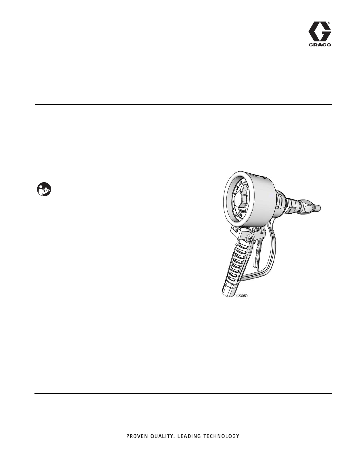
SDMM8 Manual Meter and
SDMP8 Preset Meter
333492B
For metered dispense of petroleum-based lubricants, oils and 50:50 antifreeze/water mix
fluids only.
For professional use only.
Maximum Working Pressure: 1500 psi (10 MPa, 103 bar)
List of Models page 2
Important Safety Instructions
Read all warnings and instructions in this
manual. Save these instructions.
EN
Page 2

Models
Models
SDMM8 Manual Bare Meters
Bare manual meters do not include a nozzle or extension. Model packages that include a nozzle and extension are
provided below.
Model Number Model Description Inlet
24U959* 4/16 Quart NPT
24U960* 4/16 Quart BSPT
24U961* 4/16 Quart BSPP
24U956* 4/16 Liter NPT
24U957* 4/16 Liter BSPT
24U958* 4/16 Liter BSPP
SDMM8 Manual Meters with Nozzle and Extension Packages
The following packages include Bare Meter Model 24U959 and the nozzle and extension kits indicated in the table
below.
Model Number Model Description Inlet Extension Nozzle/Extension Kit Nozzle Parts†
24V034 4/16 Quart NPT Flex 24V475 255459
24V037 4/16 Quart NPT Rigid 255852 255459
24V040 4/16 Quart NPT Gear Lube 255854 255470
The following packages include Bare Meter Model 24U960 and the nozzle and extension kits indicated in the table
below.
Model Number Model Description Inlet Extension Nozzle/Extension Kit Nozzle Parts†
24V035 4/16 Quart BSPT Flex 24V475 255459
24V038 4/16 Quart BSPT Rigid 255852 255459
24V041 4/16 Quart BSPT Gear Lube 255854 255470
The following packages include Bare Meter Model 24U961 and the nozzle and extension kits indicated in the table
below.
Model Number Model Description Inlet Extension Nozzle/Extension Kit Nozzle Parts†
24V036 4/16 Quart BSPP Flex 24V475 255459
24V039 4/16 Quart BSPP Rigid 255852 255459
24V042 4/16 Quart BSPP Gear Lube 255854 255470
The following packages include Bare Meter Model 24U956 and the nozzle and extension kits indicated in the table
below.
Model Number Model Description Inlet Extension Nozzle/Extension Kit Nozzle Parts†
24V043 4/16 Liter NPT Flex 24V475 255459
24V046 4/16 Liter NPT Rigid 255852 255459
24V049 4/16 Liter NPT Gear Lube 255854 255470
2 333492B
Page 3

Models
The following packages include Bare Meter Model 24U957 and the nozzle and extension kits indicated in the table
below.
Model Number Model Description Inlet Extension Nozzle/Extension Kit Nozzle Parts†
24V044 4/16 Liter BSPT Flex 24V475 255459
24V047 4/16 Liter BSPT Rigid 255852 255459
24V050 4/16 Liter BSPT Gear Lube 255854 255470
The following packages include Bare Meter Model 24U958 and the nozzle and extension kits indicated in the table
below.
Model Number Model Description Inlet Extension Nozzle/Extension Kit Nozzle Parts†
24V045 4/16 Liter BSPP Flex 24V475 255459
24V048 4/16 Liter BSPP Rigid 255852 255459
24V051 4/16 Liter BSPP Gear Lube 255854 255470
See Nozzle and Extension Kits, page 24
† See Nozzle Parts, page 25.
SDMP8 Preset Meters
Bare preset meters do not include a nozzle or extension. Model packages that include a nozzle and extension are
provided on page 4.
Model Number Model Description Inlet
24U947* 60 Quart NPT
24U948* 60 Quart BSPT
24U949* 60 Quart BSPP
24U950* 60 Gallon NPT
24U951* 60 Gallon BSPT
24U952* 60 Gallon BSPP
24U953* 60 Liter NPT
24U954* 60 Liter BSPT
24U955* 60 Liter BSPP
*This meter can be used for antifreeze applications with antifreeze nozzle 255855 or 24W306. See page 24 for information about these nozzles.
333492B 3
Page 4

Models
SDMP8 Preset Meters with Nozzle and Extension Packages
The following packages include Bare Meter Model 24U947 and the nozzle and extension kits indicated in the table
below.
Model Number Model Description Inlet Extension Nozzle/Extension Kit Nozzle Parts†
24V052 60 Quart NPT Rigid 24W641 255459
The following packages include Bare Meter Model 24U948 and the nozzle and extension kits indicated in the table
below.
Model Number Model Description Inlet Extension Nozzle/Extension Kit Nozzle Parts†
24V053 60 Quart BSPT Rigid 24W641 255459
The following packages include Bare Meter Model 24U949 and the nozzle and extension kits indicated in the table
below.
Model Number Model Description Inlet Extension Nozzle/Extension Kit Nozzle Parts†
24V054 60 Quart BSPP Rigid 24W641 255459
The following packages include Bare Meter Model 24U950 and the nozzle and extension kits indicated in the table
below.
Model Number Model Description Inlet Extension Nozzle/Extension Kit Nozzle Parts†
24V055 60 Gallon NPT Rigid 24W641 255459
The following packages include Bare Meter Model 24U951 and the nozzle and extension kits indicated in the table
below.
Model Number Model Description Inlet Extension Nozzle/Extension Kit Nozzle Parts†
24V056 60 Gallon BSPT Rigid 24W641 255459
The following packages include Bare Meter Model 24U952 and the nozzle and extension kits indicated in the table
below.
Model Number Model Description Inlet Extension Nozzle/Extension Kit Nozzle Parts†
24V057 60 Gallon BSPP Rigid 24W641 255459
The following packages include Bare Meter Model 24U953 and the nozzle and extension kits indicated in the table
below.
Model Number Model Description Inlet Extension Nozzle/Extension Kit Nozzle Parts†
24V058 60 Liter NPT Rigid 24W641 255459
The following packages include Bare Meter Model 24U954 and the nozzle and extension kits indicated in the table
below.
Model Number Model Description Inlet Extension Nozzle/Extension Kit Nozzle Parts†
24V059 60 Liter BSPT Rigid 24W641 255459
The following packages include Bare Meter Model 24U955 and the nozzle and extension kits indicated in the table
below.
Model Number Model Description Inlet Extension Nozzle/Extension Kit Nozzle Parts†
24V060 60 Liter BSPP Rigid 24W641 255459
See Nozzle and Extension Kits, page 24
† See Nozzle Parts, page 25.
4 333492B
Page 5
Warnings
WARNINGWARNINGWARNING
WARNING
Warnings
The following warnings are for the setup, use, grounding, maintenance, and repair of this equipment. The exclamation point symbol alerts you to a general warning and the hazard symbols refer to procedure-specific risks. When
these symbols appear in the body of this manual or on warning labels, refer back to these Warnings. Product-specific
hazard symbols and warnings not covered in this section may appear throughout the body of this manual where
applicable.
FIRE AND EXPLOSION HAZARD
When flammable fluids are present in the work area, such as gasoline and windshield wiper fluid, be
aware that flammable fumes can ignite or explode. To help prevent fire and explosion:
• Use equipment only in well ventilated area.
• Eliminate all ignition sources, such as cigarettes and portable electric lamps.
• Keep work area free of debris, including rags and spilled or open containers of solvent and gasoline.
• Do not plug or unplug power cords or turn lights on or off when flammable fumes are present.
• Ground all equipment in the work area.
• Use only grounded hoses.
• Stop operation immediately if static sparking occurs or you feel a shock. Do not use equipment
until you identify and correct the problem.
• Keep a working fire extinguisher in the work area.
SKIN INJECTION HAZARD
High-pressure fluid from dispensing device, hose leaks, or ruptured components will pierce skin. This
may look like just a cut, but it is a serious injury that can result in amputation. Get immediate surgical
treatment.
+
• Do not point dispensing device at anyone or at any part of the body.
• Do not put your hand over the fluid outlet.
• Do not stop or deflect leaks with your hand, body, glove, or rag.
• Follow the Pressure Relief Procedure when you stop dispensing and before cleaning, checking, or
servicing equipment.
• Tighten all fluid connections before operating the equipment.
• Check hoses and couplings daily. Replace worn or damaged parts immediately.
333492B 5
Page 6

Warnings
WARNINGWARNINGWARNING
WARNING
EQUIPMENT MISUSE HAZARD
Misuse can cause death or serious injury.
• Do not operate the unit when fatigued or under the influence of drugs or alcohol.
• Do not exceed the maximum working pressure or temperature rating of the lowest rated system
component. See Technical Data in all equipment manuals.
• Use fluids and solvents that are compatible with equipment wetted parts. See Technical Data in all
equipment manuals. Read fluid and solvent manufacturer’s warnings. For complete information
about your material, request MSDS from distributor or retailer.
• Do not leave the work area while equipment is energized or under pressure.
• Turn off all equipment and follow the Pressure Relief Procedure when equipment is not in use.
• Check equipment daily. Repair or replace worn or damaged parts immediately with genuine manufacturer’s replacement parts only.
• Do not alter or modify equipment. Alterations or modifications may void agency approvals and create
safety hazards.
• Make sure all equipment is rated and approved for the environment in which you are using it.
• Use equipment only for its intended purpose. Call your distributor for information.
• Route hoses and cables away from traffic areas, sharp edges, moving parts, and hot surfaces.
• Do not kink or over bend hoses or use hoses to pull equipment.
• Keep children and animals away from work area.
• Comply with all applicable safety regulations.
PRESSURIZED ALUMINUM PARTS HAZARD
Use of fluids that are incompatible with aluminum in pressurized equipment can cause serious chemical
reaction and equipment rupture. Failure to follow this warning can result in death, serious injury, or property damage.
• Do not use 1,1,1-trichloroethane, methylene chloride, other halogenated hydrocarbon solvents or
fluids containing such solvents.
• Many other fluids may contain chemicals that can react with aluminum. Contact your material supplier for compatibility.
PERSONAL PROTECTIVE EQUIPMENT
Wear appropriate protective equipment when in the work area to help prevent serious injury, including
eye injury, hearing loss, inhalation of toxic fumes, and burns. This protective equipment includes but is
not limited to:
• Protective eyewear, and hearing protection.
• Respirators, protective clothing, and gloves as recommended by the fluid and solvent manufacturer
6 333492B
Page 7

Typical Installation
L
R
M
N
P
H
J
G
F
A
K
D
E
C
B
S
Typical Installation
FIG. 1
Key:
A Main air supply line
B Pump air supply line
CAir filter
D Air regulator
E Bleed-type master air valve (required)
FPump
G Pump grounding wire (required)
H Pressure relief valve (required)
NOTE: The relief pressure cannot exceed the meter’s maximum working pressure
J Fluid shut off valve
K Fluid line
L Fluid shut off valve
M Hose reel
N SDMM8 or SDMP8 meter
P Mounting channel
R Hose reel fluid inlet kit
S Fluid drain valve
333492B 7
Page 8
Installation
Installation
NOTE: The letters used in the following instructions
refer to Typical Installation on page 7.
Pressure Relief Procedure
Follow the Pressure Relief Procedure whenever
you see this symbol.
This equipment stays pressurized until pressure is
manually relieved. To help prevent serious injury from
pressurized fluid, such as skin injection, splashing
fluid and moving parts, follow the Pressure Relief
Procedure when you stop spraying and before
cleaning, checking, or servicing the equipment.
1. Turn off power supply to the pump or close
upstream master air valve (E).
2. Open all fluid shut off valves (J and L) in the system.
3. Trigger the meter (N) into a waste container to
relieve pressure.
4. Open fluid drain valves and leave them open until
you are ready to pressurize the system.
Grounding
• The equipment must be grounded to reduce the
risk of static sparking. Static sparking can cause
fumes to ignite or explode. Grounding provides
an escape wire for the electric current.
• To prevent electric arcing do not allow the
conductive metal surfaces on the meter to make
contact with any positively charged metal
surface, including (but not limited to), the starter
solenoid terminal, alternator terminal or battery
terminal.
Ground all components in the system:
Pump (F): Follow manufacturer’s recommendations.
Air and fluid supply lines (A, B, K): Only use electri-
cally conductive hoses. Check electrical resistance of
hoses. If total resistance to ground exceeds 29 megohms, replace hose immediately.
Air compressor: Follow manufacturer’s recommendations.
Fluid supply container: Follow local code.
To maintain grounding continuity when flushing or
relieving pressure: hold a metal part of the meter firmly
to the side of a grounded metal pail, then trigger the
valve.
SDMM8 and SDMP8 Meter (N): When installing the
meter leave at least two threads bare when using thread
sealant. The bare threads ensure a ground is maintained.
8 333492B
Page 9

Component Identification
1
12
41
37
102
101
Installation
FIG. 2
Key:
1 Swivel
12 Trigger
37 Meter dial
41 Meter pointer
101 Nozzle
102 Extension
333492B 9
Page 10

Installation
1
N
Pre-Installation Procedure
NOTE: The letters used in the following instructions
refer to Typical Installation on page 7 and the Component Identification on page 9. Numbers used in the following instructions refer to the Parts List on pages 19 -
21.
1. Relieve pressure, page 8.
2. Close all fluid drain valves.
3. Ground all equipment as instructed on page 8.
Installation Procedure
NOTICE
• If this is a new installation or if the fluid lines are
contaminated, flush the lines before you install the
metered valve. Contaminated lines could cause the
valve to leak.
• Never dispense compressed air with meter. Doing
so will damage meter.
4. Slowly open the fluid shut off valve (J).
5. If you have multiple dispense positions, first flush
the dispense position farthest from the pump and
work your way toward the pump. Slowly open the
fluid shut-off valve (L) at the dispense position.
Flush out a sufficient amount of oil to ensure that the
entire system is clean; then close the valve.
6. Repeat Step 5 at all other positions.
Installing Meter (FIG. 3)
)
1. If this is a new installation and the first time a meter
is installed, skip step 1.
For existing installations, to replace the meter (N):
a. Relieve pressure, page 8.
b. Use two wrenches working in opposite direc-
tions to loosen meter and hose fitting. Remove
meter (N) from hose.
Flushing
NOTE: The meter should not be installed for this proce-
dure.
1. Close the fluid shut-off valve (L) at each dispense
position.
2. Make sure:
• all fluid drain valves are closed,
• fluid shut off valve (J) is closed,
and
• the bleed-type master air valve (E) is open.
3. Place the end of the hose into a container for waste
oil. Secure the hose in the container so it will not
come out during flushing.
FIG. 3
2. Apply thread sealant to the male threads of the hose
fitting. Leave at least two threads bare when using
thread sealant. The bare threads ensure a ground is
maintained.
3. Thread the meter swivel (1) onto the hose fitting.
Use two wrenches working in opposite directions to
tighten meter securely to hose fitting.
NOTE: Make sure you allow sufficient time for the sealant to cure to the manufacturer’s recommendations
before circulating fluid through the system.
10 333492B
Page 11

Installation
102a
102
102
101
102
101a
4. Install extension (102) to meter:
a. Loosen extension nut (102a) (F
IG. 4) until it is
completely off tube threads.
FIG. 4
NOTE: Do not use PTFE tape or thread sealant on
threads of extension (102). This could cause the fitting
to leak.
b. Thread extension (102) into meter housing as
shown in F
IG. 5 until it bottoms out.
d. Wrench tighten extension nut (102a).
5. Install nozzle (101):
NOTE: Do not use PTFE tape or thread sealant on
threads of nozzle (101). This could cause the fitting to
leak.
a. Thread nozzle (101) onto extension (102) as
.
shown in F
IG. 7.
FIG. 5
c. Align extension (102) with meter housing and
handle. Hand tighten extension nut (102a).
FIG. 7
b. Use an open-end adjustable wrench on flats of
nozzle bushing (101a) (F
IG. 7) to tighten fitting.
• Only tighten nozzle with wrench on flats of the
nozzle bushing.
• Do not disassemble the bushing from noz-
zle. Disassembly will affect performance of the
nozzle.
FIG. 6
333492B 11
Page 12

Operation
41
41
Operation
NOTE: The letters used in the following instructions
refer to Typical Installation on page 7 and the Component Identification on page 9. Numbers used in the following instructions refer to the Parts List on pages 19 -
21.
1. Open fluid shut off valves (J and L).
2. Start pump (F) to pressurize system.
3. Adjust the air pressure to the pump motor so the
fluid pressure is no greater than 1500 psi (103.4
bar, 10.34 MPa)
NOTE: To ensure dispensing accuracy, before beginning dispense, pull trigger to purge all air from the fluid
lines and meter.
4. Continue operation with instructions for Preset Automatic or Manual Shutoff Valve Instructions.
The totalizer keeps a running total of the amounts dispensed.
1. Turn meter pointer (41) counter-clockwise to select
the desired volume.
2. Turn automatic twist lock nozzle (101) clockwise to
open nozzle. Insert nozzle into the fluid receptacle
and pull the trigger (12).
NOTE: The trigger latches automatically. Do not set
trigger to enable meter to dispense when it is unattended.
The meter shuts off automatically when the set amount
of fluid is dispensed.
Manual Shutoff Valve
NOTE: Clean strainer (3a) regularly. See Parts, page
21.
SPLASH HAZARD
Do not trigger meter when nozzle is closed. Fluid
will build up behind the nozzle. Fluid can leak from
the nozzle and can unexpectedly be expelled when
the nozzle is opened. If the meter is accidentally triggered with the nozzle closed, point the nozzle into a
waste bucket and slowly open the nozzle to relieve
pressure and expel the built up fluid.
Preset Automatic Shutoff
NOTE: Clean strainer (3a) regularly. See Parts, page
19.
NOTICE
To avoid costly meter damage, never turn the Preset
meter pointer (41) (F
FIG. 8
IG. 8) backwards (clockwise).
NOTICE
To avoid costly meter damage, never turn the Manual
Meter pointer (41) backwards (clockwise).
FIG. 9
The totalizer keeps a running total of the amounts dispensed.
1. Turn automatic twist lock nozzle (101) counterclockwise to open nozzle. Insert nozzle into the fluid
receptacle and pull the trigger (12).
2. Watch the meter pointer (41) on the meter dial (37)
move. Release the trigger (12) when the desired
amount of fluid has been dispensed.
3. Turn the meter pointer (41) counter-clockwise to
return it to “0” before dispensing again. See F
IG. 9
12 333492B
Page 13

Troubleshooting
Troubleshooting
Relieve pressure, page 8, before you check or repair the meter. Be sure all other valves, controls and pump are
operating properly.
Problem Cause Solution
1. Relieve pressure, page 8.
2. Remove meter from hose.
3. Clean or replace strainer (3a).
Slow or no fluid flow.
Meter leaks from twist lock nozzle.
• It is important to distinguish
between the two causes of this
problem. A new nozzle will NOT
correct a fluid leak caused by a
faulty valve.
Strainer (3a) is clogged.
Pump pressure is low. Increase pump pressure.
Twist lock nozzle not fully open. Aim nozzle into bucket. Fully open noz-
Fluid shut-off valve (J or L) is not fully open
(page 9).
Foreign material is wedged in the meter
housing.
Twist lock nozzle has a damaged seal. Replace nozzle. See Step a in Installa-
Valve has damaged or obstructed seals. Clean valve assembly or replace.
4. Install meter to hose (See Installing
Meter, page 10).
5. If the problem remains, contact your
Graco distributor for repair or
replacement.
zle.
Do not trigger meter when nozzle is
closed! If you do accidentally trigger
the meter with the nozzle closed, point
nozzle into a waste bucket and slowly
open the nozzle to relieve pressure and
expel built up fluid.
Fully open fluid shut-off valve (J or L).
Contact your Graco distributor for repair
or replacement.
tion Procedure, page 11.
Poor swivel/hose connection. Apply PTFE tape (leave a minimum 2
engaged threads uncovered for electrical continuity) or sealant to threads of
hose and tighten the connection. See
Meter leaks from swivel.
Poor swivel/meter housing connection. Torque the fitting to 20-25 ft.-lbs.
Swivel seals have deteriorated and leak. Replace swivel.
333492B 13
Step 2 in Installation Procedure, page
10.
Page 14

Service
101
102
17
18
19
19
19d
Service
Cleaning / Repairing the Fluid Section
NOTE: Do not disassemble the fluid and counting sec-
tions simultaneously. Confirm the fluid section is fully
assembled before removing the counting section.
1. Relieve pressure, page 8.
2. Close fluid shut off valve (L).
3. Remove nozzle (101) and extension (102).
5. Remove seal (18) and piston assembly (19). If the
piston assembly sticks, lightly tap the housing
against a flat surface to loosen it (F
FIG. 12
6. Insert a screwdriver into the notch of the piston
assembly (19) and pry off the piston cover (19d).
See F
IG. 13. Remove all parts.
IG. 12).
FIG. 10
4. Turn meter cap (17) counter-clockwise to unscrew
and remove it from the meter housing.
FIG. 11
14 333492B
FIG. 13
7. Clean the parts (19a-g) and blow them dry.
8. Reassemble the piston assembly (19) and install in
meter.
9. Install cover (17) on meter housing. Torque to 11-14
ft. lbs (14.9-18.9 N•m).
10. Install nozzle and extension assembly (101 and
102).
Page 15

Service
44
42
43
41
41
39/40
50
52
51
53
38
37
33
34
32
35
SDMM8 Manual Meter Counter Section Repair
Disassembly
NOTE: Do not disassemble the fluid and counting sec-
tions simultaneously. Confirm the fluid section is fully
assembled before removing the counting section.
1. Relieve pressure, page 8.
2. Remove the cover (44), small retaining ring (43),
pointer pin (41) and pointer spring (42) (F
IG. 14).
4. Use a hex wrench to remove the plug setscrew.
Remove the plug (50), remove the pin (51), spring
(53), and the lower pointer (52) (F
FIG. 16
5. Remove the large retaining clip (38) and then the
face plate panel (37) (F
IG. 17).
IG. 16).
FIG. 14
3. Remove the needle pointer (41), springs (39) and
pins (40) (F
FIG. 15
IG. 15).
FIG. 17
6. Use a 2 mm hex wrench to remove the gear setscrew (33). Remove the gears (32, 34, 35) (F
FIG. 18
IG. 18).
333492B 15
Page 16

Service
31
31
33
34
32
35
38
37
50
52
51
53
41
39/40
7. Remove the entire counter assembly (31) (FIG. 19).
FIG. 19
Reassembly
1. Install counter assembly (31).
3. Install the face plate panel (37) and large retaining
clip (38) (F
IG. 22).
FIG. 22
4. Install the lower pointer (52), spring (53), pin (51)
and plug (50) as shown in F
IG. 23. Use a hex
wrench to tighten the plug setscrew.
FIG. 20
2. Install the gears (32, 34, 35) as shown in F
Use a 2 mm hex wrench to tighten the gear setscrew (33).
FIG. 21
IG. 21.
FIG. 23
5. Install the needle pointer (41), springs (39) and pins
(40) as shown in F
IG. 24.
FIG. 24
16 333492B
Page 17

Service
44
42
43
41
44
43
41
39/40
38
37
33
34
32
6. Install small retaining ring (43), pointer pin (41) and
pointer spring (42). Install the cover (44). (F
FIG. 25
IG. 25).
SDMP8 Preset Meter Counter Section Repair
Disassembly
NOTE: Do not disassemble the fluid and counting sec-
tions simultaneously. Confirm the fluid section is fully
assembled before removing the counting section.
3. Remove the needle pointer (41), springs (39) and
pins (40) (F
FIG. 27
4. Remove the large retaining clip (38) and then the
face plate panel (37) (F
IG. 27).
IG. 28).
1. Relieve pressure, page 8.
2. Remove the cover (44), small retaining ring (43),
(F
IG. 26).
FIG. 26
333492B 17
FIG. 28
5. Use a 2 mm hex wrench to remove the gear setscrew (33). Remove the gears (32, 34) (F
FIG. 29
IG. 29).
Page 18

Service
31
31
33
34
32
38
37
41
39/40
44
43
6. Remove the entire counter assembly (31) (FIG. 30).
FIG. 30
Reassembly
1. Install counter assembly (31) (FIG. 31).
3. Install face plate panel (37) and large retaining clip
(38) (F
IG. 33).
FIG. 33
4. Install the needle pointer (41), springs (39) and pins
(40) as shown in F
IG. 34.
FIG. 31
2. Install the gears (32, 34). Use a 2 mm hex wrench to
tighten gear set screw (33). (F
IG. 32).
FIG. 32
FIG. 34
5. Install small retaining ring (43) and cover (44) (F
35).
FIG. 35
IG.
18 333492B
Page 19

SDMM8 Manual Meter Parts
1
3b
3a
5
8
6
9
10
11
2
16
12
13
14
15
16
46
49
45
47
48
29
33
32
37
31
38
36
35
34
40
39
41
43
51
42
28
19g
19f
19d
19c
19b
18
17
44
19a
7
14
15
19
See Ref A
Ref A
Ref B
See
Ref B
39
40
Torque to 7-10 ft lbs (9-13 N.m)
1
Torque to 15-25 in. lbs (1.7-2.8 N.m)
2
Torque to 11-14 ft. lbs (14.9-18.9 N.m)
3
3
1
2
2
39
40
50
52
33
Models 24U959, 24U960, 24U961, 24U956,
24U957, 24U958
SDMM8 Manual Meter Parts
333492B 19
Page 20

SDMM8 Manual Meter Parts
SDMM8 Manual Meter Parts
Models 24U959, 24U960, 24U961, 24U956, 24U957, 24U958
Ref Part No. Description Qty
1 SWIVEL 1
238399 model 24U959, 24U956
24H383 model 24U960, 24U957
24H382 model 24U961, 24U958
2 HOUSING, meter 1
3 256164 KIT, strainer, includes 3a
and 3b
3a STRAINER 10
3b WASHER, plain 10
5 113493 SPRING, compression 1
6 15U704 SEAT, valve 1
7 15U701 SPRING, secondary 1
8 15U700 PLUNGER, trigger lift 1
9 16X485 SEAT, valve 1
10 121412 O-RING, pack 1
11 277673 ROD, push 1
12 15M886 TRIGGER 1
13 191315 CAM 1
14 113574 SEAL, o-ring 2
15 191552 WASHER, flat 2
16 110637 SCREW, mach, panhead 2
17 16X493 CAP, housing 1
18 156633 PACKING, o-ring 1
19 KIT, piston, includes
19a-19g
24V470 QUARTS, models
24U959, 24U960,
24U961
24V471 LITERS, models 24U956,
24U957, 24U958
19a PISTON, chamber 1
19b PISTON, oscillating 1
19c DIVIDER 1
19d GEAR, cover 1
19e ROLLER (not shown) 1
Ref Part No. Description Qty
19f GEAR, 10 teeth 1
19g GEAR, 21 teeth 1
28 24V467 KIT, SHAFT 1
29 106560 PACKING, o-ring 1
31 24U352 COUNTER 1
1
1
32 16X595 GEAR, worm-spur 1
33† 16X589 SCREW, setting M4 x 6 2
34 16X588 GEAR. twins, 14-32 1
35 16X586 GEAR, 42 teeth 1
36 16X491 COVER, protector 1
37 DIAL 1
16X597 models 24U959, 24U960,
16X596 models 24U956, 24U957,
38 16X498 CLIP, ring 1
39† 16X583 SPRING, inner and outer 3
40† 16X592 PIN, inner and outer 3
41† 16X576 NEEDLE, upper 1
42† 16X584 SPRING, outer, pointer 1
43† 17B784 RING, retaining 1
44† 16X575 COVER, needle 1
45 15R013 LATCH, lever 1
46 15R014 SPRING, latch 1
47 15R015 LATCH, arm 1
48 15R016 LATCH, pin 1
49 114680 PIN, dowel 1
50† 16X580 PLUG 1
51† 16X582 PIN, outer pointer 1
52† 16X578 NEEDLE, lower, casting 1
53† 16X601 SPRING (not shown)
Parts are included in Kit 24V460
† Parts are included in Kit 24V474
Parts are included in Kit 24V473
24U961
24U958
1
20 333492B
Page 21

SDMP8 Preset Meter Parts
44
41
42
50
34
40
39
35
38
45
46
49
47
43a
48
1
3b
3a
5
8
6
9
10
11
2
12
14
15
16
13
16
28
33
32
31
37
30
19g
19f
19c
19b
18
17
15
14
19d
19a
7
19
See Ref A
Ref A
Ref B
39
40
51
See
Ref B
Torque to 7-10 ft lbs (9-13 N.m)
1
Torque to 15-25 in. lbs (1.7-2.8 N.m)
2
Torque to 11-14 ft. lbs (14.9-18.9 N.m)
3
3
2
2
1
43b
52
SDMP8 Preset Meter Parts
Models 24U947, 24U948, 24U949, 24U950, 24U951, 24U952, 24U953, 24U954, 24U955
333492B 21
Page 22

SDMP8 Preset Meter Parts
SDMP8 Preset Meter Parts
Models 24U947, 24U948, 24U949, 24U950, 24U951, 24U952, 24U953, 24U954, 24U955
Ref Part No. Description Qty
1SWIVEL
238399 model 24U947, 24U950,
24U953
24H383 model 24U948, 24U951,
24U954
24H382 model 24U949, 24U952,
24U955
2 HOUSING, meter
3 256164 KIT, strainer, includes 3a
and 3b
3a STRAINER 1
3b WASHER, plain 1
5 113493 SPRING, compression
6 15U704 SEAT, valve
7 15U701 SPRING, secondary
8 15U700 PLUNGER, trigger lift
9 16X485 SEAT, valve
10 121412 O-RING, packing
11 277673 ROD, push
12 16Y317 TRIGGER
13 16X497 CAM
14 113574 SEAL, o-ring
15 191552 WASHER, flat
16 110637 SCREW, mach, panhead
17 16X494 CAP, housing
18 156633 PACKING, o-ring
19 KIT, piston, includes
19a-19h
24V470 QUARTS, models 24U947,
24U948, 24U949
GALLONS, models
24U950, 24U951, 24U952
Ref Part No. Description Qty
1
1
1
1
1
1
1
1
1
1
1
1
2
2
2
1
1
1
19b PISTON, oscillating 1
19c DIVIDER 1
19d PISTON, chamber 1
19e ROLLER (not shown) 1
19f GEAR, 10 teeth 1
19g GEAR, 21 teeth 1
28 106560 PACKING, o-ring
30 KIT, shaft
24V468 models 24U947, 24U948,
24U949, 24U953, 24U954,
24U955
24V469 models 24U950, 24U951,
24U952
31 COUNTER
24U354 model 24U947, 24U948,
24U949
24U353 model 24U950, 24U951,
24U952
24U352 model 24U953, 24U954,
24U955
32 GEAR, worm-spur
‡ 16X594 models 24U947, 24U948,
24U949, 24U950, 24U951,
24U952
16X593 models 24U953, 24U954,
24U955
33‡ 16X589 SCREW, setting
34 16X585 GEAR, 45 teeth
35 16X490 COVER
1
1
1
1
1
1
1
24V471 LITERS, models 24U953,
24U954, 24U955
19a GEAR, cover 1
22 333492B
Page 23

SDMP8 Preset Meter Parts
Ref Part No. Description Qty
36 16X587 GEAR, twin 11-44 teeth
(not shown) Models
24U947, 24U948, 24U949,
24U953, 24U954, 24U955
16Y999 GEAR, twin 24-44 teeth
(not shown) Models
24U950, 24U951, 24U952
16X588 GEAR. twins, 14-32, (not
shown) Models 24U950,
24U951, 24U952
17A029 GEAR, 11-42 teeth (not
shown) Models 24U950,
24U951, 24U952
37 DIAL
16X599 model 24U947, 24U948,
24U949
16X600 model 24U950, 24U951,
24U952
16X598 model 24U953, 24U954,
24U955
38 16X498 CLIP, ring
39 16X583 SPRING, inner and outer
pointer
Ref Part No. Description Qty
1
40 16X581 PIN, inner and outer
pointer
41 16X577 NEEDLE
1
42 16X584 SPRING, outer pointer
43 RING, retaining
43a 16X611
1
43b 17B784
44 16X575 COVER, needle
1
45 16X606 BRACKET, valve, trigger
46 16X607 PIN, screw
1
47 16X613 SPRING, lock, pawl
48 PIN, lock, pawl
49 16X610 LOCK, pawl
50 16X579 NEEDLE, plate
51 16X590 PIN
52 16X492 TRIGGER, guard
1
‡ Included in Kit 24V466
Included in Kit 24V472
2
Included in Kit 24V465
Included in Kit 24V461
2
1
1
1
1
1
1
1
1
1
1
1
1
1
333492B 23
Page 24

Nozzle (101) and Extension (102) Kits
Nozzle (101) and Extension (102) Kits
Kit No. Description Fluid Type
255852*
24V475*
24W641*
255854
Automatic, non-drip quick close nozzle with
rigid extension
Automatic, non-drip quick close nozzle with
flexible extension
Automatic, non-drip quick close nozzle with
short rigid extension
Non-drip, quick close nozzle with rigid
extension
Oil
Oil
Oil
Gear Lube
255855*
24W306*
*Used for dispensing 5gpm (22.7 lpm) or less.
24 333492B
Non-drip, quick close nozzle with rigid
extension
Non-drip, quick close nozzle with flexible
extension
Antifreeze
Antifreeze
Page 25

Nozzle (101) Parts
Part No. Description Qty Fluid Type
255459* Automatic, non-drip, quick-close nozzle Oil
• BODY, nozzle 1
• O-RING, packing 1
• SPRING, compression 1
• O-RING, packing 1
• STEM, nozzle, valve 1
• SEAT, valve 1
255460* Automatic, non-drip, quick-close nozzle Antifreeze
• BODY, nozzle 1
• SPRING, compression 1
• O-RING, packing 1
• STEM, nozzle, valve 1
• O-RING, packing 1
• SEAT, valve 1
255470 Non-drip, quick-close nozzle Gear Lube
• Housing 1
• Body, nozzle 1
• O-RING, packing 1
• O-RING, packing 1
• Plug, Hollow, hex 1
Nozzle (101) Parts
*Used for dispensing 5gpm (22.7 lpm) or less.
333492B 25
Page 26

Technical Data
Technical Data
Manual and Preset Meter
US Metric
Flow rate* 0.26 to 8 gpm 1 to 30 lpm
Maximum working pressure 1500 psi 10 MPa, 103.4 bar
Weight
Manual Meter 3.42 lbs 1.55 kg
Preset Meter 3.50 lbs 1.58 kg
Dimensions (without extension) (see page 27)
Length 11.4 inches 28.9 cm
Width 3.94 inches 10 cm
Height Manual Meter 4.85 inches 12.3 cm
Height Preset Meter 6.33 inches 16.08 cm
Maximum Totalizer Digits 99,999 units**
Inlet 1/2-14 NPT
1/2-14 BSPP
1/2-14 BSPT
Outlet 3/4-16 straight thread o-ring boss
Operating temperature range -50 °F to 160°F -45°C to 70°C
Wetted parts brass, aluminum, stainless steel, TPE
Fluid compatibility antifreeze, gear oil, crankcase oil
Meter pressure loss 30 psi @ 4 gpm
Accuracy - Manual Meter: Oil +/- 1 percent
Accuracy - Manual Meter: Antifreeze +/- 3 percent
Accuracy - Preset Meter: Oil or Antifreeze +/- 3 percent
*Tested in 10W motor oil. Flow rates vary with fluid pressure, temperature and viscosity.
**Rolls over to 00,000 after maximum value is reached.
26 333492B
Page 27

Dimensions
Manual Meter Preset Meter
Technical Data
FIG. 36
333492B 27
FIG. 37
Page 28

Graco Extended Meter Warranty
Graco warrants all equipment referenced in this document which is manufactured by Graco and bearing its name to be free from defects in
material and workmanship on the date of sale to the original purchaser for use. Graco will, for a period of five (5) years from the date of sale, repair
or replace any non-wear parts of the equipment determined by Graco to be defective. Graco will also for a period of one (1) year from the date of
sale, repair, or replace any wear parts of the equipment determined by Graco to be defective. This warranty applies only when the equipment is
installed, operated and maintained in accordance with Graco's written recommendations.
This warranty does not cover, and Graco shall not be liable for general wear and tear, or any malfunction, damage or wear caused by faulty
installation, misapplication, abrasion, corrosion, inadequate or improper maintenance, negligence, accident, tampering, or substitution of
non-Graco component parts. Nor shall Graco be liable for malfunction, damage or wear caused by the incompatibility of Graco equipment with
structures, accessories, equipment or materials not supplied by Graco, or the improper design, manufacture, installation, operation or
maintenance of structures, accessories, equipment or materials not supplied by Graco.
This warranty is conditioned upon the prepaid return of the equipment claimed to be defective to an authorized Graco distributor for verification of
the claimed defect. If the claimed defect is verified, Graco will repair or replace free of charge any defective parts. The equipment will be returned
to the original purchaser transportation prepaid. If inspection of the equipment does not disclose any defect in material or workmanship, repairs
will be made at a reasonable charge, which charges may include the costs of parts, labor, and transportation.
THIS WARRANTY IS EXCLUSIVE, AND IS IN LIEU OF ANY OTHER WARRANTIES, EXPRESS OR IMPLIED, INCLUDING BUT NOT
LIMITED TO WARRANTY OF MERCHANTABILITY OR WARRANTY OF FITNESS FOR A PARTICULAR PURPOSE.
Graco’s sole obligation and buyer’s sole remedy for any breach of warranty shall be as set forth above. The buyer agrees that no other remedy
(including, but not limited to, incidental or consequential damages for lost profits, lost sales, injury to person or property, or any other incidental or
consequential loss) shall be available. Any action for breach of warranty must be brought within two (2) years of the date of sale.
GRACO MAKES NO WARRANTY, AND DISCLAIMS ALL IMPLIED WARRANTIES OF MERCHANTABILITY AND FITNESS FOR A
PARTICULAR PURPOSE, IN CONNECTION WITH ACCESSORIES, EQUIPMENT, MATERIALS OR COMPONENTS SOLD BUT NOT
MANUFACTURED BY GRACO. These items sold, but not manufactured by Graco (such as electric motors, switches, hose, etc.), are subject to
the warranty, if any, of their manufacturer. Graco will provide purchaser with reasonable assistance in making any claim for breach of these
warranties.
In no event will Graco be liable for indirect, incidental, special or consequential damages resulting from Graco supplying equipment hereunder, or
the furnishing, performance, or use of any products or other goods sold hereto, whether due to a breach of contract, breach of warranty, the
negligence of Graco, or otherwise.
FOR GRACO CANADA CUSTOMERS
The Parties acknowledge that they have required that the present document, as well as all documents, notices and legal proceedings entered into,
given or instituted pursuant hereto or relating directly or indirectly hereto, be drawn up in English. Les parties reconnaissent avoir convenu que la
rédaction du présente document sera en Anglais, ainsi que tous documents, avis et procédures judiciaires exécutés, donnés ou intentés, à la suite
de ou en rapport, directement ou indirectement, avec les procédures concernées.
Graco Information
For the latest information about Graco products, visit www.graco.com.
TO PLACE AN ORDER, contact your Graco distributor or call to identify the nearest distributor.
Phone: 612-623-6928 or Toll Free: 1-800-533-9655, Fax: 612-378-3590
All written and visual data contained in this document reflects the latest product information available at the time of publication.
GRACO INC. AND SUBSIDIARIES • P.O. BOX 1441 • MINNEAPOLIS MN 55440-1441 • USA
Copyright 2014, Graco Inc. All Graco manufacturing locations are registered to ISO 9001.
Graco reserves the right to make changes at any time without notice.
Original instructions. This manual contains English. MM 333492
Graco Headquarters: Minneapolis
International Offices: Belgium, China, Japan, Korea
www.graco.com
November 2014
 Loading...