

Page 1

Instructions
®
Dyna-Star
HP and
HF Pump AC to DC
333391B
Conversion Kit
EN
Kit to convert an AC Power Source to a DC Power Source. For use with the Electric
Dyna-Star HP and HF Pump only. Not approved for outdoor use. For professional use only.
Not approved for use in explosive atmospheres or hazardous locations.
Part No.: 77X524
Important Safety Instructions
Read all warnings and instructions in this
manual and in the Dyna-Star HP and HF
Pump instruction manual. Save all instructions.
Table of Contents
Warnings . . . . . . . . . . . . . . . . . . . . . . . . . . . . . . . . . . . . . . . . . . . . 2
Typical Installation . . . . . . . . . . . . . . . . . . . . . . . . . . . . . . . . . . . . 3
Installation . . . . . . . . . . . . . . . . . . . . . . . . . . . . . . . . . . . . . . . . . . . 4
Dyna-Star Pump Current Control Adjustment . . . . . . . . . . . . . 4
Enclosure Preparation . . . . . . . . . . . . . . . . . . . . . . . . . . . . . . 5
Controller Cord Grip Installation . . . . . . . . . . . . . . . . . . . 5
Pressure Switch Cord Grip . . . . . . . . . . . . . . . . . . . . . . . 5
Electric Dyna-Star Cord Grip . . . . . . . . . . . . . . . . . . . . . 6
Controller Installation . . . . . . . . . . . . . . . . . . . . . . . . . . . . . . . 6
GLC2200 . . . . . . . . . . . . . . . . . . . . . . . . . . . . . . . . . . . . 6
GLC2200 Installation . . . . . . . . . . . . . . . . . . . . . . . . . . . 7
Installing Enclosure to Mounting Surface . . . . . . . . . . . . . . . . 7
Fuse Installation . . . . . . . . . . . . . . . . . . . . . . . . . . . . . . . . . . . 7
Fuses . . . . . . . . . . . . . . . . . . . . . . . . . . . . . . . . . . . . . . . 7
Connecting Power Supply . . . . . . . . . . . . . . . . . . . . . . . . . . . . 9
System Configuration and Wiring . . . . . . . . . . . . . . . . . . 9
Instructions . . . . . . . . . . . . . . . . . . . . . . . . . . . . . . . . . . . 9
Dyna-Star Pump Connections . . . . . . . . . . . . . . . . . . . . 9
Controller Connection . . . . . . . . . . . . . . . . . . . . . . . . . . 10
LEVER-NUTS
Installing Power Cord Clamp . . . . . . . . . . . . . . . . . . . . 10
Installing Power Cord . . . . . . . . . . . . . . . . . . . . . . . . . . 12
Kit 77X524 Parts . . . . . . . . . . . . . . . . . . . . . . . . . . . . . . . . . . . . . 13
Enclosure Parts . . . . . . . . . . . . . . . . . . . . . . . . . . . . . . . . . . . 13
Kit 77X524 Inside Enclosure Parts . . . . . . . . . . . . . . . . . . . . 14
Technical Data . . . . . . . . . . . . . . . . . . . . . . . . . . . . . . . . . . . . . . . 15
Enclosure Mounting Dimensions . . . . . . . . . . . . . . . . . . . . . 15
Cord Grip/Cable Gland Dimensions . . . . . . . . . . . . . . . . . . . 16
Bottom View . . . . . . . . . . . . . . . . . . . . . . . . . . . . . . . . . 16
Side View . . . . . . . . . . . . . . . . . . . . . . . . . . . . . . . . . . . 16
Notes . . . . . . . . . . . . . . . . . . . . . . . . . . . . . . . . . . . . . . . . . . . . . . 17
Graco Standard Warranty . . . . . . . . . . . . . . . . . . . . . . . . . . . . . 18
®
. . . . . . . . . . . . . . . . . . . . . . . . . . . . . . . 10
Page 2
Warnings
WARNINGWARNINGWARNING
WARNING
Warnings
The following warnings are for the setup, use, grounding, maintenance, and repair of this equipment. The exclamation point symbol alerts you to a general warning and the hazard symbols refer to procedure-specific risks. When
these symbols appear in the body of this manual or on warning labels, refer back to these Warnings. Product-specific
hazard symbols and warnings not covered in this section may appear throughout the body of this manual where
applicable.
ELECTRIC SHOCK HAZARD
This equipment must be grounded. Improper grounding, setup, or usage of the system can cause
electric shock.
• Turn off and disconnect power at main switch before disconnecting any cables and before servicing
or installing equipment.
• Connect only to grounded power source.
• All electrical wiring must be done by a qualified electrician and comply with all local codes and
regulations.
EQUIPMENT MISUSE HAZARD
Misuse can cause death or serious injury.
• Do not operate the unit when fatigued or under the influence of drugs or alcohol.
• Do not exceed the maximum working pressure or temperature rating of the lowest rated system
component. See Technical Data in all equipment manuals.
• Use fluids and solvents that are compatible with equipment wetted parts. See Technical Data in all
equipment manuals. Read fluid and solvent manufacturer’s warnings. For complete information
about your material, request MSDS from distributor or retailer.
• Turn off all equipment and follow the Pressure Relief Procedure in you pump manual when equip-
ment is not in use.
• Check equipment daily. Repair or replace worn or damaged parts immediately with genuine manufacturer’s replacement parts only.
• Do not alter or modify equipment. Alterations or modifications may void agency approvals and create
safety hazards.
• Make sure all equipment is rated and approved for the environment in which you are using it.
• Use equipment only for its intended purpose. Call your distributor for information.
• Route hoses and cables away from traffic areas, sharp edges, moving parts, and hot surfaces.
• Do not kink or over bend hoses or use hoses to pull equipment.
• Keep children and animals away from work area.
• Comply with all applicable safety regulations.
PERSONAL PROTECTIVE EQUIPMENT
Wear appropriate protective equipment when in the work area to help prevent serious injury, including
eye injury, hearing loss, inhalation of toxic fumes, and burns. This protective equipment includes but is
not limited to:
• Protective eye wear, and hearing protection.
• Respirators, protective clothing, and gloves as recommended by the fluid and solvent manufacturers.
2 333391B
Page 3

Typical Installation
A
B
C
F
E
G
H
J
K
L
D
K
Typical Installation
A AC to DC Kit Enclosure
B Dyna-Star Pump*
C Fluid Drum*
D GLC2200* (24N468)
E GLC2200 Connector
F Cable Gland Kit (77X533)
G Pressure Switch Connection (Optional)
H Power Cord - 9 feet (2.7 meters)
J GLC2200* (wall installation)
K Electric Dyna-Star Power Cord and Cable Kits* (77X527, 77X528)
L GLC2200 Cable* (24P686)
*User supplied
333391B 3
Page 4
Installation
116
120
119
116
120
119
Installation
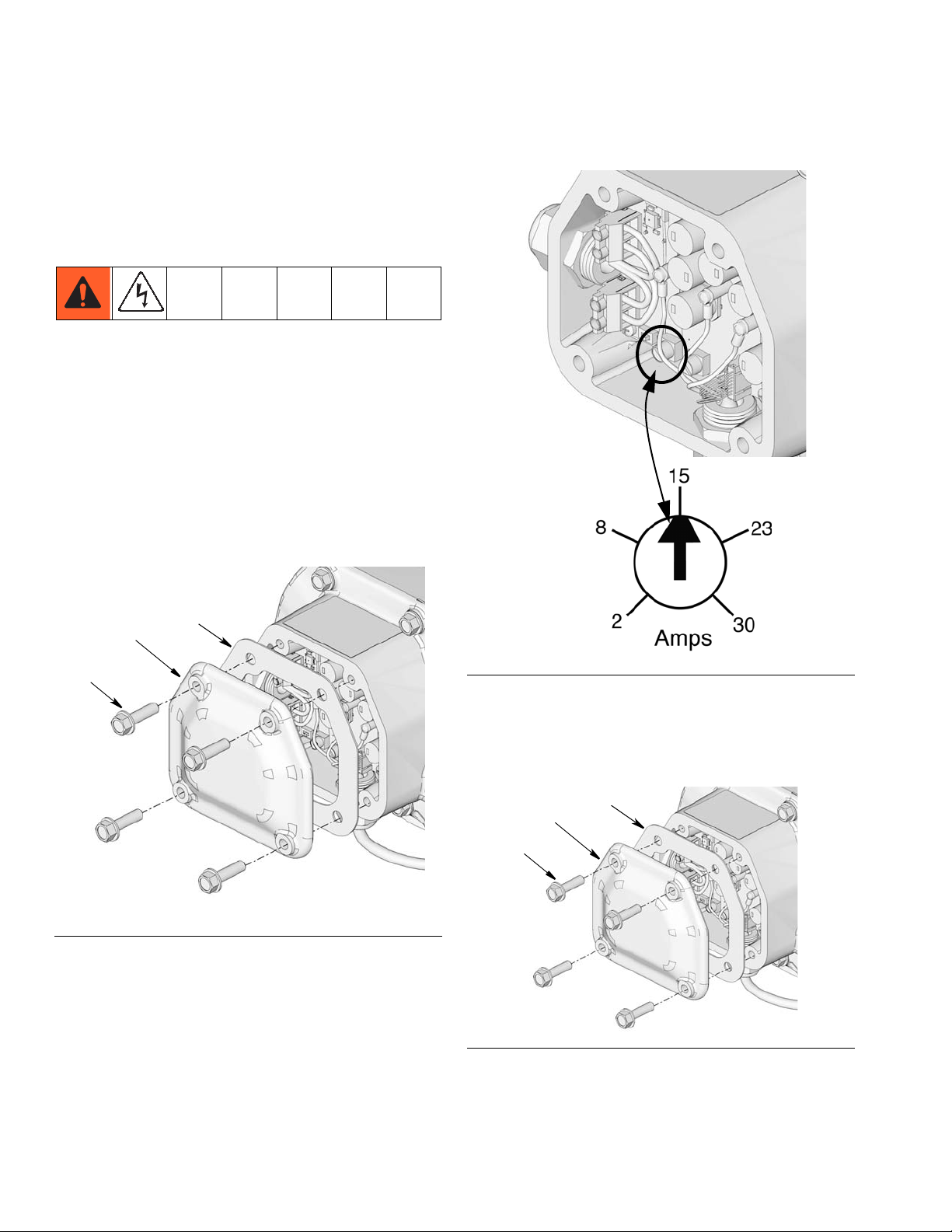
Dyna-Star Pump Current Control Adjustment
NOTE: The Dyna-Star Pump is designed to draw 40
Current Amps. The AC to DC conversion kit is only
designed for 20 Current Amps. The current control must
be adjusted on the Dyna-Star Motor Control Board for
20 Current Amps. The Dyna-Star pump will not run efficiently if this adjustment is not made.
1. Disconnect power to Dyna-Star pump.
2. On Dyna-Star pump, remove screws (116) from
motor control box cover (120) and remove cover
and gasket (119) (F
IG. 1).
value to the setting shown in F
IG. 2.
FIG. 1
3. Turn current control potentiometer knob
counter-clockwise to decrease the Amp setting
FIG. 2
4. Replace motor control board gasket (119) and cover
(120) with screws (116) (F
pinch any wires. Tighten bolts securely. Torque to
17 - 19 ft lbs (23 - 25 N.m).
FIG. 3
IG. 3) being careful not to
4 333391B
Page 5
Installation
12
1
c
12a
Enclosure Preparation
• Select a flat surface near the Dyna-Star pump to
install the Enclosure (1).
• Enclosure Mounting Dimensions are provided on
page 15 of this manual. They are provided for reference only and to use as a guide for pre-drilling
holes.
• 3 cord grips are included in the kit.
• 2 cord grips (12) are used for controller inter-
face and pressure switch.
• 1 cord grip (10) is used for power to the
Dyna-Star pump.
• Determine the location on the Enclosure box (1)
that best suits your application and add holes in
the box accordingly.
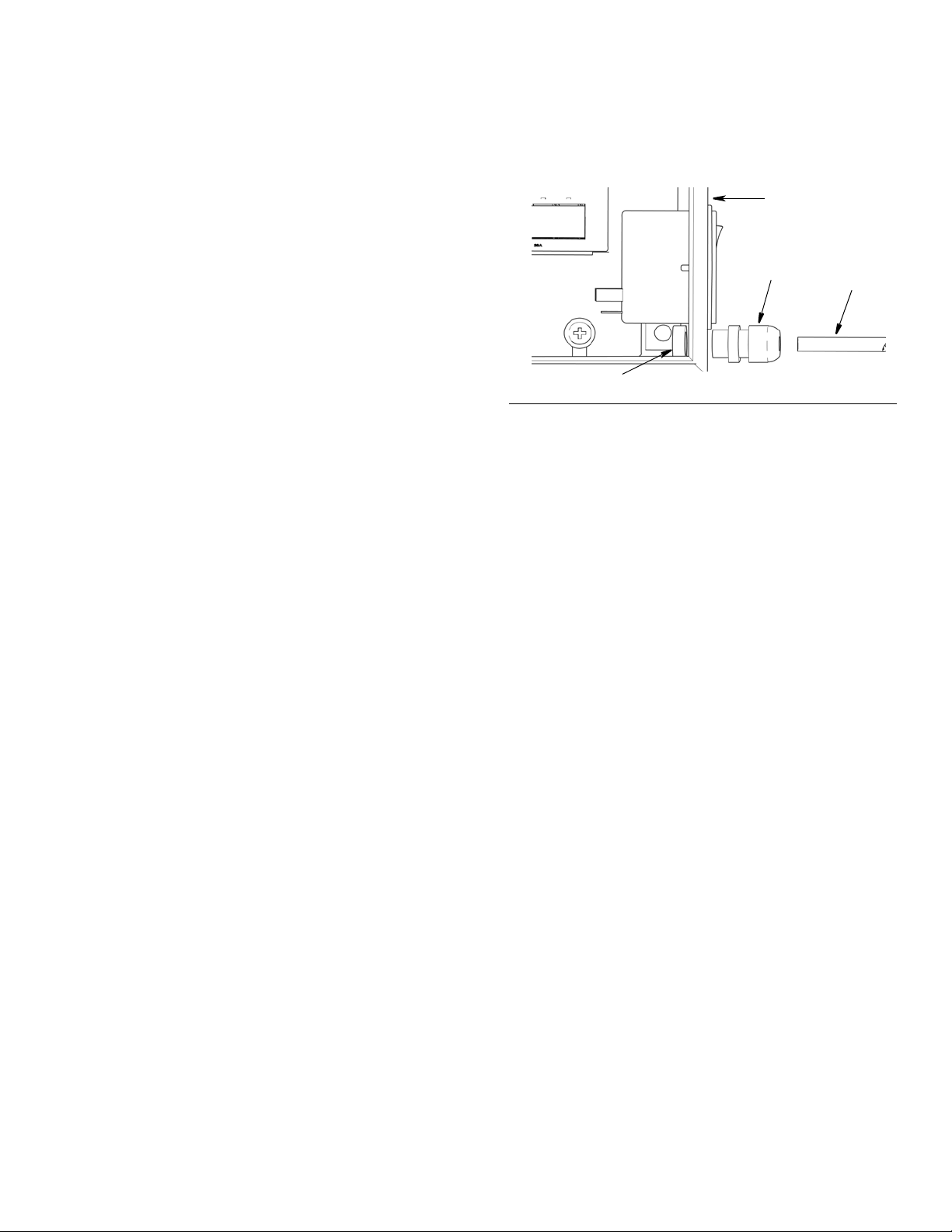
Controller Cord Grip Installation
• Cord Grip (12) (included in the kit) will accommodate a cable with an outside diameter of 0.230 in. -
0.395 in. (5.8 mm - 10.0 mm). If the outside diameter of your controller cord is not within this range, an
appropriately sized cord grip must be used.
Enclosure (1) as shown in F
sion nut and torque to 5.5 ft. lbs (7.5 N.m).
FIG. 4
IG. 4. Tighten compres-
Pressure Switch Cord Grip (Optional)
• Cord Grip (12) (included in the kit) will accommodate a cable with an outside diameter of 0.230 in. -
0.395 in. (5.8 mm - 10.0 mm). If the outside diameter of your pressure switch cord is not within this
range, an appropriately sized cord grip must be
used.
• Cord Grip (12) is used for installing the Pressure
Switch Wiring Harness in the Enclosure (1).
• Cord Grip (12) (included in kit) is used for installing
the GLC2200 Wiring Harness (24P314) in the
Enclosure (1).
• For your convenience and reference, Mounting
Dimensions are provided on page 16 of this manual.
Install the cord grip in a location that is the most efficient for your installation location.
1. Determine the best path for the wiring cable
between the controller and Enclosure (1).
2. Use a 3/4 inch (19 mm) drill bit to create the hole to
install Cord Grip (12) in the Enclosure (1).
NOTE: If a different sized cord grip is used an
appropriately sized drill bit must be used to create
the installation hole.
3. Deburr the hole to remove sharp edges.
4. Install cord grip through drilled hole in Enclosure (1).
Install lock nut on the inside of the Enclosure, over
threaded end of cord grip. Tighten nut securely to
hold cord grip in place. Torque nut to 5.9 ft. lbs (8
N.m).
5. Feed the end of the controller wiring harness (c)
through the cord grip and into the inside of the
• For your convenience and reference, Mounting
Dimensions are provided on page 16 of this manual.
Install the cord grip in a location that is the most efficient for your installation location.
1. Determine the best path for the wiring cable
between the Dyna-Star Pump and the Enclosure
(1).
2. Use a 3/4 inch (19 mm) drill bit to create the hole to
install Cord Grip (12) in the Enclosure (1).
NOTE: If a different sized cord grip is used an
appropriately sized drill bit must be used to create
the installation hole.
3. Deburr the hole to remove sharp edges.
4. Install cord grip through drilled hole in Enclosure (1).
Install lock nut on the inside of the Enclosure, over
threaded end of cord grip. Tighten nut securely to
hold cord grip in place. Torque nut to 5.9 ft. lbs (8
N.m).
5. Feed the wires through the cord grip and into the
inside of the Enclosure (1). Tighten compression nut
and torque to 5.5 ft. lbs (7.5 N.m).
333391B 5
Page 6
Installation
1
10
e
11
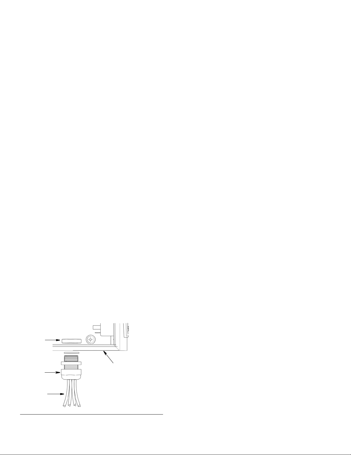
Electric Dyna-Star Cord Grip
• Cord Grip(10) (included in the kit) will accommodate
a cable with an outside diameter of 0.350 in. - 0.63
in. (9 mm - 16 mm). If the outside diameter of your
pump cable is not within this range, an appropriately
sized cord grip must be used.
• Cord Grip (10) included in kit) is used for installing
the Dyna-Star pump cord (77X528) in the Enclosure
(1).
• For your convenience and reference, Mounting
Dimensions are provided on page 16 of this manual.
Install the Cable Gland (10) in a location that is most
efficient for your installation location.
1. Determine the best path for the wiring cable
between the Dyna-Star Pump and the Enclosure
(1).
2. Use a 1 inch (25 mm) drill bit to create a hole to
install the Cable Gland Kit (10).
NOTE: If a different sized cord grip is used an
appropriately sized drill bit must be used to create
the installation hole.
3. Deburr the hole to remove sharp edges.
Controller Installation
NOTE:
• The following instructions are specifically written for
installing a Graco GLC2200 Controller. These
instructions may be modified or may be unnecessary if you are using a different type of controller or
a PLC with your system.
• For your convenience, Controller Mounting Dimensions for a Graco GLC2200 are provided on page
15 of this manual. They are provided for reference
only. Install the Controller in a location that is the
most efficient for your installation location.
GLC2200
Graco recommends installing the GLC2200 directly to
the side of the Enclosure (1). If that type of installation is
not feasible for your location, it can also be mounted
securely to a flat surface as close as possible to the
Enclosure (see Typical Installation option J, page 3).
NOTE: The GLC2200 wiring harness cord is 5 feet long.
• If the GLC2200 is installed to the side of the Enclosure (1) the wiring harness cord must be trimmed to
remove the excess length.
4. Install cable gland in drilled hole in Enclosure (1).
Install lock nut (11) on the inside of the enclosure,
over threaded end of cable gland. Tighten nut
securely to hold cable gland in place. Torque nut to
5.1 ft. lbs (7 N.m).
5. Feed the end of the pump wiring harness (e)
through the cable gland and into the inside of the
Enclosure (1) as shown in F
sion nut and torque to 3.7 ft. lbs (5 N.m).
FIG. 5
IG. 5. Tighten compres-
• If the GLC2200 is not mounted directly onto the side
of the Enclosure (1), be sure the mounting location
selected is close enough to the Enclosure to allow
sufficient cord length between the GLC2200 and the
connection points inside the Enclosure.
• Always pre-drill mounting holes in the Enclosure (1)
or your installation location.
Before drilling the mounting holes:
• Use the mounting hole dimensions provided in
the GLC2200 instruction manual as a guide to
pre-drill mounting holes
or,
• Mark the location of the two mounting holes by
positioning the GLC2200 Controller on the
installation location. Mark the location of each
mounting hole with a pencil.
6 333391B
Page 7

Installation
d
f
f
f
f
For GLC2200 Controller installations on the side of
the Enclosure (1):
NOTICE
To prevent damaging and/or contaminating the
GLC2200 Controller while pre-drilling the other holes in
the Enclosure (1), do not install the GLC2200 controller
to the side of the Enclosure until all mounting holes are
drilled.
GLC2200 Installation
1. Align the GLC2200 Controller with the pre-drilled
mounting holes on the Enclosure (1) or alternate
mounting surface.
2. Use two screws (not provided) to secure the
GLC2200 controller to the mounting surface.
NOTE: GLC220 installation on the Enclosure (1) is
shown in F
IG. 6.
Installing Enclosure to Mounting Surface
Install Enclosure (1) to mounting surface by aligning the
holes (f) in the enclosure box with the pre-drilled holes.
FIG. 6
3. Plug the large connector end (d) of the GLC2200
wiring harness into the GLC2200 as shown in F
6. The connector can only be plugged into the
GLC2200 one way. The clip should be facing to the
back (or down) when the connector is correctly oriented.
FIG. 7
Fuse Installation
NOTICE
Fuses are required. To avoid equipment damage:
• Never operate the Dyna-Star pump without a
fuse installed.
• A fuse of the correct voltage must be installed in
line with the power entry to the system.
A 6.3 Amp Fuse Kit, 16Y312 is available from Graco.
Discard unused fuses according to applicable local disposal guidelines
IG.
333391B 7
Page 8

Installation
f
17 or 18
g
1. Use a flat blade screwdriver to remove fuse box (f)
located under switch as shown in F
IG. 8.
FIG. 10
FIG. 8
2. Install 2 fuses (17 or 18) of the same amperage in
the fuse box.
NOTICE
To prevent breaking fuses during installation, do
not force the silver capped end of the fuse through
the fuse seat opening.
b. With the silver cap above the top of the fuse
box, gently push the glass tube into fuse seat as
shown in F
IG. 10.
c. Gently push down on the top silver fuse cap to
securely hold the fuse in the seat as shown in
F
IG. 11.
FIG. 11
3. Reinstall fuse box under switch (3).
FIG. 9
a. Insert the silver-capped end of fuse (17 or 18)
into bottom of fuse box (g) as shown in F
8 333391B
IG. 10.
Page 9

System Configuration and
16
7
16
6
h
j
Wiring
.
Improper installation may result in a risk of electric
shock. All electric wiring must be done by a qualified
electrician and comply with all local codes and regulations.
If the product is permanently connected, it must be connected to a grounded power source.
If an attachment plug is required in the end use
application:
• it must be rated for the product electrical specifications.
Installation
• it must be an approved, 3-wire grounding type
attachment plug.
• it must be plugged into an outlet that is properly
installed and grounded in accordance with all local
codes and ordinances.
Connecting Power Supply
1. To secure power supply to DIN rail, hook clips on
power supply (16) into DIN rail (7) (F
down firmly on lower edge of power supply until you
hear a click.
2. Gently pull up on the bottom edge of the power supply (16) to verify it is securely in place.
IG. 12). Push
FIG. 13
Dyna-Star Pump and Controller
Connections
1. Remove 2 to 3 inches of the outer insulation (h)
from bare end of the cable as shown F
.
FIG. 14
2. Strip each wire (j) as shown in FIG. 15.
IG. 14.
FIG. 15
FIG. 12
3. Connect wiring harness (6) (F
IG. 13) to AC input ter-
minals on power supply (16).
• Black wire - line (L)
• White wire - neutral (N)
• Green/yellow wire - ground / earth
333391B 9
Page 10

Installation
16
+ and -
bl
rd
rd
bl
26a
26
26a
3. Connect Red (+/rd) and Black (-/bl) wires from
Dyna-Star Cable and Controller Wiring Harness to
the corresponding + and - marked DC output terminals on the power supply (16) (see F
IG. 16).
FIG. 16
Controller Connections
NOTE: Use the LEVER-NUTS® (26) included in this kit
to make all controller wiring connections. Instructions for
using these LEVER-NUTS
ing section of this manual titled: LEVER-NUTS
®
are provided in the follow-
®
.
2. Push up lever (26a) on LEVER-NUTS
®
(26).
FIG. 18
3. Insert stripped end of wire into LEVER-NUTS® and
push down lever (26a).
GLC2200
Refer to the GLC2200 Lubrication Controller instruction
manual and GLC2200 Wiring Connector Kit instruction
manual wiring harness installation instructions.
User Supplied Controller
Refer to the Instruction Manual included with your Controller for instructions related to the wiring harness connections.
LEVER-NUTS
®
Use a LEVER-NUTS® (26) to connect wires.
1. Strip approximately 0.37 inches (9-10 mm) of insulation from the end of each wire.
FIG. 17
FIG. 19
®
4. Push LEVER-NUTS
and wires neatly inside enclosure, taking care to not crimp or pinch them when
enclosure door is closed.
NOTE: Depending on your application, all wires
included in the wiring harness may not be used. Blunt
cut the end of each unused wire and wrap it with electric
tape to prevent exposed wires from making contact with
any other wire.
FIG. 20
Installing Power Cord Clamp
1. Verify power to the system is disconnected and that
the power switch (3) is in the OFF position as shown
in F
IG. 21.
2. To determine the position to install the power cord
clamp (25) around the power cord, plug power cord
10 333391B
Page 11

plug (13) into the connector (3a) located below the
13
3
3a
b
25
24
25a
Outside of Enclosure
Inside of Enclosure
Wrench on Nut (23)
Wrench on Screw (24)
switch (3).
Installation
FIG. 23
FIG. 21
3. Position clamp around the cord near the plug and
mounting clamp installation hole (b).
NOTE: The clamp (25) should be installed close enough
to the power cord plug end to prevent the plug from
loosening itself from the connector (3a) when pulled;
resulting in an interruption or loss of power to the controller. See F
IG. 22.
6. Install nut (23) over end of screw (24) on the inside
of the Enclosure (1) (F
IG. 24). Use two wrenches
(one on the nut and one on the screw head) to
securely tighten nut and power cord clamp (25) to
the Enclosure (1).
FIG. 22
4. Unplug the power cord plug (13) from connector
(3a) (F
5. Insert screw (24) through the two silver tabs (25a)
on the cord clamp (F
through the installation hole in the enclosure.
333391B 11
IG. 22).
IG. 23). Then install screw
FIG. 24
Page 12

Installation
3
3a
13
Installing Power Cord
1. Verify power at the main power source is disconnected and that the correct amperage circuit
breaker for the input voltage is installed.
2. Hard wire or install a plug to the bare end of power
cord (13). Be sure to connect wires to the correct
polarity:
• Brown wire - line (L)
• Blue wire - neutral (N)
• Green/yellow wire - ground / earth
3. Verify power switch (3) is in the OFF position.
4. Plug power cord plug (13) into connector (3a)
located below switch (3).
5. Connect power at main power source.
6. Turn power switch to ON as shown in F
.
FIG. 25
IG. 25.
12 333391B
Page 13

Kit 77X524 Parts
8/9
19
1 BOX, enclosure 1
2 PANEL, enclosure, back 1
3 SWITCH, power, 120/240V 1
4 SCREW, mach, flh (not shown) 2
5 NUT, lock, hex (not shown) 2
6 HARNESS, filter, power supply (not
shown)
7 RAIL, mounting, DIN, 4 in. long 1
8 SCREW, grounding 1
9 NUT, keps, hex head 1
10 77X533 KIT, cable gland, includes 11 1
11 NUT, cable gland 1
12 121036 GRIP, cord, includes 12a 2
12a NUT, lock 2
13 CORD, power, IEC 1
14 186620 LABEL, ground symbol 1
15 SCREW, machine, pnh 2
16 POWER SUPPLY, 24 volt 1
18† 16Y312 FUSE, 6.3 AMP, 110 volt (not
shown)
19 196548 LABEL, warning, shock 1
21 WASHER, #8, plain flat 1
23 NUT, hex 1
24 SCREW, hex head 1
25 CLAMP 1
26
27 LABEL, instructions, power supply
LEVER-NUTS
(see Side View, page 16 for label
location)
®
(not shown)
Kit 77X524 Parts
Enclosure (1) PartsRef Part No. Description Qty
1
2
10
1
LEVER-NUTS® is a Registered Trademark of WAGO
Corporation.
Replacement Danger and Warning labels, tags, and
cards are available at no cost.
† Use fuses of the correct Amperage for your installation
location. Discard unused fuses according to applicable disposal regulations.
333391B 13
Page 14

Kit 77X524 Parts
7
1
2
15/21
16
13
3
12a
12
11
10
14
24
23
25
17/18
Ref A
Ref A
Kit 77X524 Inside Enclosure (1) Parts
14 333391B
Page 15

Technical Data
Dyna-Star HP and HF Pump AC to DC Conversion Kit
US Metric
Input Voltage 110-240V AC
Input Frequency 50/60 Hz
Output Voltage 24V DC
Output Current
IP Rating IP24
Environmental temperature range 14° to 122°F -10° to 50°C
Power Cord Length 9 feet 2.7 meters
Enclosure (1) Mounting Dimensions
20AMPS
Technical Data
333391B 15
Page 16

Technical Data
A
B
C
27
Cord Grip/Cable Gland Dimensions
Bottom View
Side View
Key:
A Electric Dyna-Star Cable
B Any other cable such as Pressure Switch
C GLC2200 Cable
16 333391B
Page 17

Notes
Notes
333391B 17
Page 18

Graco Standard Warranty
Graco warrants all equipment referenced in this document which is manufactured by Graco and bearing its name to be free from defects in
material and workmanship on the date of sale to the original purchaser for use. With the exception of any special, extended, or limited warranty
published by Graco, Graco will, for a period of twelve months from the date of sale, repair or replace any part of the equipment determined by
Graco to be defective. This warranty applies only when the equipment is installed, operated and maintained in accordance with Graco’s written
recommendations.
This warranty does not cover, and Graco shall not be liable for general wear and tear, or any malfunction, damage or wear caused by faulty
installation, misapplication, abrasion, corrosion, inadequate or improper maintenance, negligence, accident, tampering, or substitution of
non-Graco component parts. Nor shall Graco be liable for malfunction, damage or wear caused by the incompatibility of Graco equipment with
structures, accessories, equipment or materials not supplied by Graco, or the improper design, manufacture, installation, operation or
maintenance of structures, accessories, equipment or materials not supplied by Graco.
This warranty is conditioned upon the prepaid return of the equipment claimed to be defective to an authorized Graco distributor for verification of
the claimed defect. If the claimed defect is verified, Graco will repair or replace free of charge any defective parts. The equipment will be returned
to the original purchaser transportation prepaid. If inspection of the equipment does not disclose any defect in material or workmanship, repairs
will be made at a reasonable charge, which charges may include the costs of parts, labor, and transportation.
THIS WARRANTY IS EXCLUSIVE, AND IS IN LIEU OF ANY OTHER WARRANTIES, EXPRESS OR IMPLIED, INCLUDING BUT NOT
LIMITED TO WARRANTY OF MERCHANTABILITY OR WARRANTY OF FITNESS FOR A PARTICULAR PURPOSE.
Graco’s sole obligation and buyer’s sole remedy for any breach of warranty shall be as set forth above. The buyer agrees that no other remedy
(including, but not limited to, incidental or consequential damages for lost profits, lost sales, injury to person or property, or any other incidental or
consequential loss) shall be available. Any action for breach of warranty must be brought within two (2) years of the date of sale.
GRACO MAKES NO WARRANTY, AND DISCLAIMS ALL IMPLIED WARRANTIES OF MERCHANTABILITY AND FITNESS FOR A
PARTICULAR PURPOSE, IN CONNECTION WITH ACCESSORIES, EQUIPMENT, MATERIALS OR COMPONENTS SOLD BUT NOT
MANUFACTURED BY GRACO. These items sold, but not manufactured by Graco (such as electric motors, switches, hose, etc.), are subject to
the warranty, if any, of their manufacturer. Graco will provide purchaser with reasonable assistance in making any claim for breach of these
warranties.
In no event will Graco be liable for indirect, incidental, special or consequential damages resulting from Graco supplying equipment hereunder, or
the furnishing, performance, or use of any products or other goods sold hereto, whether due to a breach of contract, breach of warranty, the
negligence of Graco, or otherwise.
FOR GRACO CANADA CUSTOMERS
The Parties acknowledge that they have required that the present document, as well as all documents, notices and legal proceedings entered into,
given or instituted pursuant hereto or relating directly or indirectly hereto, be drawn up in English. Les parties reconnaissent avoir convenu que la
rédaction du présente document sera en Anglais, ainsi que tous documents, avis et procédures judiciaires exécutés, donnés ou intentés, à la suite
de ou en rapport, directement ou indirectement, avec les procédures concernées.
Graco Information
For the latest information about Graco products, visit www.graco.com.
For patent information, see www.graco.com/patents.
TO PLACE AN ORDER, contact your Graco distributor or call to identify the nearest distributor.
Phone: 612-623-6928 or Toll Free: 1-800-533-9655, Fax: 612-378-3590
All written and visual data contained in this document reflects the latest product information available at the time of publication.
GRACO INC. AND SUBSIDIARIES • P.O. BOX 1441 • MINNEAPOLIS MN 55440-1441 • USA
Copyright 2014, Graco Inc. All Graco manufacturing locations are registered to ISO 9001.
Graco reserves the right to make changes at any time without notice.
Original instructions. This manual contains English. MM 333391
Graco Headquarters: Minneapolis
International Offices: Belgium, China, Japan, Korea
www.graco.com
April 2014, revised June 2014
 Loading...