

Page 1
Instructions-Parts
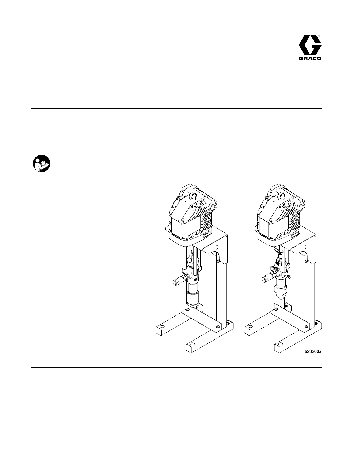
E-Flo®
E-Flo® E-Flo®
Electric
Electric Electric
For
For For
See Technical Data for Maximum
Working Pressure.
See page 3 for model part numbers and
approvals information.
drive
drive drive
professional
professional professional
Important
Important Important
Readallwarningsandinstructionsinthismanual.
Save
Save Save
DC
DC DC
piston
piston piston
use
use use
Safety
Safety Safety
these
instructions.
these these
instructions. instructions.
2–Ball
2–Ball 2–Ball
pumps
pumps pumps
only.
only. only.
for
for for
Instructions
Instructions Instructions
Piston
Piston Piston
low
to
low low
medium
to to
medium medium
volume
volume volume
Pumps
Pumps Pumps
paint
circulation
paint paint
circulation circulation
applications.
applications. applications.
EN
333389A
PROVENQUALITY.LEADINGTECHNOLOGY.
Page 2

Contents
Contents Contents
Models...............................................................3
RelatedManuals................................................3
Warnings...........................................................4
Installation..........................................................7
Location......................................................7
MountthePump..........................................7
PowerSupplyRequirements.........................7
ConnectthePowerSupply...........................10
Grounding...................................................11
FluidLineAccessories.................................12
FillWithOilBeforeUsingEquipment.............12
FlushBeforeUsingEquipment......................12
ControlModuleAccessory............................12
Operation...........................................................13
Startup........................................................13
Shutdown....................................................13
PressureReliefProcedure............................13
Maintenance......................................................14
PreventiveMaintenanceSchedule................14
ChangetheOil.............................................14
CheckOilLevel...........................................14
BearingPre-Load.........................................14
Wet-Cups....................................................14
Flushing......................................................14
Troubleshooting..................................................15
Repair................................................................16
Dura-FloLowers..........................................16
XtremeLowers............................................17
ReassembletheCouplingAdapterandTie
RodstotheMotor...........................19
Parts..................................................................20
XtremePumpAssembly...............................20
Dura-FloPumpAssembly.............................22
PumpMatrix................................................24
Dimensions........................................................26
MountingHolePatterns.......................................27
StandMount................................................27
WallMount..................................................28
PerformanceCharts............................................29
TechnicalData...................................................32
Notes................................................................33
GracoStandardWarranty....................................34
2
333389A
Page 3
Models
Models Models
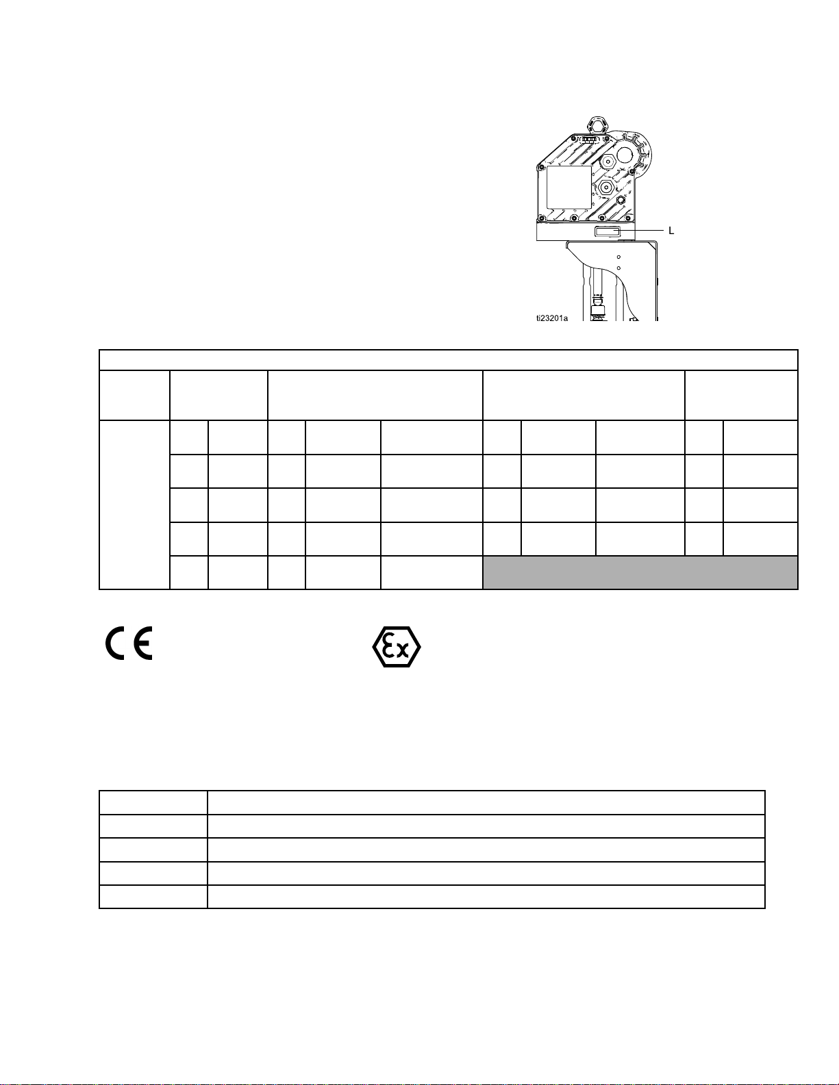
Thesixdigitpartnumberforyourequipmentis
printedontheequipmentidenticationlabel(L).
Refertothetablebelowforinformationregardingthe
congurationofyourequipment.
SeePumpMatrix,page24
,foracompletelistof
pumppartnumbers.
Flo
DC
Pump
Part
E EE- --Flo Flo
DC DC
Pump Pump
First
and
First First
and and
Second
Second Second
Digit
Digit Digit
ES
Third
Third Third
Digit
Digit Digit
7145CC3BasicATEX/FM/
8180CC4AdvancedATEX/FM/
9220CC7BasicATEX/IECEx/
0290CC8AdvancedATEX/IECEx/
Number
Part Part
Number Number
Digit
Digit Digit
Lower
Lower Lower
Size
Size Size
Conguration
Conguration Conguration
Fourth
Fourth Fourth
Digit
Digit Digit
Motor
Motor Motor
Control
Control Control
Models
Digit
Digit Digit
Approvals
Approvals Approvals
IECEx
IECEx
TIIS/KCS
TIIS/KCS
Digit
Digit Digit
4Carbon
5Stainless
6Stainless
Fifth
Digit
Fifth Fifth
Digit Digit
Pump
Pump Pump
Material
Material Material
Steel
Steel
Steel
Packings
Packings Packings
3Xtreme
2Leather
4Leather
1PTFE
PTFE
Leather
Digit
Digit Digit
Sixth
Sixth Sixth
0None
1Stand
2Wall
Digit
Digit Digit
Mounting
Mounting Mounting
Type
Type Type
IIA
II IIII2 22G GGc ccIIA IIA
NOTE:
NOTE: NOTE:
Related
Related Related
SeetheE-FloDCMotormanualformotorapprovalsinformation.
Manuals
Manuals Manuals
Manual
Manual Manual
3A2526
3A2527
No.
No. No.
Description
Description Description
Instructions-PartsManual,E-FloDCMotor
Instructions-PartsManual,forE-FloDCControlModuleKit
T3
T3 T3
311762Instructions-PartsManual,XtremeLowers
311827Instructions-PartsManual,Dura-FloLowers
333389A 3
Page 4
Warnings
Warnings
Warnings Warnings
Thefollowingwarningsareforthesetup,use,grounding,maintenance,andrepairofthisequipment.The
exclamationpointsymbolalertsyoutoageneralwarningandthehazardsymbolsrefertoprocedure-specic
risks.Whenthesesymbolsappearinthebodyofthismanual,referbacktotheseWarnings.Product-specic
hazardsymbolsandwarningsnotcoveredinthissectionmayappearthroughoutthebodyofthismanual
whereapplicable.
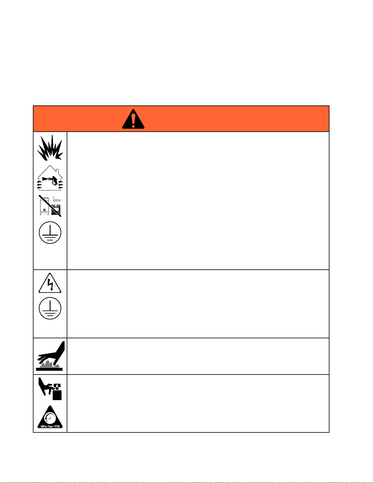
WARNING
WARNING WARNING
FIRE
AND
FIRE FIRE
Flammablefumes,suchassolventandpaintfumes,inwork work
preventreandexplosion:
•Useequipmentonlyinwellventilatedarea.
•Eliminateallignitionsources;suchaspilotlights,cigarettes,portableelectriclamps,and
plasticdropcloths(potentialstaticarc).
•Keepworkareafreeofdebris,includingsolvent,ragsandgasoline.
•Donotplugorunplugpowercords,orturnpowerorlightswitchesonoroffwhenammable
fumesarepresent.
•Groundallequipmentintheworkarea.SeeGrounding Grounding
•Useonlygroundedhoses.
•Holdgunrmlytosideofgroundedpailwhentriggeringintopail.Donotusepaillinersunless
theyareantistaticorconductive.
Stop
•Stop Stop
equipmentuntilyouidentifyandcorrecttheproblem.
•Keepaworkingreextinguisherintheworkarea.
ELECTRIC
ELECTRIC ELECTRIC
Thisequipmentmustbegrounded.Impropergrounding,setup,orusageofthesystemcan
causeelectricshock.
EXPLOSION
AND AND
EXPLOSION EXPLOSION
operation
operation operation
immediately
immediately immediately
SHOCK
SHOCK SHOCK
HAZARD
HAZARD HAZARD
work
area
area area
canigniteorexplode.Tohelp
Grounding
ifstaticsparkingoccursoryoufeelashock,Donotuse
HAZARD
HAZARD HAZARD
instructions.
•Turnoffanddisconnectpoweratmainswitchbeforedisconnectinganycablesandbefore
servicingorinstallingequipment.
•Connectonlytogroundedpowersource.
•Allelectricalwiringmustbedonebyaqualiedelectricianandcomplywithalllocalcodes
andregulations.
BURN
BURN BURN
Equipmentsurfacesanduidthat’sheatedcanbecomeveryhotduringoperation.Toavoid
severeburns:
•Donottouchhotuidorequipment.
MOVING
MOVING MOVING
Movingpartscanpinch,cutoramputatengersandotherbodyparts.
•Keepclearofmovingparts.
•Donotoperateequipmentwithprotectiveguardsorcoversremoved.
•Pressurizedequipmentcanstartwithoutwarning.Beforechecking,moving,orservicing
4
HAZARD
HAZARD HAZARD
PARTS
PARTS PARTS
equipment,followthePressure Pressure
HAZARD
HAZARD HAZARD
Pressure
Relief
Procedure
Relief Relief
Procedure Procedure
anddisconnectallpowersources.
333389A
Page 5
WARNING
WARNING WARNING
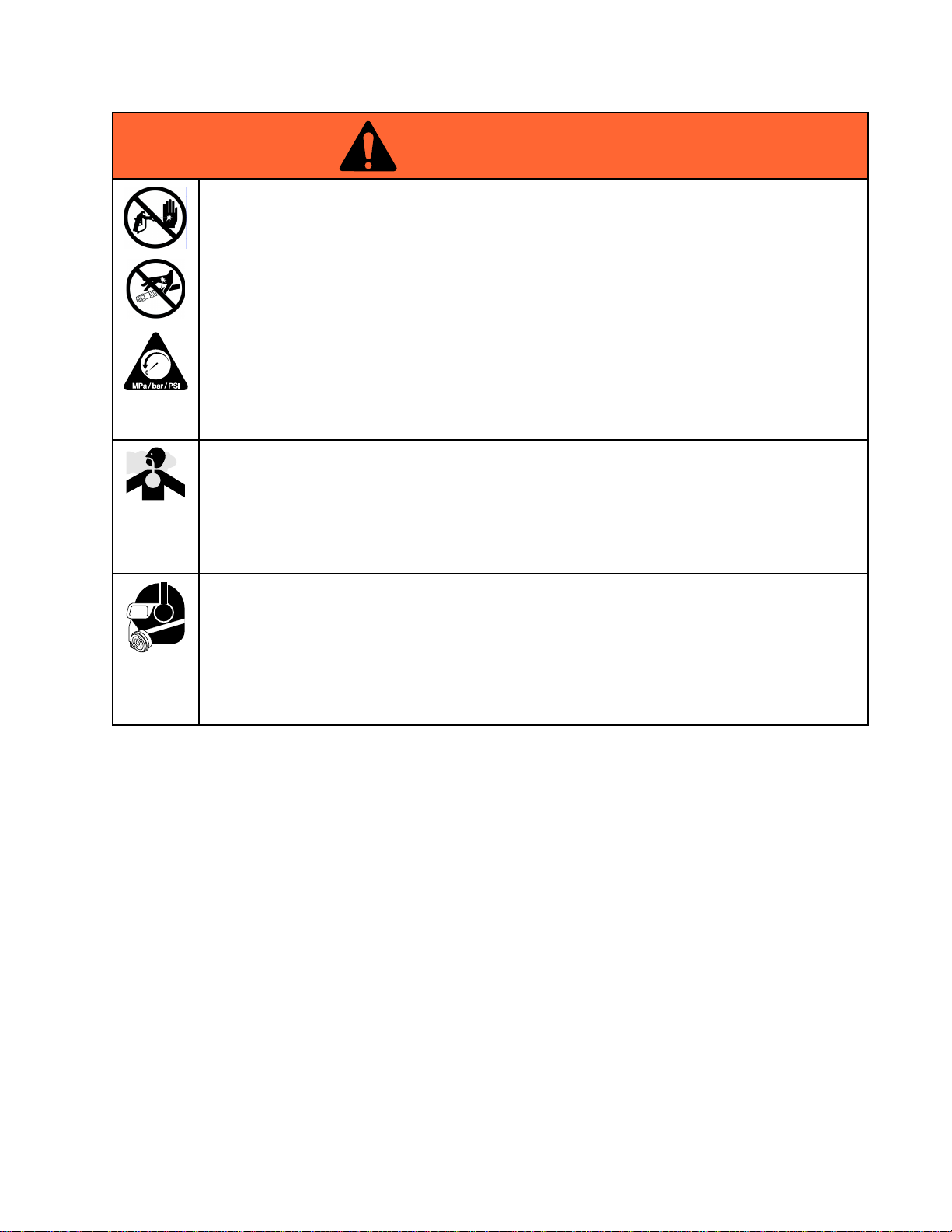
SKIN
INJECTION
SKIN SKIN
INJECTION INJECTION
High-pressureuidfromdispensingdevice,hoseleaks,orrupturedcomponentswillpierce
skin.Thismaylooklikejustacut,butitisaseriousinjurythatcanresultinamputation.Get Get
immediate
immediate immediate
•Engagetriggerlockwhennotdispensing.
•Donotpointdispensingdeviceatanyoneoratanypartofthebody.
•Donotputyourhandovertheuidoutlet.
•Donotstopordeectleakswithyourhand,body,glove,orrag.
•FollowthePressure Pressure
checking,orservicingequipment.
•Tightenalluidconnectionsbeforeoperatingtheequipment.
•Checkhosesandcouplingsdaily.Replacewornordamagedpartsimmediately.
TOXIC
TOXIC TOXIC
Toxicuidsorfumescancauseseriousinjuryordeathifsplashedintheeyesoronskin,
inhaled,orswallowed.
•ReadMSDSstoknowthespecichazardsoftheuidsyouareusing.
•Storehazardousuidinapprovedcontainers,anddisposeofitaccordingtoapplicable
guidelines.
PERSONAL
PERSONAL PERSONAL
Wearappropriateprotectiveequipmentwhenintheworkareatohelppreventseriousinjury,
includingeyeinjury,hearingloss,inhalationoftoxicfumes,andburns.Thisequipmentincludes
butisnotlimitedto:
surgical
surgical surgical
FLUID
FLUID FLUID
HAZARD
HAZARD HAZARD
treatment.
treatment. treatment.
Pressure
OR
OR OR
PROTECTIVE
PROTECTIVE PROTECTIVE
Relief
Procedure
Relief Relief
Procedure Procedure
FUMES
FUMES FUMES
EQUIPMENT
EQUIPMENT EQUIPMENT
whenyoustopdispensingandbeforecleaning,
Warnings
Get
•Protectiveeyewear,andhearingprotection.
•Respirators,protectiveclothing,andglovesasrecommendedbytheuidandsolvent
manufacturer.
333389A 5
Page 6
Warnings
WARNING
WARNING WARNING
EQUIPMENT
EQUIPMENT EQUIPMENT
Misusecancausedeathorseriousinjury.
•Donotoperatetheunitwhenfatiguedorundertheinuenceofdrugsoralcohol.
•Donotexceedthemaximumworkingpressureortemperatureratingofthelowestrated
systemcomponent.SeeTechnical Technical
•Useuidsandsolventsthatarecompatiblewithequipmentwettedparts.SeeTechnical Technical
inallequipmentmanuals.Readuidandsolventmanufacturer’swarnings.Forcomplete
informationaboutyourmaterial,requestMSDSfromdistributororretailer.
•Donotleavetheworkareawhileequipmentisenergizedorunderpressure.
•TurnoffallequipmentandfollowthePressure Pressure
•Checkequipmentdaily.Repairorreplacewornordamagedpartsimmediatelywithgenuine
manufacturer’sreplacementpartsonly.
•Donotalterormodifyequipment.Alterationsormodicationsmayvoidagencyapprovals
andcreatesafetyhazards.
•Makesureallequipmentisratedandapprovedfortheenvironmentinwhichyouareusingit.
•Useequipmentonlyforitsintendedpurpose.Callyourdistributorforinformation.
•Routehosesandcablesawayfromtrafcareas,sharpedges,movingparts,andhotsurfaces.
•Donotkinkoroverbendhosesorusehosestopullequipment.
•Keepchildrenandanimalsawayfromworkarea.
•Complywithallapplicablesafetyregulations.
MISUSE
MISUSE MISUSE
HAZARD
HAZARD HAZARD
Technical
Data
Data Data
Pressure
inallequipmentmanuals.
Relief
Relief Relief
Technical
Procedure
Procedure Procedure
whenequipmentisnotinuse.
Data
Data Data
6 333389A
Page 7
Installation
Installation
Installation Installation
Wall
Mount
Wall Wall
Mount Mount
SeeWallMountingHolePattern,page28.
Installationofthisequipmentinvolvespotentially
hazardousprocedures.Onlytrainedandqualied
personnelwhohavereadandwhounderstand
theinformationinthismanualshouldinstallthis
equipment.
Location
Location Location
Whenselectingthelocationfortheequipment,keep
thefollowinginmind:
•Theremustbesufcientspaceonallsidesof
theequipmentforinstallation,operatoraccess,
maintenance,andaircirculation.
•Ensurethatthemountingsurfaceandmounting
hardwarearestrongenoughtosupporttheweight
oftheequipment,uid,hoses,andstresscaused
duringoperation.
•Theremustbeastart/stopcontrol(C)
withineasyreachoftheequipment.See
TypicalInstallation,page9
Mount
Mount Mount
Stand
Stand Stand
SeeStandMountingHolePattern,page27
the
Pump
the the
Pump Pump
Mount
Mount Mount
.
1.Selectasolidpositiononawallforthemounting
bracket.Thewallshouldbecapableofsupporting
thepumpandaccessoriesthatwillbeattached
tothebracket,anyadditionalweightoftheuid
usedinthepump,andanystressorstrainthat
maybeappliedduringpumpoperation.
2.Drillfour7/16in.(11mm)diameterholesforthe
mountingbolts,approximately5ft(1.5m)above
theoor,usingthewallbracketasatemplate.
Useanyofthethreemountingholegroupings
3.Boltthebracketsecurelytothewall.Usebolts
designedtoholdinthewall’sconstruction.
4.Placethepumpandaccessoriesoverthe
bracket’smountingholesandsecurewithscrews
(5)andwashers(4)supplied.
Power
Power Power
Improperwiringmaycauseelectricshockorother
seriousinjuryifworkisnotperformedproperly.
Haveaqualiedelectricianperformanyelectrical
work.Besureyourinstallationcomplieswithall
National,StateandLocalsafetyandrecodes.
Supply
Supply Supply
Requirements
Requirements Requirements
1.Selectalevelsurfaceforthestandtobemounted
to.
2.SecurethestandtotheoorwithM19(5/8in.)
bolts.Useboltsthatengageatleast152mm
(6in.)intotheoortopreventthepumpfrom
tipping.
3.Placethepumpandaccessoriesoverthe
bracket’smountingholesandsecurewithbolts
(5)andwashers(4)supplied.
4.Useshimstolevelthepumpasrequired.
333389A
Thesystemrequiresadedicatedcircuitprotected
withacircuitbreaker.Seetablebelowforpower
supplyrequirements.
Table
Table Table
Model
Model Model
EM0021
EM0022
Power
1 11. ..Power Power
Supply
Supply Supply
Voltage
Voltage Voltage
200–250
Vac
Specications
Specications Specications
Phase
Phase Phase
150/6020A
Hz
Hz Hz
Current
Current Current
7
Page 8

Installation
Hazardous
Hazardous Hazardous
Requirements
Requirements Requirements
Explosion
Explosion Explosion
Allelectricalwiringinthehazardousareamustbe
encasedinClassI,DivisionI,GroupDapproved
explosion-proofconduit.FollowallNational,State,
andLocalelectriccodes.
Aconduitseal(D)isrequiredwithin18in.(457mm)
ofthemotorfortheUSandCanada.SeeFig.3.
Allcablesmustberatedat70°C(158°F).
Area
Cabling
Area Area
Cabling Cabling
Proof
Proof Proof
and
Conduit
and and
Conduit Conduit
Flame
Flame Flame
Useappropriateconduit,connectors,andcable
glandsratedforATEXII2G.FollowallNational,
State,andLocalelectriccodes.
Allcableglandsandcablesmustberatedat70°C
(158°F).
Proof
Proof Proof
(ATEX)
(ATEX) (ATEX)
8 333389A
Page 9
Installation
Typical
Typical Typical
Installation
Installation Installation
NON
HAZARDOUS
NON NON
- --HAZARDOUS HAZARDOUS
AREA
AREA AREA
HAZARDOUS
HAZARDOUS HAZARDOUS
AREA
AREA AREA
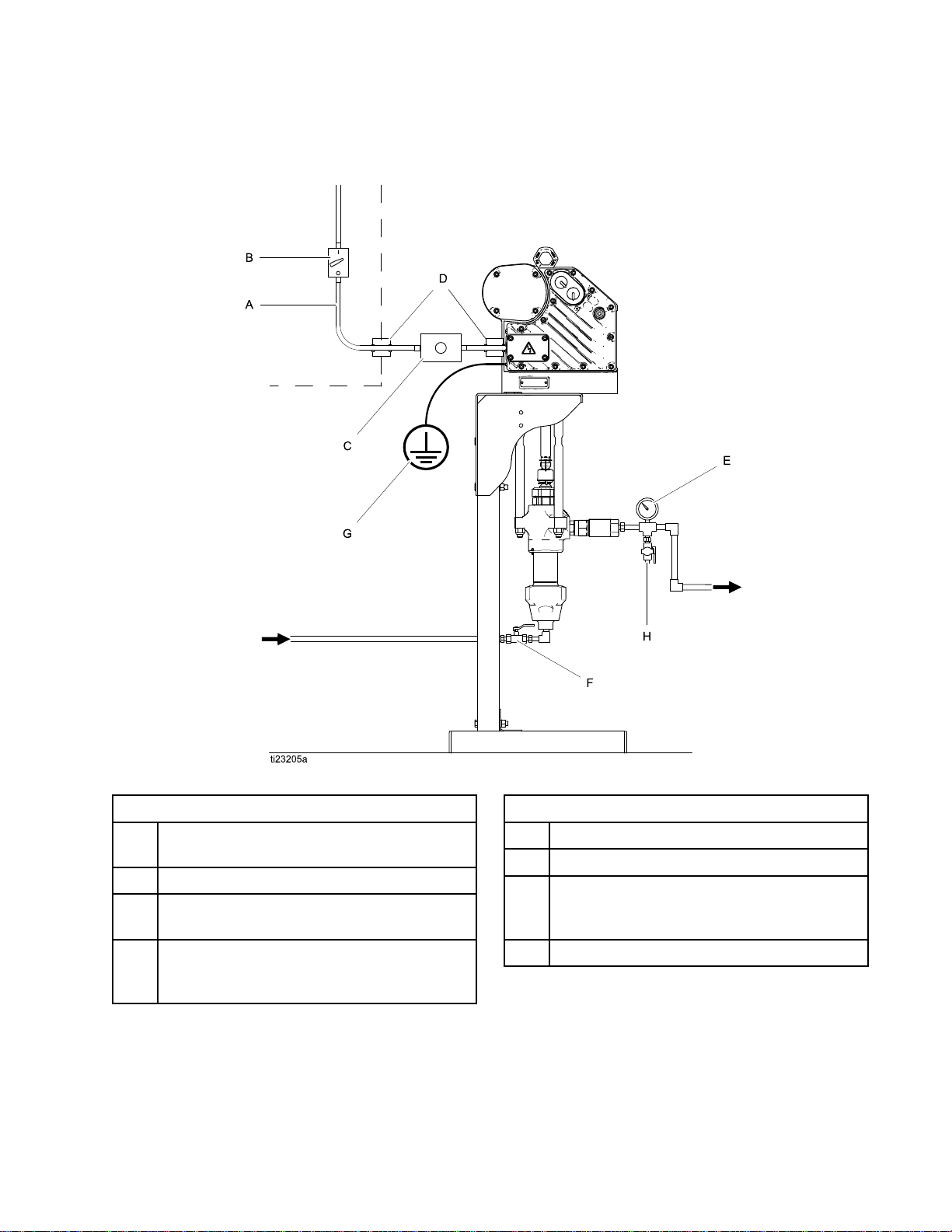
Figure1TypicalInstallation
Key
for
Fig.
Key Key
for for
A
B
CStart/StopControl(mustbeapprovedfor
D
1
Fig. Fig.
1 1
ElectricalSupply(mustbesealedconduit
approvedforuseinhazardouslocations)
FusedSafetySwitch,withlock
useinhazardouslocations)
ExplosionProofConduitSeal.Required
within18in.(457mm)ofthemotorforthe
USandCanada.
Key
for
Fig.
Key Key
for for
E
F
GPumpGroundWire.Twogroundterminals
HFluidDrainValve
1
Fig. Fig.
1 1
FluidPressureGauge
FluidShutoffValve
areprovidediflocalcoderequiresredundant
groundingconnections.
333389A 9
Page 10
Installation
Connect
Connect Connect
Improperwiringmaycauseelectricshockorother
seriousinjuryifworkisnotperformedproperly.
Haveaqualiedelectricianperformanyelectrical
work.Besureyourinstallationcomplieswithall
localcodesandregulations.
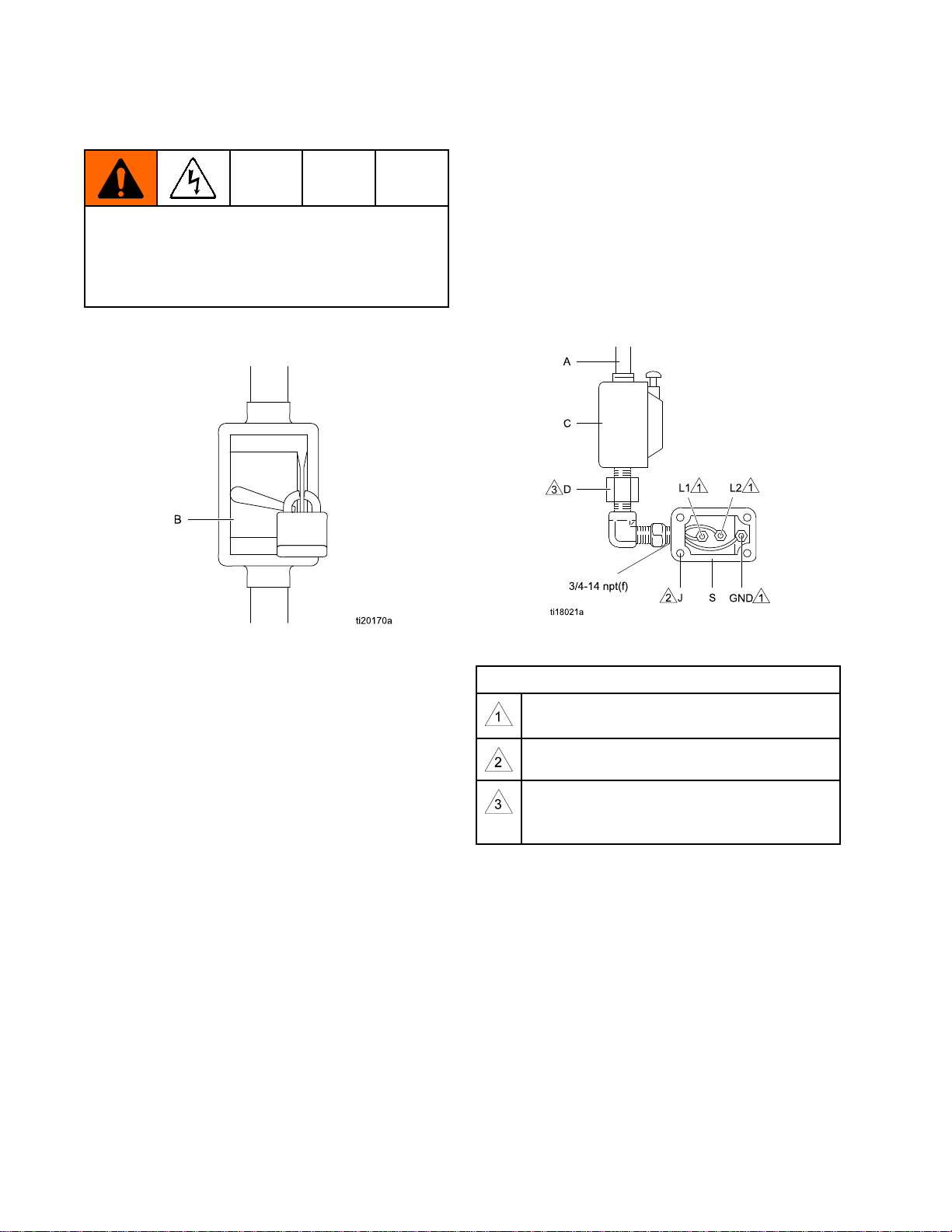
1.Ensurethatthefusedsafetyswitch(B,Fig2)is
shutoffandlockedout.
the
Power
the the
Power Power
Supply
Supply Supply
3.Opentheelectricalcompartment(S)onthe
motor.
4.Bringthepowerwiresintotheelectrical
compartmentthroughthe3/4–14npt(f)inletport.
Connectthewirestotheterminals,asshown.
Torquetheterminalnutsto25in-lb(2.8N•m)
Do
not
maximum.Do Do
5.Closetheelectricalcompartment.Torquethe
coverscrewsto15ft-lb(20.3N•m).
over-torque.
not not
over-torque. over-torque.
Figure2LockedOutFusedSafetySwitch
2.SeeFig.3.Installastart/stopcontrol(C)inthe
electricalsupplyline(A),withineasyreachof
theequipment.Thestart/stopcontrolmustbe
approvedforuseinhazardouslocations.
Figure3ConnectthePowerWires
Notes
for
Fig.
Notes Notes
for for
Tightenallterminalnutsto25in-lb(2.8N•m)
maximum.Do Do
Tightencoverscrewsto15ft-lb(20.3N•m).
Aconduitseal(D)isrequiredwithin18
in.(457mm)ofthemotorfortheUSand
Canada.
3
Fig. Fig.
3 3
Do
not
over
not not
torque.
over over
- --torque. torque.
10 333389A
Page 11

Grounding
Grounding Grounding
Thisequipmentmustbegroundedtoreducethe
riskofstaticsparkingandelectricshock.Electric
orstaticsparkingcancausefumestoigniteor
explode.Impropergroundingcancauseelectric
shock.Groundingprovidesanescapewireforthe
electriccurrent.
Pump:
1.Pump: Pump:
attachagroundwire.Tightenthegroundscrew
securely.Connecttheotherendoftheground
wiretoatrueearthground.
NOTE:
NOTE: NOTE:
ofthe24P822ControlModule.Allpumps
connectedtoacommoncontrolmodulemustbe
groundedtothesamegroundpoint.Different
groundpoints(unequalpotential)maycause
currenttoowthroughcomponentcables,
causingincorrectsignals.
SeeFig.4.Loosenthegroundscrewand
Advancedmodelsrequireinstallation
Figure4GroundWire
Fluid
2.Fluid Fluid
3.Fluid Fluid
hoses:
hoses: hoses:
hoseswithamaximumof500ft.(150m)
combinedhoselengthtoensuregrounding
continuity.Checktheelectricalresistanceof
hoses.Iftotalresistancetogroundexceeds25
megohms,replacehoseimmediately
Fluid
supply
supply supply
Useonlyelectricallyconductive
container:
container: container:
Followyourlocalcode.
Installation
333389A
11
Page 12

Installation
Fluid
Fluid Fluid
InstallthefollowingaccessoriesasshowninFig.
1,usingadaptersasnecessary.Alluidlinesand
accessoriesmustberatedtothemaximumworking
pressureof400psi(2.8MPa,28.0bar).
•Fluid Fluid
•Fluid Fluid
•Fluid Fluid
Fill
Fill Fill
SeeFig.5.Beforeusingtheequipment,openthell
cap(P)andaddGracoPartNo.16W645ISO220
silicone-freesyntheticgearoil.Checktheoillevelin
thesightglass(K).Filluntiltheoillevelisnearthe
halfwaypointofthesightglass.Theoilcapacityis
approximately1.5quarts(1.4liters).Do Do
NOTE:
NOTE: NOTE:
suppliedwiththeequipment.
Line
Line Line
Fluid
drain
drain drain
relieveuidpressureinthehoseandcirculation
system.
Fluid
pressure
pressure pressure
adjustmentoftheuidpressure.
Fluid
shutoff
shutoff shutoff
With
With With
Two1quart(0.95liter)bottlesofoilare
Accessories
Accessories Accessories
valve
(H):
valve valve
(H): (H):
requiredinyoursystem,to
gauge
gauge gauge
valve
valve valve
Oil
Before
Oil Oil
Before Before
(F):
(F): (F):
(E):
(E): (E):
shutsoffuidow.
Using
Using Using
formoreprecise
Equipment
Equipment Equipment
Do
not
overll.
not not
overll. overll.
Figure5SightglassandOilFillCap
Flush
Flush Flush
Thepumpuidsectionwastestedwithlightweight
oil,whichisleftintheuidpassagestoprotectparts.
Toavoidcontaminatingyouruidwithoil,ushthe
equipmentwithacompatiblesolventbeforeusing
theequipment.
Before
Before Before
Using
Using Using
Equipment
Equipment Equipment
Control
Control Control
TheControlModuleAccessoryisrequiredwith
AdvancedE-FloDCmotorstoprovidetheinterface
foruserstoenterselectionsandviewinformation
relatedtosetupandoperation.SeetheControl
ModuleAccessoryKitmanualforinstallationand
operationinformation.
Module
Module Module
Accessory
Accessory Accessory
12
333389A
Page 13

Operation
Operation
Operation Operation
Startup
Startup Startup
Tooperatethepump,followtheStartupinstructions
fortheBasicorAdvancedmotorintheMotormanual.
TheAdvancedE-FloDCmotorsrequireinstallationof
the24P822ControlModuleAccessoryKittoprovide
theinterfaceforuserstoenterselectionsandview
informationrelatedtosetupandoperation.Seethe
ControlModuleAccessoryKitmanualforinstallation
andoperationinformation.
Runthepumpataslowspeeduntiltheuidlinesare
primedandallairisforcedoutofthesystem.
NOTE:
NOTE: NOTE:
waterbornepaints.
Shutdown
Shutdown Shutdown
FollowthePressureReliefProcedure,page13.Stop
thepumpatthebottomofitsstroketopreventuid
fromdryingontheexposeddisplacementrodand
damagingthethroatpackings.
Xtremepumpsshouldnotbeusedfor
Pressure
Pressure Pressure
Thisequipmentstayspressurizeduntilpressureis
manuallyrelieved.Tohelppreventseriousinjury
fromsplashinguidandmovingparts,followthe
PressureReliefProcedurewhenyoustopspraying
andbeforecleaning,checking,orservicingthe
equipment.
1.Disengagethestart/stopcontrol(C).SeeFig.1.
2.Shutoffandlockoutthefusedsafetyswitch(B).
3.Opentheuiddrainvalve(H),havingawaste
containerreadytocatchdrainage.Leaveopen
untilyouarereadytopressurizesystemagain.
Relief
Relief Relief
Procedure
Procedure Procedure
333389A 13
Page 14

Maintenance
Maintenance
Maintenance Maintenance
Preventive
Preventive Preventive
Theoperatingconditionsofyourparticularsystem
determinehowoftenmaintenanceisrequired.
Establishapreventivemaintenancescheduleby
recordingwhenandwhatkindofmaintenanceis
needed,andthendeterminearegularschedulefor
checkingyoursystem.
Change
Change Change
NOTE:
NOTE: NOTE:
200,000–300,000cycles.Afterthebreak-inperiod,
changetheoilonceayear.
1.SeeFig.6.Placeaminimum2quart(1.9liter)
2.Reinstalltheoildrainplug(25).Torqueto25–30
3.SeeFig.7.Openthellcap(P)andaddGraco
4.Reinstallthellcap.
Changetheoilafterabreak-inperiodof
containerundertheoildrainport.Removethe
oildrainplug(25).Allowalloiltodrainfromthe
motor.
ft-lb(34–40N•m).
PartNo.16W645ISO220silicone-freesynthetic
gearoil.Checktheoillevelinthesightglass(K).
Filluntiltheoillevelisnearthehalfwaypointof
thesightglass.Theoilcapacityisapproximately
1.5quarts(1.4liters).Do Do
Maintenance
Maintenance Maintenance
the
Oil
the the
Oil Oil
Do
Schedule
Schedule Schedule
not
overll.
not not
overll. overll.
Check
Check Check
SeeFig.7.Checktheoillevelinthesightglass(K).
Theoillevelshouldbenearthehalfwaypointofthe
sightglasswhentheunitisnotrunning.Iflow,open
thellcap(P)andaddGracoPartNo.16W645ISO
220silicone-freesyntheticgearoilasrequired.The
oilcapacityisapproximately1.5quarts(1.4liters).
Do
Do Do
Figure7SightglassandOilFillCap
Bearing
Bearing Bearing
SeeFig.7.Thebearingpre-loads(R)arefactory
setandarenotuseradjustable.Donotadjustthe
bearingpre-loads.
Oil
Level
Oil Oil
Level Level
not
overll.
not not
overll. overll.
Pre
Load
Pre Pre
- --Load Load
Figure6OilDrainPlug
14
Wet
Cups
Wet Wet
- --Cups Cups
Checkthewet-cupdaily.Keepthewet-cup1/3lled
withGracoThroatSealLiquid(TSL™)orcompatible
solvent.
Flushing
Flushing Flushing
•Flushbeforechanginguids,beforeuidcandry
intheequipment,attheendoftheday,before
storing,andbeforerepairingequipment.
•Flushatthelowestpressurepossible.Check
connectorsforleaksandtightenasnecessary.
•Flushwithauidthatiscompatiblewiththeuid
beingdispensedandtheequipmentwettedparts.
333389A
Page 15

Troubleshooting
Troubleshooting
Troubleshooting Troubleshooting
NOTE:
NOTE: NOTE:
Checkallpossibleremediesbeforedisassemblingthepump.
NOTE:
NOTE: NOTE:
manualforfurtherinformation.
TheLEDonthemotorwillblinkifanerrorisdetected.SeeError Error
Problem
Problem Problem
Pumpoutputlowonbothstrokes.
Pumpoutputlowononlyone
stroke.
Nooutput.Improperlyinstalledballcheck
Pumpoperateserratically.
Pumpwillnotoperate.
Cause
Cause Cause
Inadequatepowersupply.
Exhausteduidsupply.Rellandreprimepump.
Cloggeduidoutletline,valves,
etc.
Wornpistonpacking.
Heldopenorwornballcheck
valves.
Wornpistonpacking.
valves.
Exhausteduidsupply.Rellandreprimepump.
Heldopenorwornballcheck
valves.
Wornpistonpacking.
Inadequatepowersupply.
Error
Code
Troubleshooting
Code Code
Troubleshooting Troubleshooting
Solution
Solution Solution
SeePowerSupplyRequirements,
page7
Clear.
Replace.Seelowermanual.
Checkandrepair.Seelower
manual.
Replace.Seelowermanual.
Checkandrepair.Seelower
manual.
Checkandrepair.Seelower
manual.
Replace.Seelowermanual.
SeePowerSupplyRequirements,
page7.
.
inthemotor
Exhausteduidsupply.Rellandreprimepump.
Cloggeduidoutletline,valves,
etc.
Fluiddriedonpistonrod.Disassembleandcleanpump.
Clear.
Seelowermanual.Infuture,stop
pumpatbottomofstroke.
333389A 15
Page 16

Repair
Repair
Repair Repair
Dura
Dura Dura
Disassembly
Disassembly Disassembly
1.Stopthepumpatthebottomofitsstroke.
2.Relievethepressure.See
3.Disconnectthehosesfromthelowerandplug
4.Loosenthecouplingnut(11)andremovethe
5.Removethecouplingnutfromthepistonrod(R).
6.Unscrewthelocknuts(8)fromthetierods(6).
7.Separatethemotor(3)andlower(7).
Flo
Lowers
- --Flo Flo
Lowers Lowers
Toavoidcrushinginjuriesormusclestrains,use
cautionwhendisconnectingthelower,itcanweigh
upto25kg(55lbs).
thePressureReliefProcedure,page13
theendstopreventuidcontamination.
collars(10).SeeFig.8.
4.Insertthecollars(10)intothecouplingnut(11).
Tightenthecouplingnut(11)ontothecoupling
adapter(9)andtorqueto90–100ft-lb(122–135
N•m).
5.Flushandtestthepumpbeforereinstalling
itinthesystem.Connecthosesandush
thepump.Whileitispressurized,checkfor
smoothoperationandleaks.Adjustorrepair
asnecessarybeforereinstallinginthesystem.
Reconnectthepumpgroundwirebefore
.
operating.
NOTE:
NOTE: NOTE:
lowersrequirecheckvalve(35)tobeinstalled.
WhenusedwithE-FloDCmotors,Dura-Flo
Torepairthelower,seetheDura-FloLower
instructionmanual311827.Thereareno
user-serviceablepartsinthemotor.Contactyour
Gracorepresentativeforassistance.
Reassembly
Reassembly Reassembly
NOTE:
NOTE: NOTE:
havebeendisassembledfromthemotor(3),see
ReassembletheCouplingAdapterandTieRodsto
theMotor,page19
1.Assemblethecouplingnut(11)tothepistonrod
2.Orientthelower(7)tothemotor(3).Position
3.Screwthetierodlocknuts(8)ontothetierods
Ifthecouplingadapter(9)andtierods(6)
(R).SeeFig.8.
thelower(7)onthetierods(6).Lubricatethe
threadsofthetierods(6).
(6).Tightenthelocknuts(8)andtorqueto50-60
ft-lb(68-81N•m).
Figure8Dura-FloPumpAssembly
16 333389A
Page 17

Repair
Xtreme
Xtreme Xtreme
Disassembly
Disassembly Disassembly
Toavoidcrushinginjuriesormusclestrains,use
cautionwhendisconnectingthelower,itcanweigh
upto25kg(55lbs).
1.Stopthepumpatthebottomofitsstroke.
2.Relievethepressure.See
thePressureReliefProcedure,page13.
3.Disconnectthehosesfromthelowerandplug
theendstopreventuidcontamination.
4.Removeclip(2)andslidecouplingcover(10)up
toremovethecoupling(11).
Lowers
Lowers Lowers
5.Unscrewthenuts(8)andremovethelower(7).
Useawrenchtoholdthetierodatstokeepthe
rodsfromturning.
Torepairthelower,seetheXtremeLowerinstruction
manual311762.Therearenouser-serviceableparts
inthemotor.ContactyourGracorepresentativefor
assistance.
333389A
17
Page 18

Repair
Reassembly
Reassembly Reassembly
NOTE:
NOTE: NOTE:
havebeendisassembledfromthemotor(3),see
ReassembletheCouplingAdapterandTieRodsto
theMotor,page19
1.Orientthelower(7)tothemotor(3).Position
2.Screwthetierodlocknuts(8)ontothetierods
3.Raisethemotorshaft.Placethecouplingcover
4.Flushandtestthepumpbeforereinstalling
Ifthecouplingadapter(9)andtierods(6)
thelower(7)onthetierods(6).Lubricatethe
threadsofthetierods(6).
(6).Tightenthelocknuts(8)andtorqueto50-60
ft-lb(68-81N•m).
(10)ontothecouplingadapter(9)andlowerthe
motorshaft.Placethecoupling(11)ontothe
lower(7)andslidethecouplingcover(10)over
thecoupling(11).Insertclip(2).
itinthesystem.Connecthosesandush
thepump.Whileitispressurized,checkfor
smoothoperationandleaks.Adjustorrepair
asnecessarybeforereinstallinginthesystem.
Reconnectthepumpgroundwirebefore
operating.
NOTE:
NOTE: NOTE:
lowersrequirecheckvalve(33)tobeinstalled.Figure9XtremePumpAssembly
WhenusedwithE-FloDCmotors,Xtreme
18 333389A
Page 19

Repair
Reassemble
Reassemble Reassemble
NOTE:
NOTE: NOTE:
adapter(9)andtierods(6)havebeendisassembled
fromthemotor(3),toensureproperalignmentofthe
motorshafttothepistonrod(R).
1.SeeFig.10.Screwthetierods(6)intothemotor
Usethisprocedureonlyifthecoupling
(3)andtorqueto50-60ft-lb(68-81N•m).
the
Coupling
the the
Coupling Coupling
Adapter
Adapter Adapter
and
Tie
and and
Rods
Tie Tie
Rods Rods
2.Screwthecouplingadapter(9)intothemotor
shaftandtorqueto90–100ft-lb(122–135N•m).
3.Reassemblethepumptothemotor.Use
theapplicableinstructionsforyourpump;
Dura-Flo,page16orXtreme,page18.
to
the
to to
Motor
the the
Motor Motor
Figure10PumpAssembly
333389A 19
Page 20

Parts
Parts
Parts Parts
Xtreme
Xtreme Xtreme
SeeModels,page3foranexplanationofthepumppartnumber.
Pump
Pump Pump
Assembly
Assembly Assembly
20 333389A
Page 21

Parts
Ref
Ref Ref
1
2244820
3
3a▲16M130LABEL,warning1
3b16W645
4
5
615F837
7
8107112NUT,lock,hex3
915H392ADAPTER1
10197340
11244819NUT,coupling1
12
Part
Part Part
SeePumpMatrix,page24
SeePumpMatrix,page24MOTOR,Basic;seemotormanual;includes
SeePumpMatrix,page24
SeePumpMatrix,page24BOLT
SeePumpMatrix,page24
SeePumpMatrix,page24STAND,oor
Description
Description Description
KIT,mountingbracket,pump;includesitems
4and5;seemanual311619
CLIP,hairpin
items3aand3b
OIL,gear,synthetic;ISO220silicone-free;
1quart(0.95liter);notshown
WASHER
ROD,tie
PUMP,displacement;seelowermanual1
COLLAR,coupling
Qty
Qty Qty
1
1
1
2
4
4
3
2
1
3316T480VALVE,check1
34
▲ReplacementDangerandWarninglabels,tags,
andcardsareavailableatnocost.
SeePumpMatrix,page24FITTING
1
333389A
21
Page 22

Parts
Dura
Dura Dura
SeeModels,page3foranexplanationofthepumppartnumber.
Flo
Pump
- --Flo Flo
Pump Pump
Assembly
Assembly Assembly
22
333389A
Page 23

Parts
Ref
Ref Ref
1
3
3a▲16M130LABEL,warning1
3b16W645
4
5
615H562
7
8101712NUT,lock3
915H370ADAPTER1
10184129
11186925NUT,coupling1
12
34
Part
Part Part
SeePumpMatrix,page24
SeePumpMatrix,page24MOTOR;BasicorAdvanced;seemotor
SeePumpMatrix,page24
SeePumpMatrix,page24
SeePumpMatrix,page24
SeePumpMatrix,page24STAND,oor
SeePumpMatrix,page24
Description
Description Description
KIT,mountingbracket,pump;includesitems
4and5;seemanual311619
manual;includesitems3aand3b
OIL,gear,synthetic;ISO220silicone-free;
1quart(0.95liter);notshown
WASHER
BOLT
ROD,tie
PUMP,displacement;seelowermanual1
COLLAR,coupling
FITTING
Qty
Qty Qty
1
1
2
4
4
3
2
1
1
35
▲ReplacementDangerandWarninglabels,tags,
andcardsareavailableatnocost.
24S039
VALVE,check1
333389A 23
Page 24

Parts
Pump
Pump Pump
Pump
Pump Pump
Part
Part Part
ES0340
ES0341
ES0342
ES9340
ES9341
ES9342
ES8340
ES8341
ES8342
ES0350
ES0351
ES0352
ES0450
Matrix
Matrix Matrix
Pump
Pump Pump
Series
No.
Series Series
No. No.
AEM0021
A255143256193EM0021100133100101
A255143EM0021100133100101
AEM0021
A255143256193EM0021100133100101
A255143EM0021100133100101
AEM0021
A255143256193EM0021100133100101
A255143EM0021100133100101
AEM0021247192
A255143256193EM0021100133100101247192
A255143EM0021100133100101247192
AEM0022247192
Mounting
Mounting Mounting
Bracket
Bracket Bracket
(Ref
1)
(Ref (Ref
1) 1)
Floor
Floor Floor
Stand
Stand Stand
(Ref
12)
(Ref (Ref
12) 12)
Motor
Motor Motor
(Ref
3)
(Ref (Ref
3) 3)
Washer
Washer Washer
(Ref
4)
(Ref (Ref
4) 4)
Bolt
Bolt Bolt
(Ref
5)
(Ref (Ref
5) 5)
Lower
Lower Lower
Pump
Pump Pump
(Ref
(Ref (Ref
L29AC115C257
L29AC115C257
L29AC115C257
L22AC115C257
L22AC115C257
L22AC115C257
L18AC1
L18AC1
L18AC1
7)
7) 7)
Fitting
Fitting Fitting
(Ref
34)
(Ref (Ref
34) 34)
175013
175013
175013
16C946
16C946
16C946
16C946
ES0451
ES0452
ES9350
ES9351
ES9352
ES9450
ES9451
ES9452
ES8350
ES8351
ES8352
ES8450
ES8451
ES8452
ES7360
ES7361
ES7362
A255143256193EM0022100133100101247192
A255143EM0022100133100101247192
AEM0021247190
A255143256193EM0021100133100101247190
A255143EM0021100133100101247190
AEM0022247190
A255143256193EM0022100133100101247190
A255143EM0022100133100101247190
AEM0021261657190724
A255143256193EM0021100133100101261657190724
A255143EM0021100133100101261657190724
AEM0022261657190724
A255143256193EM0022100133100101261657190724
A255143EM0022100133100101261657190724
AEM0021247168190724
A255143256193EM0021100133100101247168190724
A255143EM0021100133100101247168190724
16C946
16C946
16C946
16C946
16C946
16C946
16C946
16C946
ES7460
ES7461
ES7462
24
AEM0022247168190724
A255143256193EM0022100133100101247168190724
A255143EM0022100133100101247168190724
333389A
Page 25

Parts
Pump
Pump Pump
Part
Part Part
ES0740
ES0741
ES0742
ES9740
ES9741
ES9742
ES8740
ES8741
ES8742
ES0750
ES0751
ES0752
ES0850
ES0851
ES0852
Pump
Pump Pump
Series
No.
Series Series
No. No.
AEM0023
A255143256193EM0023100133100101
A255143EM0023100133100101
AEM0023
A255143256193EM0023100133100101
A255143EM0023100133100101
AEM0023
A255143256193EM0023100133100101
A255143EM0023100133100101
AEM0023247192
A255143256193EM0023100133100101247192
A255143EM0023100133100101247192
AEM0024247192
A255143256193EM0024100133100101247192
A255143EM0024100133100101247192
Mounting
Mounting Mounting
Bracket
Bracket Bracket
(Ref
1)
(Ref (Ref
1) 1)
Floor
Floor Floor
Stand
Stand Stand
(Ref
12)
(Ref (Ref
12) 12)
Motor
Motor Motor
(Ref
3)
(Ref (Ref
3) 3)
Washer
Washer Washer
(Ref
4)
(Ref (Ref
4) 4)
Bolt
Bolt Bolt
(Ref
5)
(Ref (Ref
5) 5)
Lower
Lower Lower
Pump
Pump Pump
(Ref
(Ref (Ref
L29AC115C257
L29AC115C257
L29AC115C257
L22AC115C257
L22AC115C257
L22AC115C257
L18AC1
L18AC1
L18AC1
7)
7) 7)
Fitting
Fitting Fitting
(Ref
34)
(Ref (Ref
34) 34)
175013
175013
175013
16C946
16C946
16C946
16C946
16C946
16C946
ES9750
ES9751
ES9752
ES9850
ES9851
ES9852
ES8750
ES8751
ES8752
ES8850
ES8851
ES8852
ES7760
ES7761
ES7762
ES7860
ES7861
AEM0023247190
A255143256193EM0023100133100101247190
A255143EM0023100133100101247190
AEM0024247190
A255143256193EM0024100133100101247190
A255143EM0024100133100101247190
AEM0023261657190724
A255143256193EM0023100133100101261657190724
A255143EM0023100133100101261657190724
AEM0024261657190724
A255143256193EM0024100133100101261657190724
A255143EM0024100133100101261657190724
AEM0023247168190724
A255143256193EM0023100133100101247168190724
A255143EM0023100133100101247168190724
AEM0024247168190724
A255143256193EM0024100133100101247168190724
16C946
16C946
16C946
16C946
16C946
16C946
ES7862
A255143EM0024100133100101247168190724
333389A 25
Page 26

Dimensions
Dimensions
Dimensions Dimensions
A
A A
58.00in.(1473mm)17.00in.(432mm)19.88in.(505mm)
26 333389A
B
B B
C
C C
Page 27

MountingHolePatterns
Mounting
Mounting Mounting
Stand
Stand Stand
Mount
Mount Mount
Hole
Hole Hole
Patterns
Patterns Patterns
Dimension
Dimension Dimension
A
B
C16.88in.(429mm)
D
333389A
Measurement
Measurement Measurement
19.88in.(505mm)
14.50in.(368mm)
17.00in.(432mm)
27
Page 28

MountingHolePatterns
Wall
Wall Wall
Mount
Mount Mount
Dimension
Dimension Dimension
A
B
C12.4in.(314mm)
D
E
F
G5.3in.(133mm)
H
J
K
L
M
N
P
Measurement
Measurement Measurement
17.8in.(451mm)
14.5in.(368mm)
9.0in.(229mm)
5.4in.(137mm)
7.4in.(187mm)
2.0in.(51mm)
1.0in.(25mm)
1.6in.(41mm)
2.7in.(69mm)
4.4in.(112mm)
Four0.562in.(14mm)diameterholesformountingtostand
Four0.438in.(11mm)diameterholesformountingtowall
28 333389A
Page 29

PerformanceCharts
A
B
C
A
B
C
0
400
(2.8, 28)
800
(5.5, 55)
1200
(8.3, 83)
1600
(10.0, 1 10)
2000
(13.8, 138)
2400
(16.6, 166)
2800
(19.3, 193)
3200
(22.1, 221)
3600
(24.8, 248)
0.0
1.0
2.0
3.0
4.0
5.0
(0)
(200)
(400)
(600)
(800)
(1000)
6.0
(1200)
7.0
(1400)
8.0
9.0
0.0 0.1
(0.38)
0.2
(0.76)
0.3
(1.14)
0.4
(1.52)
0.5
(1.90)
0.6
(2.28)
0.7
(2.66)
0.8
(3.04)
3 8 14 21
0.9
(3.42)
1.0
(3.80)
A
B
C
A
B
C
Performance
Performance Performance
Charts
Charts Charts
Tondtheuidpressure(psi/bar/MPa)ataspecic
uidow(gpm/lpm)andpercentageofmaximum
force:
1.Locatethedesireduidowinthescaleatthe
bottomofthechart.
2.Followtheverticallineuptotheintersectionwith
theselectedpercentageofmaximumforce(see
Key
theKey Key
below).
3.Followlefttotheverticalscaletoreadtheuid
outletpressure.
Table
Table Table
2 22. ..E EE- --Flo Flo
Flo
DC
with
Dura
Flo
145
DC DC
with with
Dura Dura
- --Flo Flo
Lower
145 145
Lower Lower
CYCLES
CYCLES CYCLES
Key
Key Key
NOTE:
NOTE: NOTE:
Performance
to totoPerformance Performance
Charts
Charts Charts
Thechartsshowthemotoroperatingat
100%,70%,and40%ofmaximumforce.These
valuesareapproximatelyequivalenttoanairmotor
operatingat100,70,and40psi.
Pressure
Pressure Pressure
MaxPressure
70%Pressure
40%Pressure
Motor
Amps/Watts
Motor Motor
Amps/Watts Amps/Watts
MaxPressure
70%Pressure
40%Pressure
PER
MINUTE
PER PER
MINUTE MINUTE
FLUID
FLUID FLUID
PRESSURE:
PRESSURE: PRESSURE:
psi(bar,MPa)
333389A 29
MOTOR
MOTOR MOTOR
(WATTS)
(WATTS) (WATTS)
FLUID
FLOW:
FLUID FLUID
FLOW: FLOW:
gpm(lpm)
AMPS
AMPS AMPS
Page 30

PerformanceCharts
0
400
(2.8, 28)
800
(5.5, 55)
1200
(8.3, 83)
1600
(10.0, 1 10)
2400
(16.6, 166)
2800
(19.3, 193)
0.0 (0)
(200)
(400)
(600)
(800)
(1000)
(1200)
1.0
2.0
3.0
4.0
5.0
6.0
7.0
8.0
2 8 15 21
0.0 0.1
(0.38)
0.2
(0.76)
0.3
(1.14)
0.4
(1.52)
0.5
(1.90)
0.6
(2.28)
0.7
(2.66)
0.8
(3.04)
0.9
(3.42)
1.0
(3.80)
2000
(13.8, 138)
B
C
A
B
C
A
0
400
(2.8, 28)
600
(4.1, 41)
200
(1.4, 14)
800
(5.5, 55)
1000
(6.9, 69)
1200
(8.3, 83)
1400
(9.7, 97)
1600
(10.0, 1 10)
1800
(12.4, 124)
0.0 (0)
(200)
(400)
(600)
(800)
(1000)
(1200)
1.0
2.0
3.0
4.0
5.0
6.0
7.0
8.0
2 8 15 21
0.0 0.2
(0.76)
0.4
(1.52)
0.6
(2.28)
0.8
(3.04)
1.0
(3.80)
1.2
(4.56)
2000
(13.8, 138)
B
C
A
B
C
A
Table
Table Table
FLUID
FLUID FLUID
PRESSURE:
PRESSURE: PRESSURE:
psi(bar,MPa)
3 33. ..E EE- --Flo Flo
Flo
DC
with
Dura
DC DC
with with
Flo/Xtreme
Dura Dura
- --Flo/Xtreme Flo/Xtreme
180
Lower
180 180
Lower Lower
CYCLES
CYCLES CYCLES
FLUID
FLUID FLUID
PER
MINUTE
PER PER
MINUTE MINUTE
MOTOR
MOTOR MOTOR
(WATTS)
(WATTS) (WATTS)
FLOW:
FLOW: FLOW:
gpm(lpm)
AMPS
AMPS AMPS
Table
Table Table
FLUID
FLUID FLUID
PRESSURE:
PRESSURE: PRESSURE:
psi(bar,MPa)
4 44. ..E EE- --Flo Flo
Flo
DC
with
Dura
DC DC
with with
Flo/Xtreme
Dura Dura
- --Flo/Xtreme Flo/Xtreme
220
Lower
220 220
Lower Lower
CYCLES
CYCLES CYCLES
FLUID
FLUID FLUID
PER
MINUTE
PER PER
MINUTE MINUTE
FLOW:
FLOW: FLOW:
gpm(lpm)
30 333389A
MOTOR
MOTOR MOTOR
(WATTS)
(WATTS) (WATTS)
AMPS
AMPS AMPS
Page 31

PerformanceCharts
0
200
(1.4, 14)
400
(2.8, 28)
600
(4.1, 41)
800
(5.5, 55)
1000
(6.9, 69)
1200
(8.3, 83)
1400
(9.7, 97)
1600
(10.0, 1 10)
0.0 (0)
(200)
(400)
(600)
(800)
(1000)
(1200)
1.0
2.0
3.0
4.0
5.0
6.0
7.0
8.0
0.0 1.2
(4.56)
1.4
(5.32)
2 8 15 2 1
0.2
(0.76)
0.4
(1.52)
0.6
(2.28)
0.8
(3.04)
1.0
(3.80)
B
C
A
B
C
A
Table
Table Table
FLUID
FLUID FLUID
PRESSURE:
PRESSURE: PRESSURE:
psi(bar,MPa)
5 55. ..E EE- --Flo Flo
Flo
DC
with
Dura
DC DC
with with
Flo/Xtreme
Dura Dura
- --Flo/Xtreme Flo/Xtreme
290
Lower
290 290
Lower Lower
CYCLES
CYCLES CYCLES
FLUID
FLUID FLUID
PER
MINUTE
PER PER
MINUTE MINUTE
MOTOR
MOTOR MOTOR
(WATTS)
(WATTS) (WATTS)
FLOW:
FLOW: FLOW:
gpm(lpm)
AMPS
AMPS AMPS
333389A 31
Page 32

TechnicalData
Technical
Technical Technical
Flo
DC
E EE- --Flo Flo
Maximum
Maximum Maximum
Maximum
Maximum Maximum
Maximum
Maximum Maximum
Maximum
Maximum Maximum
Input
Input Input
Input
Input Input
Power
Power Power
Ambient
Ambient Ambient
Sound
Sound Sound
Oil
Oil Oil
Oil
Oil Oil
Weight
Weight Weight
Fluid
Fluid Fluid
Fluid
Fluid Fluid
Wetted
Wetted Wetted
Pumps
DC DC
Pumps Pumps
uid
uid uid
potential
potential potential
continuous
continuous continuous
Flow
Flow Flow
voltage
voltage voltage
current
current current
inlet
port
inlet inlet
port port
temperature
temperature temperature
data
data data
capacity
capacity capacity
specication
specication specication
inlet
size
inlet inlet
size size
outlet
size
outlet outlet
size size
parts
parts parts
Data
Data Data
U.S.
U.S. U.S.
working
working working
size
size size
pressure
pressure pressure
ModelsES0xxx
ModelsES9xxx
ModelsES8xxx
ModelsES7xxx
uid
pressure
uid uid
pressure pressure
cycle
rate
cycle cycle
rate rate
range
range range
436000/v(volumeoflower
Maximumowisdeterminedbythesizeofthepumplower.
GracoPartNo.16W645ISO220silicone-freesyntheticgearoil
Pumppackage(motor,1000cc
lower,stand,andtierods):220lb
1520psi10.48MPa,104.8bar
2030psi14MPa,140bar
2430psi16.75MPa,167.5bar
3040psi20.96MPa,209.6bar
3000/v(volumeoflowerincc)=bar
incc)=psi
20cpm
SeePerformanceCharts,page29.
200–250Vac,singlephase,50/60Hz
20Amaximum
3/4–14npt(f)
32–104°F0–40°C
Lessthan70dB(A)
1.5quarts1.4liters
Pumppackage(motor,1000cc
lower,stand,andtierods):99.8kg
1–1/2npt(f)
3/4npt(f)[145cc-180cc]
1npt(f)[220cc-290cc]
SeeLowerPumpmanual.
Metric
Metric Metric
32 333389A
Page 33

Notes
Notes
Notes Notes
333389A 33
Page 34

Graco
Graco Graco
GracowarrantsallequipmentreferencedinthisdocumentwhichismanufacturedbyGracoandbearingits
nametobefreefromdefectsinmaterialandworkmanshiponthedateofsaletotheoriginalpurchaserfor
use.Withtheexceptionofanyspecial,extended,orlimitedwarrantypublishedbyGraco,Gracowill,fora
periodoftwelvemonthsfromthedateofsale,repairorreplaceanypartoftheequipmentdetermined
byGracotobedefective.Thiswarrantyappliesonlywhentheequipmentisinstalled,operatedand
maintainedinaccordancewithGraco’swrittenrecommendations.
Thiswarrantydoesnotcover,andGracoshallnotbeliableforgeneralwearandtear,oranymalfunction,
damageorwearcausedbyfaultyinstallation,misapplication,abrasion,corrosion,inadequateorimproper
maintenance,negligence,accident,tampering,orsubstitutionofnon-Gracocomponentparts.Norshall
Gracobeliableformalfunction,damageorwearcausedbytheincompatibilityofGracoequipment
withstructures,accessories,equipmentormaterialsnotsuppliedbyGraco,ortheimproperdesign,
manufacture,installation,operationormaintenanceofstructures,accessories,equipmentormaterials
notsuppliedbyGraco.
Thiswarrantyisconditionedupontheprepaidreturnoftheequipmentclaimedtobedefectivetoan
authorizedGracodistributorforvericationoftheclaimeddefect.Iftheclaimeddefectisveried,Graco
willrepairorreplacefreeofchargeanydefectiveparts.Theequipmentwillbereturnedtotheoriginal
purchasertransportationprepaid.Ifinspectionoftheequipmentdoesnotdiscloseanydefectinmaterial
orworkmanship,repairswillbemadeatareasonablecharge,whichchargesmayincludethecostsof
parts,labor,andtransportation.
THIS
WARRANTY
THIS THIS
WARRANTY WARRANTY
IMPLIED,
IMPLIED, IMPLIED,
OF
FITNESS
OF OF
FITNESS FITNESS
Graco’ssoleobligationandbuyer’ssoleremedyforanybreachofwarrantyshallbeassetforthabove.
Thebuyeragreesthatnootherremedy(including,butnotlimitedto,incidentalorconsequentialdamages
forlostprots,lostsales,injurytopersonorproperty,oranyotherincidentalorconsequentialloss)shall
beavailable.Anyactionforbreachofwarrantymustbebroughtwithintwo(2)yearsofthedateofsale.
GRACO
GRACO GRACO
MERCHANTABILITY
MERCHANTABILITY MERCHANTABILITY
ACCESSORIES,
ACCESSORIES, ACCESSORIES,
GRACO.
GRACO. GRACO.
aresubjecttothewarranty,ifany,oftheirmanufacturer.Gracowillprovidepurchaserwithreasonable
assistanceinmakinganyclaimforbreachofthesewarranties.
InnoeventwillGracobeliableforindirect,incidental,specialorconsequentialdamagesresultingfrom
Gracosupplyingequipmenthereunder,orthefurnishing,performance,oruseofanyproductsorother
goodssoldhereto,whetherduetoabreachofcontract,breachofwarranty,thenegligenceofGraco,or
otherwise.
FORGRACOCANADACUSTOMERS
ThePartiesacknowledgethattheyhaverequiredthatthepresentdocument,aswellasalldocuments,
noticesandlegalproceedingsenteredinto,givenorinstitutedpursuantheretoorrelatingdirectlyor
indirectlyhereto,bedrawnupinEnglish.Lespartiesreconnaissentavoirconvenuquelarédactiondu
présentedocumentseraenAnglais,ainsiquetousdocuments,avisetprocéduresjudiciairesexécutés,
donnésouintentés,àlasuitedeouenrapport,directementouindirectement,aveclesprocédures
concernées.
MAKES
MAKES MAKES
Theseitemssold,butnotmanufacturedbyGraco(suchaselectricmotors,switches,hose,etc.),
Standard
Standard Standard
IS
EXCLUSIVE,
IS IS
INCLUDING
INCLUDING INCLUDING
FOR
FOR FOR
EXCLUSIVE, EXCLUSIVE,
BUT
NOT
BUT BUT
NOT NOT
PARTICULAR
A AAPARTICULAR PARTICULAR
NO
WARRANTY,
NO NO
WARRANTY, WARRANTY,
AND
FITNESS
AND AND
EQUIPMENT,
EQUIPMENT, EQUIPMENT,
FITNESS FITNESS
MATERIALS
MATERIALS MATERIALS
Warranty
Warranty Warranty
AND
IS
IN
LIEU
OF
ANY
AND AND
IS IS
IN IN
LIEU LIEU
LIMITED
LIMITED LIMITED
AND
AND AND
TO
TO TO
PURPOSE.
PURPOSE. PURPOSE.
DISCLAIMS
DISCLAIMS DISCLAIMS
FOR
FOR FOR
PARTICULAR
A AAPARTICULAR PARTICULAR
OR
OR OR
OF OF
WARRANTY
WARRANTY WARRANTY
ALL
ALL ALL
COMPONENTS
COMPONENTS COMPONENTS
OTHER
ANY ANY
OTHER OTHER
OF
OF OF
IMPLIED
IMPLIED IMPLIED
PURPOSE,
PURPOSE, PURPOSE,
WARRANTIES,
WARRANTIES, WARRANTIES,
MERCHANTABILITY
MERCHANTABILITY MERCHANTABILITY
WARRANTIES
WARRANTIES WARRANTIES
IN
CONNECTION
IN IN
SOLD
SOLD SOLD
CONNECTION CONNECTION
BUT
NOT
BUT BUT
NOT NOT
EXPRESS
EXPRESS EXPRESS
OR
WARRANTY
OR OR
WARRANTY WARRANTY
OF
OF OF
WITH
MANUFACTURED
MANUFACTURED MANUFACTURED
WITH WITH
OR
OR OR
BY
BY BY
Graco
Graco Graco
ForthelatestinformationaboutGracoproducts,visitwww.graco.com.Forpatentinformation,see
www.graco.com/patents.
To
To To
Phone:
Phone: Phone:
Allwrittenandvisualdatacontainedinthisdocumentreectsthelatestproductinformationavailableatthetimeofpublication.Graco
place
an
place place
an an
612-623-6921or or
Information
Information Information
order,
order, order,
contactyourGracoDistributororcalltoidentifythenearestdistributor.
or
Toll
Free:
Toll Toll
Free: Free:
1-800-328-0211Fax: Fax:
reservestherighttomakechangesatanytimewithoutnotice.
OriginalInstructions.ThismanualcontainsEnglish,MM333389
Graco
Graco Graco
International
International International
GRACO
GRACO GRACO
INC.
AND
INC. INC.
Copyright
Copyright Copyright
SUBSIDIARIES
AND AND
SUBSIDIARIES SUBSIDIARIES
2014,
Graco
2014, 2014,
Inc.
Graco Graco
Inc. Inc.
Headquarters:
Headquarters: Headquarters:
Ofces:
Ofces: Ofces:
P.O.
• ••P.O. P.O.
All
Graco
All All
Graco Graco
www.graco.com
Fax:
612-378-3505
Belgium,China,Japan,Korea
BOX
1441
BOX BOX
1441 1441
manufacturing
manufacturing manufacturing
Minneapolis
MINNEAPOLIS,
• ••MINNEAPOLIS, MINNEAPOLIS,
locations
locations locations
MN
55440-1441
MN MN
55440-1441 55440-1441
are
registered
are are
registered registered
ISO
to totoISO ISO
USA
• ••USA USA
9001.
9001. 9001.
 Loading...