

Page 1
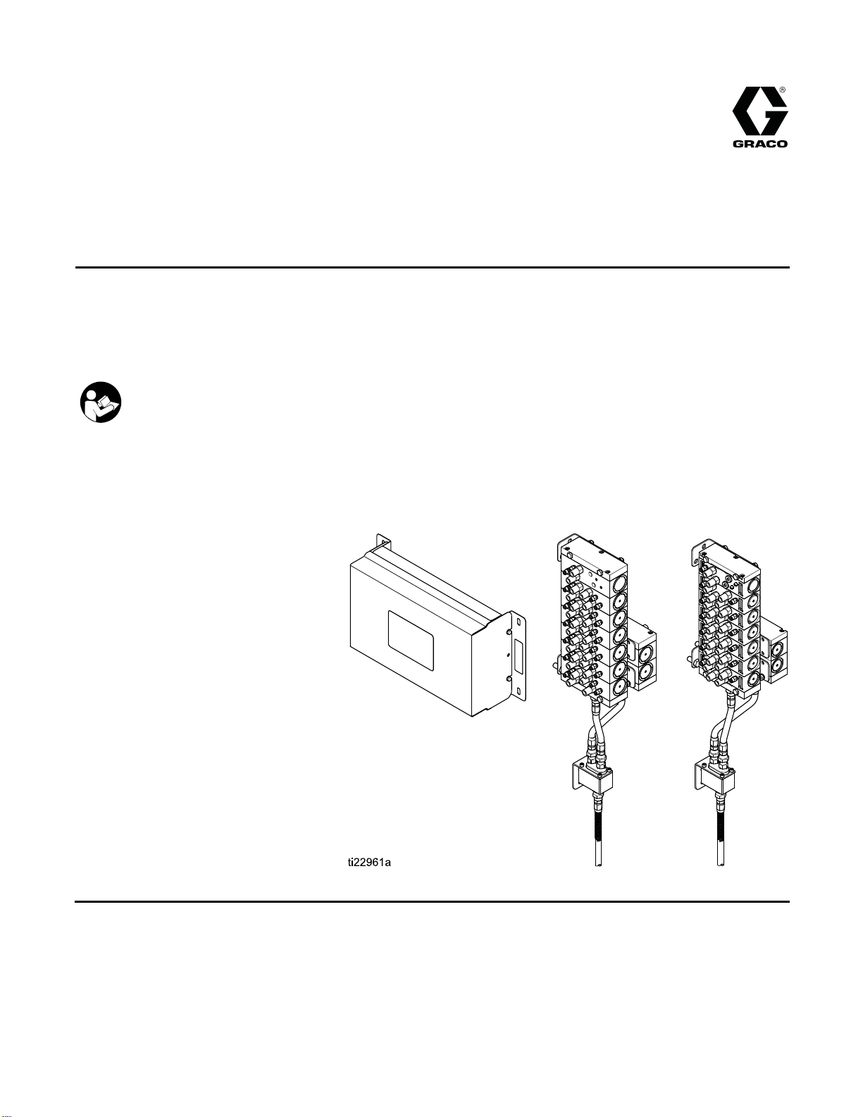
Instructions/Parts
Color Change an
d Remote Mix
333282B
Manifold Kits
To add optional color change function and at-the-gun mixing of two component materials when used
with a ProMix™ PD2K Proportioner for Automatic Spray Applications. For professional use only.
Important Safety Instructions
Read all warnings and instructions in this manual and in your system
installation, operation, and repair/parts manuals.
Save these instructions.
See page 3
approvals information.
for model part numbers and
EN
PROVEN QUALITY. LEADING TECHNOLOGY.
Page 2

Contents
Related Manuals ................................................ 3
Models............................................................... 4
Non-Intrinsically Safe Modules...................... 4
Warnings ........................................................... 9
Important Isocyanate (ISO) Information................ 12
Setup the Modules.............................................. 13
Setup Non-IS Control Modules...................... 13
Setup IS Control Modules............................. 16
Installat
Troubleshooting.................................................. 32
ion.......................................................... 18
Mounting t
Air Supply
Grounding
Non-Hazar
Hazardous
Connect t
Connect t
Install a
he Control Modules ...................... 18
.................................................... 18
................................................... 18
dous Location.............................. 19
Location ..................................... 22
he Valve Air Lines.......................... 24
he Fluid Lines................................ 26
n Expansion Kit ................................ 30
Color Change Solenoid Valves ..................... 32
Color Change Board .................................... 34
Electrical Schematics.......................................... 36
Optional Cables and Modules ....................... 42
Repair................................................................ 43
Replace a Col
Replace a So
Replace the
Replace the
Parts.................................................................. 46
Non-IS Color Change Kits ............................ 46
IS Color Change Kits.................................... 50
Valve Manifold Kits ...................................... 53
Color Change Control Module Kits ................ 64
Expansion Kits............................................. 69
Dimensions ........................................................ 71
Technica
Graco Standard Warranty....................................76
l Data ................................................... 75
or Valve.................................. 43
lenoid...................................... 44
Color Change BoardFuse........... 44
Color Change Board.................. 45
2
333282B
Page 3
Related Manuals
Related Manuals
Current manua
Manual No. Description
332458 PD2K Proportioner, Installation
332564
332565 PD2K Proportioner Repair-Parts
ls are available at www.graco.com.
Manual, Systems for Automatic
Spray Applications
PD2K Propor
Manual, Sys
Spray Appli
Manual, Systems for Automatic
Spray Applications
tioner Operation
tems for Automatic
cations
Manual No. Description
332709 Pump Repair-Parts Manual
332454
332456 3rd and 4th Pump Kits
Color Change
Manual
Instructions-Parts Manual
Valve Repair-Parts
333282B 3
Page 4
Models
Models
Non-Intrinsically Safe Modules
These kits ar
part number.
and certifica
Non-Intri
Kit No.
24R915 A 2 color or 2 catalyst
24R916 A 4 color or 4 catalyst
e installed in the non-hazardous location, near the pumps. See the Kit label for the product
See the module identification label for maximum air working pressure, approval information
tion.
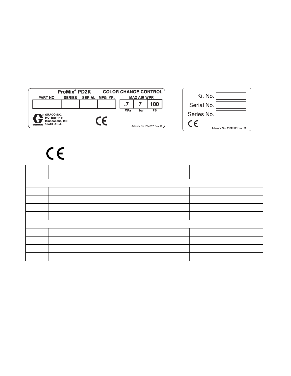
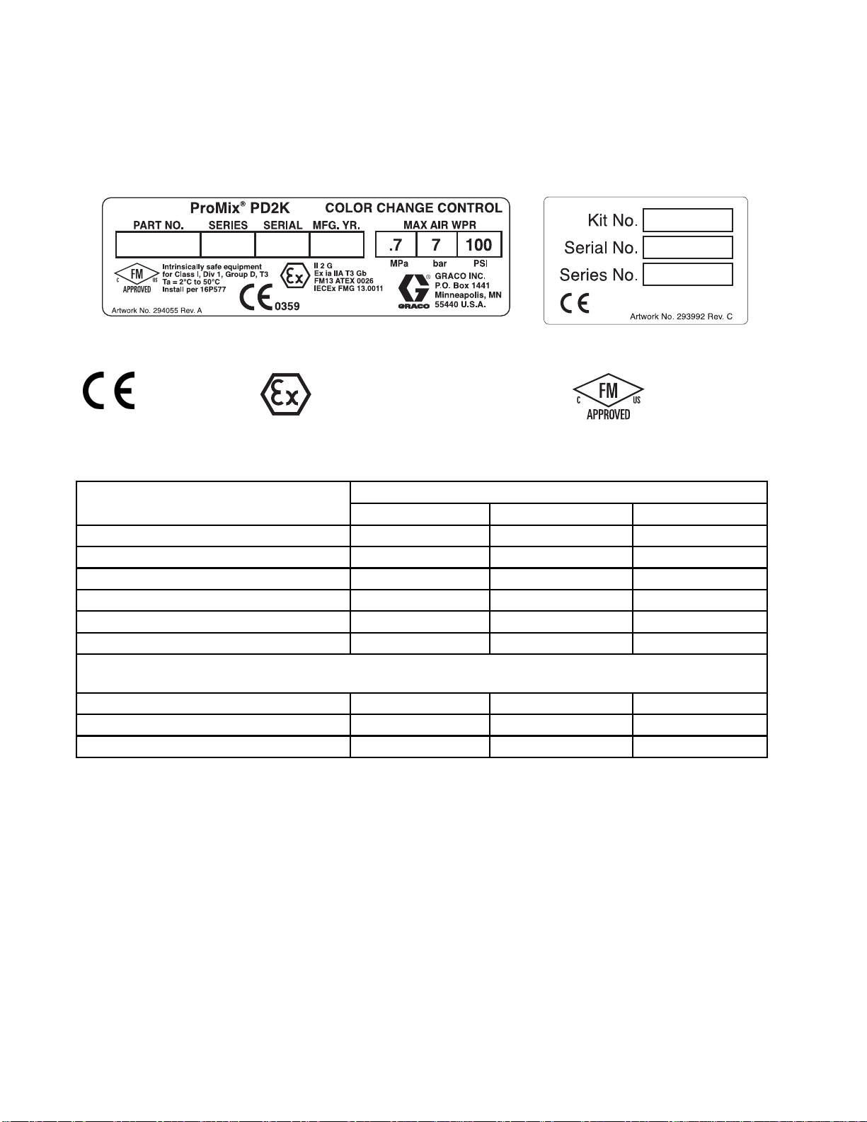
nsically Safe Color Change Control Module Label
Series
Kit Description Maximum Air Working Pressure
Low Pressure Non-Circulating Color Change Kits
Kit Identi
(Control Module)
100 psi (0.7 MPa, 7.0 bar) 300 psi (2.068 MPa, 20.68 bar)
100 psi (0.7 MPa, 7.0 bar) 300 psi (2.068 MPa, 20.68 bar)
fication Label
Maximum Fluid Working
Pressure (Valves)
24R917 A 6 color
24R918 A 8 color
24R919 A 2 color
24R920 A 4 color
24R921 A 6 color
24R922 A 8 color
100 psi (0.7 MPa, 7.0 bar) 300 psi (2.068 MPa, 20.68 bar)
100 psi (0.7 MPa, 7.0 bar) 300 psi (2.068 MPa, 20.68 bar)
Low Pressure Circulating Color Change Kits
100 psi (0.7 MPa, 7.0 bar) 300 psi (2.068 MPa, 20.68 bar)
100 psi (0.7 MPa, 7.0 bar) 300 psi (2.068 MPa, 20.68 bar)
100 psi (0.7 MPa, 7.0 bar) 300 psi (2.068 MPa, 20.68 bar)
100 psi (0.7 MPa, 7.0 bar) 300 psi (2.068 MPa, 20.68 bar)
4
333282B
Page 5

Models
Kit No.
24R959 A 2 color or 2 cat
24R960 A 4 color or 4 catalyst
24R961 A 6 color
24R962 A 8 color
24T579 A
24T580 A
24R963 A 2 color
24R96
24R965 A 6 color
24R966 A 8 color
Series
4
Kit Descriptio
High Press
2 catalyst (acid
compatible)
4 catalyst (acid
compatible)
A4colo
r
n
High Pressure Non-Circulating Color Change Kits
alyst
ure Acid Compatible Non-Circulating Catalyst Change Kits
High Pr
Maximum Air Wor
(Control Modul
100 psi (0.7 MPa, 7.0 bar) 1500 psi (10.34 MPa, 103.4 bar)
100 psi (0.7 M
100 psi (0.7 MPa, 7.0 bar) 1500 psi (10.34 MPa, 103.4 bar)
100 psi (0.7 MPa, 7.0 bar) 1500 psi (10.34 MPa, 103.4 bar)
100 psi (0.7 MPa, 7.0 bar) 1500 psi (10.34 MPa, 103.4 bar)
100 psi (0.7 MPa, 7.0 bar) 1500 psi (10.34 MPa, 103.4 bar)
essure Circulating Color Change Kits
100 psi (0.7 MPa, 7.0 bar) 1500 psi (10.34 MPa, 103.4 bar)
100 psi (0.7 MPa, 7.0 bar) 1500 psi (10.34 MPa, 103.4 bar)
100 ps
100 psi (0.7 MPa, 7.0 bar) 1500 psi (10.34 MPa, 103.4 bar)
i(0.7MPa,7.0bar)
king Pressure
e)
Pa, 7.0 bar)
Maximum Fluid W
Pressure (Valv
1500 psi (10.
1500 p
si (10.34 MPa, 103.4 bar)
orking
es)
34 MPa, 103.4 bar)
NOTE: Systems can use 1 to 30 colors and up to 4
catalysts. To add colors/catalysts:
urrent control module is full: If all solenoid ports
• If c
in use in your control module(s), an additional
are
trol module is needed. Order another complete
con
lor change change kit, shown above.
co
current control module is not full: If empty
• If
lenoid ports remain in your control module, see
so
pansion Kits, page 69.
Ex
333282B 5
Page 6
Models
Intrinsicall
These kits utilize intrinsically safe control modules that are installed in the hazardous area, near the dispense
valve. See the kit identification label for the product part number. See the module identification label for
maximum air working pressure, approval information and certification.
Intrinsically Safe Color Change Module Identification Label Kit Identification Label
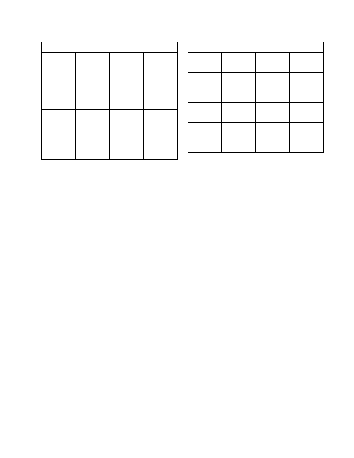
Table 1 . Low Pressure, Non-Circulating Remote Mix Manifold Kits Maximum Fluid Working Pressure: 300 psi (2.07 MPa, 20.7 bar)
Number of Color + Solvent Valves
1 24V157
2 24V158 24V331
4 24V159 24V332 24V343
6 24V160 24V333 24V344
8 24V161 24V334 24V345
12 24V162 24V335 24V346
Control Module Expansion Kits: Use to add a second control module (includes all needed solenoids,
manifolds, valves and a CAN cable).
8
13–1
13–24 24V164
13–30 24V165
y Safe Modules
0359
II 2 G
Number of Catalyst + Solvent Valves
12
63
24V1
4
6 333282B
Page 7
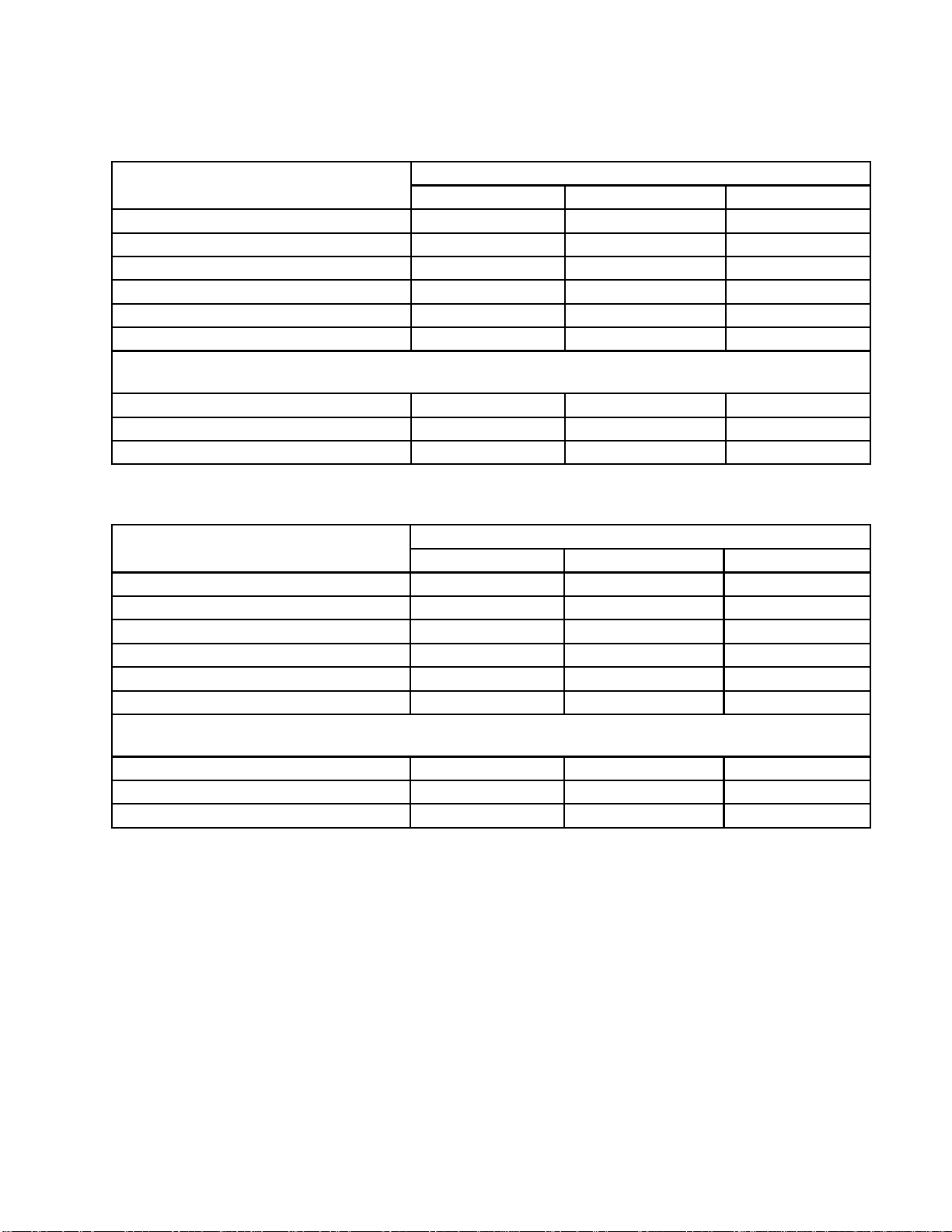
Table 2 . Low Pressure, Circulating Remote Mix Manifold Kits Maximum Fluid Working Pressure: 300 psi (2.07 MPa, 20.7 bar)
Models
Number of Color + Solvent Valves
1 24V166
2 24V167 24V336
4 24V308 24V337 24V347
6 24V309 24V338 24V348
8 24V326 24V339 24V349
12 24V327 24V340 24V350
Control Module Expansion Kits: Use to add a second control module (includes all needed solenoids,
manifolds, valves and a CAN cable).
13–18 24V328
13–24 24V329
13–30 24V330
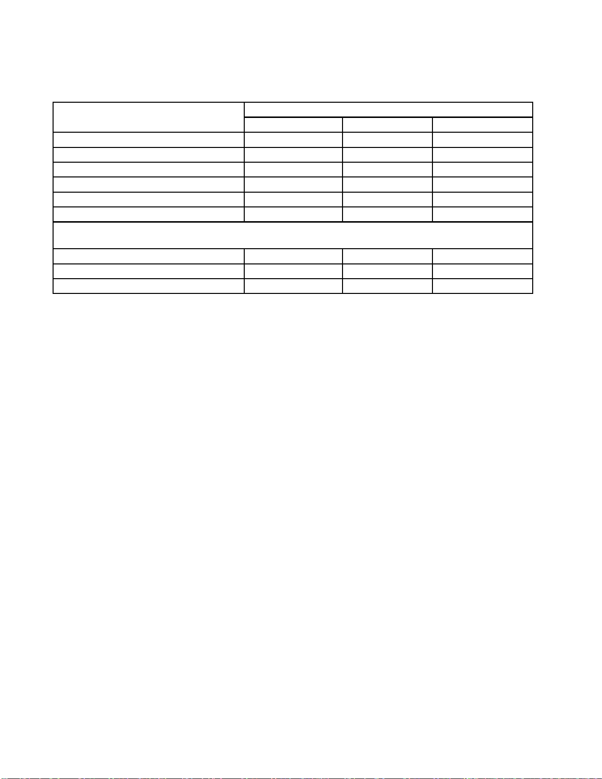
Table 3 . High-Pressure, Non-Circulating Remote Mix Manifold Kits Maximum Fluid Working Pressure: 1500 psi (10.34 MPa, 103.4 bar)
Number of Color + Solvent Valves
1 24V35
2 24V360 24V381
4 24V361 24V382 24V396
6 24V3
8 24V363 24V384 24V398
12 24V364 24V385 24V399
Control Module Expansion Kits: Use to add a second control module (includes all needed solenoids,
manifolds, valves and a CAN cable).
18
13–
13–24 24V366
13–30 24V367
Number of Catalyst + Solvent Valves
12
Number of Catalyst + Solvent Valves
12
9
24V
62
365
24V3
83
Mo
97
24V3
dels continue on next page.
4
4
333282B
7
Page 8
Models
Table 4 . High-Pressure, Circulating Remote Mix Manifold Kits Maximum Fluid Working Pressure: 1500 psi (10.34 MPa, 103.4 bar)
Number of Color + Solvent Valves
1 24V369
2 24V370 24V389
4 24V371 24V390 24V402
6 24V372 24V391 24V403
8 24V373 24V392 24V404
12 24V374 24V393 24V405
Control Module Expansion Kits: Use to add a second control module (includes all needed solenoids,
manifolds, valves and a CAN cable).
13–18 24V375
13–24 24V376
13–30 24V377
NOTE: Systems can use 1 to 30 colors and up to 4 catalysts. To add colors/catalysts:
• If current control module is full: If all solenoid ports are in use in your IS control module, an additional IS
control module is needed. Order a Control Module Expansion Kit, shown above.
• If current control module is not full: If empty solenoid ports remain in your control module, see
Expansion Kits, page 69.
Number of Catalyst + Solvent Valves
12
4
8 333282B
Page 9

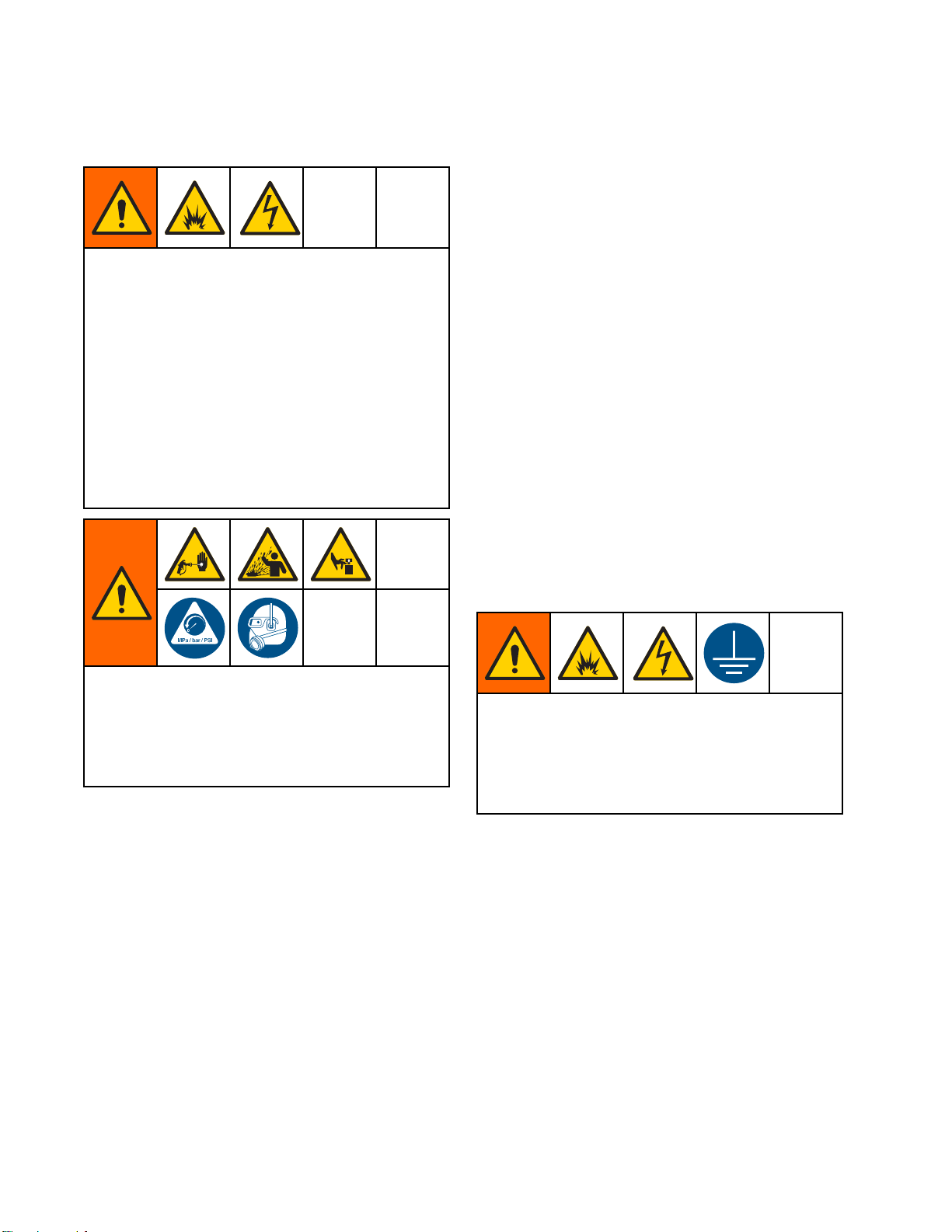
Warnings
Warnings
The following
exclamation p
risks. When th
Warnings. Pr
the body of th
warnings are for the setup, use, grounding, maintenance and repair of this equipment. The
oint symbol alerts you to a general warning and the hazard symbol refers to procedure-specific
ese symbols appear in the body of this manual or on warning labels, refer backtothese
oduct-specific hazard symbols and warnings not covered in this section may appear throughout
is manual where applicable.
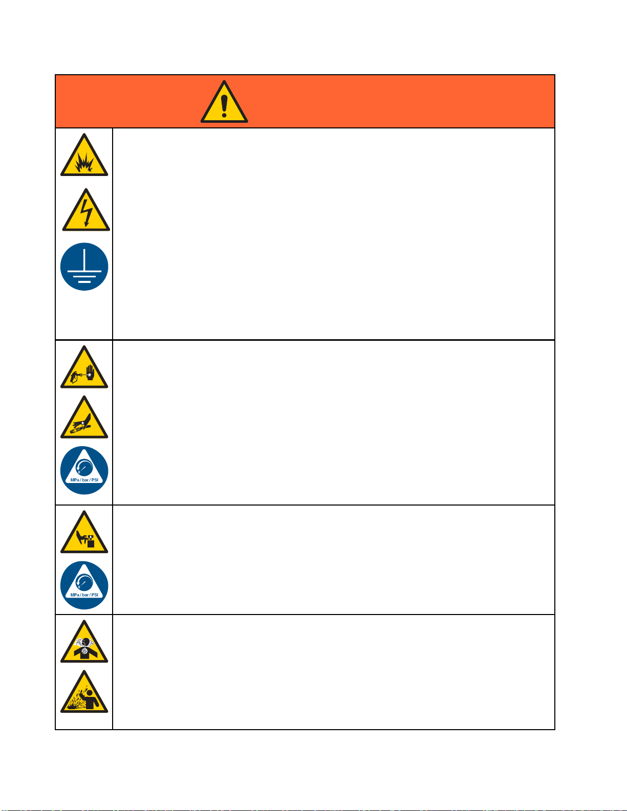
WARNING
FIRE AND EX
Flammable fumes, such as solvent and paint fumes, in work area can ignite or explode. To help
prevent fire and explosion:
• Use equipment only in well ventilated area.
• Eliminate all ignition sources; such as pilot lights, cigarettes, portable electric lamps, and
plastic drop cloths (potential static arc).
•Keepwork
• Do not plug or unplug power cords, or turn power or light switches on or off when flammable
fumes are present.
• Ground all equipment in the work area. See Grounding instructions.
•Useonly
• Hold gun firmly to side of grounded pail when triggering into pail. Do not use pail liners unless
they are antistatic or conductive.
• Stop operation immediately if static sparking occurs or you feel a shock, Do not use
equipment until you identify and correct the problem.
• Keepaw
PLOSION HAZARD
area free of debris, including solvent, rags and gasoline.
grounded hoses.
orking fire extinguisher in the work area.
ELECTRIC SHOCK HAZARD
This equipment must be grounded. Improper grounding, setup, or usage of the system can
cause electric shock.
•Turn
• Connect only to grounded power source.
• All electrical wiring must be done by a qualified electrician and comply with all local codes
333282B 9
off and disconnect power at main switch before disconnecting any cables and before
icing or installing equipment.
serv
and regulations.
Page 10
Warnings
WARNING
INTRINSIC SAFETY
Intrinsical
equipment wi
Follow local
• Be sure your installation complies with national, state, and local codes for the installation of
electrical apparatus in a Class I, Group D, Division 1 (North America) or Class I, Zones 1
and 2 (Europe) Hazardous Location, including all of the local safety fire codes (for example,
NFPA 33, NEC 500 and 516, OSHA 1910.107, etc.).
•Tohelpprev
• Equipment
Safety. T
unit from
SKIN INJECTION HAZARD
High-pr
skin. Th
immedia
• Do not point dispensing device at anyone or at any part of the body.
•Donotp
• Do not stop or deflect leaks with your hand, body, glove, or rag.
• Follow the Pressure Relief Procedure when you stop dispensing and before cleaning,
checking, or servicing equipment.
•Tight
• Check hoses and couplings daily. Replace worn or damaged parts immediately.
ly safe equipment that is installed improperly or connected to non-intrinsically safe
ll create a hazardous condition and can cause fire, explosion, or electric shock.
regulations and the following safety requirements.
ent fire and explosion:
• Do not install equipment approved only for a non-hazardous location in a hazardous
location. See model ID label for the intrinsic safety rating of your model.
• Do not substitute system components as this may impair intrinsic safety.
that comes in contact with the intrinsically safe terminals must be rated for Intrinsic
his includes DC voltage meters, ohmmeters, cables, and connections. Remove the
the hazardous area when troubleshooting.
essure fluid from dispensing device, hose leaks, or ruptured components will pierce
is may look like just a cut, but it is a serious injury that can result in amputation. Get
te surgical treatment.
ut your hand over the fluid outlet.
en all fluid connections before operating the equipment.
MOVING PARTS HAZARD
Moving parts can pinch, cut or amputate fingers and other body parts.
• Keep clear of moving parts.
• Do not operate equipment with protective guards or covers removed.
•Pres
TOX
Tox
inh
• Read MSDSs to know the specific hazards of the fluids you are using.
•St
• Always wear chemically impermeable gloves when spraying, dispensing, or cleaning
surized equipment can start without warning. Before checking, moving, or servicing
pment, follow the Pressure Relief Procedure and disconnect all power sources.
equi
ICFLUIDORFUMES
ic fluids or fumes can cause serious injury or death if splashed in the eyes or on skin,
aled, or swallowed.
ore hazardous fluid in approved containers, and dispose of it according to applicable
idelines.
gu
equipment.
10 333282B
Page 11
Warnings
WARNING
PERSONAL PROTECTIVE EQUIPMENT
Wear appropriate protective equipment when in the work area to help prevent serious injury,
including eye injury, hearing loss, inhalation of toxic fumes, and burns. This protective
equipment includes but is not limited to:
•Protectivee
• Respirators, protective clothing, and gloves as recommended by the fluid and solvent
manufacturer.
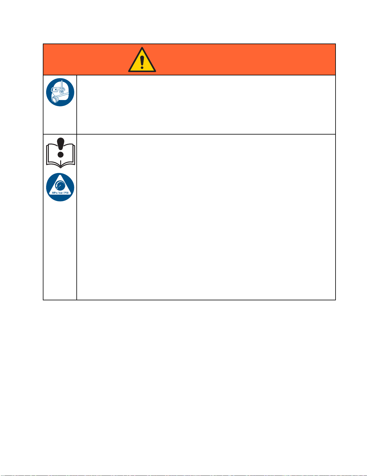
EQUIPMENT MISUSE HAZARD
Misuse can cause death or serious injury.
• Do not operate the unit when fatigued or under the influence of drugs or alcohol.
• Do not exceed the maximum working pressure or temperature rating of the lowest rated
system component. See Technical Data in all equipment manuals.
•Usefluids
in all equ
informat
• Do not leave the work area while equipment is energized or under pressure.
• Turn off all equipment and follow the Pressure Relief Procedure when equipment is not in use.
• Check eq
manufac
• Do not alter or modify equipment. Alterations or modifications may void agency approvals
and create safety hazards.
• Make sure all equipment is rated and approved for the environment in which youareusingit.
•Useequ
• Route hoses and cables away from traffic areas, sharp edges, moving parts, and hot surfaces.
• Do not kink or over bend hoses or use hoses to pull equipment.
•Keepc
• Comply with all applicable safety regulations.
yewear, and hearing protection.
and solvents that are compatible with equipment wetted parts. See Technical Data
ipment manuals. Read fluid and solvent manufacturer’s warnings. For complete
ion about your material, request MSDS from distributor or retailer.
uipment daily. Repair or replace worn or damaged parts immediately with genuine
turer’s replacement parts only.
ipment only for its intended purpose. Call your distributor for information.
hildren and animals away from work area.
333282B
11
Page 12

Important Isocy
anate (ISO) Information
Important Iso
Isocyanates (ISO) are catalysts used in two
component materials.
cyanate (ISO) Information
Isocyanate Conditions
Spraying or dispensing materials containing
isocyanates creates potentially harmful mists,
vapors, and atomized particulates.
Read and understand material manufacturer’s
warnings and material MSDS to know specific
hazards and precautions related to isocyanates.
Prevent inhalation of isocyanate mists, vapors,
and atomized particulates by providing sufficient
ventilation in the work area. If sufficient ventilation
is not available, a supplied-air respirator is required
foreveryoneintheworkarea.
To prevent contact with isocyanates, appropriate
personal protective equipment, including
chemically impermeable gloves, boots, aprons,
and goggles, is also required for everyone in the
work area.
Eventually a film will form on the surface and the ISO
will begin to gel, increasing in viscosity.
NOTICE
Partially c
the life of a
• Always use a sealed container with a desiccant
dryer in the vent, or a nitrogen atmosphere.
Never store ISO in an open container.
• Keep the ISO pump wet cup or reservoir (if
installed) filled with appropriate lubricant. The
lubricant creates a barrier between the ISO and
the atmosphere.
• Use only moisture-proof hoses compatible with
ISO.
• Never use reclaimed solvents, which may
contain moisture. Always keep solvent
containers closed when not in use.
• Always lubricate threaded parts with an
appropriate lubricant when reassembling.
NOTE: The amount of film formation and rate of
crystallization varies depending on the blend of ISO,
the humidity, and the temperature.
ured ISO will reduce performance and
ll wetted parts.
Keep Components A and B Separate
Cross-contamination can result in cured
material in fluid lines which could cause serious
injury or damage equipment. To prevent
cross-contamination:
• Never interchange component A and component
B wetted parts.
• Never use solvent on one side if it has been
contaminated from the other side.
Moisture Sensitivity of Isocyanates
Exposure to moisture (such as humidity) will cause
ISO to partially cure; forming small, hard, abrasive
crystals, which become suspended in the fluid.
Chang
Changing the material types used in your
equipment requires special attention to avoid
equipment damage and downtime.
•When
•Alw
•Che
•Wh
ing Materials
NOTIC
changing materials, flush the equipment
tiple times to ensure it is thoroughly clean.
mul
ays clean the fluid inlet strainers after
hing.
flus
ck with your material manufacturer for
mical compatibility.
che
en changing between epoxies and urethanes
polyureas, disassemble and clean all fluid
or
mponents and change hoses. Epoxies often
co
ve amines on the B (hardener) side. Polyureas
ha
ten have amines on the A (resin) side.
of
E
2
1
333282B
Page 13
Setup the Module
s
Setup the Modu
Setup Non-IS C
NOTE: The PD2K System can use up to four pumps
and six color change modules in the non-hazardous
area. Use the following table to understand how
many color change modules are needed for the
number of pumps in your system, and which module
should be associated to which pump.
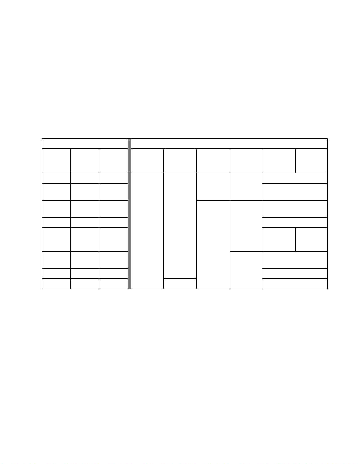
Table 5 . Relationship of Non-IS Color Change Control Modules to Pumps
System Pum
Color
Pump(s)
1 0 1 Not Appli
112
213
p Configuration
Catalyst
Pump(s)
ontrol Modules
Total
Pumps
les
Module 1
(Colors
1–8)
Color Chan
Module 2
(Colors
9–16)
All Non-IS modules ship from the factory as Module
1 (Colors 1–8). Labels for Modules 2 through 6
are provided with the module kit. Affix the labels
according to your system configuration.
ge Control Modules, Colors, and Catalysts
Module
3(Colors
17–24)
Pump # 1 Pump # 1
Module 4
(Colors
25–30)
Catalyst
1–2
Module # 5
Pump # 2
Module # 5
Pump # 2
Catalyst
3–4
cable
2 0 2 Not Applicable
Pump#1
224
314
303
404
Pump#1
Pump #
Pump#2
3
Pump # 3
Pump # 4
e
Modul
#5
Pump #
2
Module # 5
Pump # 2
Not A
Not Applicable
Modul
#6
Pump #
pplicable
e
4
333282B 13
Page 14
Setup the Module
s
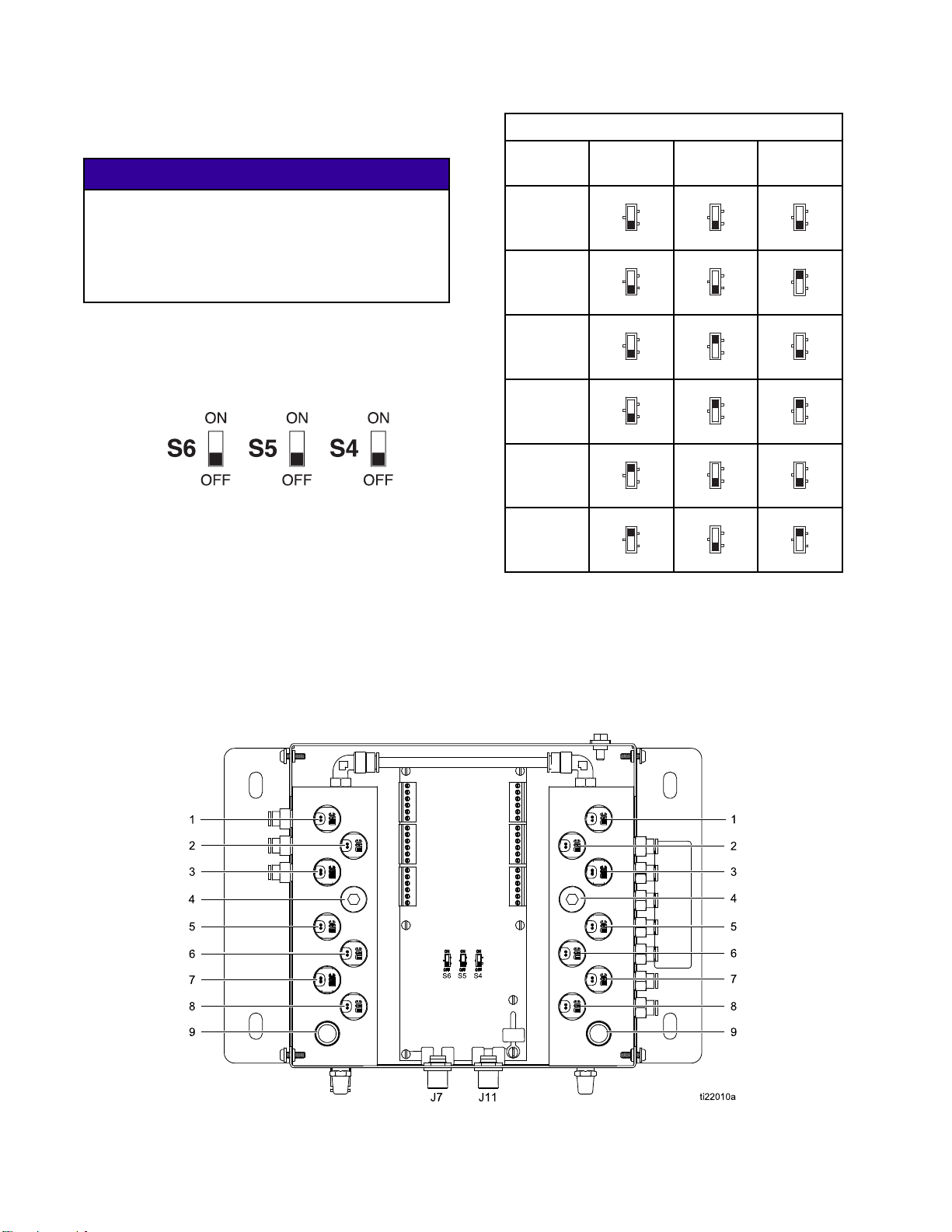
Configure each module according to its designated
number, as follows:
NOTICE
To avoid damaging the circuit boards, wear Part
No. 112190 grounding strap on your wrist and
ground appropriately.
To avoid elec
system power
1. Remove elec
2. Open the col
S4, S5, and S
switches a
3. For each module, set the switches to ON or OFF,
as shown in the following table.
trical component damage, remove all
before plugging any connectors.
trical power from the system.
or change module. Locate switches
6onthecontrolmoduleboard. The
re shipped in the OFF position.
Non-IS Control Module Switch Settings
Control
S6 S5 S4
Module
Module 1
Module 2
Module 3
Module 4
Module 5
Module 6
ON
OFF
ON
OFF
ON
OFF
ON
OFF
ON
OFF
ON
OFF
ON
OFF
ON
OFF
ON
OFF
ON
OFF
ON
OFF
ON
OFF
ON
OFF
ON
OFF
ON
OFF
ON
OFF
ON
OFF
ON
OFF
4. Use the following figure and tables to determine
the solenoid valve assigned to each valve in the
valve manifold.
NOTE: There can be only one solvent valve and one
dump valve per pump.
Inlet Manifold Outlet Manifold
Figure 1 Non-IS Control Module
4
1
333282B
Page 15
Setup the Module
s
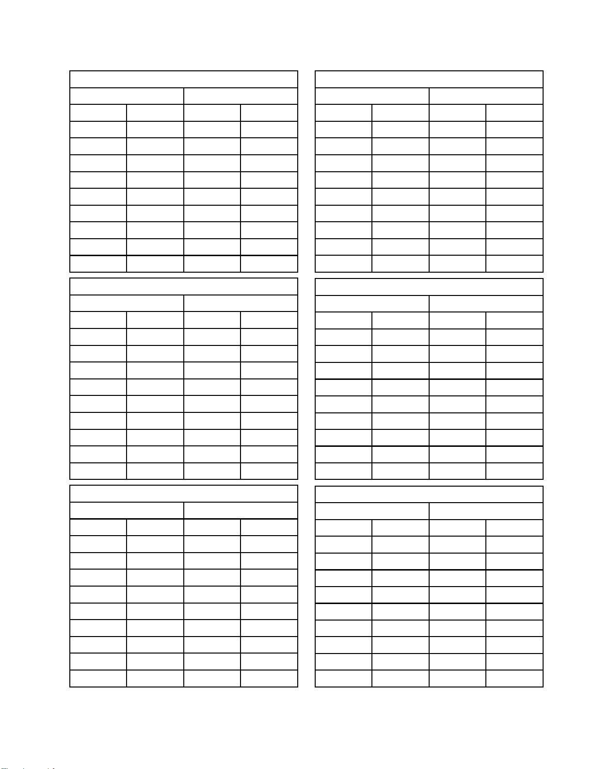
Non-IS Control Module 1
Inlet Manifol
Solenoid
1
2
3
4
5
6
7
8
9
Inlet Manifold Outlet Manifold
Solenoid
1
2
3
4
5
6
7
8
d
Valve
Solvent
Color 1
Color 2
Color 3
Color 4
Color 5
Color 6
Color 7
Color 8
Non-IS Control Module 2
Valve
(Solvent)*
Color 9
Color 10
Color 11
Color 12
Color 13
Color 14
Color 15
Outlet Manifo
Solenoid
1Dump
2
3
4
5
6
7
8
9
Solenoid
1
2
3
4
5
6
7
8
ld
Valve
Color 1
Color 2
Color 3
Color 4
Color 5
Color 6
Color 7
Color 8
Valve
(Dump)*
Color 9
Color 10
Color 11
Color 12
Color 13
Color 14
Color 15
Non-IS Control Module 4
Inlet Manifol
Solenoid
1
2
3
4
5
6
7
8 Not Used 8 Not Used
9NotUse
Inlet Manifold Outlet Manifold
Solenoid
1
2
3
4
5
6 Not Used 6 Not Used
7
8 Not Used 8 Not Used
d
Valve
(Solvent)*
Color 25
Color 26
Color 27
Color 28
Color 29
Color 30
d
Non-IS Control Module 5
Valve
(Solvent)*
Catalyst 1
Catalyst 2
Catalyst 3
Catalyst 4
Not Used
Outlet Manifo
Solenoid
1
2
3
4
5
6
7
9NotUse
Solenoid
1
2
3
4
5
7
ld
Valve
(Dump)*
Color 25
Color 26
Color 27
Color 28
Color 29
Color 30
Valve
(Dump)*
Catalyst 1
Catalyst 2
Catalyst 3
Catalyst 4
Not Used
d
9
Inlet Manifold Outlet Manifold
Solenoid
1
2
3
4
5
6
7
8
9
* There should be only one solvent valve and one dump valve per pump.
Color 16
Non-IS Control Module 3
Valve
(Solvent)*
Color 17
Color 18
Color 19
Color 20
Color 21
Color 22
Color 23
Color 24
9
Solenoid
1
2
3
4
5
6
7
8
9
Color 16
Valve
(Dump)*
Color 17
Color 18
Color 19
Color 20
Color 21
Color 22
Color 23
Color 24
9 Not Used 9 Not Used
Non-IS Control Module 6
Inlet Manifold Outlet Manifold
Solenoid
1
2
3
4 Not Used 4 Not Used
5
6 Not Used 6 Not Used
7
8 Not Used 8 Not Used
9 Not Used 9 Not Used
Valve
(Solvent)*
Catalyst 3
Catalyst 4
Not Used
Not Used
Solenoid
1
2
3
5
7
Valve
(Dump)*
Catalyst 3
Catalyst 4
Not Used
Not Used
333282B 15
Page 16
Setup the Module
s
Setup IS Contr
ol Modules
NOTE: Two IS color change control modules may
be installed in the hazardous area. The module
for colors 1–12 is labeled board 7. The module for
colors 13–30 is labeled board 8. An alternate label
for Module 8 (Colors 13–30) is provided with the
module kit. Affix the label according to your system
configuration.
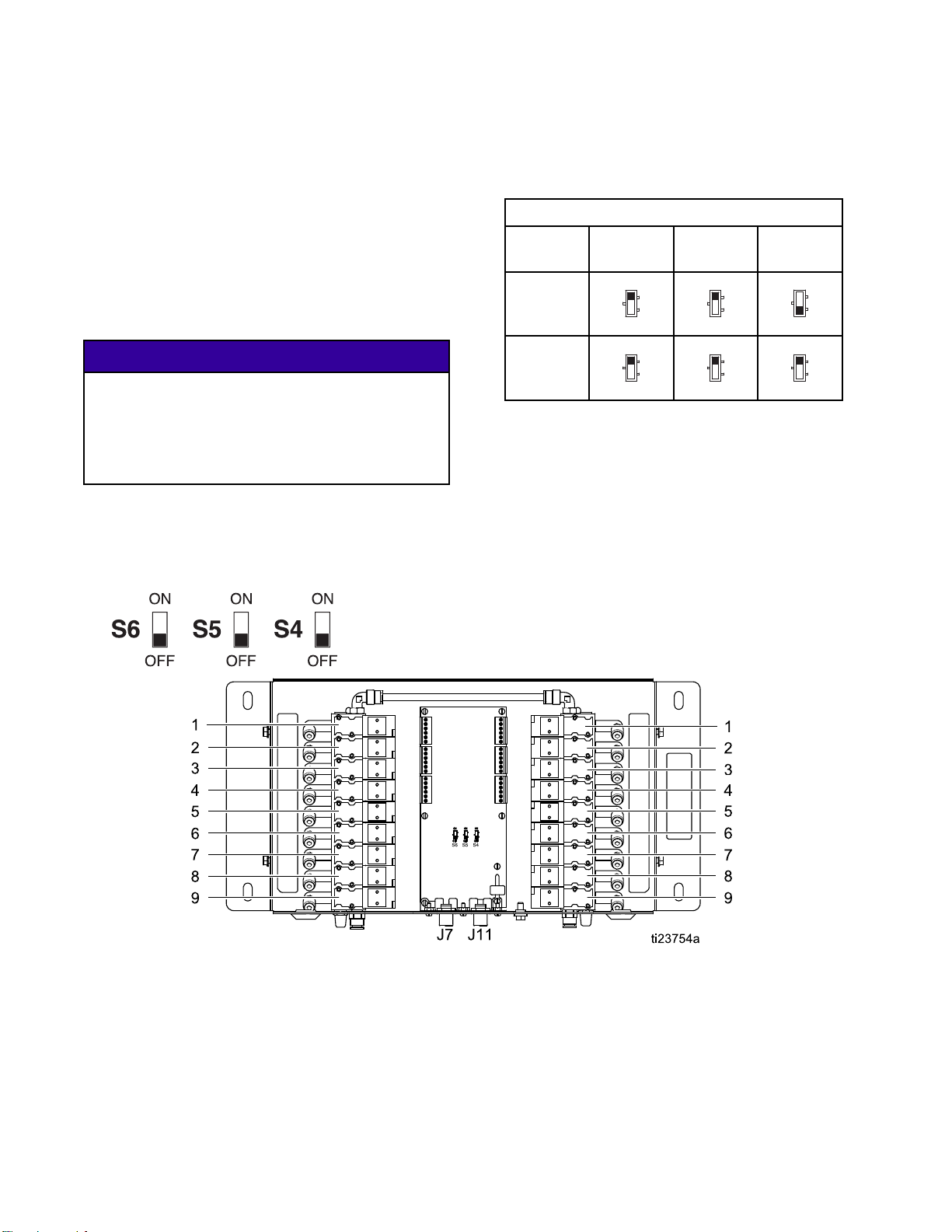
Configure ea
number, as f
ch module according to its designated
ollows:
NOTICE
To avoid da
No. 112190
ground app
To avoid electrical component damage, remove all
system power before plugging any connectors.
1. Remove electrical power from the system.
2. Open the color change module. Locate switches
S4, S5, and S6 on the control module board. The
switches may be shipped in the OFF position.
maging the circuit boards, wear Part
grounding strap on your wrist and
ropriately.
3. For each module, set the switches to ON or OFF,
as shown in the following table.
IS Control Mod
Control
ule Switch Settings
S6 S5 S4
Module
Module 7
Module 8
ON
OFF
ON
OFF
ON
OFF
ON
OFF
ON
OFF
ON
OFF
4. Use the following figure and tables to determine
the solenoid valve assigned to each valve in the
valve manifold.
Figure 2 IS Control Module
16 333282B
Page 17
Setup the Module
s
Solenoid
1
2
3
4
5
6
7
8
9
IS Control Module 7
Valve
Color
Solvent
Color 1
Color 2
Color 3
Color 4
Color 5
Color 6
Color 7
Color 8
Solenoid
1
2
3
4
5
6
7
8
9
Valve
Catalyst
Solvent
Catalyst 1
Catalyst 2
Catalyst 3
Catalyst 4
Color 9
Color 10
Color 11
Color 1
2
Solenoid
1
2
3
4
5
6
7
8
9
IS Control Module 8
Valve
Color 13
Color 14
Color 15
Color 16
Color 17
Color 18
Color 19
Color 20
Color 2
1
Solenoid
1
2
3
4
5
6
7
8
9
Valve
Color 22
Color 23
Color 24
Color 25
Color 26
Color 27
Color 28
Color 29
Color 3
0
333282B
17
Page 18
Installation
Installation
• To avoid electric shock, turn off power at
the main circuit breaker before opening the
enclosure.
• All electrical wiring must be done by a qualified
electrician and comply with all local codes and
regulations.
• Do not substitute or modify system components
as this may impair intrinsic safety.
• Do not install equipment approved only for
non-hazardous location in a hazardous location.
See the identification label for the intrinsic safety
rating for your model.
3. Using the equipment as a template, mark the
mounting holes on the wall at a convenient height
for the operator and so the equipment is easily
accessible for maintenance.
NOTE: The smaller color change control modules
must be mounted in the Non-IS area. The larger
remote color change module may be mounted
in the IS area.
4. Drill mounting holes in the wall. Install anchors
as needed.
5. Bolt the equipment securely.
Air Supply
Connect a clean and dry air supply to the air inlet
fitting (317) of each color change control module in
the non-hazardous area and each remote module in
the hazardous area. The fitting is for 1/4 in. (6 mm)
ODtubing. Usea5micronfilter. Regulatetheair
pressure to 85–100 psi (0.6–0.7 MPa, 6.0–7.0 bar).
This equipment stays pressurized until pressure
is manually relieved. To help prevent serious
injury from pressurized fluid, such as skin injection,
splashing fluid and moving parts, follow the
Pressure Relief Procedure in the PD2K Operation
Manual before installing the kit.
Mounting the Control Modules
1. See Dimensions, page 71.
2. Ensure that the wall and mounting hardware
are strong enough to support the weight of the
equipment, fluid, hoses, and stress cause during
operation.
Grounding
This equipment must be grounded to reduce the
risk of static sparking and electric shock. Electric
or static sparking can cause fumes to ignite or
explode. Improper grounding can cause electric
shock. Grounding provides an escape wire for the
electric current.
Connect a ground wire from each color change
module in the non-hazardous area to a true earth
ground.
Intrinsically safe remote color change modules
located in the hazardous area must be connected to
a true earth ground in the hazardous area.
18 333282B
Page 19

Non-Hazardous Location
Connect the Color Change Control Modules
NOTE: Non-IS color change control modules provide
control for the pump’s inlet and outlet color/catalyst
change valves. Depending on the number of valves
in the system, as many as six control modules may
be installed in the non-hazardous location.
1. Mount the first non-IS color
control module as described in
Mounting the Control Modules, page 18.
2. Connect the 5–pin CAN cable (109) to J7 on the
color control module (108).
Installation
7. To install additional color control modules (six
maximum), mount the module(s) as described in
Mounting the Control Modules, page 18. Connect
a 5–pin CAN cable from J11 of the previous color
control module to J7 of the next control module.
8. Replace the cover of the PD2K electrical control
box before turning on power to the system.
Figure 3 Cable Connector J7 at Non-IS Color
Control Module
NOTICE
To avoid damaging the circuit boards, wear
Part No. 112190 grounding strap on your wrist
and ground appropriately.
To avoid electrical component damage,
remove all system power before plugging any
connectors.
3. Remove electrical power from the system.
4. Remove the cover from the PD2K electrical
control box.
5. Install the supplied 2–cable grommet (110) on
the cable (109) and secure the grommet to the
side of the electrical control box.
6. Connect the cable (109) to J2 on the non-IS side
of the isolation board inside the electrical control
box. See Electrical Schematics, page 36 for a list
of M12 CAN cables for use in a non-hazardous
area.
Figure 4 Cable Connection at PD2K Electrical
Control Box
Figure 5 Detail of Isolation Board Cable Connections
333282B 19
Page 20

Installation
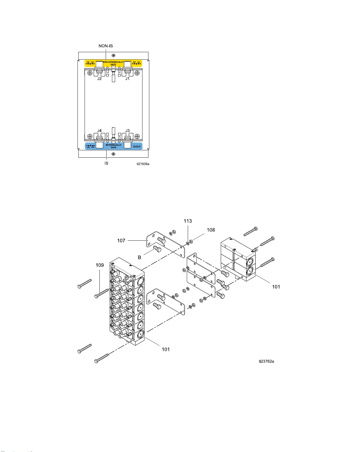
Install the Valve Manifolds
NOTE: Always label the color connections to prevent
cross-connections. Label the inlet manifold, outlet
manifold, and each color valve with its assigned color.
The solvent and dump valves should be furthest from
the manifold stack primary inlet or outlet.
1. Install a mou
with four scr
For stabilit
(103) to the
nting bracket (101) on the PD2K
ews (103). High pressure systems:
y, be sure to fasten the bottom screws
pump bracket.
with 16 valve positions (14 colors). On high
pressure systems, the supplied bracket (101) will
accommodate a manifold with 14 valve positions
(12 colors). A larger valve stack will require a
customer supplied/sourced bracket.
3. Repeat for the opposite side of the PD2K.
4. Connect the air lines from the solenoids to the
valves. See Connect the Valve Air Lines, page 24.
NOTE: On high pressure systems, see
Install the Back Pressure Regulator (High
Pressure Systems Only), page 21.
5. Connect the fluid supply lines to the valves. See
Connect the Fluid Lines, page 26.
2. Install the inlet and outlet valve manifolds (102)
on the mounting bracket (101) with four screws
(104), washers (105), and nuts (106).
NOTE: On low pressure systems, the supplied
bracket (101) will accommodate a manifold
Figure 6 Install the Valve Manifolds
20 333282B
Page 21
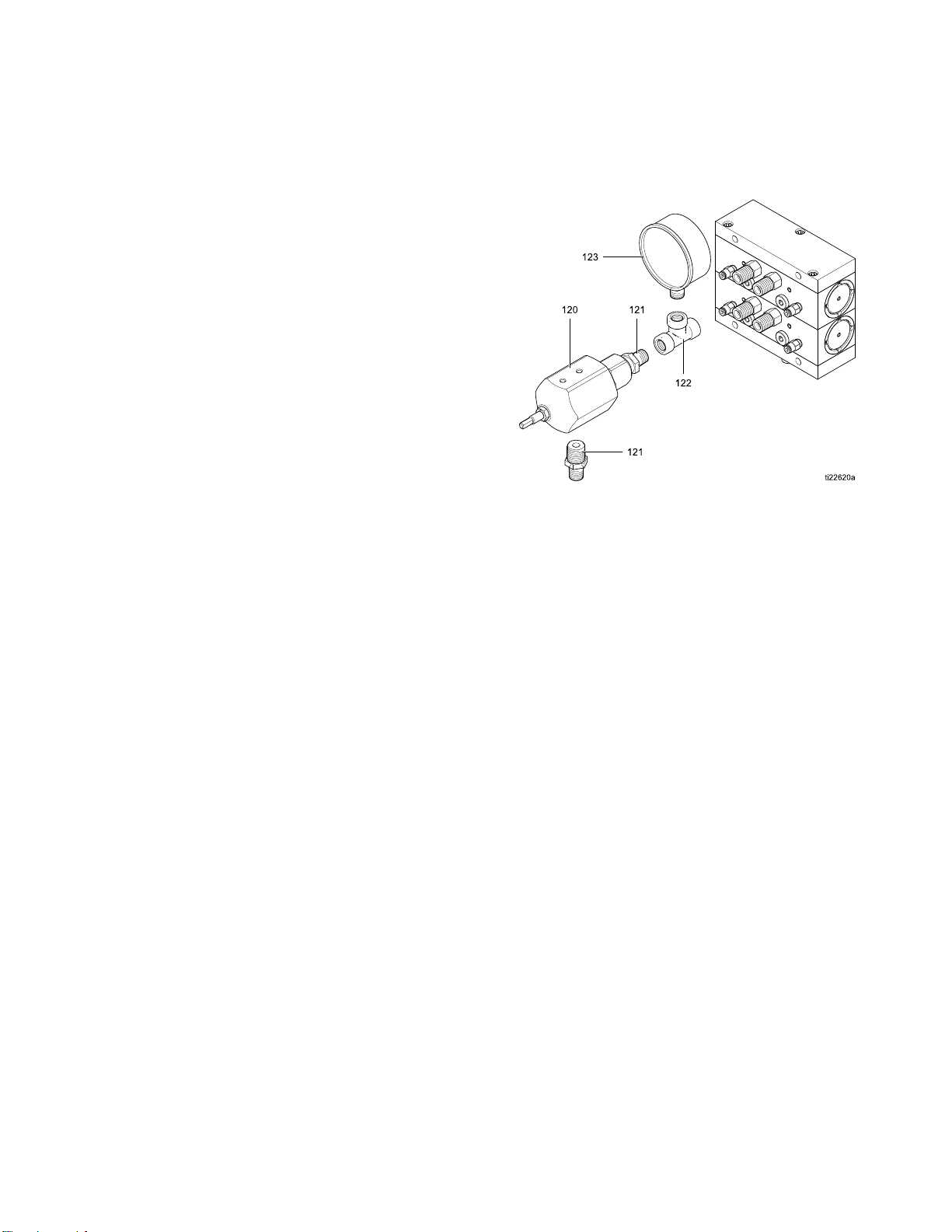
Install the Back Pressure Regulator (High Pressure Systems Only)
Installation
NOTE: The back pressure regulator is required on
high pressure systems to prevent the system’s feed
pumps from overdriving the dosing pumps during
color change pump flush and color fill operations.
Adjust the back pressure during the dump process to
be approximately 75% of the supply pressure from
the feed pumps, but never more than 300 psi (2.1
MPa, 21 bar) less than the supply pressure.
Install the
attaching h
manifold st
1. Install the gauge (123) in the open port of the
2. Screw the tee (122) onto the dump valve fitting of
3. Assemble the two nipples (121) to the back
4. Connect a 1/4 npt(f) dump line to the downward
back pressure regulator (120) and
ardware at the dump valve of the outlet
ack.
tee (122).
the outlet manifold stack.
pressure regulator (120). Screw the regulator
assembly into the tee (122) as shown.
facing nipple (121).
5. Connect the fluid supply lines to the valves. See
Connect the Fluid Lines, page 26.
Figure 7 I
Valve of O
nstall Back Pressure Regulator at Dump
utlet Stack
333282B
21
Page 22

Installation
Hazardous Location
Connect Remot
e Color Change Control
Module
NOTE: IS color change control modules
provide control for remote color/catalyst change
valves located in the hazardous location
for use with automatic spray systems. A
maximum of two IS control modules may
be installed in the hazardous location. See
IS Color Change Control Modules, page 66 for a list
of modules approved for installation in a hazardous
location.
NOTICE
To avoid damaging the circuit boards, wear Part
No. 112190 grounding strap on your wrist and
ground appropriately.
To avoid electrical component damage, remove all
system power before plugging any connectors.
Figure 8 Intrinsically Safe Cable Connections
3. Connect the hazardous location cable (C1) to J7
on the remote color control module (108).
Only approved cables may be used in the
hazardous location. Hazardous location cables are
marked with a light blue flag next to each connector.
See Optional Cables and Modules, page 42 for a
list of M12 CAN cables for use in a hazardous area.
1. Remove electrical power from the system.
2. Mount the first remote color change
control module as described in
Mounting the Control Modules, page 18.
Figur
Color
4. Remo
rol box. Install the grommet (G) on the
cont
supp
to th
J4 on
ctrical control box. Connect the cable (C1) to
ele
See Electrical Schematics, page 36.
J4.
e 9 Cable Connectors J7 and J11 at IS
Control Module
ve the cover from the PD2K electrical
lied cable (C1) and secure the grommet
e side of the electrical control box. Locate
theISsideoftheisolationboardinthe
2
2
333282B
Page 23
Installation
J11onthefirst color control module to J7 on the
second module.
6. Replace the cover of the PD2K electrical control
box before turning on power to the system.
Install the Remote Valve Manifolds
1. Using the equipment as a template, mark the
mounting holes on the wall at a convenient height
for the operator and so the equipment is easily
accessible for maintenance. Mount the remote
valve manifolds near the remote color module
and the automatic dispensing device.
2. Install the mounting brackets for the color valve
manifolds and the catalyst valve manifolds. See
Dimensions, page 71. Use bolts to attach the
equipment securely.
Figure 10 Detail of Isolation Board Cable
Connections
5. If your system includes a second remote
color control module mount it as described in
Mounting the Control Modules, page 18. Connect
the supplied hazardous location cable (C2) from
3. Install the color and catalyst valve manifolds to
the brackets with four screws, washers, and nuts.
4. Connect the air lines from the solenoids to the
valves. See Connect the Valve Air Lines, page 24.
5. Connect the fluid supply lines to the valves. See
Connect the Fluid Lines, page 26.
333282B 23
Page 24

Installation
Install the Remote Mix Manifold
1. Using the equipment as a template, mark the
mounting holes on the wall or robot arm, near the
automatic dispensing device.
2. Install the remote mix manifold. See
Dimensions, page 71. Use two bolts to attach
the equipment securely.
3. Install the remote mix manifold to the bracket
with four screws.
4. Connect the fluid supply lines to the remote mix
valve. See Connect the Fluid Lines, page 26.
Connect the Va
Non-Hazardous Area
1. Connect 5/32 i
inlet soleno
using the lab
as a guide. Se
2. Repeat for th
Hazardous Area
Connect 5/32 in (4 mm) OD air tubes from the
solenoids to the air inlet of each valve, using the
labels inside of the remote color control module as a
guide. See Setup the Modules, page 13.
lve Air Lines
n. (4 mm) OD air tubes from the
ids to the air inlets of each inlet valve,
el inside of the color control module
e Setup the Modules, page 13.
e outlet valves.
4
2
333282B
Page 25

Notes
Installation
333282B 25
Page 26

Installation
Connect the Fl
uid Lines
Connect Non-Circulating Fluid Lines
NOTE: There can be only one solvent valve (S) and
one dump valve (D) per pump.
NOTE: On high
Install the
Systems Onl
1. Use the top valve of the inlet valve stack as the
solvent valve (S). Connect a solvent supply line
to the 1/4 npt(m) solvent valve inlet on the color
and catalyst valve stacks.
Hazardo
us
Area
pressure systems, see
Back Pressure Regulator (High Pressure
y), page 21.
2. Usethetopvalveoftheoutlet valve stack as the
dump valve (D). Connect a waste dump line to
the 1/4 npt(m) dump valve outlet on the color and
catalyst valve stacks.
3. Connect the supply line for each color to the
corresponding color valve fitting (C1, C2, etc.) on
the inlet color valve stack.
4. Connect a supply line from the bottom fitting of
the inlet color valve stack to the inlet manifold of
the material A dosing pump.
5. Connect a supply line from the outlet manifold of
the material A dosing pump to the bottom fitting
of the outlet color valve stack.
Remote
Color an
Catalys
Manifol
d
t
Valve
ds
Non-
Hazardous
Area
Valve Manifold Stack Schematic
Non-IS
inlet and
outlet
color and
catalyst
valve
manifolds
26 333282B
Page 27

Installation
6. Connect a dedicated supply line for each color
to the corresponding color valve fitting (C1, C2,
etc.) on the outlet color valve stack. Connect the
other end of each line to the corresponding color
valvefittingontheremotecolorstack.
7. Connect a supply line from the outlet valve on
the bottom of the remote color valve stack to inlet
A on the remote mix manifold.
8. Connect the supply line for each catalyst to the
corresponding catalyst valve fitting on the inlet
catalyst valve stack.
9. Connect a supply line from the bottom fitting of
the inlet catalyst valve stack to the inlet manifold
of the material B dosing pump.
10. Connect a supply line from the outlet manifold of
the material B dosing pump to the bottom fitting
of the outlet catalyst valve stack.
11. Connect a dedicated supply line for each catalyst
to the corresponding catalyst valve fitting on the
outlet catalyst valve stack. Connect the other
end of each line to the corresponding catalyst
valve fitting on the remote catalyst valve stack.
NOTE: If your system uses more colors than
catalysts, branch the catalyst line to connect it to
each mix manifold. Install a check valve on each
branch of the catalyst line.
NOTE: For ease of maintenance, install a ball
valve at all fluid line tees.
13. Connect the static mixer to the outlet valve of the
remote mix manifold.
14. Connect a fluid line from the static mixer to the
automatic dispense device.
Figure 11
(Non-Cir
KEY
A Air inlet
W
S Solvent fitting
C1 Color 1 fitting
C2 Color
Color Change Connections
culating System)
Seal wee
lubrica
pand
tion port
2fitting
12. Connect a supply line from the outlet valve of
the remote catalyst valve stack to inlet B on the
remote mix manifold.
333282B
27
Page 28

Installation
Connect Circulating Fluid Lines
Circulation valves enable constant circulation of a
color when that color is not being sprayed:
•Whenacolorva
the dosing pum
inlet color v
remote color
back to the co
• When a color v
shut off. Th
A dosing pum
stack and mi
NOTE: On circulating systems, install a cap (T) on
any unused valve fittings.
NOTE: There can be only one solvent valve (S) and
one dump valve (D) per pump.
NOTE: On h
Install t
Systems O
1. Connect all fluid lines as described in
2. Connect the circulation lines as follows:
he Back Pressure Regulator (High Pressure
nly), page 21.
Connect Non-Circulating Fluid Lines, page 26.
These lines are used during normal mixing and
spraying.
a. Connect a 1/4 npt(f) circulation line for each
color from the color valve’s circulation fitting
(R1, R2, etc.) on the inlet color valve stack
(B) to the corresponding circulation fitting
(R1, R2, etc.) on the outlet color valve
stack (C). This circulation line bypasses the
material A dosing pump when the color valve
is closed, allowing continuous circulation of
that color.
lve is closed, the system bypasses
p by directing that color from the
alve to the outlet color valve to the
valve, through a circulation line, then
lor supply.
alve is open, the circulation line is
e color is directed through the material
p and out to the remote color valve
x manifold, as in normal operation.
igh pressure systems, see
b. Connect a dedicated fluid supply line for
each color to the corresponding color valve
(C1, C2, etc.) on the outlet color valve stack.
Connect the other end of each line to the
corresponding color valve on the remote
color stack.
c. Connect a 1/4 n
circulation
thefluidsupp
Figure 12 Valve Manifold Connections (Circulating
System)
KEY
D
Dump valve fitting
S Solvent fitting
C1 Color 1
C2 Color 2 fitting
R1
Color 1 circulation fitting
R2
Colo
fitting
r 2 circulation fitting
pt(f) circulation line from the
port on each remote valve back to
ly container.
28 333282B
Page 29

KEY
A
Color supply
Installation
Fluid Flow Schematic Diagram in Circulating Mode (Pump Not Shown for Clarity)
BInletcolo
C Outlet color stack
DRemoteco
E
Remote mix manifold
F Automa
G Return line to fluid supply
rstack
lor stack
tic spray gun
333282B 29
Page 30

Installation
Install an Expansion Kit
Expansion Kits are available to add valves or
manifolds to your system. For each additional
color/catalyst desired, order a Non-IS Expansion
Kit and a corresponding IS Expansion Kit. See
Expansion Kits, page 69 for available kits.
NOTE: Remember that you may need up to 6 Non-IS
control modules and up to 2 IS control modules.
Follow Steps 1–7 to install solenoids, manifolds, and
valves, first in the Non-IS area, and then in the IS
area.
1. Remove electrical power from the system.
2. Relieve pressure as described in your PD2K
Operation Manual.
3. Open the control module cover. Install the
solenoid(s) and air fitting(s) at the appropriate
position(s) in the solenoid manifold. See
Setup the Modules, page 13. Connect one end
of the tubing to the solenoid’s air fitting.
6. Install the valves as follows:
a. For a one valve kit, remove the plug
(4) and o-ring (2). Install a new o-ring
(2), the valve (3), and retainer (5),
using the valve installation tool. See
Replace a Color Valve, page 43.
b. For a manifold kit with one valve, install
the o-ring (2), valve (3), and retainer (5),
using the valve installation tool. See
Replace a Color Valve, page 43.Installthe
plug (4) in the unused manifold port.
c. For a manifold kit with two valves, install
the o-rings (2), valves (3), and retainers
(5), using the valve installation tool. See
Replace a Color Valve, page 43.
7. Install the o-ring(s) (12) and fluid fitting(s) (13).
8. For each color/catalyst, connect fluid lines from
the source to the input color/catalyst stack. Then,
connect fluid lines from each output valve to the
corresponding remote color change valve.Install
the air fitting(s) (14).
9. Connect the tubing from the solenoid valve(s)
(see step 3) to the fitting(s) in both the IS and
and Non-IS areas.
10. Install the control module covers.
11. Return the unit to service.
4. Connect the solenoid wires to the appropriate
pins on the control module board. See
Electrical Schematics, page 36.
NOTE: If installing a one valve kit, it is not
necessary to disassemble the manifold stack as
shown in the figure. Skip step 5 and go on to
step 6.
5. If your kit is adding a manifold block (1), remove
the screws (10). Slide the existing manifolds off
the rods (15, 16), keeping the manifolds in the
correct order. Install the new manifold block (1).
The new block must be in the bottom position to
maintain correct location of the solvent and dump
valves. Screw the rods (16) included in the kit
into the existing rods. Slide the existing manifold
blocks onto the rods, being sure that they are in
the same positions as before. Ensure all o-rings
(6,17)areinplace,theninstallthescrews(10).
30 333282B
Page 31

Installation
Figure 13 Install an Expansion Kit (Low Pressure
Valve Manifold Shown)
333282B 31
Page 32

Troubleshootin
g
Troubleshooting
NOTE: Check all possible remedies before disassembling the system.
Color Change Solenoid Valves
NOTE: Refer to Electrical Schematics, page 36. If the color change valves are not turning on or off correctly, it
could be caused by one of the following.
Cause Solution
1. Air regulator pressure
set too high or too low.
2. Air or electrical lines
damaged or connections
are loose.
3. Solenoid failure. Check the applicable solenoid’s LED; see Color Change Board, page 34. If lit,
Check that air pressure is at least 85 psi (0.6 MPa, 6.0 bar). Do not go above 100
psi (0.7 MPa, 7.0 bar).
Visually inspect air and electrical lines for kinks, damage, or loose connections.
Service or replace as needed.
proceed with the following checks. If not lit, go to Cause 4.
Remove the connector for the applicable solenoid and measure voltage across
the pins on the board:
• In a non-hazardous location, replace the solenoid if voltage is 24 Vdc.
• In a hazardous location, replace the solenoid if voltage is between 9–15 Vdc.
Test the valves as explained under Maintenance Screen 4 in your PD2K
Operation manual. Valves should open and close quickly. If the valves actuate
slowly, it could be caused by:
• Air pressure to the valve actuators is too low. See Cause 1.
• Solenoid is clogged. Make sure the air supply has a 5 micron filter installed.
• Something is restricting the solenoid or tubing. Check for air output fromthe
air line for the corresponding solenoid when the valve is actuated. Clear the
restriction.
32 333282B
Page 33

Cause Solution
Troubleshootin
g
4. Control boa
failure.
rd or cable
Ifthereisnov
LEDs D8, D9, an
in the module a
If D9 is not lit:
• Verify the condition of the fuse (F1) and replace if necessary. See
Replace the Color Change Board Fuse, page 44.
• Check if the cable is disconnected or damaged.
• Check the isolation board. See the PD2K Repair-Parts manual.
If D8 is not b
• Cycle the system power.
• Check if the cable is disconnected or damaged.
• Check the isolation board. See the PD2K Repair-Parts manual.
If D10 is not occasionally blinking:
• Check if t
• Check the
oltage across the pins on the board or it is less than 9 Vdc, check
d D10. If they are lit and functioning properly, or other solenoids
re working properly, replace the color change board.
linking:
he cable is disconnected or damaged.
isolation board. See the PD2K Repair-Parts manual.
333282B 33
Page 34

Troubleshootin
g
Color Change B
oard
NOTICE
To avoid damaging the circuit boards, wear Part
No. 112190 grounding strap on your wrist and
ground appropriately.
To avoid electrical component damage, remove all
system power before plugging any connectors.
Figure 14 Color Change Board
34 333282B
Page 35

Color Change Board Diagnostics
Troubleshootin
g
ID
D8
D9
D10
D27–D39,
D41, D43–D46
F1 Fuse, 0.125
Component or In
LED (green) Blinks (heartbeat) during normal operation.
LED (green)
LED (yellow)
LED (green)
dicator
A, 125 V
Function
Turns on when
board.
Turns on when board is communicating with
electronic control.
Turn on when a signal is sent to actuate the
related solenoid valve.
power is supplied to the
333282B 35
Page 36
Electrical Sche
matics
Electrical Sc
hematics
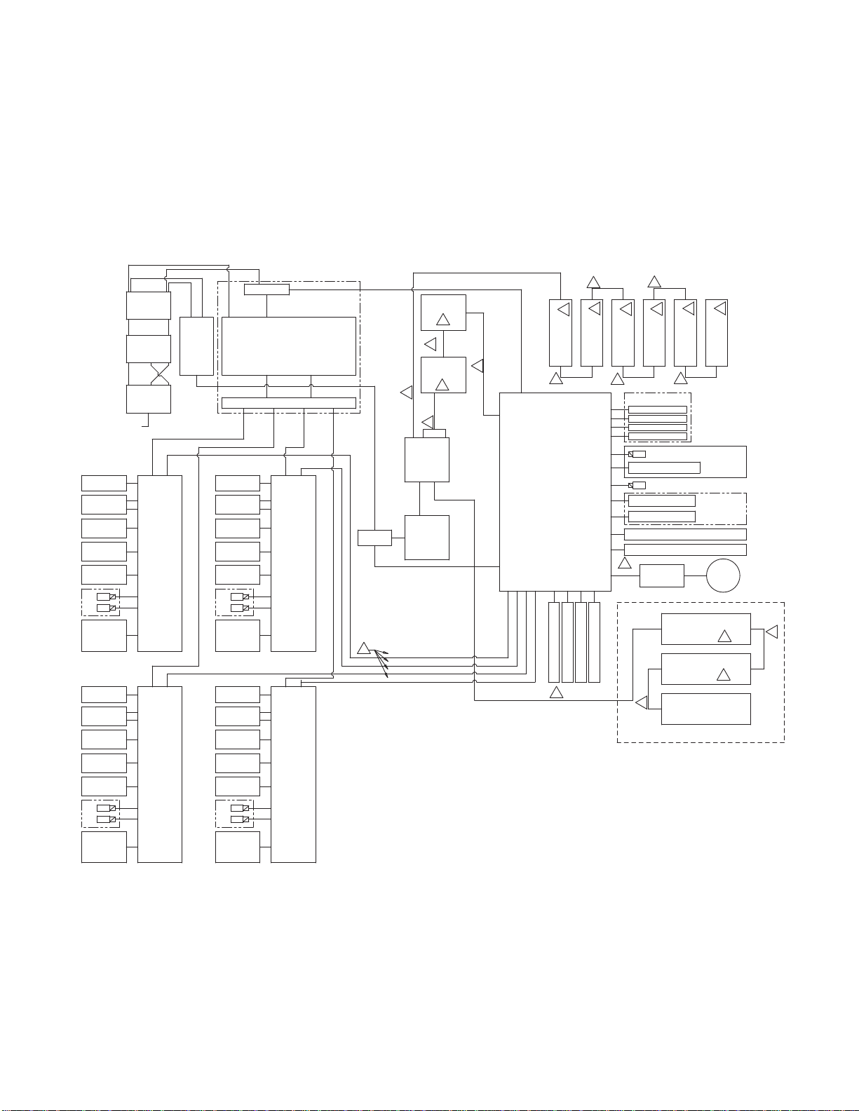
NOTE: The electrical schematic illustrates all possible
wiring expansions in a ProMix PD2K system. Some
components shown are not included with all systems.
NOTE: See Optional Cables and Modules, page 42,
for a list of cable options.
RELAY
(16U820)
16W159
BREAKOUT MODULE PUMP 2
BREAKOUT MODULE PUMP 4
POWER MODULE
(24R257)
16W159
16W159
(24N527)
(24N527)
SPLITTER
(16P243)
4
CABLE (16T659)
CABLE (16T659)
CABLE (16T659)
CABLE (16T659)
(24P658)
ENCODER AND MOTOR
(16P036, 16P037)
WIRE HARNESS
(24P684, 24P685)
PUMP INLET
TRANSDUCER
(16P289, 16P290)
PUMP OUTLET
TRANSDUCER
(16P289, 16P290)
PUMP V/P FOR
FLUID REG.
UP
DOWN
(16P812)
SOLENOID
MAC SERIES 46
FLOW SENSOR
(120278)
OR G3000 METER
(239716, 258718
16M510, 16M519)
(24P658)
ENCODER AND MOTOR
(16P036, 16P037)
WIRE HARNESS
(24P684, 24P685)
PUMP INLET
TRANSDUCER
(16P289, 16P290)
PUMP OUTLET
TRANSDUCER
(16P289, 16P290)
PUMP V/P FOR
FLUID REG.
UP
DOWN
(16P812)
SOLENOID
MAC SERIES 46
FLOW SENSOR
(120278)
OR G3000 METER
(239716, 258718
16M510, 16M519)
POWER IN
FAN
FAN
2 POSITION
SWITCH
(16U725)
CABLE
16T658
LINE FILTER
(16V446)
CABLE
16H078
TERMINAL BLOCK
(114095)
(24N527)
BREAKOUT MODULE PUMP 1
(24N527)
BREAKOUT MODULE PUMP 3
24V
POWER
SUPPLY
(16T660)
48V-10A POWER SUPPLY
TERMINAL BLOCKS WITH FUSES
16W159
FAN
(24P658)
ENCODER AND MOTOR
(16P036, 16P037)
WIRE HARNESS
(24P684, 24P685)
PUMP INLET
TRANSDUCER
(16P289, 16P290)
PUMP OUTLET
TRANSDUCER
(16P289, 16P290)
PUMP V/P FOR
FLUID REG.
UP
DOWN
(16P812)
SOLENOID
MAC SERIES 46
FLOW SENSOR
(120278)
OR G3000 METER
(239716, 258718
16M510, 16M519)
FAN
(24P658)
ENCODER AND MOTOR
(16P036, 16P037)
WIRE HARNESS
(24P684, 24P685)
PUMP INLET
TRANSDUCER
(16P289, 16P290)
PUMP OUTLET
TRANSDUCER
(16P289, 16P290)
PUMP V/P FOR
FLUID REG.
UP
DOWN
(16P812)
SOLENOID
MAC SERIES 46
FLOW SENSOR
(120278)
OR G3000 METER
(239716, 258718
16M510, 16M519)
Figure 15 Electrical Schematic, Sheet 1
INTEGRATION
GATEWAY
3
GATEWAY
(24R910)
CABLE (15V206)
2
CABLE
3
16T072
CAN
IS BOARD
(24M485)
CABLE
(16T280)
BARRIER
BOARD
(248192)
065161, 065159
5
CABLE
(121227)
AWI
5
(121227)
CABLE
3
(121001)
6
(24N935)
MODULE 1
COLOR CHANGE
CABLE
2
(15V206)
GCA
MODULE
EFCM
(24N913)
FLOW RATE ANALOG IN
FLOW RATE ANALOG IN
1
CABLE (16V429)
2
CABLE
(15V206)
6
(24N935)
MODULE 2
COLOR CHANGE
FLOW RATE ANALOG IN
FLOW RATE ANALOG IN
2
CABLE
(15V206)
6
6
6
(24N935)
(24N935)
MODULE 3
COLOR CHANGE
COLOR CHANGE
CABLE
2
(15V206)
GUN TRIGGER INPUTS
119159
119159
119159
119159
SOLENOID (121324)
PRESSURE SW (121323)
SOLVENT CUTOFF (121324)
SWITCH (120278)
SWITCH (120278)
SOLVENT METER (258718)
SAFETY INTERLOCK SWITCH
3
ADVANCED
CABLE
DISPLAY MODULE
(121003)
CABLE
1
(24N935)
MODULE 4
MODULE 5
CATALYST CHANGE
CABLE
2
(15V206)
(24E451)
COLOR CHANGE MODULE 7
(24R219)
COLOR CHANGE MODULE 8
(24R219)
(16V426)
BOOTH CONTROL (24M731)
HAZARDOUS LOCATION
NON-HAZARDOUS LOCATION
INTERFACES
MODULE 6
CATALYST CHANGE
GFB
SOLVENT
FLOW
INPUTS
LIGHT
TOWER
(15X472)
7
7
6
(24N935)
CABLE
1
(16V426)
36 333282B
Page 37

Electrical Sche
matics
SPLITTER
(16P243)
UNUSED
UNUSED
POWER
SUPPLY
(16T660)
L (BROWN)
N03 N03
2 POSITION
SWITCH
(16U725)
N04 N04
CABLE
(16T658)
L N
LINE
FILTER
(16V446)
L GRND N
CABLE
(16H078)
L N GRND
TERMINAL
BLOCK
(114095)
L N GRND
345
24V
2
1
UNUSED
GRND (GRN/YEL)
N (BLUE)
CABLE (16V429)
1
CONTINUED ON PAGE 3
2
3
CABLE
(15V206)
1 2 3 4 5
CAN IS BOARD
2
(NON IS)
(IS)
4
(24M485)
1 2 3 4 5
UNUSED
1 2 3 4 5
CABLE
(16T280)
1 2 3
1
2
3
BARRIER
BOARD
(248192)
13 A1(+) A2(-)
RELAY
14
N L GRND
48V-10A
POWER SUPPLY
(16U820)
+ -
+ - + - + - + -
F4
F3
F2
F1
+ - + - + - + -
DETAIL A, LOW PRESSURE
PUMPS (24M706, 24M714)
BREAKOUT MODULE
(24N527)
2
1 2 3 4 5 1 2 3 4
WIRE HARNESS
(24P684)
CABLE (121227)
16T072
1 2 3 4 5
1
3
UNUSED
UNUSED
RED WIRE (065161)
BLACK WIRE (065159)
1 2 3 4 5 1 2 3 4
(24R257)
POWER MODULE
3
DRAIN/FOIL
CABLE
1
2
3
4
5
P3
AWI
GATEWAY
(24R910)
1
2
3
P4
4
5
(121227)
3
1
2
3
P3
4
5
INTEGRATION
5
GFB INTERFACE
(121324)
SOLVENT CUTOFF (121324)
SOLVENT
METER
(258718)
PWR (RED)
SIG (WHITE)
COM (BLACK)
SHIELD/GRN
GROUND BAR
BREAKOUT MODULE PUMP 1 (24N527)
2
ENCODER/MOTOR
AND
WIRE HARNESS
PUMP 1
SEE DETAIL A OR B
3
1 2 3 4 5 1 2 3 4 5 1 2
TWISTED PAIR CABLE (16W159)
5
4
PUMP 1
PUMP 1
(16P289 OR 16P290)
INLET TRANSDUCER
(16P289 OR 16P290)
OUTLET TRANSDUCER
DETAIL B, HIGH PRESSURE
PUMPS (24M707, 24M715)
BREAKOUT MODULE
2
1 2 3 4 5 1 2 3 4
GATEWAY
5
6
1 2 3 4
(24N527)
WIRE HARNESS
(24P685)
1
2
3
P4
4
5
+12VDC
COM
UNUSED
UNUSED
+12VDC
COM
+12VDC
COM
UNUSED
PUMP 1
+24VDC
V/P FOR FLUID REG.
PUMP 1
MANIFOLD
UNUSED
UNUSED
UNUSED
CABLE
(121001)
3
1
7
3 4
5 6 7 8
COM
COM
+24VDC
UP
DOWN
PUMP 1
METER
PUMP 1
(EITHER, 239716,
258718,16M510,
(16P812 QTY 2)
MAC SERIES 46
3
5
4
3
10
2
1
1
2
3
8
4
5
1
2
3
4
5
6
5
7
8
9
10
11
12
25 PIN D-SUB CABLE
(16T659)
1 2 3 4
+48V
COM
PWR (RED)
SIG (WHITE)
COM (BLACK)
SHIELD/GRN
G3000
OR 16M519)
GRND
SCREW
DRAIN/FOIL
CONTINUED ON PAGE 3
GCA MODULE
(24N913)
12
4
252423222120191817161413121110 15987654321
BREAKOUT MODULE PUMP 2 (24N527)
3
2
FAN PUMP 1
+48V
COM
(24P658)
1 2 3 4 5 1 2 3 4
ENCODER/MOTOR
AND
WIRE HARNESS
PUMP 2
SEE DETAIL A OR B
1 2 3 4 5 1 2 3 4 5 1 2
TWISTED PAIR CABLE (16W159)
EFCM
252423222120191817161413121110 15987654321 252423222120191817161413121110 15987654321
5
4
PUMP 2
PUMP 2
(16P289 OR 16P290)
INLET TRANSDUCER
(16P289 OR 16P290)
OUTLET TRANSDUCER
6
1 2 3 4
PUMP 2
V/P FOR FLUID REG.
25 PIN
(16T659)
D-SUB CABLE
4
1
3 4
COM
COM
+24VDC
+24VDC
UP
DOWN
PUMP 2
PUMP 2
MANIFOLD
(16P812 QTY 2)
MAC SERIES 46
7
5 6 7 8
G3000
METER
PUMP 2
(EITHER, 239716,
258718,16M510,
OR 16M519)
PWR (RED)
SIG (WHITE)
COM (BLACK)
SCREW
88
1 2 3 4
+48V
COM
SHIELD/GRN
GRND
+48V
FAN PUMP 2
252423222120191817161413121110 15987654321
COM
(24P658)
DRAIN/FOIL
UNUSED UNUSED
UNUSED
UNUSED
UNUSED
UNUSED
UNUSED
UNUSED
UNUSED
UNUSED UNUSED
UNUSED
UNUSED UNUSED
POWER IN
UNUSED
UNUSED
DRAIN/FOIL
1 2 3 4 5 6 7 8 9
PUMP ENCODER AND MOTOR
MOTOR
MOUNTING
SCREW
UNUSED
UNUSED UNUSED
UNUSED
12
11
10
(16P037)
UNUSED
UNUSED
1 2 3 4 5 6 7 8 9
UNUSED
UNUSED UNUSED UNUSED
UNUSED
12
11
1 2
MOTOR
MOUNTING
SCREW
1 2 3 4 5 6 7 8 9
PUMP ENCODER AND MOTOR
10
10
(16P036)
1 2 3 4 5 6 7 8 9
UNUSED
10
Figure 16 Electrical Schematic, Sheet 2, Part 1
CONTINUED ON THE NEXT PAGE
333282B 37
Page 38

Electrical Sche
matics
GUN TRIGGER INPUTS
SIG
1
COM
2
SIG
3
COM
4
SIG
5
COM
6
6
7
SIG
8
COM
9
SIG
10
COM
11
SIG
12
1
2
3
4
5
6
7
7
8
9
10
11
12
1
2
3
9
4
5
COM
FLOW RATE ANALOG IN 1
FLOW RATE ANALOG COMMON 1
FLOW RATE ANALOG IN 2
FLOW RATE ANALOG COMMON 2
FLOW RATE ANALOG IN 3
FLOW RATE ANALOG COMMON 3
FLOW RATE ANALOG IN 4
FLOW RATE ANALOG COMMON 4
SIG
COM
SIG
COM
CABLE
(121003)
3
GCA MODULE
EFCM
(24N913)
34
252423222120191817161413121110 15987654321 252423222120191817161413121110 15987654321
119159
GFB PRESSURE SWITCH (121323)
SOLVENT FLOW SWITCH 1 (120278)
SOLVENT FLOW SWITCH 2 (120278)
SAFETY INTERLOCK SWITCH
1
ADVANCED
2
DISPLAY MODULE
3
4
(24E451)
5
1
2
3
4
5
LIGHT
TOWER
(15X472)
25 PIN
(16T659)
D-SUB CABLE
4
5
PUMP 3
(16P289 OR 16P290)
OUTLET TRANSDUCER
252423222120191817161413121110 15987654321
6
1 2 3 4
PUMP 3
V/P FOR FLUID REG.
3 4
COM
+24VDC
+24VDC
UP
PUMP 3
PUMP 3
MANIFOLD
(16P812 QTY 2)
MAC SERIES 46
COM
DOWN
7
5 6 7 8
G3000
METER
PUMP 3
(EITHER, 239716,
258718,16M510,
OR 16M519)
1
BREAKOUT MODULE PUMP 3 (24N527)
3
2
1 2 3 4 5 1 2 3 4 1 2 3 4 5 1 2 3 4
ENCODER/MOTOR
AND
WIRE HARNESS
PUMP 3
SEE DETAIL A OR B
4
1 2 3 4 5 1 2 3 4 5 1 2
PUMP 3
(16P289 OR 16P290)
INLET TRANSDUCER
TWISTED PAIR CABLE (16W159)
Figure 17 Electrical Schematic, Sheet 2, Part 2
CONTI
NUED ON THE NEXT PAGE
PWR (RED)
SIG (WHITE)
COM (BLACK)
SCREW
25 PIN D-SUB CABLE
8
1 2 3 4
+48V
+48V
COM
SHIELD/GRN
FAN PUMP 3
GRND
(16T659)
COM
(24P658)
4
2
ENCODER/MOTOR
AND
WIRE HARNESS
PUMP 4
SEE DETAIL A OR B
5
PUMP 4
(16P289 OR 16P290)
OUTLET TRANSDUCER
252423222120191817161413121110 15987654321
6
1 2 3 4
PUMP 4
V/P FOR FLUID REG.
3 4
COM
+24VDC
+24VDC
UP
PUMP 4
PUMP 4
MANIFOLD
(16P812 QTY 2)
MAC SERIES 46
7
COM
DOWN
1
BREAKOUT MODULE PUMP 4 (24N527)
3
4
1 2 3 4 5 1 2 3 4 5 1 2 1 2 3 4
PUMP 4
(16P289 OR 16P290)
INLET TRANSDUCER
TWISTED PAIR CABLE (16W159)
5 6 7 8
PWR (RED)
SIG (WHITE)
G3000
METER
PUMP 4
(EITHER, 239716,
258718,16M510,
OR 16M519)
+48V
COM (BLACK)
SHIELD/GRN
GRND
SCREW
8
COM
+48V
FAN PUMP 4
COM
(24P658)
38 333282B
Page 39

Electrical Sche
matics
FLUSH
COLOR 1
COLOR 2
COLOR 3
COLOR 4
COLOR 5
COLOR 6
COLOR 7
COLOR 8
*FLUSH
COLOR 9
COLOR 10
COLOR 11
COLOR 12
COLOR 13
COLOR 14
COLOR 15
COLOR 16
CABLE (15V206)
2
MANIFOLD
MANIFOLD
+12VDC
+12VDC
+12VDC
+12VDC
+12VDC
+12VDC
+12VDC
COM
+12VDC
COM
+12VDC
COM
+12VDC
+12VDC
+12VDC
+12VDC
+12VDC
+12VDC
+12VDC
+12VDC
+12VDC
COM
COM
COM
COM
COM
COM
COM
COM
COM
COM
COM
COM
COM
COM
COM
1
2
3
4
5
6
1
2
3
4
5
6
1
2
3
4
5
6
2
1
2
3
4
5
6
1
2
3
4
5
6
1
2
3
4
5
6
FROM CAN IS BOARD (24M485) ON PAGE 2
2
345
1
COLOR
CHANGE
MODULE 1
(COLORS
6
1 THRU 8)
J8
J15
J14
1
2
6
J16
J10
345
COM
5
+12VDC
4
COM
J9
3
+12VDC
2
COM
1
+12VDC
6
COM
5
+12VDC
4
COM
3
+12VDC
2
COM
1
+12VDC
6
COM
5
+12VDC
4
COM
3
+12VDC
2
COM
1
+12VDC
CABLE
J8
J15
J14
2
345
1
COLOR
CHANGE
MODULE 2
(COLORS
9 THRU 16)
6
2
345
1
J16
J10
J9
(15V206)
6
5
4
3
2
1
6
5
4
3
2
1
6
5
4
3
2
1
COM
+12VDC
COM
+12VDC
COM
+12VDC
COM
+12VDC
COM
+12VDC
COM
+12VDC
COM
+12VDC
COM
+12VDC
COM
+12VDC
MANIFOLD
MANIFOLD
DUMP
COLOR 1
COLOR 2
COLOR 3
COLOR 4
COLOR 5
COLOR 6
COLOR 7
COLOR 8
DUMP*
COLOR 9
COLOR 10
COLOR 11
COLOR 12
COLOR 13
COLOR 14
COLOR 15
COLOR 16
FLUSH
CATALYST 1
CATALYST 2
CATALYST 3
CATALYST 4
FROM CAN IS BOARD (24M485) ON PAGE 2
MANIFOLD
+12VDC
COM
+12VDC
COM
+12VDC
COM
+12VDC
COM
+12VDC
COM
UNUSED
UNUSED
UNUSED
UNUSED
UNUSED
UNUSED
UNUSED
UNUSED
1
2
3
4
5
6
1
2
3
4
5
6
1
2
3
4
5
6
CATALYST
CHANGE
MODULE 5
(CATALYST
1 THRU 4)
J8
J15
J14
2
1
6
345
J16
J10
COM
+12VDC
COM
+12VDC
COM
+12VDC
COM
+12VDC
COM
+12VDC
UNUSED
UNUSED
UNUSED
UNUSED
UNUSED
UNUSED
UNUSED
UNUSED
MANIFOLD
DUMP
CATALYST 1
CATALYST 2
CATALYST 3
CATALYST 4
6
5
4
J9
3
2
1
6
5
4
3
2
1
6
5
4
3
2
1
2
*FLUSH
COLOR 17
COLOR 18
COLOR 19
COLOR 20
COLOR 21
COLOR 22
COLOR 23
COLOR 24
MANIFOLD
+12VDC
COM
+12VDC
COM
+12VDC
COM
+12VDC
COM
+12VDC
COM
+12VDC
COM
+12VDC
COM
+12VDC
COM
+12VDC
COM
1
2
3
4
5
6
1
2
3
4
5
6
1
2
3
4
5
6
CABLE
J8
J15
J14
2
345
1
COLOR
CHANGE
MODULE 3
(COLORS
17 THRU 24)
6
2
4
5
3
J9
J16
J10
1
(15V206)
6
5
4
3
2
1
6
5
4
3
2
1
6
5
4
3
2
1
COM
+12VDC
COM
+12VDC
COM
+12VDC
COM
+12VDC
COM
+12VDC
COM
+12VDC
COM
+12VDC
COM
+12VDC
COM
+12VDC
Figure 18 Electrical Schematic, Sheet 3
* May be unused in some configurations.
CONTINUED ON THE NEXT PAGE
MANIFOLD
DUMP*
COLOR 17
COLOR 18
COLOR 19
COLOR 20
COLOR 21
COLOR 22
COLOR 23
COLOR 24
2
COLOR 25
COLOR 26
COLOR 27
COLOR 28
COLOR 29
COLOR 30
CABLE (15V206)
*FLUSH
MANIFOLD
+12VDC
COM
+12VDC
COM
+12VDC
COM
+12VDC
COM
+12VDC
COM
+12VDC
COM
+12VDC
COM
UNUSED
UNUSED
UNUSED
UNUSED
22
1
2
3
4
5
6
1
2
3
4
5
6
1
2
3
4
5
6
CABLE
2
1
COLOR
CHANGE
MODULE 4
(COLORS
25 THRU 32)
J8
J15
J14
2
1
345
6
345
J16
J10
J9
(15V206)
6
5
4
3
2
1
6
5
4
3
2
1
6
5
4
3
2
1
COM
+12VDC
COM
+12VDC
COM
+12VDC
COM
+12VDC
COM
+12VDC
COM
+12VDC
COM
+12VDC
UNUSED
UNUSED
UNUSED
UNUSED
MANIFOLD
DUMP*
COLOR 25
COLOR 26
COLOR 27
COLOR 28
COLOR 29
COLOR 30
333282B 39
Page 40

Electrical Sche
matics
CATALYST 3
CATALYST 4
CATALYST 1
CATALYST 2
FLUSH
FLUSH
MANIFOLD
MANIFOLD
+12VDC
COM
+12VDC
COM
+12VDC
COM
UNUSED
UNUSED
UNUSED
UNUSED
UNUSED
UNUSED
UNUSED
UNUSED
UNUSED
UNUSED
UNUSED
UNUSED
+12VDC
COM
+12VDC
COM
+12VDC
COM
UNUSED
UNUSED
UNUSED
UNUSED
UNUSED
UNUSED
UNUSED
UNUSED
UNUSED
UNUSED
UNUSED
UNUSED
1
2
3
4
5
6
1
2
3
4
5
6
1
2
3
4
5
6
22
1
2
3
4
5
6
1
2
3
4
5
6
1
2
3
4
5
6
CATALYST
CHANGE
MODULE 6
(CATALYST
3 THRU 4)
J8
J15
J14
2
1
CABLE
5
4
CATALYST
CHANGE
MODULE 5
(CATALYST
1 THRU 2)
J8
J15
J14
2
1
6
345
2
3
6
345
J9
J16
J10
1
J9
J16
J10
6
5
4
3
2
1
6
5
4
3
2
1
6
5
4
3
2
1
(15V206)
6
5
4
3
2
1
6
5
4
3
2
1
6
5
4
3
2
1
COM
+12VDC
COM
+12VDC
COM
+12VDC
UNUSED
UNUSED
UNUSED
UNUSED
UNUSED
UNUSED
UNUSED
UNUSED
UNUSED
UNUSED
UNUSED
UNUSED
COM
+12VDC
COM
+12VDC
COM
+12VDC
UNUSED
UNUSED
UNUSED
UNUSED
UNUSED
UNUSED
UNUSED
UNUSED
UNUSED
UNUSED
UNUSED
UNUSED
MANIFOLD
DUMP
CATALYST 3
CATALYST 4
MANIFOLD
DUMP
CATALYST 1
CATALYST 2
Figure 19 Electrical Schematic, Sheet 3, Alternate
Configuration for Catalyst Change Control
INUED ON THE NEXT PAGE
CONT
2
CABLE
2
345
1
COLOR
CHANGE
MODULE 4
(COLORS
25 THRU 32)
(15V206)
40 333282B
Page 41

FROM CAN IS BOARD (24M485) ON PAGE 2
Electrical Sche
matics
COLOR FLUSH
COLOR 1
COLOR 2
COLOR 3
COLOR 4
COLOR 5
COLOR 6
COLOR 7
COLOR 8
COLOR 13
COLOR 14
COLOR 15
COLOR 16
COLOR 17
COLOR 18
COLOR 19
COLOR 20
COLOR 21
MANIFOLD
MANIFOLD
+12VDC
COM
+12VDC
COM
+12VDC
COM
+12VDC
COM
+12VDC
COM
+12VDC
COM
+12VDC
COM
+12VDC
COM
+12VDC
COM
+12VDC
COM
+12VDC
COM
+12VDC
COM
+12VDC
COM
+12VDC
COM
+12VDC
COM
+12VDC
COM
+12VDC
COM
+12VDC
COM
1
2
3
4
J8
5
6
1
2
3
J15
4
5
6
1
2
3
4
J14
5
6
1
1
2
3
J8
4
5
6
1
2
3
J15
4
5
6
1
2
3
J14
4
5
6
2
345
1
COLOR
CHANGE
MODULE 7
(COLORS
33 THRU 40)
7
2
345
1
CABLE
2
345
1
COLOR
CHANGE
MODULE 8
(COLORS
41 THRU 48)
7
5
2
3
4
J16
J10
J9
J16
J10
J9
(16V426)
1
NON-HAZARDOUS LOCATION
HAZARDOUS LOCATION
COM
+12VDC
COM
+12VDC
COM
+12VDC
COM
+12VDC
COM
+12VDC
COM
+12VDC
COM
+12VDC
COM
+12VDC
COM
+12VDC
COM
+12VDC
COM
+12VDC
COM
+12VDC
COM
+12VDC
COM
+12VDC
COM
+12VDC
MANIFOLD
MANIFOLD
6
5
4
3
2
1
6
COM
5
+12VDC
4
COM
3
+12VDC
2
COM
1
+12VDC
6
5
4
3
2
1
6
5
4
3
2
1
6
5
4
3
2
1
6
5
4
3
2
1
CATALYST FLUSH
CATALYST 1
CATALYST 2
CATALYST 3
CATALYST 4
COLOR 9
COLOR 10
COLOR 11
COLOR 12
COLOR 22
COLOR 23
COLOR 24
COLOR 25
COLOR 26
COLOR 27
COLOR 28
COLOR 29
COLOR 30
1
BOOTH CONTROL
Figure 20 Electrical Schematic, Sheet 3, Hazardous
Location
333282B
CABLE
5
4
(24M731)
(16V426)
2
3
1
41
Page 42

Electrical Sche
matics
Optional Cabl
NOTE: Thetotallengthofallcableusedinthesystemmustnotexceed150ft(45m). See the
Electrical Schematics, page 36.
M12 CAN Cables, for Hazardous Locations
NOTE: The total length of cable used in the
hazardous location must not exceed 120 ft (36 m).
Cable Part N
16V423
16V424
16V425
16V426
16V427
16V428
16V429
16V430
M12 CAN Ca
15U531
15U532
15V205
15V206
15V207
15V208
15U533
15V213
CAN Cables, for Non-Hazardous
Part No.
Cable
125306
123422
121000
121227
121001
121002
121003
120952
121201
121004
121228
es and Modules
o.
Location
Locations Only
Length ft (m
2.0 (0.6)
3.0 (1.0)
6.0 (2.0)
10.0 (3.0)
15.0 (5.0)
25.0 (8.0)
50.0 (16.
100.0 (32
bles, for Non-Hazardous
sOnly
2.0 (0.6)
3.0 (1.0)
6.0 (2.0)
10.0 (3.0)
15.0 (5.0)
25.0 (8.0)
50.0 (16.0)
100.0 (32.0)
Lengt
1.0 (0
1.3 (0
1.6 (
2.0 (
3.0 (
5.0 (
10.0
13.
20.
25.
50.
0)
.0)
hft(m)
.3)
.4)
0.5)
0.6)
1.0)
1.5)
(3.0)
0 (4.0)
0 (6.0)
0 (8.0)
0(15.0)
25 Pin D-SUB Cables, for Non-Hazardous
Locations Only
16T659
)
16V659
Alternates f
for Non-Haza
Module Part
CGMDN0*, DeviceNet CGMPB0*, Profibus
CGMEP0*, Ethernet IP CGMPN0*, Profinet
* You must purchase Map Token Kit 17C087 for
usewiththesekits.
Alternate
by Part Num
Non-Hazar
Module Par
24T557 2 color/2
24T558 4 color/4
24T559 6 color/6
24T560 8 color/
Alternates for Color Change Modules by Part
Number (Factory Configuration), for Hazardous
24T571 2 color/2 catalyst
24T572 4 color/2 catalyst
24T573 6 color/2 catalyst
24T574 8 color/2 catalyst, 13–24
24T774 12 color/2 catalyst
24T775 4 color/4 catalyst
24T776 6 color/4 catalyst
24T777 8 color/4 catalyst
24T778 12 color/4 catalyst, 13–30
24T779 13–18 color
or Communication Module 24R910,
No.
s for Color Change Modules
ber (Factory Configuration), for
dous Locations Only, see page 61
tNo.
Locations Only, see page 62
2.5 (0.8)
6.0 (1.8)
rdous Locations Only
Module Part
Descripti
color
color
on
catalyst
catalyst
catalyst
8 catalyst
No.
2
4
333282B
Page 43

Repair
• To avoid electric shock, turn off power at the
main circuit breaker before opening the control
module.
• All electrical wiring must be done by a qualified
electrician and comply with all local codes and
regulations.
• Do not substitute or modify system components
as this may impair intrinsic safety.
NOTICE
To avoid damaging the circuit boards, wear Part
No. 112190 grounding strap on your wrist and
ground appropriately.
Repair
Figure 21 Remove Retainer
3. Using the other end of the tool (114), screw it all
the way onto the valve (3). Pull the valve from
the manifold.
To avoid electrical component damage, remove all
system power before plugging any connectors.
Replace a Color Valve
Use the following procedure to replace a valve,
whether the valve is part of the color stacks near the
pump or part of the remote color stacks.
1. Flush and relieve pressure as described in your
PD2K operation manual.
2. Engage the pins of the tool (114) with the notches
in the retainer (5) and unscrew the retainer.
Figure 22 Remove the Valve
NOTE: See manual 332454 to repair the valve.
4. Install the valve in the reverse order of
disassembly. Be sure all o-rings are in place
and lubricated, and that the valve is seated
completely in the manifold.
5. Return the system to service.
333282B 43
Page 44

Repair
Replace a Sole
1. Remove electrical power from the system.
2. Remove air supply pressure from the system.
3. Remove the color change module cover (304).
4. Disconnect the two solenoid wires from
the color change board (302). See the
color change board wiring diagrams in the
Electrical Schematics, page 36.
5. Remove the solenoid (310) from the manifold
(309).
6. Install the new solenoid.
7. Connect the two solenoid wires to the
color change board (302). See the color
change board wiring diagrams in the
Electrical Schematics, page 36.
8. Reinstall the cover.
noid
Replace the Co
lor Change Board
Fuse
NOTE: Replacing the fuse with a non-Graco fuse
voids the IS system safety approval.
Fuse Part No. Description
F1 123690 Fuse; 125 mA,
intrinsically safe
1. Remove electrical power from the system.
2. Remove the color change module cover (304).
3. Locate fuse F1 (302a) on the color change board.
Pull the fuse away from the board.
4. Install the new fuse.
5. Reinstall the cover. Restore electrical power to
the system.
4
4
333282B
Page 45

Repair
Replace the Co
lor Change Board
NOTICE
To avoid damaging the circuit boards, wear Part
No. 112190 grounding strap on your wrist and
ground appropriately.
To avoid electrical component damage, remove all
system power before plugging any connectors.
1. Remove electrical power from the system.
2. Remove the col
3. Note where each cable is connected, then
disconnect all cables from the color change
board connectors.
4. Remove the seven mounting screws (303) and
the board (302).
5. Install the new board. Reinstall the screws.
6. Reconnect the cables to the proper
connectors, as noted in step 3. See
Electrical Schematics, page 36.
7. Reinstall the cover (304). Restore electrical
power to the system.
or change module cover (304).
re 23 Control Module Repair (Non-IS Module
Figu
n)
Show
333282B 45
Page 46

Parts
Parts
Non-IS Color Change Kits
Detail of Back Pressure Regulator (High Pressure Outlet Stack only)
46 333282B
Page 47

Parts
Ref.
No.
101 24U237
102
103 100157
104 103195
105 100016
106 100015 NUT, hex; 1/
107 24N346
108
109 15V206
110 16V819
111 24U236
114
Part
No.
◆
◆
◆
Description
BRACKET, mounting
KIT, manifold, valve
SCREW, cap, h
1/4–20 x 0.37
SCREW, cap, hex head;
1/4–20 x 4.0 in. (101 mm)
WASHER, lock; 1/4
HOSE, fluid; 1/4 npsm (fbe);
2.5 ft (0.76 m); ptfe
KIT, module, control 1
CABLE, CA
10 ft (3.0
GROMMET, cable
TOOL, repair, valve (not
shown)
TOOL, installation, valve (not
shown)
5m)
ex head;
5in.(10mm)
4–20
N; 5–pin female;
Qty
1
2
4
4
4
4
2
1
1
1
1
Ref.
No.
115 598095
120 222200
121 113070 NIPPLE; 3/8 npt x 1/4 npt; sst;
122 110290
123 112564
Part
No.
Description
TUBE; nylon; 5/32 in. (4 mm)
OD
REGULATOR, back pressure;
used on high pressure kits
only (see detail drawing); see
manual 307892
used on high pressure kits
only (see detail drawing)
TEE; 1/4 npt(f); sst; used on
high pressure kits only (see
detail drawing)
GAUGE, pressure, fluid; used
on high pressure kits only (see
detail drawing)
Qty
◆
1
2
1
1
◆ See the following tables for the part number used
in your color change kit.
Low Pressure Non-IS Kits
Kit No. Kit Description
Standard Valve
Manifold Kits
(102) [see
Low Pressure
Valve Manifold
Kits, page 53 for
Control Module
Kit (108) [see
Non-IS Color
Change Control
Modules, page
64 for parts]
all available
kits]
Low Pressure Non-Circulating Color Change Kits
24R915 2 color or 2
24T458 24T557 24U239
catalyst
24R916 4 color or 4
24T460 24T558 24U239
catalyst
24R917 6 color 24T462 24T559 24U239
24R918 8 color 24T464 24T560 24U239
Low Pressure Circulating Color Change Kits
24R919 2 color 24T488 24T557 24U239
24R920 4 color 24T490 24T558 24U239
24R921 6 color 24T492 24T559 24U239
Tool (114)
Tube Length
(115)
60 ft (18.3 m)
120 ft (36.6 m)
210 ft (64.05 m)
360 ft (109.8 m)
60 ft (18.3 m)
120 ft (36.6 m)
210 ft (64.05 m)
24R922 8 color 24T494 24T560 24U239
333282B
360 ft (109.8 m)
47
Page 48

Parts
High Pressure Non-IS Kits
Kit No. Kit Description
High Pressure Non-Circulating Color Change Kits
24R959 2 color or 2
catalyst
24R960 4 color or 4
catalyst
24R961 6 color 24T652 24T559 24U240
24R962 8 color 24T654 24T560 24U240
High Pre
24T579 2 catalyst 24U182 24T557 24U240
24T580 4 catal
24R963 2 color 24T678 24T557 24U240
ssure Acid Compatible Non-Circulating Catalyst Change Kits
yst
Standard Valve
Manifold Kits
(102) [see
High Pressure
Valve Manifold
Kits, page 58 for
all available
kits]
24T648 24T557 24U240
24T650 24T558 24U240
24U183 24T558 24U240
High P
ressure Circulating Color Change Kits
Control Module
Kit (108) [see
Non-IS Color
Change Control
Modules, page
64 for parts]
Tool (114)
Tube Length
(115)
60 ft (18.3 m
120 ft (36.6 m)
210 ft (64.05 m)
360 ft (109.8 m)
60 ft (18.3 m)
120 ft (36.6 m)
60 ft (18.3 m)
)
64
24R9
24R965 6 color 24T682 24T559 24U240
24R966 8 color 24T684 24T560 24U240
4col
or
24T6
80
24T5
58
24U2
40
120 ft (36.6 m)
ft (64.05 m)
210
360 ft (109.8 m)
48 333282B
Page 49

Notes
Parts
333282B 49
Page 50

Parts
IS Color Chang
eKits
Ref.
No.
101
103 24V351
104 24N346
105
10
107 16Y954
108 100015 NUT, hex 4
109
Part No. Description
◆
16W564 Low Pressure
16W563 High Pressure
◆
6
104429 Low Pressure
113469 High Pressure
KIT, manifold, valve; . See
Valve Manifold Kits, page
53 for available kits.
MANIFOLD, mix, remote
HOSE, coupled, 2.5 ft.
HOSE
T, module, control
KI
BRACKET, manifold
CREW, cap, hex
S
, static mixer
Qty
2
1
2
1
1
2
4
Ref.
No.
110
111
112 223
113 100016
114 16V429
Part No. Description
TOOL, repair, color change
valve, not shown
24U236 Low Pressure
24R124 High Pressure
, installation, color
TOOL
ge valve, not shown
chan
24U239 Low Pressure
24U240 High Pressure
547
WIRE,assembly,25ft.
WASHER, lock
CABLE, CAN, 50 ft (15.2 m);
not shown
Qty
1
1
2
4
1
◆ See the following tables for the part number used
in your color change kit.
50 333282B
Page 51

Low Pressure IS Kits
Parts
Kit No. Kit Description
Low Pressure Non-Circulating Color Change Kits
24V157 1 color and 1 catalyst
24V158 2 colors and 1 catalyst 24T458, 24T457 24T571
24V159 4 colors and 1 catalyst 24T460, 24T457 24T572
24V160 6 colors an
24V161 8 colors and 1 catalyst 24T464, 24T457 24T574
24V162 12 colors and 1 catalyst 24T468, 24T369 24T774
24V331 2 colors a
24V332 4 colors and 2 catalysts 24T460, 24T458 24T572
24V333 6 colors
24V334 8 colors and 2 catalysts 24T464, 24T458 24T574
24V335 12 colors and 2 catalysts 24T468, 24T458 24T774
3
24V34
24V344 6 colors and 4 catalysts 24T462, 24T460 24T776
4colo
d 1 catalyst
nd 2 catalysts
and 2 catalysts
rs and 4 catalysts
Standard Valve Man-
ifold Kits (101) [see
Low Pressure Valve
Manifold Kits, page 53 for
all available kits]
24T457 (2)
24T462, 24
24T458 (2)
24T462,
24T460 (2)
T457
24T458
Control Module
Kit (106) [see
IS Color Change Control
Modules, page 66 for
parts]
24T571
24T573
24T571
24T573
24T77
5
45
24V3
24V346 12 colors and 4 catalysts 24T468, 24T460 24T778
24V166 1 color and 1 catalyst
24V167 2 colors and 1 catalyst 24T488, 24T487 24T571
24V308 4 colors and 1 catalyst 24T490, 24T487 24T572
V309
24
24V326 8 colors and 1 catalyst 24T494, 24T487 24T574
24V327 12 colors and 1 catalyst 24T498, 24T487 24T774
4V336
2
24V337 4 colors and 2 catalysts 24T490, 24T488 24T572
24V338 6 colors and 2 catalysts 24T492, 24T488 24T573
24V339 8 colors and 2 catalysts 24T494, 24T488 24T574
24V340 12 colors and 2 catalysts 24T498, 24T488 24T774
24V347 4 colors and 4 catalysts
24V348 6 colors and 4 catalysts 24T492, 24T490 24T776
24V349 8 colors and 4 catalysts 24T494, 24T490 24T777
ors and 4 catalysts
8col
Low Pressure Circulating Color Change Kits
olors and 1 catalyst
6c
colors and 2 catalysts
2
64, 24T460
24T4
487 (2)
24T
T492, 24T487
24
24T488 (2)
24T490 (2)
77
24T7
24T571
T573
24
4T571
2
24T775
24V350 12 colors and 4 catalysts 24T498, 24T490 24T778
333282B 51
Page 52

Parts
High Pressure IS Kits
Kit No. Kit Description
High Pressure Non-Circulating Color Change Kits
24V359 1 color and 1 catalyst
24V360 2 colors and 1 catalyst 24T648, 24T647 24T571
24V361 4 colors and 1 catalyst 24T650, 24T647 24T572
24V362 6 colors an
24V363 8 colors and 1 catalyst 24T654, 24T647 24T574
24V364 12 colors and 1 catalyst 24T658, 24T647 24T774
24V381 2 colors a
24V382 4 colors and 2 catalysts 24T650, 24T648 24T572
24V383 6 colors
24V384 8 colors and 2 catalysts 24T654, 24T648 24T574
24V385 12 colors and 2 catalysts 24T658, 24T648 24T774
6
24V39
24V397 6 colors and 4 catalysts 24T652, 24T650 24T776
4colo
d 1 catalyst
nd 2 catalysts
and 2 catalysts
rs and 4 catalysts
Standard Valve Manifold Kits (101) [see
Low Pressure Valve
Manifold Kits, page 53 for
all available kits]
24T647 (2)
24T652, 24
24T648 (2)
24T652,
24T650 (2)
T647
24T648
Control Module
Kit (106) [see
IS Color Change Control
Modules, page 66 for
parts]
24T571
24T573
24T571
24T573
24T77
5
98
24V3
24V399 12 colors and 4 catalysts 24T658, 24T650 24T778
24V369 1 color and 1 catalyst
24V370 2 colors and 1 catalyst 24T678, 24T677 24T571
24V371 4 colors and 1 catalyst 24T680, 24T677 24T572
V372
24
24V373 8 colors and 1 catalyst 24T684, 24T677 24T574
24V374 12 colors and 1 catalyst 24T688, 24T677 24T774
4V389
2
24V390 4 colors and 2 catalysts 24T680, 24T678 24T572
24V391 6 colors and 2 catalysts 24T682, 24T678 24T573
24V392 8 colors and 2 catalysts 24T684, 24T678 24T574
24V393 12 colors and 2 catalysts 24T688, 24T678 24T774
24V402 4 colors and 4 catalysts
24V403 6 colors and 4 catalysts 24T682, 24T680 24T776
24V404 8 colors and 4 catalysts 24T684, 24T680 24T777
ors and 4 catalysts
8col
High Pressure Circulating Color Change Kits
olors and 1 catalyst
6c
colors and 2 catalysts
2
54, 24T650
24T6
677(2)
24T
T682, 24T677
24
24T678 (2)
24T680 (2)
77
24T7
24T571
T573
24
4T571
2
24T775
24V405 12 colors and 4 catalysts 24T688, 24T680 24T778
52 333282B
Page 53
Parts
Valve Manifol
The low pressure and high pressure valve manifold
kits listed in this section are used in both the Non-IS
and IS color valve stacks.
dKits
Low Pressure Valve Manifold Kits
Non-Circulating Valve Manifold Kits
Kit No.
24T457 A 2 valves
24T458 A 3 valves
24T459 A 4 valves
24T460 A 5 valves
24T461 A 6 valves
24T462 A 7 valves
24T463 A 8 valves
24T464 A 9 valves
24T465 A 10 valve
24T466 A 11 valves
Series
Kit Description
s
Circulating Valve Manifold Kits
Kit No.
24T487 A 2 valves
24T488 A 3 valves
24T489 A 4 valves
24T490 A 5 valves
24T491 A 6 valves
24T492 A 7 valves
24T493 A 8 valves
24T494 A 9 valves
24T495 A 10 valve
24T496 A 11 valves
Series
Kit Description
s
24T467 A 12 valves
8
24T46
24T469 A 14 valves
24T470 A 15 valves
71
24T4
24T472 A 17 valves
24T473 A 18 valves
474
24T
24T475 A 20 valves
24T476 A 21 valves
T477
24
24T478 A 23 valves
24T479 A 24 valves
4T480
2
24T481 A 26 valves
24T482 A 27 valves
24T483 A 28 valves
A13val
A16va
A19v
A22
A2
ves
lves
alves
valves
5valves
24T497 A 12 valves
8
24T49
24T499 A 14 valves
24T500 A 15 valves
01
24T5
24T502 A 17 valves
24T503 A 18 valves
504
24T
24T505 A 20 valves
24T506 A 21 valves
T507
24
24T508 A 23 valves
24T509 A 24 valves
4T510
2
24T511 A 26 valves
24T512 A 27 valves
24T513 A 28 valves
A13val
A16va
A19v
A22
A2
ves
lves
alves
valves
5valves
24T484 A 29 valves
24T485 A 30 valves
24T486 A 31 valves
24T514 A 29 valves
24T515 A 30 valves
24T516 A 31 valves
333282B 53
Page 54

Parts
Valve Manifold Kit Parts
54 333282B
Page 55

Parts
Ref.
No.
1 16P259
2
3
4 24R051
5
6 111457
7
8 24T522
9 157974
10 104092
11 100179 NUT, he
Low Pre
Kit No.
24T457
24T45
Part No. Description
MANIFOLD
111450
24T441
24T442
16N256 RETAINER, nut
24T521
O-RING; chemically resistant
VALVE, for non-circulating
kits; includes item 2
VALVE, for circulating kits;
includes item 2
PLUG, cc valve
O-RING; ptfe
PLATE, outlet, manifold
PLATE, en
WASHER, plain
SCREW, cap, socket head;
10–24 x 0.625 in. (16 mm)
d, manifold
x; 10–24
Qty
★
Ref.
No.
12 104893
13 24T523
14 111328
15 24T525
16 24T524
17 111504
18 557716
19 104644
★ See the following tables to determine the quantity
of each part in your valve manifold kit.
ssure Non-Circulating Valve Manifold Kit Part Quantities
Reference Numbers
123
1
2
8
5
4
2202211333203120
43143113443301
7
6
8 101213141516171819
24T459 244043113
Part No. Description
O-RING; ptfe
FITTING, fluid; 7/16–20 x 1/4
npt(m)
CONNECTOR, t
10–32(m) x 5/
mm) OD tube
ROD, connecting; 3 in. (76
mm)
ROD, connecting; 1.5 in. (38
mm)
O-RING; chemically resistant
PLUG; 7/16–20
PLUG, screw; 10–32 x 0.156
in. (4 mm)
55
3
4
Qty
ube;
32 in. (4
★
5
2
0140
24T460 3 6
61
24T4
24T462
24T463
464
24T
24T465
24T466
4T467
2
24T468
24T469
24T470
24T471
24T472
24T473
24T474
24T475
3
4
4
5
5
6
6
7
7
8
8
9
9
10
10
5
16411366
66064113
7
8
18
8808
5
11388
5
11399860180
77
5
331
7
2
633160
7
60192
10 9 1 10 6 1 1 3 10 10 9 6 3 1 11 2
10100106113111110631100
12 11 1 12
212
1
01
7
113121211901132
7
2
11313131
2
901120
14131148113141413931152
14140148113151514931140
16 15 1 16 9 1 1 3 16 16 15 12 0 1 17 2
16 16 0 16 9 1 1 3 17 17 16 12 0 1 16 0
18 17 1 18 10 1 1 3 18 18 17 12 3 1 19 2
18 18 0 18 10 1 1 3 19 19 18 12 3 1 18 0
20 19 1 20 11 1 1 3 20 20 19 15 0 1 21 2
20 20 0 20 11 1 1 3 21 21 20 15 0 1 20 0
333282B 55
Page 56

Parts
Kit No.
24T476
24T477
24T478
24T479
24T480
24T481
24T482
24T483
24T484
24T485
24T486
Reference Numbers
5
123
11
22 21 1 22 12 1 1 3 22 22 21 15 3 1 23 2
11
22 22 0 22 12 1 1 3 23 23 22 15 3 1 22 0
12
24 23 1 24 13 1 1 3 24 24 23 18 0 1 25 2
12
24 24 0 24 13 1 1 3 25 25 24 18 0 1 24 0
13
26 25 1 26 14 1 1 3 26 26 25 18 3 1 27 2
13
26 26 0 26 14 1 1 3 27 27 26 18 3 1 26 0
14
28 27 1 28 15 1 1 3 28 28 27 21 0 1 29 2
14
28 28 0 28 15 1 1 3 29 29 28 21 0 1 28 0
15
30 29 1 30 16 1 1 3 30 30 29 21 3 1 31 2
15
30 30 0 30 16 1 1 3 31 31 30 21 3 1 30 0
16
32 31 1 32 17 1 1 3 32 32 31 24 0 1 33 2
4
7
6
8 101213141516171819
56 333282B
Page 57

Low Pressure Circulating Valve Manifold Kit Part Quantities
Parts
Kit No.
24T487
24T488
5
123
1
22022113
2
43143113
4
6
Reference Numbers
7
8 101213141516171819
55
77
203100
330122
24T489 244043113994
24T490 3 6
24T491
24T492
24T493
24T494
24T495
24T496
24T497
24T498
24T499
24T500
24T501
24T502
24T503
24T50
24T505
24T506
07
24T5
24T508
24T509
T510
24
24T511
24T512
4T513
2
24T514
24T515
24T516
4
3
4
4
5
5
6
6
7
7
8
8
9
9
10
10
11
11
12
12
13
13
14
1
15
15
16
4
5
1641131111533122
660641131313633100
7
8
18
8808
5
1131515760122
5
1131717860100
10911061131919963122
1010010611321211063100
12 11 1 12
12 12 0 12
7
11323231190122
7
11325251290100
1413114811327271393122
1414014811329291493100
16151 169 1 1 3 313115120 1 2 2
16160 169 1 1 3 333316120 1 0 0
18171 18101 1 3 353517123 1 2 2
18180 18101 1 3 373718123 1 0 0
20191 20111 1 3 393919150 1 2 2
20200 20111 1 3 414120150 1 0 0
22211 22121 1 3 434321153 1 2 2
22220 22121 1 3 454522153 1 0 0
24231 24131 1 3 474723180 1 2 2
24240 24131 1 3 494924180 1 0 0
26251 26141 1 3 515125183 1 2 2
26260 26141 1 3 535326183 1 0 0
28 27 1 28 15 1 1 3
282802815113
55 55
57 57
27210122
28210100
30291 30161 1 3 595929213 1 2 2
30300 30161 1 3 616130213 1 0 0
32311 32171 1 3 636331240 1 2 2
3
0100
333282B 57
Page 58

Parts
High Pressure Valve Manifold Kits
Non-Circulating Valve Manifold Kits
Kit No.
24T647 A 2 valves
24T648 A 3 valves
24T649 A 4 valves
24T650 A 5 valves
24T651 A 6 valves
24T652 A 7 valves
24T653 A 8 valves
24T654 A 9 valves
24T655 A 10 valves
24T656 A 11 valves
24T657 A 12 valves
24T658 A 13 valve
24T659 A 14 valves
24T660 A 15 valves
24T661 A 16 valv
Series
Kit Description
es
Circulating Valve Manifold Kits
Kit No.
24T677 A 2 valves
24T678 A 3 valves
24T679 A 4 valves
24T680 A 5 valves
24T681 A 6 valves
24T682 A 7 valves
24T683 A 8 valves
24T684 A 9 valves
24T685 A 10 valves
24T686 A 11 valves
24T687 A 12 valves
s
24T688 A 13 valve
24T689 A 14 valves
24T690 A 15 valves
24T691 A 16 valv
Series
Kit Description
s
es
24T662 A 17 valves
24T663 A 18 valves
4
24T66
24T665 A 20 valves
24T666 A 21 valves
67
24T6
24T668 A 23 valves
24T669 A 24 valves
T670
24
24T671 A 26 valves
24T672 A 27 valves
4T673
2
24T674 A 29 valves
24T675 A 30 valves
24T676 A 31 valves
24T845 (acidcatalyzed)
24T846 (acidcatalyzed)
A19val
A22va
A25
A2
A3valves
A5valves
ves
lves
valves
8valves
24T692 A 17 valves
24T693 A 18 valves
4
24T69
24T695 A 20 valves
24T696 A 21 valves
97
24T6
24T698 A 23 valves
24T699 A 24 valves
T700
24
24T701 A 26 valves
24T702 A 27 valves
4T703
2
24T704 A 29 valves
24T705 A 30 valves
24T706 A 31 valves
A19val
A22va
A25
A2
ves
lves
valves
8valves
58 333282B
Page 59

Valve Manifold Kit Parts
Parts
333282B 59
Page 60

Parts
Ref.
No.
1
2
3
4 24R052
5
6 111457
7
8 24T726
10 111820
12 104893
Part No. Description
16N271
111450
24T581
24T582
24T583
16N269 RETAINER, nut
24T725
MANIFOLD, for circulating
kits
O-RING; chemically
resistant
VALVE, for no
kits; includ
VALVE, for circulating kits;
includes item 2
VALVE, for non-circulating,
acid compatible kits;
includes item 2
PLUG, cc valve
O-RING; ptfe
PLATE, outlet, manifold
PLATE, end, manifold
SCREW, cap, socket head;
10–24 x 0.75 in. (19 mm)
O-RING
n-circulating
es item 2
;ptfe
Qty
★
Ref.
No.
13 24T523
14 111328
15 24T729
16 24T728
18 557716
19 104644
Part No. Description
FITTING, fluid; 7/16–20 x
1/4 npt(m)
CONNECTOR, tube;
10–32(m) x 5/32 in. (4
mm) OD tube
ROD, connect
(84 mm)
ROD, connecting; 1.645 in.
(42 mm)
PLUG; 7/16–20
PLUG, screw; 10–32 x 0.156
in. (4 mm)
Qty
ing; 3.290 in.
★
★ See the following tables to determine the quantity
of each part in your valve manifold kit.
High P
ressure Non-Circulating Valve Manifold Kit Part Quantities
.
Kit No
24T647
48
24T6
5
123
1
220221133320100
2
431431134431012
4
7
6
Reference Numbers
8 1012131415161819
24T649 244043113
24T650 3 6
651
24T
24T652
24T653
T654
24
24T655
24T656
4T657
2
24T658
24T659
24T660
24T661
24T662
3
4
4
5
5
6
6
7
7
8
8
9
5
16411366
66064113
7
8
18
8808
5
11388
5
1139982000
1091106113101092112
10100 106 1 1 3 1111102 1 0 0
12 11 1 12
2
1
2
1
01
7
1131212113012
7
2
113131
14131 148 1 1 3 1414133 1 1 2
14140 148 1 1 3 1515143 1 0 0
16151 169 1 1 3 1616154 0 1 2
16160 169 1 1 3 1717164 0 0 0
18171 18101 1 3 1818174 1 1 2
55
77
3
1
4
5
000
1112
61100
7
2012
2
1
3000
60 333282B
Page 61

Parts
Kit No.
24T663
24T664
24T665
24T666
24T667
24T668
24T669
24T670
24T671
24T672
24T673
24T674
24T675
24T676
24T845
24T846
Reference Numbers
5
123
9
18 18 0 18 10 1 1 3 19 19 18 4 1 0 0
10
20 19 1 20 11 1 1 3 20 20 19
10
20 20 0 20 11 1 1 3 21 21 20
11
22 21 1 22 12 1 1 3 22 22 21
11
22 22 0 22 12 1 1 3 23 23 22
12
24 23 1 24 13 1 1 3 24 24 23 6 0 1 2
12
24 24 0 24 13 1 1 3 25 25 24 6 0 0 0
13
26 25 1 26 14 1 1 3 26 26 25 6 1 1 2
13
26 26 0 26 14 1 1 3 27 27 26 6 1 0 0
14
28 27 1 28 15 1 1 3 28 28 27
14
28 28 0 28 15 1 1 3 29 29 28
15
30 29 1 30 16 1 1 3 30 30 29
15
30 30 0 30 16 1 1 3 31 31 30
16
32 31 1 32 17 1 1 3 32 32 31 8 0 1 2
2
431431134431012
3
6
4
5
16411366
7
6
8 1012131415161819
5
012
5
000
5
112
5
100
7
012
7
000
7
112
7
100
5
1112
333282B 61
Page 62

Parts
High Pressure Circulating Valve Manifold Kit Part Quantities
Kit No.
24T677
24T678
5
123
1
22022113
2
43143113
4
6
Reference Numbers
7
8 1012131415161819
55
77
20100
31022
24T679 244043113994
24T680 3 6
24T681
24T682
24T683
24T684
24T685
24T686
24T687
24T688
24T689
24T690
24T691
24T692
24T693
24T69
24T695
24T696
97
24T6
24T698
24T699
T700
24
24T701
24T702
4T703
2
24T704
24T705
24T706
4
3
4
4
5
5
6
6
7
7
8
8
9
9
10
10
11
11
12
12
13
13
14
1
15
15
16
4
5
1641131111
66064113131361100
7
8
18
8808
5
1131515
5
113171782000
10 9 1 10 6 1 1 3 19 19 9 2 1 2 2
10 10 0 10 6 1 1 3 21 21 10 2 1 0 0
12 11 1 12
12 12 0 12
7
1132323113022
7
1132525123000
14 13 1 14 8 1 1 3 27 27 13 3 1 2 2
14 14 0 14 8 1 1 3 29 29 14 3 1 0 0
16 15 1 16 9 1 1 3 31 31 15 4 0 2 2
16 16 0 16 9 1 1 3 33 33 16 4 0 0 0
18 17 1 18 10 1 1 3 35 35 17 4 1 2 2
18 18 0 18 10 1 1 3 37 37 18 4 1 0 0
20 19 1 20 11 1 1 3 39 39 19
20 20 0 20 11 1 1 3 41 41 20
22 21 1 22 12 1 1 3 43 43 21
22 22 0 22 12 1 1 3 45 45 22
24 23 1 24 13 1 1 3 47 47 23 6 0 2 2
24 24 0 24 13 1 1 3 49 49 24 6 0 0 0
26 25 1 26 14 1 1 3 51 51 25 6 1 2 2
26 26 0 26 14 1 1 3 53 53 26 6 1 0 0
28 27 1 28 15 1 1 3
8
2
8
2
0281
5
113
55 55
57 57
30 29 1 30 16 1 1 3 59 59 29
30 30 0 30 16 1 1 3 61 61 30
32 31 1 32 17 1 1 3 63 63 31 8 0 2 2
5
7
27
2
8
1
000
1122
2022
5
022
5
000
5
122
5
100
7
022
7
000
7
122
7
100
62 333282B
Page 63

Notes
Parts
333282B 63
Page 64

Parts
Color Change C
Non-IS Color Change Control Modules
ontrol Module Kits
64 333282B
Page 65

Parts
Ref.
No.
301
302 24T566
302a 123690
303 112324
304 24T562
305 119162
307 116343
308 123691
309 24T563
310 16P316
311 117831
312 103833
313 24T565
314 113418
315 10013
Part
No.
———
Description
PANEL 1
BOARD, circuit
FUSE; 125 mA
SCREW, machine, pan head;
4–40 x 0.25 in. (6 mm)
COVER
CONNECTOR,
SCREW, ground; M5 x 0.8
HOLDER, fuse
MANIFOLD
SOLENOID
SCREW, machine, pan head;
6–32 x 0.5 in. (13 mm)
SCREW,
10–32 x
PLUG; 5/8–32; includes item
314
O-RING; buna-N
9
PLUG, pipe; 1/8 npt
6–position
machine, pan head;
0.375 in. (10 mm)
Qty
1
1
6
1
★
1
1
2
★
4
8
★
14
3
Ref.
No.
316
317 115671
318 112698
319 590332
320 598095
321
322
324 114263
332 151395
Part
No.
C06061
———
———
Description
MUFFLER 2
FITTING, connector; 1/8
npt(m) x 1/4 in. (6 mm) OD
tube
ELBOW; 1/8 np
(6 mm) OD tube
TUBE; polyethylene; 1/4 in. (6
mm) OD
TUBE; nylon; 5/32 in. (4 mm)
OD
STRAP, tie
FERRULE ★
FITTING, connector; 1/8
npt(m) x 5/32 in. (4 mm) OD
tube
WASHER
t(m) x 1/4 in.
Qty
1
2
1
1
★
★
4
★ See the following table to determine the quantity of
each part in your control module kit.
Parts labeled — — — are not available separately.
Non-IS Control Module Part Quantities
Find your module kit no. in the left column and the desired reference number inthetoprowtofindthepart
quantity used in your control module kit.
Kit No. Kit
Description
6–Position
Connector
(305)
Solenoid
(310)
Plug (313) Tie Strap
(321)
Ferrule
(322)
Connector
Fitting
(324)
24T557 2 color 2 6 12 4 12 6
24T558 4 color 4 10 8 4 20 10
24T559 6 color 6 14 4 4 28 14
24T560 8 color 6 18 0 4 36 18
333282B 65
Page 66

Parts
IS Color Change Control Modules
66 333282B
Page 67

Parts
Ref.
No.
301
302 24T566
302a 123690
303 112324
304 24U567
305 119162
307 116343
308 123691
309 15T636
310 121324
311
Part
No.
———
16M00
7
312 103833
313 121628
315 100139
316
317 115671
C0606
Description
PANEL 1
BOARD, circuit
FUSE; 125 mA
SCREW, machine, pan head;
4–40 x 0.25 in. (6 mm)
COVER
CONNECTOR,
SCREW, ground; M5 x 0.8
HOLDER, fuse
MANIFOLD
SOLENOID
SCREW, machine, serrated
head; 10–32 x 0.5 in. (13 mm)
SCREW, machine, pan head;
10–32 x 0.375 in. (10 mm)
SCREW, self-sealing; 4–40 x
0.25 in. (6 mm)
PLUG, pipe; 1/8 npt
MUFFLER 2
1
FITTING, connector; 1/8
npt(m) x 1/4 in. (6 mm) OD
tube
6–position
Qty
1
1
6
1
6
1
1
2
★
4
4
★
3
1
Ref.
No.
318 112698
319 590332
320 598095
321
322
324 109193
331 16U743
332 16U744 PLATE, non-conductive 1
333 16U745 PLATE, ground 1
334 16U746
335 16W501LABEL, instructions 1
339 102794 NUT, he
340 101764
341 188773
Part
No.
———
———
Description
ELBOW; 1/8 npt(m) x 1/4 in.
(6 mm) OD tube
TUBE; polyethylene; 1/4 in. (6
mm) OD
TUBE; nylon;
OD
STRAP, tie
FERRULE ★
ELBOW, con
(m) x 5/32 i
SPACER
SCREW, pan-head; 4–40
WASHER, lock
WASHER, flat
5/32 in. (4 mm)
nector; 10–32
n. (4 mm) OD tube
x
Qty
2
1
1
2
★
6
3
7
7
7
★ See the following table to determine the quantity of
each part in your control module kit.
labeled — — — are not available separately.
Parts
IS Control Module Part Quantities
Find your module kit no. in the left column and the desired reference number inthetoprowtofindthepart
quantity used in your control module kit.
Kit No. Kit
Description
24T571 2 color and 2
noid
Sole
0)
(31
624
Plug
(313)
(320)
Tube
30 ft (9.1 m)
ule (322)
Ferr
12 6
Conn
ting (324)
Fit
ector
catalyst
24T572 4 color and 2
820
ft (12.2 m)
40
16 8
catalyst
T573
24
24T574 8 color and 2
olor and 2
6c
talyst
ca
10 16
12 12
50 ft (15.2 m)
60 ft (18.3 m)
20 10
24 12
catalyst
24T774 12 color and
16 4
0ft(24.4m)
8
32 16
2 catalyst;
13–24 color
24T775 4 color and 4
10 16
50 ft (15.2 m)
20 10
catalyst
333282B 67
Page 68

Parts
Kit No. Kit
Description
24T776 6 color and 4
catalyst
24T777 8 color and 4
catalyst
24T778 12 color and
4 catalyst;
13–30 color
24T779 13–18 color 6 24
Solenoid
(310)
12 12
14 8
18 0
Plug (313) Tube (320) Ferrule (322) Connector
60 ft (18.3 m)
70 ft (21.3 m)
90 ft (27.4 m)
30 ft. (9.1 m
24 12
28 14
36 18
12 6
)
Fitting (324)
68 333282B
Page 69

Expansion Kits
Parts
To add colors/
Kit. See IS Exp
Non-IS Expans
The followin
room for a val
valves alrea
catalysts, order the correct Non-IS Expansion Kit. Also order the corresponding IS Expansion
ansion Kits, page 70.
ion Kits
g kits are available to add color valves in a non-IS area. Order a kit without a manifold if you have
ve on an existing manifold. Order a kit with a manifold if all ports on your existing manifolds have
dy. See Install an Expansion Kit, page 30 for instructions.
Low Pressure Expansion Kits
Kit No. Kit Description
Without Manifold
24T443 One non-ci
(replaces
solenoid,
24T444 One circulating valve (replaces a
plug). Includes valve, solenoid,
fittings, and tubing.
With Manifold
24T445 Manifold with one non-circulating
valve. Includes valve, plug,
solenoid, fittings, and tubing.
24T446 Manifold with one circulating valve.
Includes valve, plug, solenoid,
fittings, and tubing.
24T447 Manifold with two non-circulating
valves. Includes valves, solenoids,
fittings, and tubing.
8
24T44
Manif
valve
fittin
rculating valve
a plug). Includes valve,
fittings, and tubing.
old with two circulating
s. Includes valves, solenoids,
gs, and tubing.
High Pressure Expansion Kits
Kit No. Kit Description
Without Manifold
24T584 One non-ci
(replaces
solenoid,
24T585 One circulating valve (replaces a
plug). Includes valve, solenoid,
fittings, and tubing.
With Manifold
24T586 Manifold with one non-circulating
valve. Includes valve, plug,
solenoid, fittings, and tubing.
24T587 Manifold with one circulating valve.
Includes valve, plug, solenoid,
fittings, and tubing.
24T588 Manifold with two non-circulating
valves. Includes valves, solenoids,
fittings, and tubing.
9
24T58
Manif
valve
fittin
rculating valve
a plug). Includes valve,
fittings, and tubing.
old with two circulating
s. Includes valves, solenoids,
gs, and tubing.
High P
ressure Acid-Compatible Expansion Kits
.
Kit No
Without Manifold
24T590 One non-circulating acid-
With Manifold
24T591 Manifold with one non-circulating
24T592 Manifold with two non-circulating
scription
Kit De
compatible valve (replaces a
plug). Includes valve, solenoid,
fittings, and tubing.
acid-compatible valve. Includes
valve, plug, solenoid, fittings, and
tubing.
acid-compatible valves. Includes
valves, solenoids, fittings, and
tubing.
333282B 69
Page 70

Parts
IS Expansion Kits
The following kits are available to add color valves in an IS area. Order a kit without a manifold if you have
roomforavalveonanexistingmanifold. Orderakitwithamanifoldifallports on your existing manifolds have
valves already. See Install an Expansion Kit, page 30 for instructions.
Low Pressure E
Kit No. Kit Descript
Without Manifold
24T449 One non-circulating valve
24T450 One circulating valve (replaces a
With Manifold
24T451 Manifold with one non-circulating
24T452 Manifold
24T453 Manifold with two non-circulating
24T454 Manifold with two circulating
xpansion Kits
ion
(replaces a plug). Includes valve,
IS solenoid, fittings, and tubing.
plug). Includes valve, IS solenoid,
fittings, and tubing.
valve. Includes valve, plug, IS
solenoid, fittings, and tubing.
with one circulating valve.
s valve, plug, IS solenoid,
Include
, and tubing.
fittings
valves. Includes valves, IS
solenoids, fittings, and tubing.
valves. Includes valves, IS
solenoids, fittings, and tubing.
High Pressure
Kit No. Kit Descript
Without Manifold
24T712 One non-circulating valve
24T713 One circulating valve (replaces a
With Manifold
24T714 Manifold with one non-circulating
24T715 Manifold
24T716 Manifold with two non-circulating
24T717 Manifold with two circulating
Expansion Kits
ion
(replaces a plug). Includes valve,
IS solenoid, fittings, and tubing.
plug). Includes valve, IS solenoid,
fittings, and tubing.
valve. Includes valve, plug, IS
solenoid, fittings, and tubing.
with one circulating valve.
s valve, plug, IS solenoid,
Include
, and tubing.
fittings
valves. Includes valves, IS
solenoids, fittings, and tubing.
valves. Includes valves, IS
solenoids, fittings, and tubing.
High Pressure Acid-Compatible Expansion Kits
Kit No. Kit Description
Without Manifold
24T718 One non-circulating acid-
compatible valve (replaces a
plug). Includes valve, IS solenoid,
fittings, and tubing.
With Manifold
719
24T
24T720 Manifold with two non-circulating
ifold with one non-circulating
Man
d-compatible valve. Includes
aci
ve, plug, IS solenoid, fittings,
val
tubing.
and
acid-compatible valves. Includes
valves, IS solenoids, fittings, and
tubing.
70 333282B
Page 71

Dimensions
Figure 24 Non-IS Control Module
Dimensions
AB
11.30 in. (1478
mm)
Figure 25 IS Control Module
7.67 in. (195
mm)
C
9.8 in. (249 mm) 5.70 in. (145
DEF
mm)
0.31 in. (8 mm) 5.80 in. (147
mm)
AB
16.57 in. (421
mm)
333282B
8.22 in. (209
mm)
C
15.07 in. (383
mm)
DEF
6.70 in. (170
mm)
0.31 in. (8 mm) 4.52 in. (115
mm)
71
Page 72

Dimensions
Figure 26 Manifold Mounting Bracket, Non-IS
TUV
3.84 in. (98
mm)
11.44 in. (291
mm)
0.312 in. (8
mm) diameter
2
7
333282B
Page 73

Dimensions
Figure 2
7 IS Valve Manifold Bracket
AB
5.63 in (168
mm)
G
0.24 in (6 mm) 1.00 in (25 mm) 0.88 in (22 mm) 0.40 in (10 mm) 0.40 in (10 mm) 0.11 in (3 mm)
NP
4 x 0.28 in (7
mm)
1.92 in (49 mm) 3.35 in (85 mm) 1.80 in (46 mm) 1.32 in (34 mm) 0.65 in. (17
HJKLM
2 x 0.41 in (10
mm)
C
DEF
mm)
333282B 73
Page 74

Dimensions
Figure 28 Remote Mix Manifold Bracket
AB
3.00 in (76 mm) 1.45 in (37 mm) 2.00 in (51 mm) 1.05 in (27 mm) 2.50 in (64 mm) 0.50 in (13 mm)
G
.25 in (32 mm)
1
4
7
HJK
.11(3mm)
0
C
x0.22in(6
4
m)
m
DEF
x0.41(10
2
m)
m
333282B
Page 75

Technical Data
Technical Data
Color Change Kits U.S.
Maximum fluid working
pressure:
Low pressure kits 300 psi 2.1 MPa, 21 bar
High pressu
Maximum working air
pressure:
Air supply: 85–100 psi 0.6–0.7 MPa, 6.0–7.0 bar
Viscosity range of fluid:
Fluid inl
Fluid out
Air inle
Wetted p
et size:
let size:
tsize:
arts:
Valve m
re kits
anifold
Valve
1500 psi 10.5 MPa, 10
100 psi 0.7 MPa, 7.0 bar
20–5000 ce
1/4 npt(f)
1/4 npt(f)
5/32 in. OD tube 4 mm OD tube
filled polyphenylene sulfide, 316 SST, PTFE, chemically resistant o-rings
Glass-
See va
lve manual 332454.
ntipoise
Metric
5bar
333282B 75
Page 76

Graco Standard Warranty
Graco warrants all equipment referenced in this document which is manufactured by Graco and bearing its
name to be free from defects in material and workmanship on the date of sale to the original purchaser for use.
With the exception of any special, extended, or limited warranty published by Graco, Graco will, for a period of
twelve months from the date of sale, repair or replace any part of the equipment determined by Graco to be
defective. This warranty applies only when the equipment is installed, operated and maintained in accordance
with Grac
This warranty does not cover, and Graco shall not be liable for general wear and tear, or any malfunction,
damage o
maintenance, negligence, accident, tampering, or substitution of non-Graco component parts. Nor shall Graco
be liable for malfunction, damage or wear caused by the incompatibility of Graco equipment with structures,
accessories, equipment or materials not supplied by Graco, or the improper design, manufacture, installation,
operation or maintenance of structures, accessories, equipment or materials not supplied by Graco.
This warranty is conditioned upon the prepaid return of the equipment claimed to be defective to an authorized
Graco distributor for verification of the claimed defect. If the claimed defect is verified, Graco will repair or replace
free of charge any defective parts. The equipment will be returned to the original purchaser transportation
prepaid. If inspection of the equipment does not disclose any defect in material or workmanship, repairs will be
made at a reasonable charge, which charges may include the costs of parts, labor, and transportation.
THIS WARRANTY IS EXCLUSIVE, AND IS IN LIEU OF ANY OTHER WARRANTIES, EXPRESS OR IMPLIED,
INCLUDING BUT NOT LIMITED TO WARRANTY OF MERCHANTABILITY OR WARRANTY OF FITNESS
FOR A PARTICULAR PURPOSE.
Graco’s sole obligation and buyer’s sole remedy for any breach of warranty shall be as set forth above. The
buyer agrees that no other remedy (including, but not limited to, incidental or consequential damages for lost
profits, lost sales, injury to person or property, or any other incidental or consequential loss) shall be available.
Any action for breach of warranty must be brought within two (2) years of the date of sale.
GRACO MAKES NO WARRANTY, AND DISCLAIMS ALL IMPLIED WARRANTIES OF MERCHANTABILITY
AND FITNESS FOR A PARTICULAR PURPOSE, IN CONNECTION WITH ACCESSORIES, EQUIPMENT,
MATERIALS OR COMPONENTS SOLD BUT NOT MANUFACTURED BY GRACO. These items sold, but not
manufactured by Graco (such as electric motors, switches, hose, etc.), are subject to the warranty, if any, of
their manufacturer. Graco will provide purchaser with reasonable assistance in making any claim for breach of
these warranties.
In no event will Graco be liable for indirect, incidental, special or consequential damages resulting from Graco
supplying equipment hereunder, or the furnishing, performance, or use of any products or other goods sold
hereto, whether due to a breach of contract, breach of warranty, the negligence of Graco, or otherwise.
FOR GRACO CANADA CUSTOMERS
The Parties acknowledge that they have required that the present document, as well as all documents, notices
and legal proceedings entered into, given or instituted pursuant hereto or relating directly or indirectly hereto, be
drawn up in English. Les parties reconnaissent avoir convenu que la rédaction du présente document sera en
Anglais, ainsi que tous documents, avis et procédures judiciaires exécutés, donnés ou intentés, à la suite de ou
en rapport, directement ou indirectement, avec les procédures concernées.
o’s written recommendations.
r wear caused by faulty installation, misapplication, abrasion, corrosion, inadequate or improper
Graco Information
For the latest information about Graco products, visit www.graco.com.
For patent information, see www.graco.com/patents.
To place an order, contact your Graco Distributor or call to identify the nearest distributor.
Phone: 612-623-6921 or Toll Free: 1-800-328-0211 Fax: 612-378-3505
All written and visual data contained in this document reflects the latest product information available at the time of publication.
Graco reserves the right to make changes at any time without notice.
Original Instructions. This manual contains English. MM 333282
Graco Headquarters: Minneapolis
International Offices: Belgium, China, Japan, Korea
GRACO INC. AND SUBSIDIARIES • P.O. BOX 1441 • MINNEAPOLIS MN 55440-1441 • USA
Copyright 2014, Graco Inc. All Graco manufacturing locations are registered to ISO 9001.
www.graco.com
Revision B, September 2014
 Loading...