

Page 1
Repair-Parts
Reactor 2 E-30 and E-XP2
Proportioning System
Electric, Heated, Plural Component Proportioning System. For spraying polyurethane foam and
polyurea coatings. For professional use only. Not approved for use in explosive atmospheres or
hazardous locations.
Important Safety Instructions. Read all warnings and instructions in
this manual. Save these instructions.
333024E
EN
PROVEN QUALITY. LEADING TECHNOLOGY.
Page 2
Contents
Warnings ........................................................... 3
Important Isocyanate Information......................... 7
Models............................................................... 9
Approvals........................................................... 11
Accessories........................................................11
Supplied Manuals............................................... 12
Related Manuals ................................................ 12
Troubleshooting..................................................13
Troubleshoot Errors ..................................... 13
Pressure Relief Procedure .................................. 42
Shutdown...........................................................43
Flushing............................................................. 45
Repair................................................................ 46
Before Beginning Repair...............................46
Flush Inlet Strainer Screen ........................... 46
Change Pump Lubricant............................... 47
Remove Pump............................................. 48
Install Pump ................................................ 49
Repair Drive Housing...................................50
Repair Electric Motor.................................... 53
Repair Circuit Breaker Module......................54
Replace Fluid Inlet Sensor............................ 55
Replace Pressure Transducers ..................... 55
Replace Fans ..............................................56
Repair Primary Heater..................................59
Repair Heated Hose..................................... 63
Repair Fluid Temperature Sensor
(FTS)............................................. 64
Replace Power Supply.................................67
Replace Surge Protector .............................. 67
Replace Advanced Display Module
(ADM) ............................................ 67
Replace Motor Control Module (MCM)........... 68
Software Update Procedure.......................... 68
Replace Temperature Control Module
(TCM)............................................ 68
Parts.................................................................. 69
Electrical Schematics.......................................... 89
Reactor 2 Repair Spare Parts Reference ............. 92
Performance Charts............................................ 93
Technical Specifications...................................... 96
Notes ...............................................................98
Graco Extended Warranty for Reactor® 2
Components ......................................... 99
2
333024E
Page 3
Warnings
Warnings
The following warnings are for the setup, use, grounding, maintenance and repair of this equipment. The
exclamation point symbol alerts you to a general warning and the hazard symbol refers to procedure-specific
risks. When these symbols appear in the body of this manual refer back to these Warnings. Product-specific
hazard symbols and warnings not covered in this section may appear throughout the body of this manual
where applicable .
WARNING
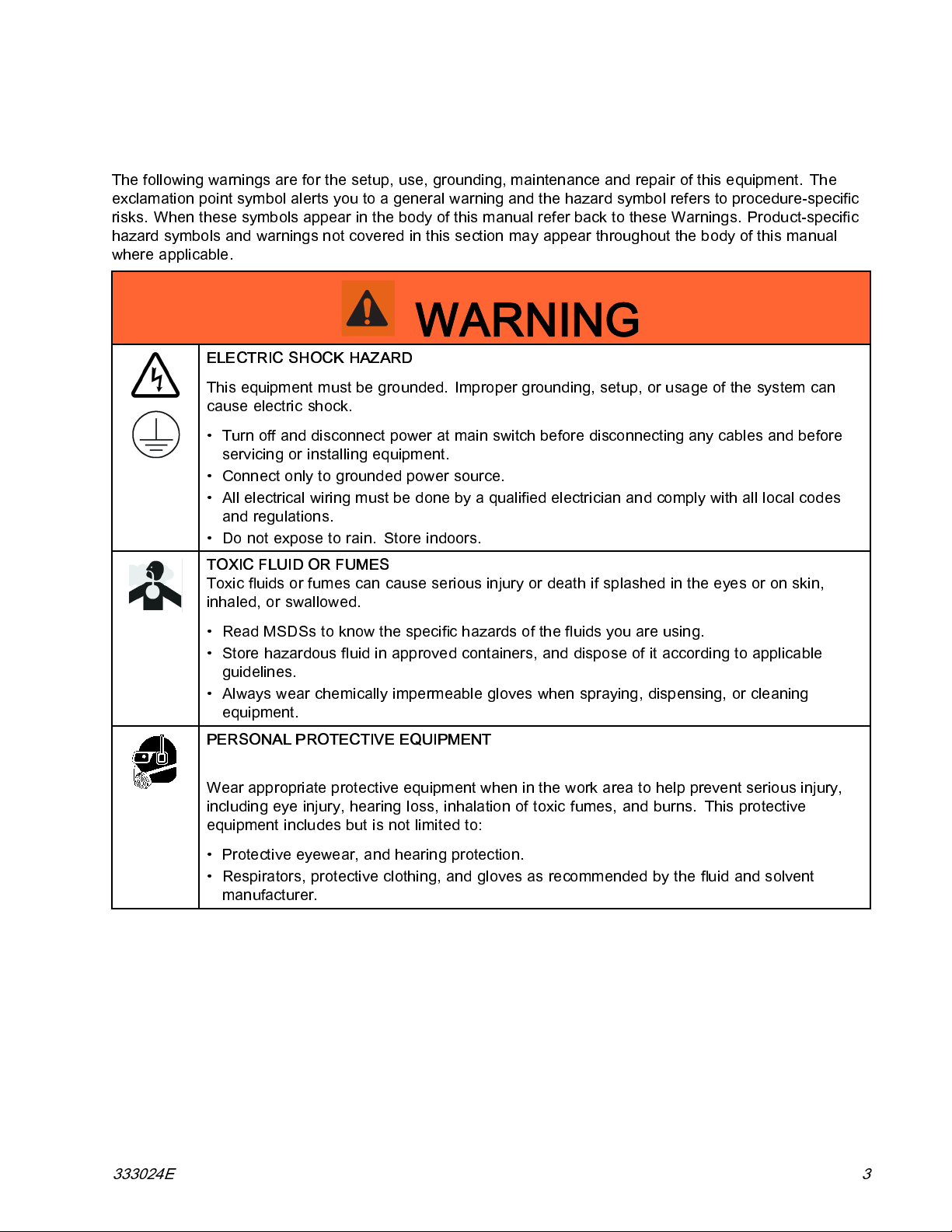
ELECTRIC SHOCK HAZARD
This equipment must be grounded. Improper grounding, setup, or usage of the system can
cause electric shock.
• Turn off and dis connect power at main switch before disconnecting any cables and before
servicing or installing equipment.
• Connect only to grounded power source.
• All electrical wiring must be done by a qualified electrician and comply with all local codes
and regulations.
• Do not expose to rain. Store indoors.
TOXIC FLUID OR FUMES
Toxic fluids or fumes can cause serious injury or death if splashed in the eyes or on skin,
inhaled, or swallowed.
• Read MSDSs to know the specific hazards of the fluids you are using.
• Store hazardous fluid in approved containers, and dispose of it according to applicable
guidelines.
• Always wear chemic al ly i mpe rmeab le gloves when spraying, dispensing, or clean ing
equipment.
PERSONAL PROTECTIVE EQUIPMENT
Wear appropriate protective equipment when in the work area to help prevent serious injury,
including eye injury, hearing loss, inhalation of toxic fu mes , and burns. This protective
equipment includes b ut is not limit ed to:
• Protective eyewear, and hearing protection.
• Respirators, protective clothing, and gloves as recommended by the fluid and solvent
manufacturer.
333024E 3
Page 4
Warnings
WARNING
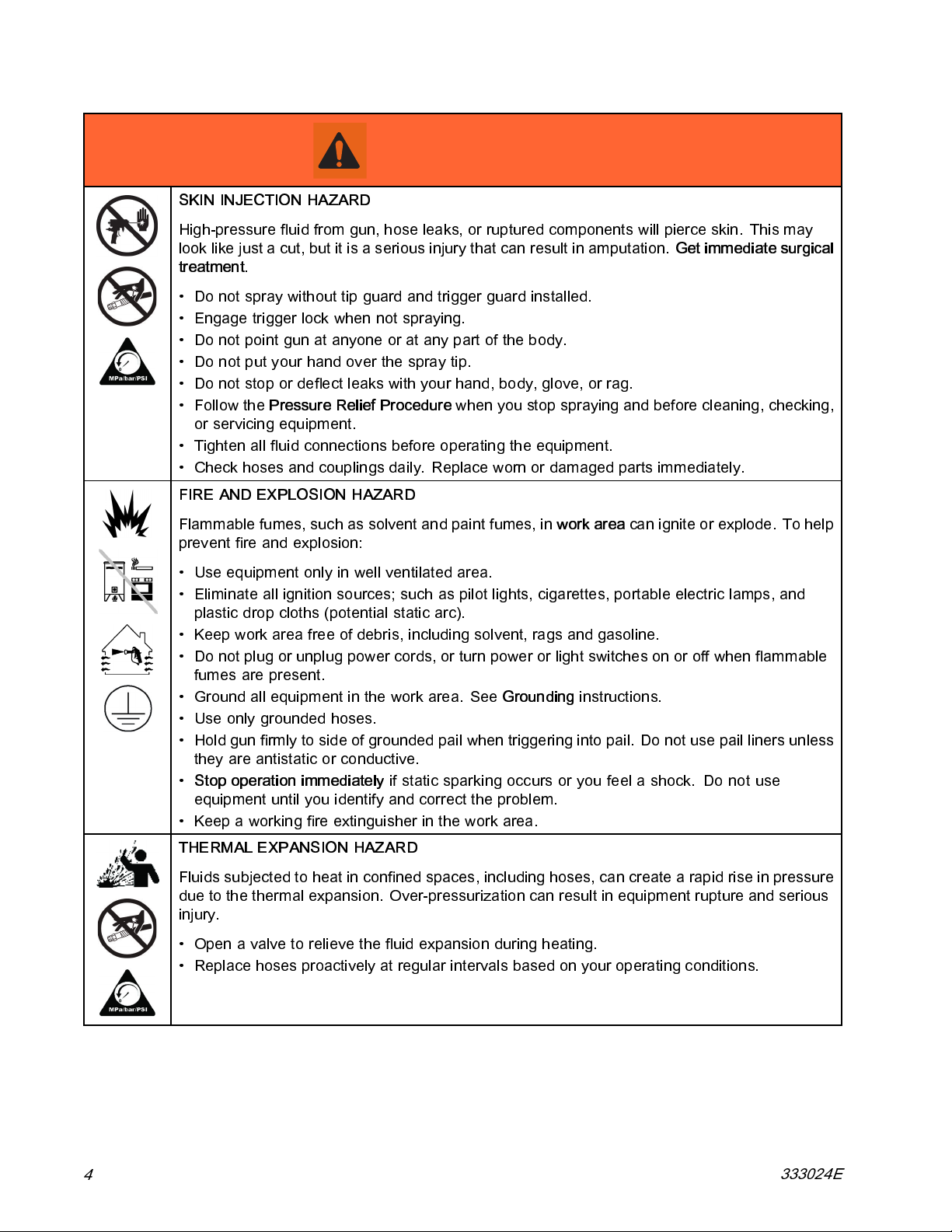
SKIN INJECTION HAZARD
High-pressure fluid from gun, hose leaks, or rup tured com ponents will pierce skin. This may
look like just a cut, but it is a serious injury that can result in amputation.
treatment
• Do not spray without tip guard and trigger guard installed.
• Engage trigger lock when not spraying.
• Do not point gun a t anyone or at any part of the body.
• Do not put your hand over the spray tip.
• Do not stop or deflect leaks with your hand, body, glove, or rag.
• Follow the
or servicing equipment.
• Tighten all fluid connections before operating the equipment.
• Check hoses and couplings daily. Replace worn or damaged parts immediately.
FIRE AND EXPLOSION HAZARD
.
Pressure Relief Procedure
when you stop spraying an d before cleaning, checking,
Get immediate surgical
Flammable fumes, such as solvent and pain t fumes, in
prevent fire and explosion:
• Use equipment only in well ventilated area.
• Eliminate all ignition sources; such as pilot lights, cigarettes, portable electric lamps, and
plastic drop cloths (potential static arc).
• Keep work area free of debris, including solvent, rags and gasoline.
• Do not plug or unplug power cords, or turn power or light switches on or off when flammable
fumes are present.
• Ground all equipment in the work area. See
• Use only grounded hoses.
• Hold gun firmly to side of grounded pail when triggering into pail. Do not use pail liners unless
they are antistatic or conductive.
•
Stop operation immediately
equipment until you identify and correct the problem.
• Keep a working fire extinguisher in the work area.
THERMAL EXPANSION HAZARD
Fluids subjected to heat in confined spaces, including hoses, can create a rapid rise in pressure
due to the thermal expansion. Over-pressurization can result in eq u ipment rupture and serious
injury.
• Open a valve to relieve the fluid expansion during heating.
• Replace hoses proactively at regular intervals based on your operating conditions.
if static sparking occurs or you feel a shock.Do not use
Grounding
work area
instructions.
canigniteorexplode.Tohelp
4
333024E
Page 5
Warnings
WARNING
PRESSURIZED ALUMINUM PARTS HAZARD
Use of fl ui ds that are incompatible with aluminum in pressu riz ed equipment can cause serious
chemical reaction and equipment rupture. Failure to follow this warning can result in death,
serious injury, or property damage.
• Do not use 1,1,1-trichloroethane, methylene chloride, other halogenated hydrocarbon
solvents or fluids containing such solvents.
• Many other fluids may co ntain chemicals that can react with aluminum. Contact your material
supplier for compatibility.
PLASTIC PARTS CLEANING SOLVENT HAZARD
Many solvents can degrade plastic parts and cause them to fail, which could cause serious
injury or property damage.
• Use only compatible water-based solvents to clean pl as tic structural or pressure-containing
parts.
•See
Technical Data
solvent manufacturer’s MSDSs and recommendations.
in this and all other equipment instruction manuals. Read fluid and
EQUIPMENT MISUSE HAZARD
Misuse can cause death or serious injury.
• Do not operate the unit when fatigued or under the influence of drugs or alcohol.
• Do not exceed the maximum working pressure or temperature rating of the lowest rated
system component. See
• Use fluids and solvents that are compatible with equipment wetted parts. See Technical Data
in all equipment manuals. Read fluid and solvent manufacturer’s warnings. For complete
information about your material, request MSDS from distribu tor or retailer.
• Do not leave the work area while equipment is energized or under pressure.
• Turn off all equipment and follow the
• Check equipment daily. Repair or replace worn or damaged parts immediately with genuine
manufacturer’s replacement parts only.
• Do not alter or modify equipmen t. Alterations or modifications may void agency approvals
and create safety hazards.
• Make sure all equipment is rated and approved for the environment in which you are using it.
• Use equipment only for its intended purpose. Call your distributor for information.
• Route hoses and cables away from traffic areas, sharp edges, moving parts, and hot surfa ces.
• Do not kink or over bend hoses or use hoses to pull equipment.
• Keep children and animals away from work area.
• Comply with all applicable safety regulations.
Technical Data
Pressure Relief Procedure
in all equipment manuals.
when equipment is not in use.
333024E 5
Page 6
Warnings
WARNING
MOVING PARTS HAZARD
Moving parts can pinch, cut or amputa te fingers and other body parts.
• Keep clear of moving parts.
• Do not operate equipment with protective guards or covers removed.
• Pressurized equipment can start without warning. Before checking, moving, or servicing
equipment, follow the
BURN HAZAR D
Equipment surfaces and fluid that is heated can become very hot during operation. To avoid
severe burns:
• Do not touch hot fluid or equipment.
Pressure Relief Procedure
and disconnect all power sources.
6 333024E
Page 7
Important Isocyanate Information
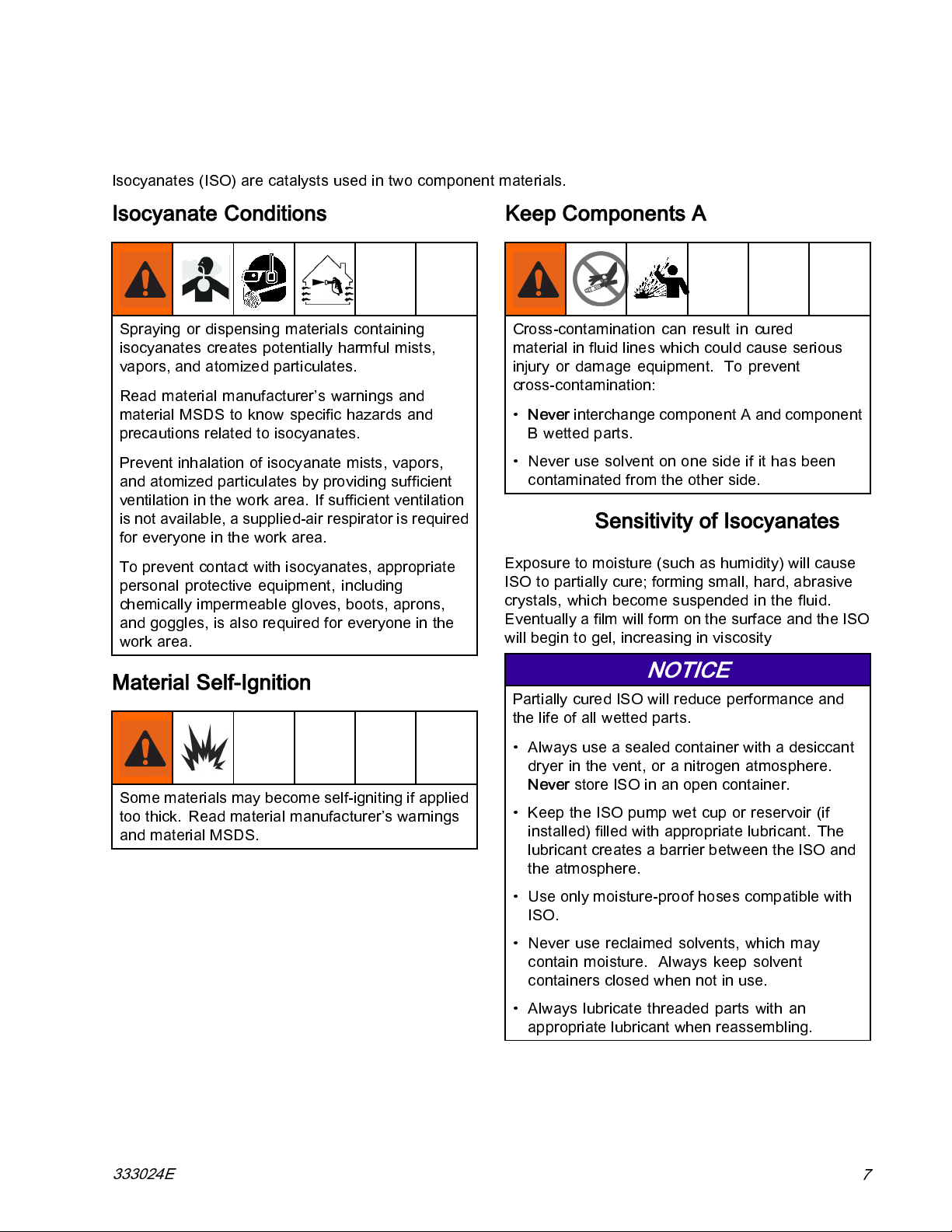
Isocyanates (ISO) are catalysts used in two component materials.
Important Isocyanate Information
Isocyanate Conditions
Spraying or dispensing materials containing
isocyanates creates potentially harmful mists ,
vapors, and atomized particulates.
Read material manufacturer’s warnings and
material MSDS to know specific hazards and
precautions related to isocyanates.
Prevent inhalation of isocyanate mists, vapors,
and atomized particulates by providing sufficient
ventilation in the work area. If sufficient ventilation
is n ot available, a suppl ied-air respirator is required
for everyone in the work area.
To prevent contact with isocyanates, appropriate
personal protective equipment, including
chemically imperm eab le gl ov es , bo ots, ap rons ,
and goggles, is also required for everyone in the
work area.
Keep Components A and B Separate
Cross-contamination can result in cured
material in fluid lines which could cause serious
injury or damage equipment. To prevent
cross-contamination:
•
Never
interchange component A and component
B wetted parts.
• Never use solvent on one s ide if it has been
contaminated from the other side.
Moisture Sensitivity of Isocyanates
Exposure to moisture (such as humidity) will cause
ISO to partially cure; forming small, hard, abrasive
crystals, which become suspended in the fluid.
Eventually a film will form on the surface and the ISO
will begin to gel, increasing in viscosity
Material Self-Ignition
Some materials may become self-igniting if appli ed
too thick. Read material manufacturer’s warnings
and material MSDS.
NOTICE
Partially cured ISO will reduce performance and
the life of all wetted parts.
• Always use a sealed container with a de siccant
dryer in the vent, or a nitrogen atmosphere.
Never
store ISO in an open container.
• Keep the ISO pump wet cup or reservoir (if
installed) filled with appropriate lubricant. The
lubricant creates a barrier between the ISO and
the atmosphere.
• Use only moisture-proof hoses compatible with
ISO.
• Never use reclaimed solvents, which may
contain moisture. Always keep solvent
containers closed when not in use.
• Always lubricate threaded parts with an
appropriate lubricant when reassembling.
333024E
7
Page 8
Important Isocyanate Information
Foam Resins with 245 fa Blowing Agents
Some foam blowing a gen ts will froth at temp eratu res
above 90°F (33°C) when not under pressure,
especially if agitated. To reduce frothing, minimize
preheating in a circulation system.
Changing Materials
NOTICE
Changing the material types used in your
equipment requires special attention to avoid
equipment damage and downtime.
• When changing materials, flush the equipment
multiple times to ensure it is thoroughly clean.
• Always clean the fluid inlet strainers after
flushing.
• Check with your material m anufacturer for
chemical compatibility.
• When changing between ep oxies and urethanes
or polyureas, disassemble and clean all fluid
components and change hoses. Epoxies often
have amines on the B (hardener) side. Polyureas
often have amines on the B (resin) side.
8 333024E
Page 9
Models
Models
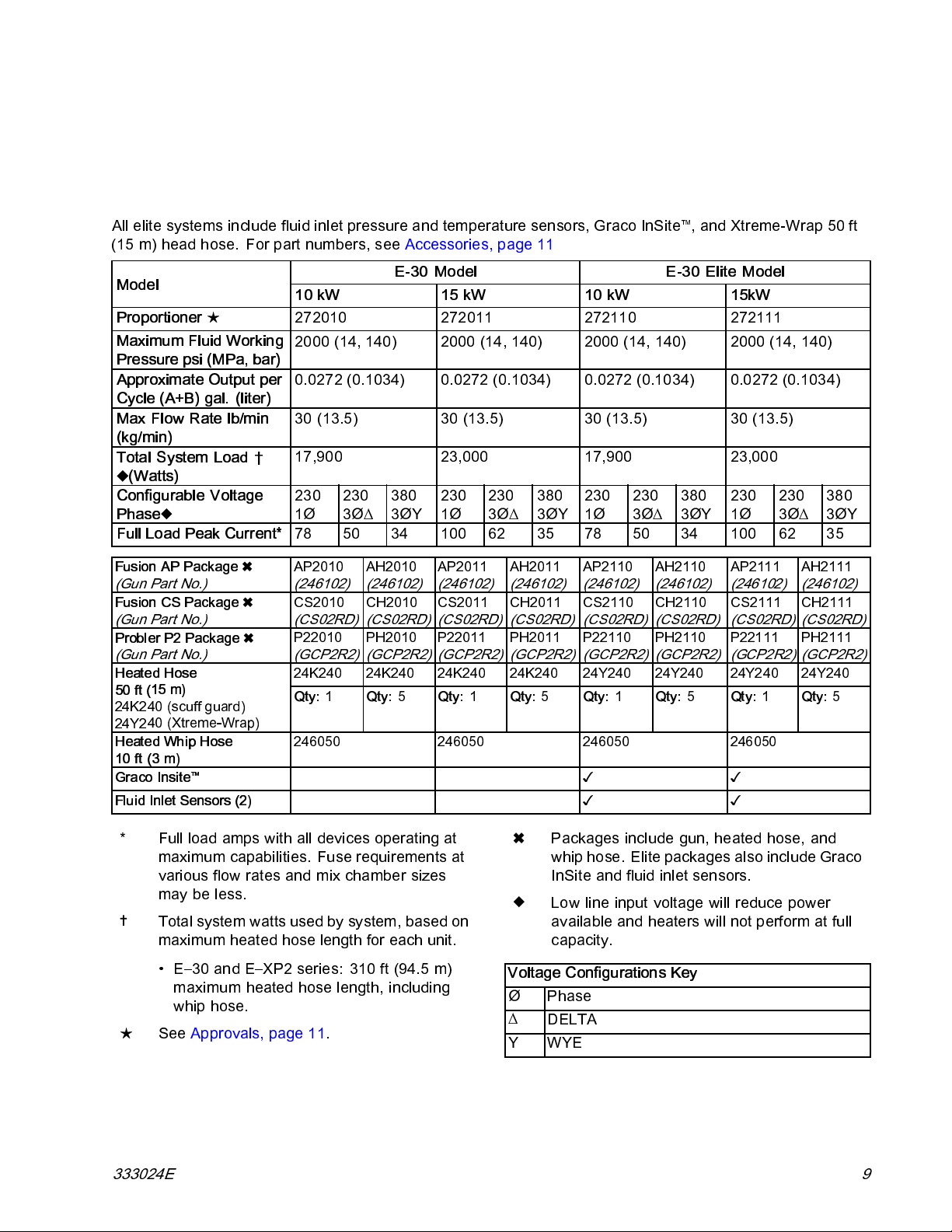
Reactor 2 E-30 and E-30 Elite
All elite systems include fluid inlet pressure and temperature sensors, Graco InSite™, and Xtreme-Wrap 50 ft
(15 m) head hose. For part numbers, see Accessories, page 11
Model
Proportioner
★ 272010 272011 272110 272111
Maximum Fluid Working
Pressure psi (MPa, bar)
Approximate Output per
Cycle (A+B) gal. (liter)
Max Flow Rate lb/min
(kg/min)
Total System Load †
(Watts)
Configurable Voltage
Phase
Full Load Peak Current*
Fusion AP Package
(Gun Part No.)
Fusion CS Package
(Gun Part No.)
Probler P2 Package
(Gun Part No.)
d Hose
Heate
15 m)
50 ft (
40 (scuff guard)
24K2
40 (Xtreme-Wrap)
24Y2
Heated Whip Hose
10 ft (3 m)
Graco Insite
Fluid Inlet Sensors (2)
™
E-30 Model E-30 Elite Model
10 kW 15 kW 10 kW 15kW
2000 (14, 140) 2000 (14, 140) 2000 (14, 140) 2000 (14, 140)
0.0272 (0.1034) 0.0272 (0.1034) 0.0272 (0.1034) 0.0272 (0.1034)
30 (13.5) 30 (13.5) 30 (13.5) 30 (13.5)
17,900 23,000 17,900 23,000
2301Ø230
3Ø∆
380
3ØY
2301Ø230
3Ø∆
380
3ØY
2301Ø230
3Ø∆
380
3ØY
2301Ø230
3Ø∆
380
3ØY
78 50 34 100 62 35 78 50 34 100 62 35
AP2010
(246102)
CS2010
(CS02RD)
P22010
(GCP2R2)
24K24
Qty:
246050 246050 246050 246050
0
1
AH2010
(246102)
CH2010
(CS02RD)
PH2010
(GCP2R2)
0
24K24
Qty:
5
AP2011
(246102)
CS2011
(CS02RD)
P22011
(GCP2R2)
0
24K24
Qty:
1
AH2011
(246102)
CH2011
(CS02RD)
PH2011
(GCP2R2)
0
24K24
Qty:
5
AP2110
(246102)
CS2110
(CS02RD)
P22110
(GCP2R2)
24Y24
Qty:
✓✓
✓✓
0
1
AH2110
(246102)
CH2110
(CS02RD)
PH2110
(GCP2R2)
0
24Y24
Qty:
5
AP2111
(246102)
CS2111
(CS02RD)
P22111
(GCP2R2)
24Y24024Y24
Qty:
1
AH2111
(246102)
CH2111
(CS02RD)
PH2111
(GCP2R2)
Qty:
0
5
Full load amps with all devices operating at
*
maximum capabilities. Fuse requirements at
various flow rates and mix chamber sizes
may be less.
Total system watts used by system, based on
maximum heated hose length for each unit.
• E–30andE–XP2series: 310ft(94.5m)
maximum heated hose length, including
whip hose.
★
See Approvals, page 11.
Packages include gun, heated hose, and
whip hose. Elite packages also include Graco
InSite and fluid inlet sensors.
Low line input voltage will reduce power
available and heaters will not perform at full
capacity.
Voltage Configurations Key
Phase
Ø
∆
DELTA
YWYE
333024E 9
Page 10
Models
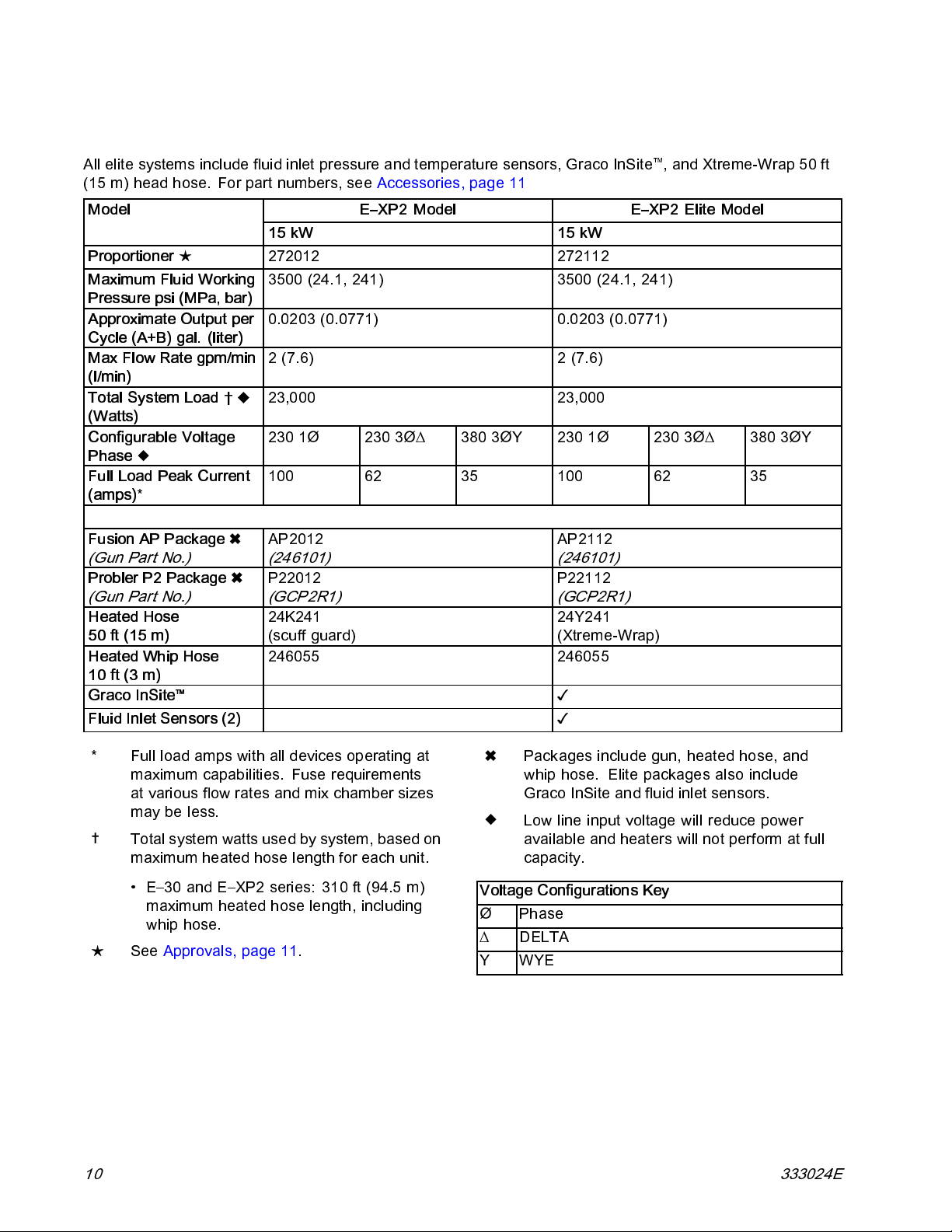
Reactor 2 E-XP2 and E-XP2 Elite
All elite systems include fluid inlet p ressure and temperature sensors, Graco InSite™, and Xtreme-Wrap 50 ft
(15 m) head hose. For part numbers, see Accessories, page 11
Model
Proportioner
Maximum Fluid Working
Pressure psi (MPa, bar)
Approximate Output per
Cycle (A+B) gal. (liter)
Max Flow Rate gpm/min
(l/min)
Total System Load †
(Watts)
Configurable Voltage
Phase
Full Load Peak Current
(amps)
Fusion AP Package
(Gun Part No.)
Probler P2 Package
(Gun Part No.)
Heated Hose
50 ft (15 m)
Heated Whip Hose
10 ft (3 m)
Graco InSite
Fluid Inlet Sensors (2)
★ 272012 272112
*
™
E–XP2 Model E–XP2 Elite Model
15 kW 15 kW
3500 (24.1, 241) 3500 (24.1, 241)
0.0203 (0.0771) 0.0203 (0.0771)
2(7.6) 2(7.6)
23,000 23,000
230 1Ø 230 3Ø∆ 380 3ØY 230 1Ø 230 3Ø∆ 380 3ØY
100 62 35 100 62 35
AP2012
(246101)
P22012
(GCP2R1)
24K241
(scuff guard)
246055 246055
AP2112
(246101)
P22112
(GCP2R1)
24Y241
(Xtreme-Wrap)
✓
✓
Full load amps with all devices operating at
*
maximum capabil iti es . Fuse requirements
at various flow rates and mix chamber sizes
may be less.
Total system watts used by system, based on
maximum heated hose length for each unit.
• E–30 and E–XP2 series: 310 ft (94.5 m)
maximum heated hose length, including
whip hose.
★
See Approvals, page 11.
10 333024E
Packages include gun, heated hose, and
whip hose. Elite packages also include
GracoInSiteandfluidinletsensors.
Low line input voltage wil l reduce power
available and heaters will not perform at full
capacity.
Voltage Configurations Key
Phase
Ø
∆
DELTA
YWYE
Page 11
Approvals
Approvals
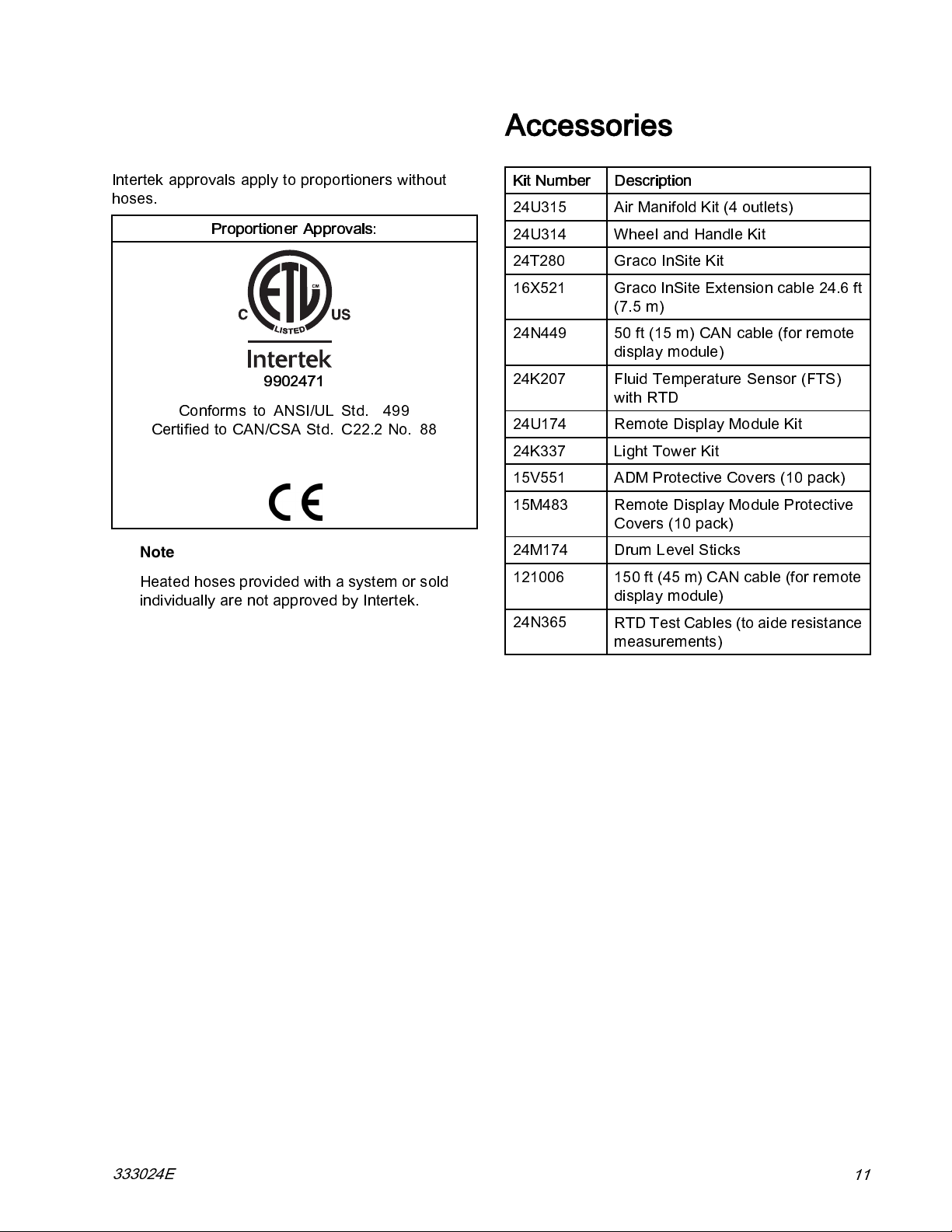
Intertek approvals apply to proportioners without
hoses.
Proportioner Approvals:
9902471
Conforms to ANSI/UL Std. 499
Certified to CAN/CSA Std. C22.2 No. 88
Note
Heated hoses provided with a system or sold
individually are not approved b y Intertek.
Accessories
Kit Number Description
24U315
24U314 Wheel and Handle Kit
24T280
16X521
24N449 50 ft (15 m) CAN cable (for remote
24K207
24U174 Remote Display Module Kit
24K337 Light Tower Kit
15V551 ADM Protective Covers (10 pack)
15M483 Remote Display Module Protective
24M174
121006
24N365
Air Manifold Kit (4 outlets)
GracoInSiteKit
Graco InSite Extension cable 24.6 ft
(7.5 m)
display module)
Fluid Temperature Sensor (FTS)
with RTD
Covers (10 pack)
Drum Level Sticks
150 ft (45 m) CAN cab le (for remote
display module)
RTD Test Cables (to aide resistance
measurements)
333024E
11
Page 12
Supplied Manuals
Supplied Manuals
The following manuals are shipped with the Reactor
2. Refer to these manuals for detailed equipment
information.
Manuals are also available at www.grac o.com.
Manual Description
333023 Reactor 2 E-30 and E-XP2
Operation
333091
333092 Reactor 2 E-30 and E-XP2
Reactor 2 E-30 and E-XP2 Startup
Quick Guide
Shutdown Quick Guide
Related Manuals
The following manuals are for accessories used with
the Reactor.
Component Manuals in English:
Manuals are available at www.graco.com.
System Manuals
333023
Displacement Pump Manual
309577 Electric Reactor Displacement Pump,
Feed System Manuals
309572 Heated Hose, Instructions-Parts
309852
309815 Feed Pump Kits, Instructions-Parts
309827
Spray Gun Manuals
309550
312666
313213
Accessory Manuals
3A1905
3A1906 Light Tower Kit, Instructions-Parts
3A1907 Remote Display Module Kit,
332735
332736 Handle and Wheel Kit,
333276
Reactor 2 E-30 and E-XP2 Operation
Repair-Parts
Circulation and Return Tube Kit,
Instructions-Parts
Feed Pump Air Supply Kit,
Instructions-Parts
Fusion ™ AP Gun
Fusion ™ CS Gun
®
Probler
Feed Pump Shutdown Kit,
Instructions-Parts
Instructions-Parts
Air Manifold Kit, Instructions-Parts
Instructions-Parts
Graco InSite ™ Kit, Instructions-Parts
P2 Gun
12
333024E
Page 13
Troubleshooting
Troubleshooting
Troubleshoot Errors
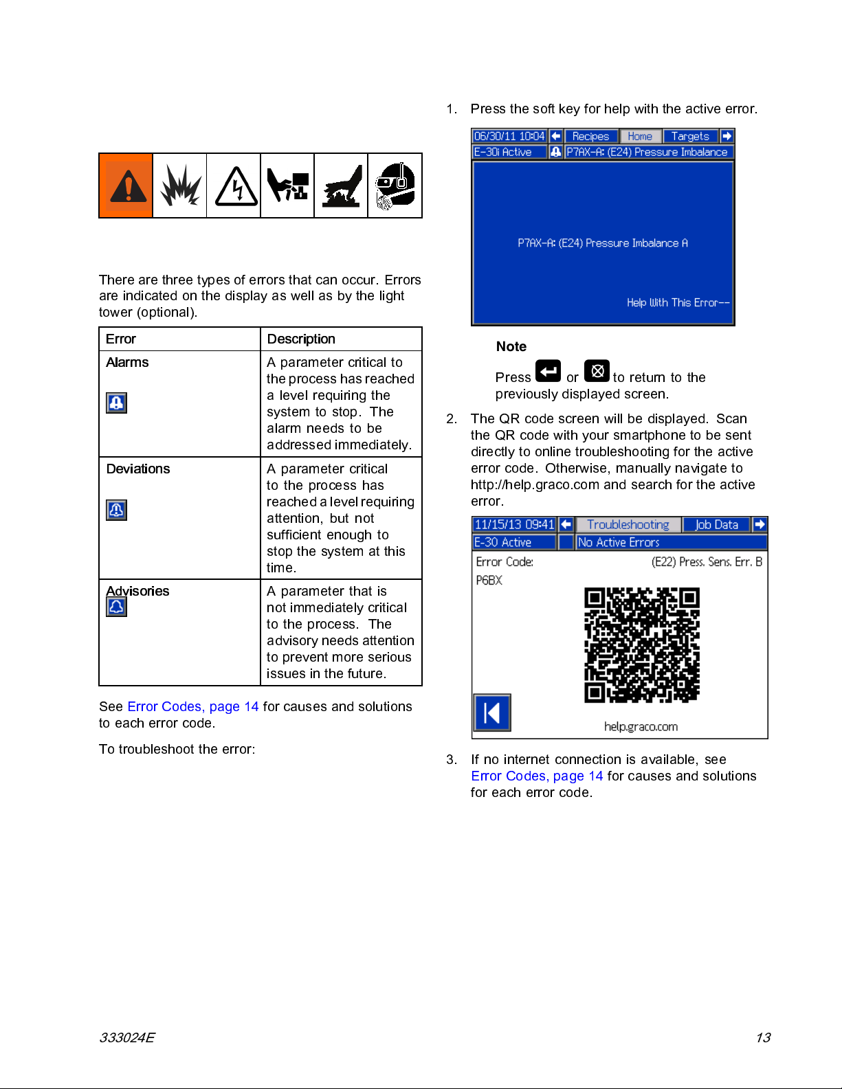
There are three types of errors that can occur. Errors
are indicated on the display as well as by the light
tower (optional).
Error Description
Alarms
Deviations
A parameter critical to
the process has reached
a level requiring the
system to stop. The
alarm needs to be
addressed immediately.
A parameter critical
to the process has
reachedalevel requiring
attention, but not
sufficient enough to
stop the system at this
time.
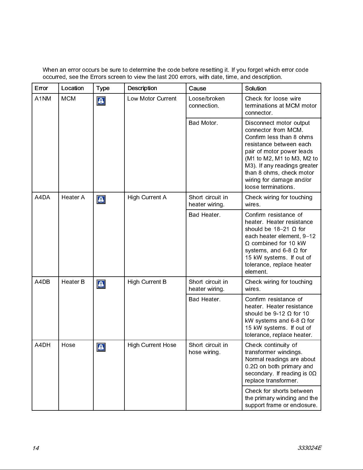
1. Press the soft key for help with the active error.
Note
Press or to return to the
previously displayed screen.
2. TheQRcodescreenwillbedisplayed. Scan
theQRcodewithyoursmartphonetobesent
directly to online troubleshooti ng for the active
error code. Otherwise, manually navigate to
http://help.graco.com and search for the active
error.
Advisories
See Error Codes, page 14 for causes and solutions
to each error code.
To troubleshoot the error:
A parameter that is
not immediately critical
to the process. The
advisory needs attention
to prevent more serious
issues in the future.
3. If no internet connection is available, see
Error Codes, page 14 for c auses and solutions
for each error code.
333024E 13
Page 14
Troubleshooting
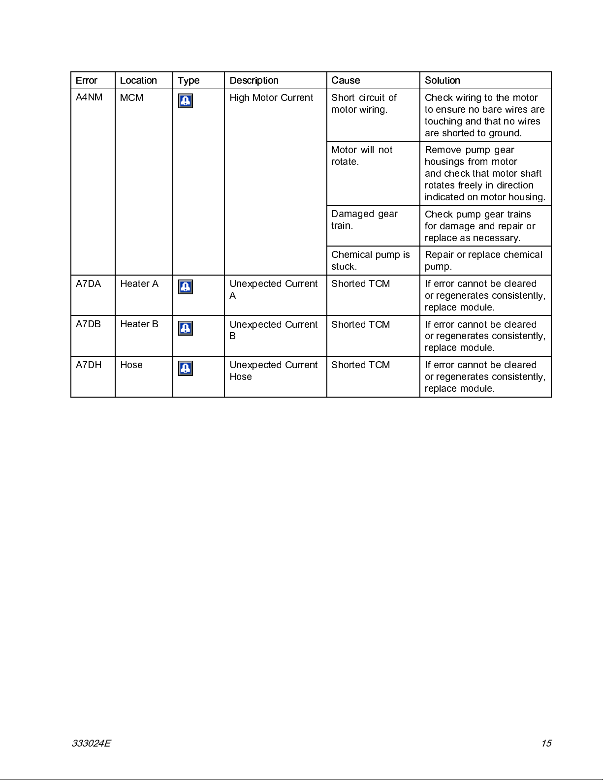
Error Codes
Note
When an error occurs be sure to determine the code before resetting it. If you forget which error code
occurred, see the Errors screen to view the last 200 errors, with date, time, and description.
Error Location Type Description
A1NM
A4DA Heater A High Current A
MCM
Low Motor Current
Cause Solution
Loose/broken
connection.
Bad Motor. Disconnect motor output
Short circuit in
heater wiring.
Bad Heater.
Check for loose wire
terminations at MCM motor
connector.
connector from MCM.
Confirm less than 8 ohms
resistance between each
pair of motor power leads
(M1toM2,M1toM3,M2to
M3). If any readings greater
than 8 ohms, check motor
wiring for damage and/or
loose terminations.
Check wiring for touching
wires.
Confirm resistance of
heater. Heater resistance
should be 18–21 Ω for
each heater element, 9–12
Ω combined for 10 kW
systems, and 6-8 Ω for
15 kW systems. If out of
tolerance, replace heater
element.
A4DB Heater B
A4DH Hose
14
High Current B
High Current Hose Short circuit in
Short circuit in
heater wiring.
Bad Heater.
hose wiring.
Check wiring for touching
wires.
Confirm resistance of
heater. Heater resistance
should be 9-12 Ω for 10
kW systems and 6-8 Ω for
15 kW systems. If out of
tolerance, replace heater.
Check continuity of
transformer windings.
Normal readings are about
0.2Ω on both primary and
secondary. If reading is 0Ω
replace transformer.
Check for shorts between
the primary winding and the
support frame or enclosure.
333024E
Page 15
Troubleshooting
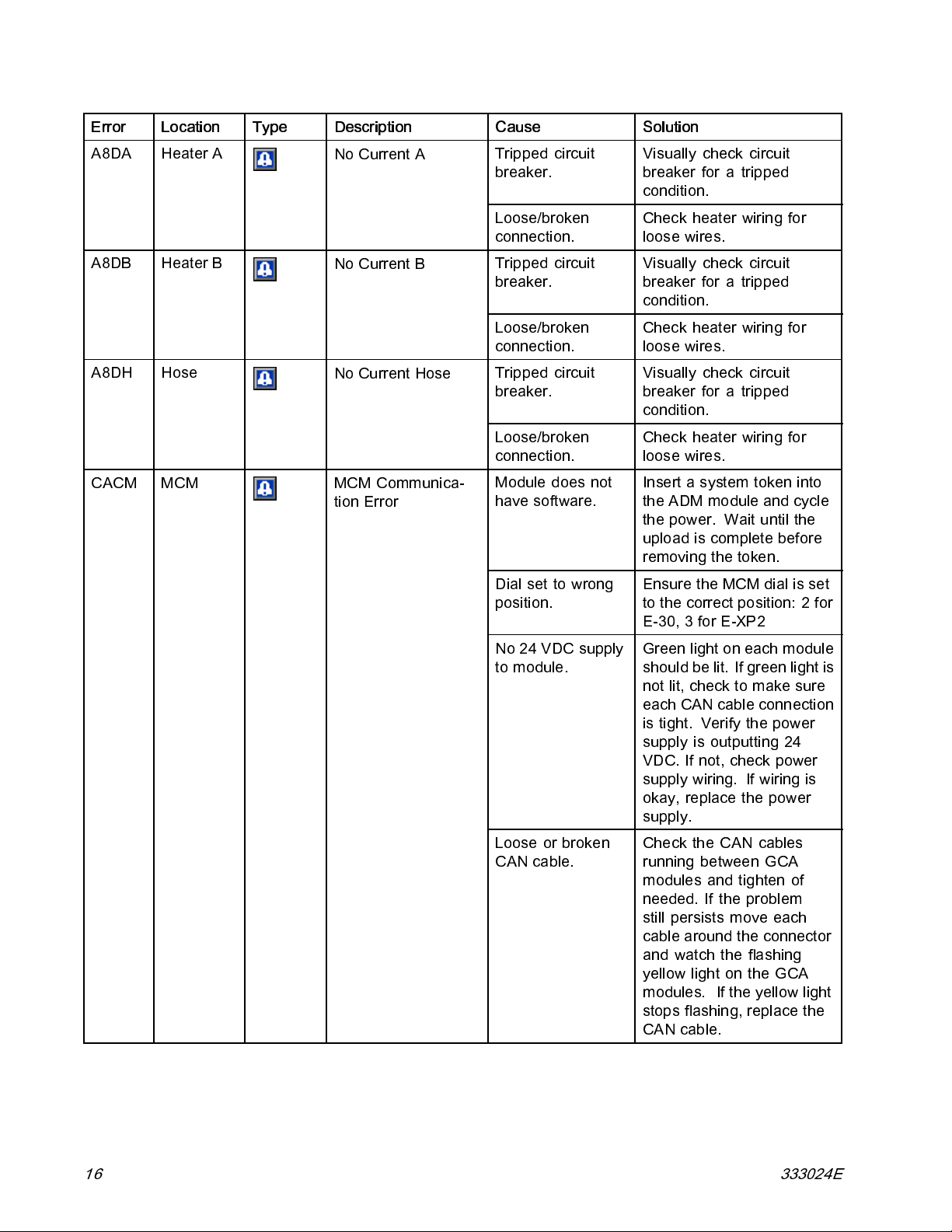
Error Location Type Description
A4NM
A7DA Heater A
A7DB Heater B
A7DH Hose
MCM
High Motor Current
Unexpected CurrentAShorted TCM If error cannot be cleared
Unexpected CurrentBShorted TCM If error cannot be cleared
Unexpected Current
Hose
Cause Solution
Short circuit of
motor wiring.
Motor will not
rotate.
Damaged gear
train.
Chemical pump is
stuck.
Shorted TCM If error cannot be cleared
Check wiring to the motor
to ensure no bare wires are
touching and that no wires
are shorted to ground.
Remove pump gear
housings from motor
and check that motor shaft
rotates freely in direction
indicated on motor housing.
Check pump gear trains
for damage and repair or
replace as necessary.
Repair or replace chemical
pump.
or regenerates consistently,
replace module.
or regenerates consistently,
replace module.
or regenerates consistently,
replace module.
333024E 15
Page 16
Troubleshooting
Error Location Type Description
A8DA Heater A
A8DB Heater B
A8DH Hose
CACM MCM MCM Communica-
No Current A
No Current B
No Current Hose
tion Error
Cause Solution
Tripped circuit
breaker.
Loose/broken
connection.
Tripped circuit
breaker.
Loose/broken
connection.
Tripped circuit
breaker.
Loose/broken
connection.
Module does not
have software.
Visually check circuit
breaker for a tripped
condition.
Check heater wiring for
loose wires.
Visually check circuit
breaker for a tripped
condition.
Check heater wiring for
loose wires.
Visually check circuit
breaker for a tripped
condition.
Check heater wiring for
loose wires.
Insert a system token into
the ADM module and cycle
the power. Wait until the
upload is complete before
removing the token.
Dial set to wrong
position.
No 24 VDC supply
to module.
Loose or broken
CAN cable.
Ensure the MCM dial is set
to the correct position: 2 for
E-30, 3 for E-XP2
Green light on each module
should be lit. If green light is
not lit, check to make sure
each CAN cable connection
is tight. Verify the power
supply is outputting 24
VDC. If not, check power
supply wiring. If wiring is
okay, replace the power
supply.
Check the CAN cables
running between GCA
modules and tighten of
needed. If the problem
still persists move each
cable around the connector
and watch the flashing
yellow light on the GCA
modules. If the yellow light
stops flashing, replace the
CAN cable.
16 333024E
Page 17
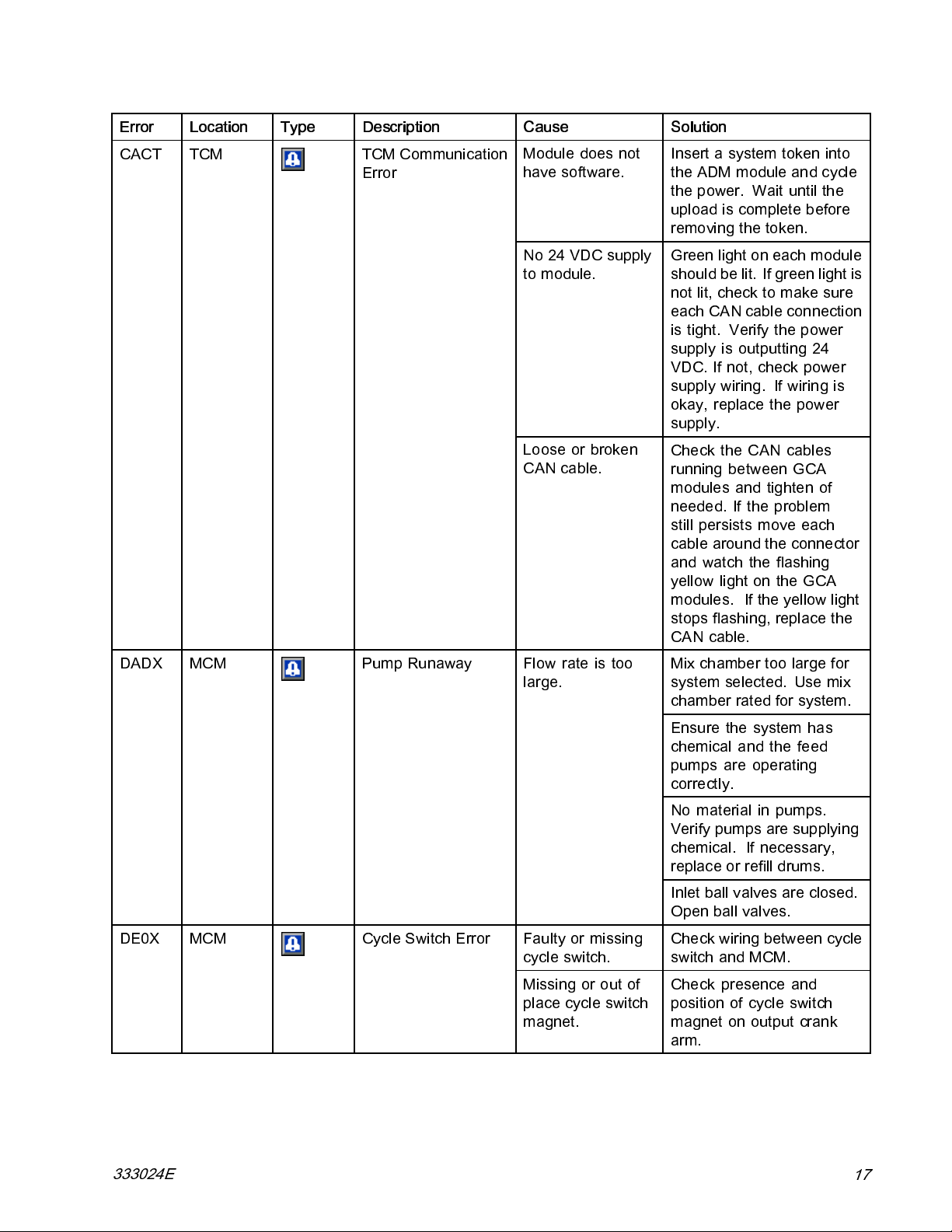
Troubleshooting
Error Location Type Description
CACT TCM TCM Communication
Error
Cause Solution
Module does not
have software.
No 24 VDC supply
to module.
Loose or broken
CAN cable.
Insert a system token into
the ADM module and cycle
the power. Wait until the
upload is complete before
removing the token.
Green light on each module
should be lit. If green light is
not lit, check to make sure
each CAN cable connection
is tight. Verify the power
supply is outputting 24
VDC. If not, check power
supply wiring. If wiring is
okay, replace the power
supply.
Check the CAN cables
running between GCA
modules and tighten of
needed. If the problem
still persists move each
cable around the connector
and watch the flashing
yellow light on the GCA
modules. If the yellow light
stops flashing, replace the
CAN cable.
DADX MCM Pump Runaway Flow rate is too
large.
DE0X
MCM
Cycle Switch Error
Faulty or missing
cycle switch.
Missing or out of
place cycle switch
magnet.
Mix chamber too large for
system selected. Use mix
chamber rated for system.
Ensure the system has
chemical and the feed
pumps are operating
correctly.
No material in pumps.
Verify pumps are supplying
chemical. If necessary,
replace or refill drums.
Inlet ball valves are closed.
Open ball valves.
Check wiring betwe en cycle
switch and MCM.
Check presence and
position of cycle switch
magnet on output crank
arm.
333024E
17
Page 18
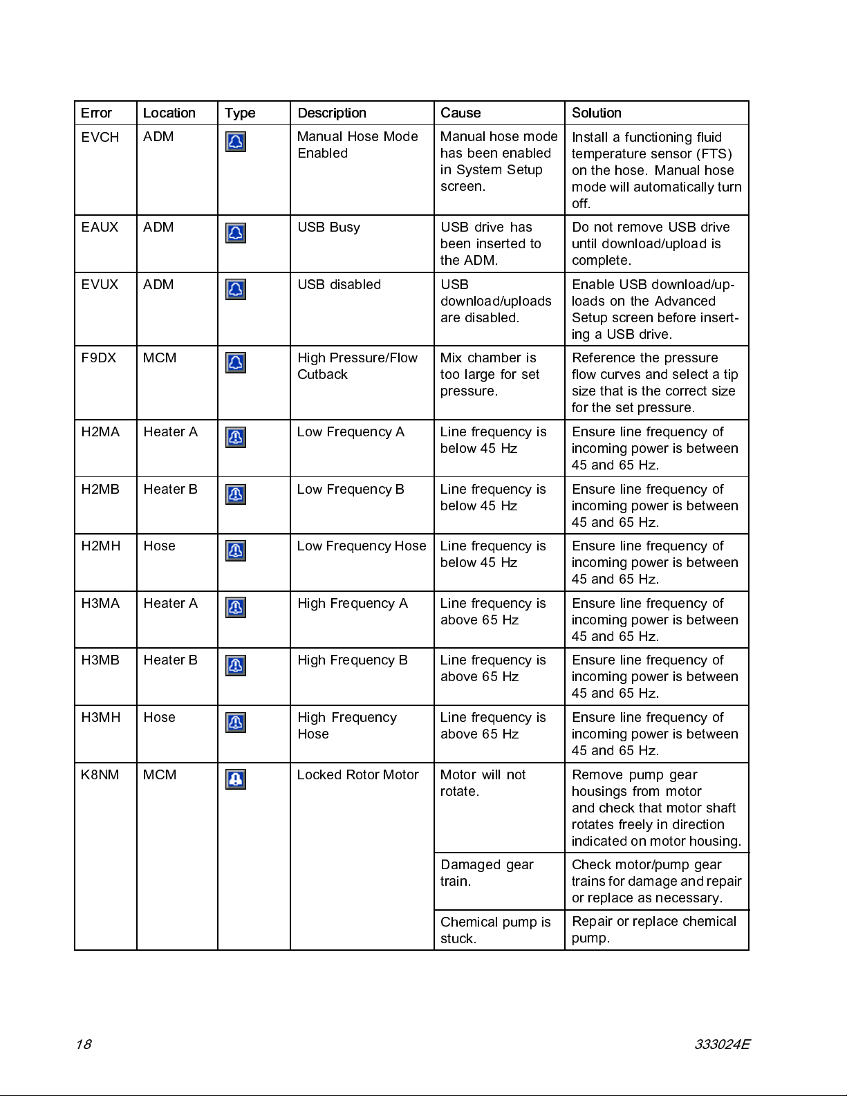
Troubleshooting
Error Location Type Description
EVCH
EAUX ADM
EVUX ADM
F9DX
H2MA Heater A Low Frequency A Line frequency is
H2MB Heater B Low Frequency B
ADM
MCM
Manual Hose Mode
Enabled
USB Busy USB drive has
USB disabled USB
High Pressure/Flow
Cutback
Cause Solution
Manual hose mode
has been enabled
in System Setup
screen.
been ins erted to
the ADM.
download/uploads
are disabled.
Mix chamber is
too large for set
pressure.
below 45 Hz
Line frequency is
below 45 Hz
Install a functioning fluid
temperature sensor (FTS)
on the hose. Manual hose
mode will automatically turn
off.
Do not remove USB drive
until download/upload is
complete.
Enable USB download/up-
loads on the Advanced
Setupscreenbeforeinsert-
ing a USB drive.
Reference the pressure
flow curves and select a tip
size that is the correct size
for the set pressure.
Ensure line frequency of
incoming power is between
45and65Hz.
Ensure line frequency of
incoming power is between
45and65Hz.
H2MH Hose Low Frequency Hos e
H3MA Heater A High Frequency A
H3MB Heater B High Frequency B
H3MH Hose High Frequency
Hose
K8NM MCM Locked Rotor Motor
Line frequency is
below 45 Hz
Line frequency is
above65Hz
Line frequency is
above65Hz
Line frequency is
above65Hz
Motor will not
rotate.
Damaged gear
train.
Chemical pump is
stuck.
Ensure line frequency of
incoming power is between
45and65Hz.
Ensure line frequency of
incoming power is between
45and65Hz.
Ensure line frequency of
incoming power is between
45and65Hz.
Ensure line frequency of
incoming power is between
45and65Hz.
Remove pump gear
housings from motor
and check that motor shaft
rotates freely in direction
indicated on motor housing.
Check motor/pump gear
trains for damage and repair
or replace as necessary.
Repair or replace chemical
pump.
18 333024E
Page 19
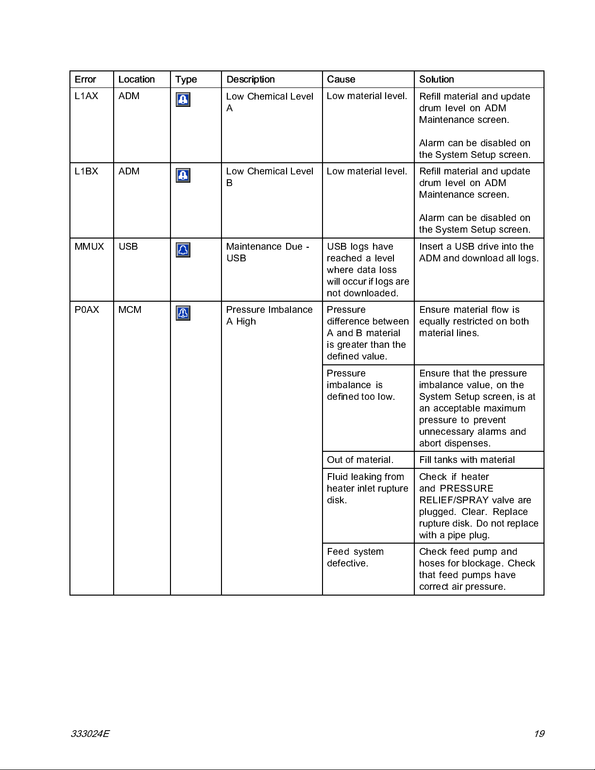
Troubleshooting
Error Location Type Description
L1AX ADM
L1BX ADM
MMUX
P0AX
USB
MCM
Low Chemical Level
A
Low Chemical Level
B
Maintenance Due -
USB
Pressure Imbalance
AHigh
Cause Solution
Low material level.
Low material level.
USB logs have
reached a level
where data loss
will occur if logs are
not downloaded.
Pressure
difference between
AandBmaterial
is greater than the
defined value.
Refill material and update
drum level on ADM
Maintenance screen.
Alarm can be disabled on
the System Setup screen.
Refill material and update
drum level on ADM
Maintenance screen.
Alarm can be disabled on
the System Setup screen.
InsertaUSBdriveintothe
ADM and download all logs.
Ensure material flow is
equally restricted on both
material lines.
Pressure
imbalance is
defined too low.
Out of material.
Fluid leaking from
heater inlet rupture
disk.
Feed system
defective.
Ensure that the pressure
imbalance value, on the
System Setup screen, is at
an acceptable maximum
pressure to prevent
unnecessary alarms and
abort dispenses.
Fill tanks with material
Check if heater
and PRESSURE
RELIEF/SPRAY valve are
plugged. Clear. Replace
rupture disk. Do not replace
withapipeplug.
Checkfeedpumpand
hoses for blockage. Check
that feed pumps have
correct air pressure.
333024E 19
Page 20
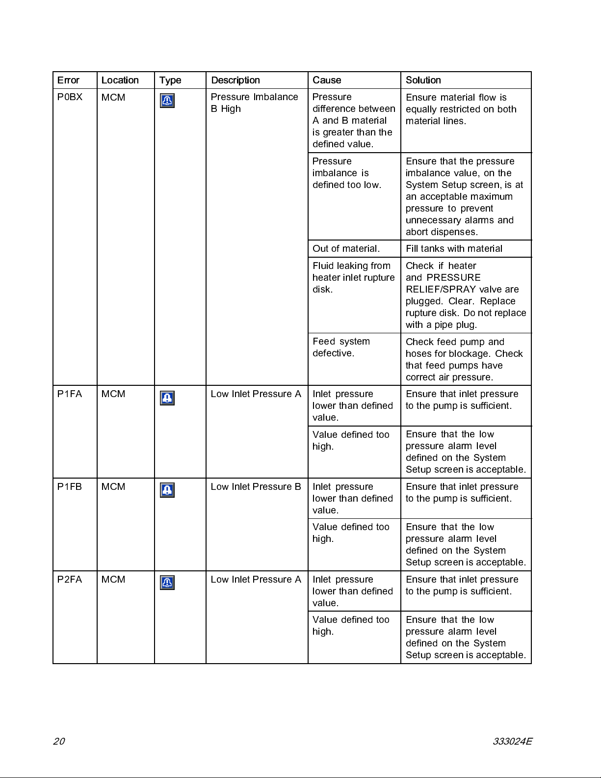
Troubleshooting
Error Location Type Description
P0BX
MCM
Pressure Imbalance
BHigh
Cause Solution
Pressure
difference between
AandBmaterial
is greater than the
defined value.
Pressure
imbalance is
defined too low.
Out of material. Fill tanks with material
Fluid leaking from
heater inlet rupture
disk.
Feed system
defective.
Ensure material flow is
equally restricte d on b oth
material lines.
Ensure that the pressure
imbalance value, on the
System Setup screen, is at
an acceptable maximum
pressure to prevent
unnecessary alarms and
abort dispenses.
Check if heater
and PRESSURE
RELIEF/SPRAY valve are
plugged. Clear. Replace
rupture disk. Do not replace
withapipeplug.
Check feed pump and
hoses for blockage. Check
that feed pumps have
correct air pressure.
P1FA
P1FB
P2FA
MCM
MCM
MCM
Low Inlet Pressure A
Low Inlet Pressure B
Low Inlet Pressure A
Inlet pressure
lower than defined
value.
Value defined too
high.
Inlet pressure
lower than defined
value.
Value defined too
high.
Inlet pressure
lower than defined
value.
Value defined too
high.
Ensure that inlet pressure
to the pump is sufficient.
Ensure that the low
pressure alarm level
defined on the System
Setup screen is acceptable.
Ensure that inlet pressure
to the pump is sufficient.
Ensure that the low
pressure alarm level
defined on the System
Setup screen is acceptable.
Ensure that inlet pressure
to the pump is sufficient.
Ensure that the low
pressure alarm level
defined on the System
Setup screen is acceptable.
20 333024E
Page 21
Troubleshooting
Error Location Type Description
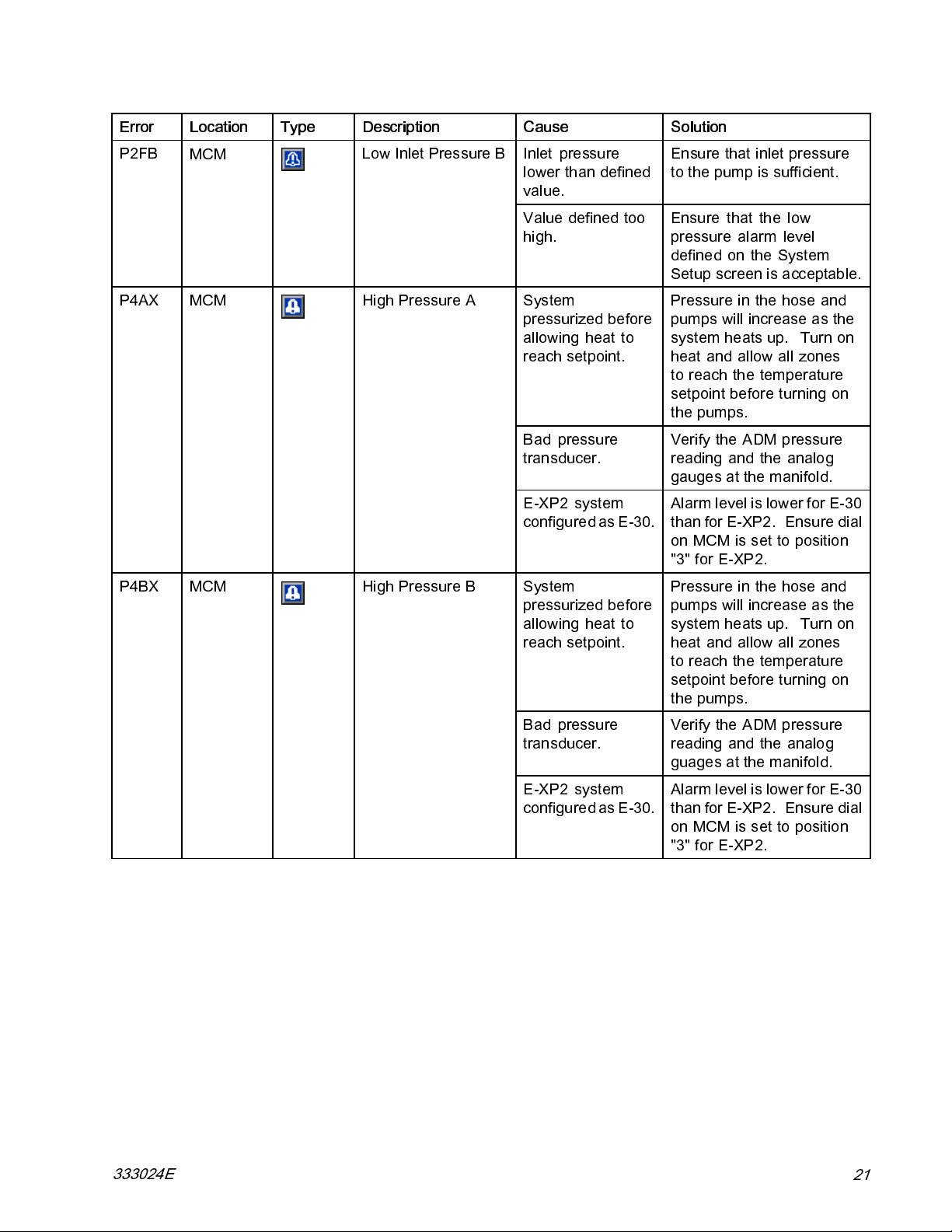
P2FB
P4AX MCM High Pressure A
MCM
Low Inlet Pressure B
Cause Solution
Inlet pressure
lower than defined
value.
Value defined too
high.
System
pressurized before
allowing heat to
reach setpoint.
Bad pressure
transducer.
E-XP2 system
configured as E-30.
Ensure that inlet pressure
to the pump is sufficient.
Ensure that the low
pressure alarm level
defined on the System
Setup screen is accep tab le.
Pressure in the hose and
pumps will increase as the
system heats up. Turn on
heat and allow all zones
to reach the temperature
setpoint before turning on
the pumps.
Verify the ADM pressure
readingandtheanalog
gauges at the manifold.
Alarm level is lower for E-30
than for E-XP2. Ensure dial
on MCM is set to position
"3" for E-XP2.
P4BX
MCM
High Pressure B
System
pressurized before
allowing heat to
reach setpoint.
Bad pressure
transducer.
E-XP2 system
configured as E-30.
Pressure in the hose and
pumps will increase as the
system heats up. Turn on
heat and allow all zones
to reach the temperature
setpoint before turning on
the pumps.
Verify the ADM pressure
readingandtheanalog
guages at the manifold.
Alarm level is lower for E-30
than for E-XP2. Ensure dial
on MCM is set to position
"3" for E-XP2.
333024E
21
Page 22
Troubleshooting
Error Location Type Description
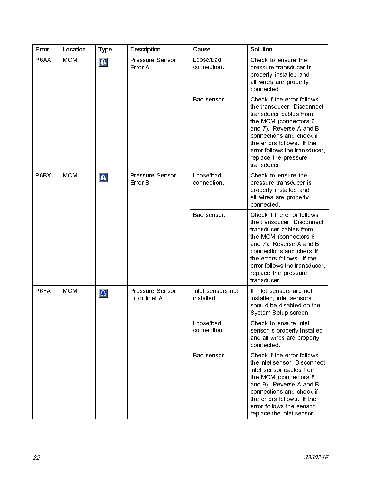
P6AX
P6BX
MCM
MCM
Pressure Sensor
Error A
Pressure Sensor
Error B
Cause Solution
Loose/bad
connection.
Bad sensor.
Loose/bad
connection.
Bad sensor.
Check to ensure the
pressure transducer is
properly installed and
all wires are properly
connected.
Check if the error fo llows
the transducer. Disconnect
transducer cables from
the MCM (connectors 6
and7). ReverseAandB
connections and check if
the errors follows. If the
error follows the transducer,
replace the pressure
transducer.
P6FA MCM Pressure Sensor
Error Inlet A
22
Inlet sensors not
installed.
Loose/bad
connection.
Bad sensor.
If inlet sensors are not
installed, inlet sensors
should be disabled on the
System Setup screen.
Check to ensure inlet
sensor is properly installed
and all wires are properly
connected.
Check if the error fo llows
the inlet sensor. Disconnect
inlet sens or cables from
the MCM (connectors 8
and9). ReverseAandB
connections and check if
the errors follows. If the
error follows the sensor,
replace the inlet sensor.
333024E
Page 23
Troubleshooting
Error Location Type Description
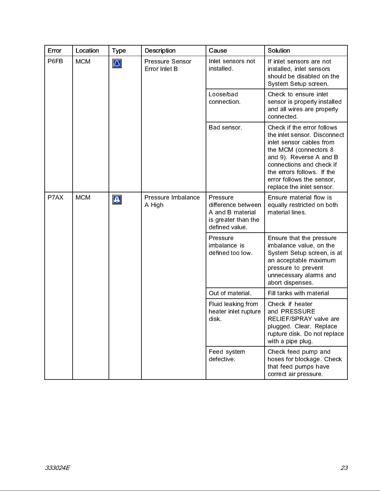
P6FB
P7AX
MCM
MCM
Pressure Sensor
Error Inlet B
Pressure Imbalance
AHigh
Cause Solution
Inlet sensors not
installed.
Loose/bad
connection.
Bad sensor.
Pressure
difference between
AandBmaterial
is greater than the
defined value.
If inlet sensors are not
installed, inlet sensors
should be disabled on the
System Setup screen.
Checktoensureinlet
sensor is properly installed
and all wires are properly
connected.
Check if the error fol lows
the inlet sensor. Disconnect
inlet sensor cables from
the MCM (connectors 8
and9). ReverseAandB
connections and check if
the errors follows. If th e
error follows the sensor,
replace the inlet sensor.
Ensure material flow is
equally restricted on both
material lines.
Pressure
imbalance is
defined too low.
Out of material.
Fluid leaking from
heater inlet rupture
disk.
Feed system
defective.
Ensure that the pressure
imbalance value, on the
System Setup screen, is at
an acceptable maximum
pressure to prevent
unnecessary alarms and
abort dispenses.
Fill tanks with material
Check if heater
and PRESSURE
RELIEF/SPRAY valve are
plugged. Clear. Replace
rupture disk. Do not replace
withapipeplug.
Checkfeedpumpand
hoses for blockage. Check
that feed pumps have
correct air pressure.
333024E 23
Page 24
Troubleshooting
Error Location Type Description
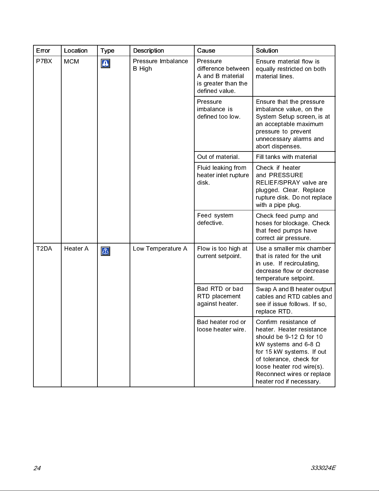
P7BX
MCM
Pressure Imbalance
BHigh
Cause Solution
Pressure
difference between
AandBmaterial
is greater than the
defined value.
Pressure
imbalance is
defined too low.
Out of material. Fill tanks with material
Fluid leaking from
heater inlet rupture
disk.
Feed system
defective.
Ensure material flow is
equally restricte d on b oth
material lines.
Ensure that the pressure
imbalance value, on the
System Setup screen, is at
an acceptable maximum
pressure to prevent
unnecessary alarms and
abort dispenses.
Check if heater
and PRESSURE
RELIEF/SPRAY valve are
plugged. Clear. Replace
rupture disk. Do not replace
withapipeplug.
Check feed pump and
hoses for blockage. Check
that feed pumps have
correct air pressure.
T2DA Heater A Low Temperature A
Flow is too high at
current setpoint.
Bad RTD or bad
RTD placement
against heater.
Bad heater rod or
loose heater wire.
Use a smaller mix chamber
that is rated for the unit
in use. If recirculating,
decrease flow or decrease
temperature setpoint.
Swap A and B heater output
cables and RTD cables and
see if issue follows. If so,
replace RTD.
Confirm resistance of
heater. Heater resistance
should be 9-12 Ω for 10
kW systems and 6-8 Ω
for 15 kW systems. If out
of tolerance, check for
loose heater rod wire(s).
Reconnect wires or replace
heater rod if necessary.
24
333024E
Page 25
Troubleshooting
Error Location Type Description
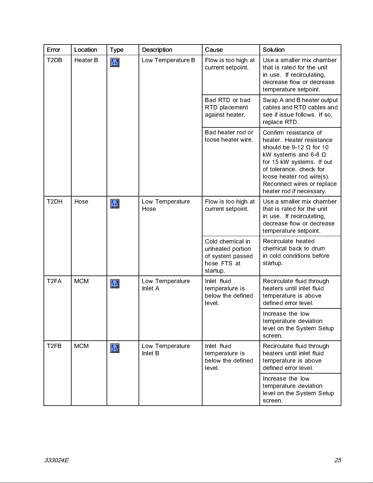
T2DB Heater B Low Temperature B
T2DH Hose Low Temperature
Hose
Cause Solution
Flow is too high at
current setpoint.
Bad RTD or bad
RTD placement
against heater.
Bad heater rod or
loose heater wire.
Flow is too high at
current setpoint.
Use a smaller mix chamber
that is rated for the unit
in use. If recircul ating,
decrease flow or decrease
temperature setpoint.
Swap A and B hea ter output
cables and RTD cables and
see if issue follows. If so,
replace RTD.
Confirm resistance of
heater. Heater resistance
shouldbe9-12Ωfor10
kW systems and 6-8 Ω
for 15 kW systems. If out
of tolerance, check for
loose heater rod wire(s).
Reconnect wires or replace
heater rod if necessary.
Use a smaller mix chamber
that is rated for the unit
in use. If recircul ating,
decrease flow or decrease
temperature setpoint.
T2FA
T2FB MCM Low Temperature
MCM
Low Temperature
Inlet A
Inlet B
Cold chemical in
unheated portion
of system passed
hose FTS at
startup.
Inlet fluid
temperature is
below the defined
level.
Inlet fluid
temperature is
below the defined
level.
Recirculate heated
chemical back to drum
in cold c ond iti on s before
startup.
Recirculate fluid through
heaters until inlet fluid
temperature is above
defined error level.
Increase the low
temperature deviation
level on the System Setup
screen.
Recirculate fluid through
heaters until inlet fluid
temperature is above
defined error level.
Increase the low
temperature deviation
level on the System Setup
screen.
333024E 25
Page 26
Troubleshooting
Error Location Type Description
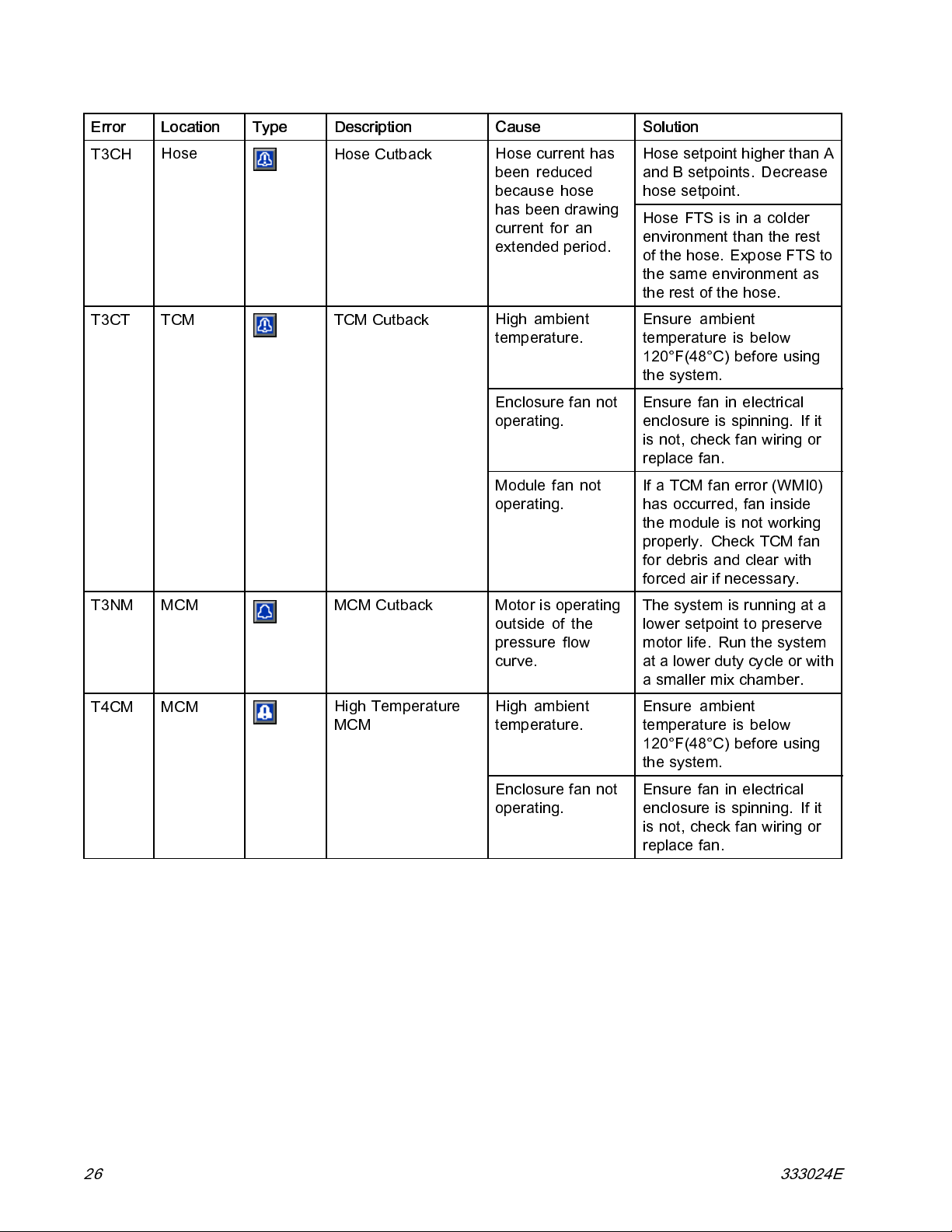
T3CH
T3CT TCM TCM Cutback
Hose
Hose Cutback
Cause Solution
Hose current has
been reduced
because hose
has been drawing
current for an
extended period.
High ambient
temperature.
Enclosure fan not
operating.
Module fan not
operating.
Hose setpoint higher than A
and B setpoints. Decrease
hose setpoint.
Hose FTS is in a colder
environment than the rest
of the hose. Expose FTS to
thesameenvironmentas
therestofthehose.
Ensure ambient
temperature is below
120°F(48°C) before using
the system.
Ensure fan in electrical
enclosure is spinning. If it
is not, check fan wiring or
replace fan.
If a TCM fan error (WMI0)
has occurred, fan inside
the module is not working
properly. Check TCM fan
for debris and clear with
forced air if necessary.
T3NM
T4CM MCM
MCM
MCM Cutback
High Temperature
MCM
Motor is operating
outside of the
pressure flow
curve.
High ambient
temperature.
Enclosure fan not
operating.
The system is running at a
lower setpoint to preserve
motor life. Run the system
at a lower duty cycle or with
a smaller mix chamber.
Ensure ambient
temperature is below
120°F(48°C) before using
the system.
Ensure fan in electrical
enclosure is spinning. If it
is not, check fan wiring or
replace fan.
26 333024E
Page 27
Troubleshooting
Error Location Type Description
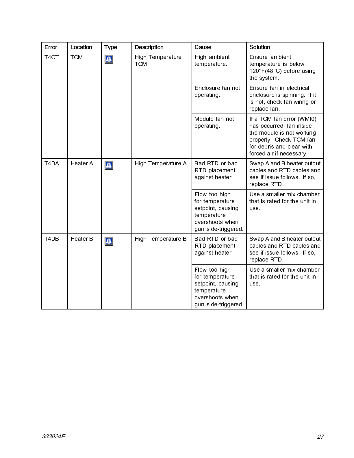
T4CT TCM
T4DA Heater A High Temperature A
High Temperature
TCM
Cause Solution
High ambient
temperature.
Enclosure fan not
operating.
Module fan not
operating.
Bad RTD or bad
RTD placement
against heater.
Flow too high
for temperature
setpoint, causing
temperature
overshoots when
gun is de-triggered.
Ensure ambient
temperature is below
120°F(48°C) before using
the system.
Ensurefaninelectrical
enclosure is spinning. If it
is not, check fan wiring or
replace fan.
If a TCM fan error (WMI0)
has occurred, fan inside
themoduleisnotworking
properly. Check TCM fan
for debris a nd clear with
forced air if necessary.
Swap A and B hea ter output
cables and RTD cables and
see if issue follows. If so,
replace RTD.
Use a smaller mix chamber
that is rated for the unit in
use.
T4DB Heater B High Temperature B
Bad RTD or bad
RTD placement
against heater.
Flow too high
for temperature
setpoint, causing
temperature
overshoots when
gun is de-triggered.
Swap A and B hea ter output
cables and RTD cables and
see if issue follows. If so,
replace RTD.
Use a smaller mix chamber
that is rated for the unit in
use.
333024E
27
Page 28
Troubleshooting
Error Location Type Description
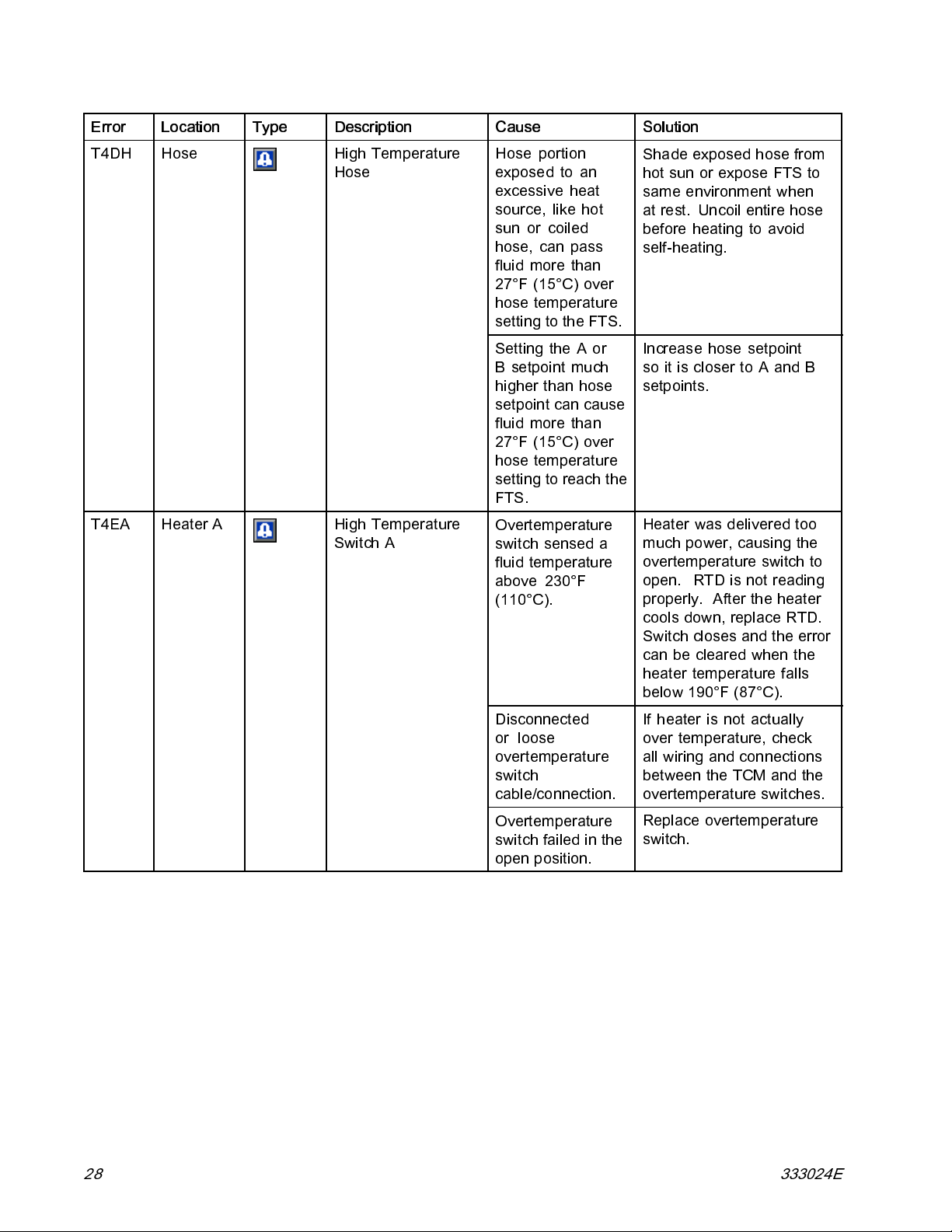
T4DH Hose High Temperature
Hose
T4EA Heater A High Temperature
Switch A
Cause Solution
Hose portion
exposed to an
excessive heat
source, like hot
sun or coiled
hose, can pass
fluid more than
27°F (15°C) over
hose temperature
settingtotheFTS.
Setting the A or
B setpoint much
higher than hose
setpoint can cause
fluid more than
27°F (15°C) over
hose temperature
settingtoreachthe
FTS.
Overtemperature
switch sensed a
fluid temperature
above 230°F
(110°C).
Shade exposed hose from
hot sun or expose FTS to
same environment when
at rest. Uncoil entire hose
before hea tin g to avoi d
self-heating.
Increase hose setpoint
so it is closer to A and B
setpoints.
Heater was delivered too
much power, causing the
overtemperature switch to
open. RTD is not reading
properly. After the heater
cools down, replace RTD.
Switch closes and the error
canbeclearedwhenthe
heater temperature falls
below 190°F (87°C).
Disconnected
or loose
overtemperature
switch
cable/connection.
Overtemperature
switch failed in the
open position.
If heater is not actually
over temperature, check
all wiring and connections
between the TCM and the
overtemperature switches.
Replace overtemperature
switch.
28 333024E
Page 29
Troubleshooting
Error Location Type Description
T4EB Heater B High Temperature
Switch B
T4NM MCM High Temperature
Motor
Cause Solution
Overtemperature
switch sensed a
fluid temperature
above 230 °F
(110°C).
Disconnected
or loose
overtemperature
switch
cable/connection.
Overtemperature
switch failed in the
open position.
Cooling fan is not
operating properly.
Heater was delivered too
much power, causing the
overtemperature switch to
open. RTD is not reading
properly. After the heater
cools down, replace RTD.
Switch closes and the error
canbeclearedwhenthe
heater temperature falls
below 190°F (87°C).
If heater is not actually
over temperature, check
all wiring and connections
between the TCM and the
overtemperature switches.
Replace overtemperature
switch.
Check to see that the motor
fan is moving. Measure
voltagetofan.Thereshould
be24VDC.
If no voltage is measured,
check fan wiring. If the
fan has voltage but is not
moving, replace fan.
If necessary use an air hose
to blow out around the fan
housings and remove any
built-up debris.
Disconnected
or loose motor
temperature cable.
High ambient
temperature.
Bad electric motor. Replace electric motor.
T6DA Heater A Sensor Error A
333024E 29
Disconnected or
loose RTD cable or
connection.
Bad RTD.
Verify wiring between th e
motor temperature sensor
and the MCM.
Ensure ambient
temperature is below
120°F(48°C) before using
the system.
Check all wiring and
connection to RTD.
Switch the RTD with
another and see if the error
messagefollowstheRTD.
Replace RTD if the error
follows the RTD.
Page 30
Troubleshooting
Error Location Type Description
T6DB Heater B
T6DH Hose
Sensor Error B
Sensor Error Hose
Cause Solution
Disconnected or
loose RTD cable or
connection.
Bad RTD.
Disconnected or
shorted RTD cable
in hose or bad FTS.
Check all wiring and
connection to RTD.
Switch the RTD with
another and see if the error
messagefollowstheRTD.
ReplaceRTDiftheerror
follows the RTD.
Expose each hose RTD
connection to check and
retighten any loose con-
nector. Measure hose RTD
cable and FTS continui ty .
See Repair Heated Hose,
page 63.OrderRTDTest
kit 24N365 for measure-
ment.
Disconnect hose RTD and
usemanualhosemodeto
finish job until repair can be
completed.
T6DT
TCM
Sensor Error TCM
Shorted RTD cable
in hose or FTS.
Shorted A or B
Heater RTD
Expose each hose RTD
connection to check for
exposed and shorted RTD
wires. Measure hose RTD
cable and FTS continui ty .
See Repair Heated Hose,
page 63.OrderRTDTest
kit 24N365 for measure-
ment.
Disconnect hose RTD and
usemanualhosemodeto
finish job until repair can be
completed.
If the error still occurs with
the hose FTS unplugged,
one of the heater RTDs
is bad. Unplug the A or
B RTD from the TCM. If
unplugging an RTD fixes
the T6DT error, replace the
RTD.
30 333024E
Page 31

Troubleshooting
Error Location Type Description
T8DA Heater A No Temperature
Rise A
T8DB Heater B No Temperature
Rise B
Cause Solution
Bad RTD or bad
RTD placement
against heater.
Bad heater rod or
loose heater wire.
Started spraying
before heater
reached operating
temperature.
Bad RTD or bad
RTD placement
against heater.
Swap A and B hea ter output
cables and RTD cables and
see if issue follows. If so,
replace RTD.
Confirm resistance of
heater. Heater resistance
shouldbe9-12Ωfor10
kW systems and 6-8 Ω
for 15 kW systems. If out
of tolerance, check for
loose heater rod wire(s).
Reconnect wires or replace
heater rod if necessary.
Wait until operating
temperature has b een
reached before spraying or
recirculating.
Swap A and B hea ter output
cables and RTD cables and
see if issue follows. If so,
replace RTD.
T8DH Hose No Temperature
Rise Hose
V1CM MCM Low Voltage MCM
Bad heater rod or
loose heater wire.
Started spraying
before heater
reached operating
temperature.
Started spraying
before heater
reached operating
temperature.
Loose/bad
connection or
tripped circuit
breaker.
Low incoming line
voltage.
Confirm resistance of
heater. Heater resistance
shouldbe9-12Ωfor10
kW systems and 6-8 Ω
for 15 kW systems. If out
of tolerance, check for
loose heater rod wire(s).
Reconnect wires or replace
heater rod if necessary.
Wait until operating
temperature has b een
reached before spraying or
recirculating.
Wait until operating
temperature has b een
reached before spraying or
recirculating.
Check wiring for loose
connection or tripped circuit
breaker.
Measure voltage at circuit
breaker and ensure voltage
is greater than 195 VAC.
333024E 31
Page 32

Troubleshooting
Error Location Type Description
V1IT
V2IT
V2MA
V2MB
TCM
TCM
TCM
TCM
Low Voltage CAN Bad 24 VDC power
Low Voltage CAN Bad 24 VDC power
Low Voltage A
Low Voltage B
Cause Solution
Check voltage of power
supply.
supply.
Loose connection
or tripped circuit
breaker.
Low incoming line
voltage.
Loose connection
or tripped circuit
breaker.
Low incoming line
voltage.
supply. Voltage should
be 23-25 VDC. If out of
tolerance, replace power
supply.
Check voltage of power
supply. Voltage should
be 23-25 VDC. If out of
tolerance, replace power
supply.
Check wiring for loose
connection or tripped circuit
breaker.
Measure voltage at circuit
breaker and ensure voltage
is greater than 195 VAC.
Check wiring for loose
connection or tripped circuit
breaker.
Measure voltage at circuit
breaker and ensure voltage
is greater than 195 VAC.
V2MH
V3IT
V3MA
TCM
TCM
TCM
Low Voltage Hose
High Voltage CAN Bad 24 VDC power
High Voltage A Incoming l ine
Loose connection
or tripped circuit
breaker.
Low incoming line
voltage.
supply.
voltage is too high.
Check wiring for loose
connection or tripped circuit
breaker.
Measure voltage at circuit
breaker and ensure voltage
is greater than 195 VAC.
Check voltage of power
supply. Voltage should
be 23-25 VDC. If out of
tolerance, replace power
supply.
Ensure incoming system
power is wired properly.
Verify voltage at each circuit
breaker is between 195 and
264 VAC.
32 333024E
Page 33

Troubleshooting
Error Location Type Description
V3MB
V3MH
V4CM MCM High Voltage MCM Incoming line
V4IT
V4MA
TCM
TCM
TCM
TCM
High Voltage B Incoming line
High Voltage Hose Incoming line
High Voltage CAN Bad 24 VDC power
High Voltage A Incoming line
Cause Solution
voltage is too high.
voltage is too high.
voltage is too high.
supply.
voltage is too high.
Ensure incoming system
power is wired properly.
Verify voltage at each circuit
breaker is between 195 and
264 VAC.
Ensure incoming system
power is wired properly.
Verify voltage at each circuit
breaker is between 195 and
264 VAC.
Ensure incoming system
power is wired properly.
Verify voltage at each circuit
breaker is between 195 and
264 VAC.
Check voltage of power
supply. Voltage should
be 23-25 VDC. If out of
tolerance, replace power
supply.
Ensure incoming system
power is wired properly.
Verify voltage at each circuit
breaker is between 195 and
264 VAC.
V4MB
V4MH
TCM
TCM
High Voltage B Incoming line
voltage is too high.
High Voltage Hose Incoming line
voltage is too high.
Ensure incoming system
power is wired properly.
Verify voltage at each circuit
breaker is between 195 and
264 VAC.
Ensure incoming system
power is wired properly.
Verify voltage at each circuit
breaker is between 195 and
264 VAC.
333024E 33
Page 34

Troubleshooting
Error Location Type Description
WBC0 MCM Software Version
Error
WMI0
WSUX USB Configuration Error
WXUD ADM
WXUU ADM
TCM
TCM Fan Error Fan inside TCM
USB
USB Download Error
USB Upload Error Custom language
Cause Solution
Incorrect software
version.
MCM does not
have line voltage.
is not operating
properly.
Avalid
configuration file
can't be found for
the USB.
Log download
failed.
filefailedtoupload.
Insert a system token into
the ADM module and cycle
the power. Wait until the
upload is complete before
removing the token.
If V1CM also exists, see
troubleshooting for V1CM.
The software version
cannot be read if the MCM
does not have line voltage.
Check for debris in the TCM
fan and clear with forced air
if necessary.
Inset a system token into
the ADM and cycle power.
Wait until the lights on the
USB port stop flashing
before removing token.
Backup and reformat the
USB drive. Retry download.
Perform normal USB
download and use the new
disptext.txtfiletouploadthe
custom language.
34 333024E
Page 35

System
Before performing any troubleshooti ng proc edu res:
1. Relieve Pressure. See Pressure Relief Procedure, page 42.
2. Turn main power switch OFF.
3. Allow equipment to cool.
Troubleshooting
Problem
Reactor ADM does not turn on.
Electric motor does not operate.
Electric motor runs erratically. Failed motor bearing. Replace motor, see
No power.
Failed 24 V power supply. Replace power supply.
Failed surge protector. Replace surge protector.
Loose connections.
Tripped circuit breaker (CB02). Reset breaker, see Repair Circuit
Shorted windings.
Cause Solution
Turn main power switch ON.
Check MCM connection 13.
Breaker Module, page 54.Check
240VAC at output of breaker.
Replace motor, see
Repair Electric Motor, page 53.
Repair Electric Motor, page 53.
333024E 35
Page 36

Troubleshooting
Problem Cause Solution
Cooling fans not working.
Pump output low.
Fluidleakinpumppackingnut
area.
No pressure on one side.
Loose wire.
Fan blade obstructed. Remove obstruction.
Defective fan. Replace. See
Obstructed fluid hose or gun; fluid
hose ID too small.
Worn piston valve or intake valve
in displacement pump.
Pressure setpoint too high. Reduce setpoint and output will
Worn throat seals.
Fluid leaking from heater inlet
rupture disk (372).
Check. See
Electrical Schematics, page 89.
Replace Motor Fan, page 56.
Open, clear; use hose with larger
ID.
Seepumpmanual.
increase.
Replace. See pump manual.
Check if heater and PRESSURE
RELIEF/SPRAY valve (SA or SB)
are plugged. Clear. Replace
rupture disk (372) with a new one;
do not replace with a pipe plug.
36 333024E
Page 37

Hose Heat System
Before performing any troubleshooti ng proc edu res:
1. Relieve Pressure. See Pressure Relief Procedure, page 42.
2. Turn main power switch OFF.
3. Allow equipment to cool.
Problem Cause Solution
Troubleshooting
Hose heats b
than usual o
temperatu
Hose does not maintain
temperature while spraying.
ut heats slower
r it does not reach
re.
Ambient tem
FTS failed or not installed correctly. Check FTS, see Check RTD
Low supply voltage.
A and B setpoints too low. Increase A and B setpoints.
Ambien
Flow too high. Use smaller mix chamber.
Hose was not fully preheated. Wait for hose to heat to correct
Low supply voltage.
perature is too cold.
t temperature is too cold.
Relocate ho
or recircul
the hose.
Cables and FTS, page 63.
Verify line voltage. Low line
voltage significantly reduces
power available to the hose heat
system, affecting longer hose
lengths.
Hose is designed to maintain
temperature, not to increase it.
Increa
increa
keep it
Decrease pressure.
temperature before spraying.
Verify line voltage. Low line
voltage significantly reduces
power available to the hose heat
system, affecting longer hose
lengths.
sestoawarmerarea
ate heated fluid through
seAandBsetpointsto
se fluid temperature and
steady.
se temperature exceeds
Ho
tpoint.
se
333024E 37
nd/or B heaters are overheating
Aa
terial.
ma
aulty FTS connections.
F
Ambient temperature is too high.
Check primary heaters for either
a RTD problem or a failed
element attached to RTD, see
Electrical Schematics, page 89.
erify that all FTS connections are
V
nug and that pins of connectors
s
re clean. Unplug and re-plug
a
TD wires, cleaning off any debris.
R
Cover hoses or move to a location
with a lower ambient temperature.
Page 38

Troubleshooting
Problem
Erratic hose temperature.
Hose does not heat.
Cause Solution
Faulty FTS connections. Verify that all FTS connectio ns are
snug and that pins of connectors
are clean. Unplug and re-plug
FTS wires along length of hose,
cleaning off any debris.
FTS not installed correctly. FTS sh ould be installed close to
endofhoseinsameenvironment
as gun. Verify FTS installation,
see Repair Fluid Temperature
Sensor (FTS), page 64.
FTS failed. Check FTS, see Repai r Fluid
Temperature Sensor (FTS), page
64.
FTS not installed correctly. FTS sh ould be installed close to
endofhoseinsameenvironment
as gun. Verify FTS installation,
see Repair Fluid Temperature
Sensor (FTS), page 64.
Loose hose electrical connections. Check connections. Repair as
necessary.
Circuit breakers tripped. Reset breakers (CB01 ), see
Repair Circuit Breaker Module,
page 54.
Hose zone not turned on. Turn on hose heat zone.
A and B temperature setpoints too
low.
Check. Increase if necessary.
38 333024E
Page 39

Troubleshooting
Problem
Hoses near Reactor are warm, but
hoses downstream are cold.
Low hose heat.
Cause Solution
Shorted connection or failed hose
heating element.
A and B temperature setpoints too
low.
Hose temperature setpoint too
low.
Flow too high. Use smaller mix chamber.
Low current; FTS not installed. Install FTS, see operation manual.
Hose heat zone not turned on long
enough to reach setpoint.
Loose hose electrical connections.
With power off, check the hose
resistance with and without the
whip hose attached. With the whip
hose attached, the reading should
belessthan3ohm.Withoutthe
whip hose attached, the reading
shouldbeOL(openloop).See
Check Hose Heat Connectors,
page 63.
Increase A and B setpoints. Hose
designed to maintain temperature,
not increase temperature.
Check. Increase if necessary to
maintain heat.
Decrease pressure.
Allow hose to heat up, or preheat
fluid.
Check connections. Repair as
necessary.
Ambient temperature is to low Relocate hoses to a warmer area
or increase A and B setpoints.
333024E 39
Page 40

Troubleshooting
Primary Heater
Before performing any troubleshooting procedures:
1. Relieve Pressure. See Pressure Relief Procedure, page 42.
2. Turn main power switch OFF.
3. Allow equipment to cool.
Problems
Try the recommended solutions in the order given for each problem, to avoid unnecessary repairs. Also,
determine that all circuit breakers, switches, and controls are properly set and wiring is correct before
assuming there is a problem.
Problem
Primary Heater(s) does not heat.
Control of primary heat is
abnormal; high temperature
overshoots (T4DA, T4DB) occurs
intermittently.
Cause Solution
Heat turned off.
Temperature control alarm.
Signal failure from RTD. Signal failure from RTD.
Dirty RTD connections. Exami ne RTD cable s conn ected
RTD not contacting heater
element.
Failed heater element.
Signal failure from RTD. See (T6DA, T6DB), Error Codes.
Turn on heat zones.
Check ADM for error codes.
to TCMs. Confirm RTDs are
not plugged into opposite heat
zone. Unplug and re-plug RTD
connectors. Unplug and re-plug
RTD connectors. Ensure RTD tip
contacts the heater element.
Loosen ferrule nut, push in RTD
so tip contacts heater element.
Holding RTD tip against heater
element, tighten ferrule nut 1/4
turn past tight.
See
Replace Heater Element, page 59.
40 333024E
Page 41

Graco InSite
Troubleshooting
Problem
No module status LEDs are
illuminated.
Has not identified GPS location
(green module status LED
flashing).
Has not established cellular
connection (orange module status
LED flashing).
Cannot view data for my unit(s) on
website.
Temperature data not displayed
on website.
Hose zone temperature data not
displayed on website.
Pressure data not displayed on
website.
Cause Solution
No power to cellular module.
Still identifying location. Wait a few minutes for the unit to
Unable to identify location. In a
location where GPS lock cannot
occur. Buildings and warehouses
often prevent GPS locks.
Still establishing cellular
connection.
Unable to establish cellular
connection.
Graco InSite unit has not been
activated.
Reactor temperature
measurement is not working.
The RTD or thermocouple is not
correctly installed on the hose or
is broken.
Reactor pressure measurement is
not working.
Turn Reactor ON.
Ensure unit is properly installe d.
Verify24Vatoutputofthepower
supply.
MakesuretheM8,4–pintoM12,
8–pin cable is instal le d betwe en
cellular module and power supply.
identify the location.
Move system to a location with a
clear view of the sky.
Use extension cable 16X521 and
move cellular module to a location
with a clear view of the sky.
Wait a few minutes for the unit to
establish the connection.
Move system to a location with
cellular service to establish cellular
connection.
Use extension cable 16X521 and
move cellular module to a location
with a clear view of the sky.
Activate unit. See Registering
and Activating the Graco InSite
section.
See S ys tem troubleshooti ng
section.
See RTD or Thermocouple repair
section.
See S ys tem troubleshooti ng
section.
333024E
41
Page 42

Pressure Relief Procedure
Pressure Relief Procedure
Follow the Pressure Relief Procedure
whenever you see this symbol.
This equipment stays pressurized until pressure
is manually relieved. To help prevent serious
injury from pressurized fluid, such as skin injection,
splashing fluid and moving parts, follow the
Pressure Relief Procedure when you stop spraying
and before cleaning, checking, or servicing
equipment.
The Fusion AP gun is shown.
1. Relieve pressure in gun and perform gun
shutdown procedure. See gun manual.
2. Close gun fluid inlet valves A and B.
4. Route fluid to w aste containers or supply tanks.
Turn PRESSURE RELIEF/SPRAY valves (SA,
SB) to PRESSURE RELIEF/CIRCULATION
. Ensure gauges drop to 0.
5. Engage gun piston safety lock.
6. Disconnect gun air line and remove gun fluid
manifold.
3. Shut off feed pumps and agitator, if used.
42
333024E
Page 43

Shutdown
Shutdown
Shutdown system to avoid electric shock. All
electrical wiring must be done by a qualified
electrician and comply with all local c odes and
regulations. To help prevent serious injury from
pressurized fluid, such as skin injection, splashing
fluid and moving parts, follow the Pressure Relief
Procedure when you stop spraying and before
cleaning, checking, or servicing equipment.
NOTICE
Proper system setup, startup, and shutdown
procedures are critical to electrica l equipment
reliability. The following procedures ensure steady
voltage. Failure to follow these procedures will
cause voltage fluctuations that can damage
electrical equipment and void the warranty.
4. Press to park the Component A Pump. The
park operation is c omplete when green dot goes
out. Verify the park operation is complete before
moving to next step.
5. Press to deactivate the system.
6. Turn off the air compressor, air dryer, and
breathing air.
1. Press to stop the pumps.
2. Turn off all heat zones.
3. Relieve pressure. See
Pressure Relief Procedure, page 42.
7. Turn main power switch OFF.
To prevent electric shock do not remove any
shrouds or open the electri cal enclosure door.
333024E 43
Page 44

Shutdown
8. Close all fluid supply valves. 9. Engage gun piston safety lock then close fluid
inlet valves A and B.
Fusion Probler
44
333024E
Page 45

Flushing
Flushing
To avoid fire and explosion:
• Flush equipment only in a well-ventilated area.
• Do not turn on heaters until fluid lines are clear
of solvent.
• Flush out old fluid with new fluid, or flush out old
fluid with a compatible solvent before introducing
new fluid.
• Use the lowest possible pressure when flushing.
• All wetted parts are compatible with com mon
solvents. Use only moisture-free solvents.
To flush feed hoses, pumps, and heaters
separately from heated hoses, set PRESSURE
RELIEF/SPRAY valves (SA, SB) to PRESSURE
RELIEF/CIRCULATION
lines (N).
To flush entire system, circulate through gun fluid
manifold (with manifold removed from gun).
To prevent moisture from reacting with
isocyanate, always leave the system filled
with a moisture-free plasticizer or oil. Do not
use water. Never leave the system dry. See
Important Isocyanate Information, page 7 .
.Flushthroughbleed
333024E 45
Page 46

Repair
Repair
Repairing this equipment requires access to parts
that may cause electric shock or other serious
injury if work is not performed properly. Be sure to
shut off all power to equipment before repairing.
Before Beginning Repair
NOTICE
Proper system setup, startup, and shutdown
procedures are critical to electrical equipment
reliability. The following procedures ensure s tead y
voltage. Failure to follow these procedures will
cause voltage fluctuations that can damage
electrical equipment and void the warranty.
1. Flush if necessary. See Flushing, page 45.
1. Close the fluid inlet valve on the y-strainer inlet
andshutofftheappropriatefeedpump.This
prevents material from being pumped while
cleaning the screen.
2. Place a container under the strainer base to catch
drain off when removing the strainer plug (C).
3. Remove the screen (A) from the strainer
manifold. Thoroughly flush the screen with
compatible solvent and shake it dry. Inspect the
screen. No more than 25% of the mesh should
be restricted. If more than 25% of the mesh is
blocked, replace the screen. Inspect the o—rin g
(B) and replace as required.
4. Ensure the pipe plug (D) is screwed into the
strainer plug (C). Install the strainer plug with the
screen (A) and o—ring (B) in place and tighten.
Do not overtighten. Let the gasket make the seal.
5. Open the fluid inlet valve, ensure that there are
no leaks, and wipe the equipment clean. Proceed
with operation.
2. See Shutdown, page 43.
Flush Inlet Strainer Screen
The inlet strainers filter out particles that can plug the
pump inlet check valves. Inspect the screens daily as
part of the startup routine, and clean as required.
Isocyanate can crystallize from moisture
contamination or from freezing. If the chemicals used
are clean and proper storage, transfer, and operating
procedures are followed, there should be minimal
contamination of the A-side screen.
Note
Clean the A-side screen only during
daily startup. This minimizes moisture
contamination by immedia tel y flushing
out any isocyanate residue at the start of
dispensing operations.
Figure 1
46 333024E
Page 47

Repair
Change Pump Lubricant
Check the condition of the ISO pump lubricant daily.
Change the lubricant if it becomes a gel, its color
darkens, or it becomes diluted with isocyanate.
Gel formation is due to moisture absorption by the
pump lubricant. The interval between chan ges
depends on the environment in which the equipment
is operating. The pump lubrication system minimizes
exposure to moisture, but some contamination is st ill
possible.
Lubricant discoloration is due to continual seepage of
small amounts of isocyanate past the pump packings
during operation. If the packings are operating
properly, lubricant replacement due to discoloration
should not be necessary more often than every 3 or
4weeks.
To change pump lubricant:
1. Follow Pressure Relief Procedure, page 42.
2. Lift the lubricant reservoir (R) out of the bracket
and remove the container from the cap. Holding
the cap over a suitable containe r, remov e the
check valve and allow the lubricant to drain.
Reattach the check valve to the inlet hose.
4. When the reservoir is flushed clean, fill with fresh
lubricant.
5. Thread the rese rvoir onto the cap assembly and
place it in the bracket.
6. The lubrication system is ready for operation. No
priming is required.
Pump Lubrication System
Figure 2
3. Drain the reservoir and flush it with clean
lubricant.
333024E
47
Page 48

Repair
Remove Pump
Pump rod and connecting rod move during
operation. Moving parts can cause serious injury
such as pinching or amputation. Keep hands and
fingers away from connecting rod during operation.
Note
See manual 309577
instructions.
1. Press
2. Turn off heat zones.
3. Flush pump.
4. Press
5. Press
6. Turn main power switch off.
7. S hu t off both feed pumps. Close all fluid supply
valves.
to stop the pumps.
to park the pumps in the down position.
to deactivate the system.
for pump repair
8. Route fluid to w aste containers or supply tanks.
Turn PRESSURE RELIEF/SPRAY valves (SA,
SB) to PRESSURE RELIEF/CIRCULATION
. Ensure gauges drop to 0.
48 333024E
Page 49

Note
Use drop cloth or rags to protect Reactor
and surrounding areas from spills.
Note
Steps9–11applytopumpA.To
disconnect pump B, go to steps 12 and
13.
9. Disconnect fittings at fluid inlet (C) and outlet (D).
Also disconnect steel outlet tube from heater
inlet.
10. Disconnect
(U) from wet
tubes (T). Remove both tube fittings
-cup.
11. Loosen locknut (G) by hitting firmly with a
non-sparking hammer. Unscrew pump far
enough to expose rod retaining pin. Push
retaining wire clip up. Push pin out. Continue
unscrewing pump.
Pump B
Figure 4
1
2
3
Repair
Flat side faces up.
Lubricat
Pump top threads must be nearly flush with
bearing face (N).
e threads with ISO oil or grease.
Pump A
Figure 3
Flat side faces up.
1
Lubricate threads with ISO oil or grease.
2
Pump top threads must be nearly flush with
3
bearing face (N).
Note
Steps 12 and 13 apply to pump B.
12. Disconnect fluid inlet (C) and outlet (D). Also
disconnect steel outlet tube from heater inlet.
13. Push retaining wire clip (E) up. Push pin (F)
out. Loosen locknut (G) by hitting firmly with a
non-sparking hammer. Unscrew pump.
Install Pump
Note
Steps 1–5 apply to pump B. To reconnect
pump A, proceed to step 6.
1. Ensure locknut (G) is s crewed on pump with
flat side up. Screw pump into bearing housing
(M) until pin holes align. Push pin (F) in. Pull
retaining wire clip (E) down. See Fig. 4 for view
and assembly notes.
2. Continue screwing pump into housing until fluid
outlet (D) is aligned with steel tube and top
threads are +/- 1/16 in. (2 mm) of bearing face
(N).
3. Tighten locknut (G) by hitting firmly with a
non-sparking hammer.
4. Reconnect fluid inlet (C) and outlet (D).
5. Go to step 13.
Note
Steps 6–12 apply to pump A o nly.
6. Ensure star-shaped locknut (G) is screwed on
pump with flat side up. Carefully twist and extend
displacement rod 2 in. (51 mm) above wet-cup.
333024E 49
Page 50

Repair
11. Apply thin film of TSL to barbed fittings. Usin g
two hands, support tubes (T) while pushing
straight onto barbed fittings. Secure each tube
withawiretiebetweentwobarbs.
Note
Do not let tubes kink or buckle.
12. Reconnect fluid inlet (C).
13. Purge air and prime the system. See Reactor
operation manual.
Repair Drive Housing
Removal
Figure 5
7. Start threading pump into bearing housing (M).
When pin holes align, insert pin. Pull retaining
wire clip down.
8. Continue threading pump into bearing housing
(M) until top threads are +/- 1/16 in. (2 mm) of
bearing face (N). Ensure that barbed fittings at
wet-cupflushportsareaccessible.
9. Connect component A outlet tube loosely at
pump and at heater. Line up tube, then tighten
fittings securely.
10. Tighten star-shaped locknut (G) by hitting firmly
with a non-sparking hammer.
1. Press to stop the pumps.
2. Turn off heat zones.
3. Flush pump.
4. Press
5. Press
6. Turn main power switch off.
to park the pumps in the down position.
to deactivate the system.
50 333024E
Page 51

Repair
7. Perform Pressure Relief Procedure, page 42.
8. Remove the system frame from the floor and
L-brackets.
NOTICE
Do not drop gear cluster (104) when removing
drive housing (102). Gear cluster may stay
engaged in motor front end bell or drive
housing.
14. Remove screws (112, 119) and washers (114)
and pull drive housing (102) off motor (101).
Note
The A side drive housing includes cycle
counter switch (121). If replacing thi s
housing, remove screws (122) and
switch. Reinstall screws and switch on
new drive housing.
9. Remove two bolts and nuts and fold the electrical
enclosure backward.
10. Remove screws (21) and motor shroud (11).
Rest the motor shroud behind the motor without
straining the fan power cable.
Note
Examine bearing housing (103) and
connecting rod (105). If these parts need
replacing, first remove the pump (106),
see Remove Pump, page 48.
11. Remove cover (60) and screws (21).
12. Remove cycle counter (121) from housing by
removing screw (122).
13. Disconnect pump inlet and outlet lines. Remove
screws (113), washers (115), and bearing
housing (103).
Figure 6
333024E 51
Page 52

Repair
Installation
1. Apply heavy duty extreme pressure grease
liberally to washers (107, 108, 118), al l gears,
and inside drive housing (102).
2. Install one bronze washer (108) in drive housing,
then install steel washers (107, 118) as shown.
3. I ns tall second bronze washer (108) on gear
cluster (104) and insert gear cluster in drive
housing.
Note
Drive housing crankshaft must be in line
with crankshaft at other end of motor.
4. Push drive housing (102) onto motor (101).
Install screws (112) and washers (114).
Note
If bearing housing (103), conn ec tin g rod
(105), or pump (106) were removed,
reassemblerodinhousingandinstall
pump, see Install Pump, page 49 .
5. Route cycle counter switch cable (121) around
the motor fan and reattach to housing (102) with
screws (122).
6. In st all bearing housing (103), screws (113), and
washers (114). Pumps must be in phase (both at
same position in stroke).
7. Install cover (60) and screws (21).
8. Install motor shield (11) and screws (21).
Figure 7
52 333024E
Page 53

Repair Electric Motor
Removal
NOTICE
Be careful not to drop or damage the motor. The
motor is heavy and may require two people to lift.
1. Remove the system frame from the floor and
L-brackets.
Repair
2. Remove drive housing and pump assemblies.
See Repair Drive Housing, page 50.
3. Disconnect electric motor (101) power cable from
port #15 on the MCM. Remove connector by
loosening four terminal screws.
4. Remove motor shroud (11). Rest the motor
shroud assembly behind the motor without
straining the fan power cable.
5. Disconnect over temperature cable from port
#2 on MCM. Cut tie wraps around harness to
remove cable.
6. Remove four screws (25) holding motor (101) to
bracket. Lift motor off unit.
Installation
1. Place motor on unit. Thread motor
cables into conduit as before. See
Electrical Schematics, page 89.
2. Fasten motor with screws (25) until screws are
fully threaded in frame. Do not tighten screws
until drive housing and pumps are connected to
the motor.
3. Install drive housing and pump assemblies, see
Installation, page 52.
4. Route motor (101) power cord from motor
through conduit and connect to port #15 on
MCM. Route over temperature cable up from
motor and connect to port #2 on MCM. Insert
cablesinconduitandusetiewrapstosecurethe
conduit together.
5. Con nec t motor shroud assembly to motor (101).
6. Install drive housing covers and motor cover.
7. Return to service.
333024E 53
Page 54

Repair
Repair Circuit Breaker Module
1. See Before Beginning Repair, page 46.
2. Using an ohmmeter, check for continuity across
circuit breaker (top to bottom). If no continuity,
trip break er, reset, and retest. If s ti ll no continui ty ,
replace breaker as follows:
a. Refer to Electrical Schematics, page 89, and
circuit breaker table.
b. Fo ll ow Shutdown instructions . See
Shutdown, page 43.
c. Refer to circuit breaker identification table
and electrical diagrams in Reactor repair
manual.
d. L oos en two screws connecting wires and bus
bar to circuit breaker that will be replaced.
Disconnect wires.
new circuit breaker. Insert wires and tighten
down all screws.
Figure 8
Circuit Breakers
Circuit Breakers
Ref. Size Component
CB01
CB02
CB03
CB04
CB05 40 A Hose Heat Transformer
50 A Heated Hose
20 A
40 A
40 A
Motor Control Module
(MCM)
ISO Heater
RES Heater
e. Pull locking tab out 1/4 in. (6mm) and pull
circuit breaker away from the din rail. Install
54 333024E
Page 55

Repair
Replace Fluid Inlet Sensor
Note
For Elite models only.
1. Perform Shutdown, page 43.
2. Perform Pressure Relief Procedure, page 42.
3. Di sc onnec t inlet sensor cable from the fl ui d inlet
assembly. Inspect cable for dam age and replace
if necessary. See El ectrical Schematics, page 89.
5. Replace sensor (602).
Replace Pressure Transducers
1. Perform Shutdown, page 43.
2. Perform Pressure Relief Procedure, page 42.
3. Di sc onnec t transducer cables (405) from #6 and
#7 connectors on the MCM.
4. Remove wire ties constraining transducer cable
and remove cable from cabinet.
5. Install o-ring (416) on new transducer (405).
6. Ins ta ll transducer in manifold. Mark end of cable
with tape (red=t rans duce r A, blue=transducer B).
7. Route new cable into cabinet and thread into
bundle as before. Attach cable ties to bundle
as before.
8. Con nec t A side pres su re transducer cable
to MCM port #6. Connect B side pressure
transducer cable to MCM port #7.
Figure 9 Fluid Inlet Sensor
4. To replace sensor cable:
a. Open wire bundle and remove sensor cable.
b. Cut any wire ties and disconnect from MCM.
See Electrical Schematics, page 89.
NOTICE
To prevent dam ag e to cable, route and secure
cable in wire bundle with wire ties.
333024E 55
Page 56

Repair
Replace Fans
Shutdown system to avoid electric shock. To avoid
burns, do not perform maintenance on the fan until
the system has reached ambient temperature.
Replace Motor Fan
1. Perform Shutdown, page 43.
2. Open cabinet door and disconnect
fan cables from terminal blocks. See
Electrical Schematics, page 89.
3. Remove four screws (21) from motor cover (11).
If necessary, fold frame (1) to remove motor
cover (10). See Repair Drive Housing, page 50,
steps 1–10.
4. Cut tie wraps to remove cable.
5. Remove nuts (39), screws (22), washers (34)
and fan (32). Install new fan in reverse order.
Note
Ensure fan (32) blows onto motor.
Figure 10
56 333024E
Page 57

Replace Electrical Enclosure Fan
1. Perform Shutdown, page 43.
2. Open electrical enclosu re door (401). Loosen
four nuts (421) and remove fan (404).
3. Install new fan (404) in reverse order of
disassembly so that the fan blows out of the
electrical enclosure.
Repair
Figure 11
333024E 57
Page 58

Repair
Replace Transformer Fan
1. Perform Shutdown, page 43.
2. R emo ve four bolts (23) and shroud (10).
3. Remove bolt (20) on top of the heater junction
box (48).
4. Disconnect fan an d transformer connections
from terminal blocks. Connections are on left
side labeled: V+, V-, 1, 2, 3, and 4.
5. Remove four nuts (27) holding metal transformer
cover (8) to frame. Carefully remove cover while
slidingwiresthroughholeincover.
6. Remove four screws (23), washers (29), and fan
(32).
7. Install fan in reverse order.
Figure 12
58 333024E
Page 59

Repair
Repair Primary Heater
Replace Heater Element
1. Press to stop the pumps.
2. Turn off heat zo nes.
3. Flush pump.
4. Press
The park operation is complete when green dot
goes out. Verify the park operation is complete
beforemovingtonextstep.
to park the pumps in the down position.
8. Wait for heater to cool.
9. Remove four bolts (23) and shroud (10).
10. Remove screw (20) and lower din rail cover (48).
11. Disconnect heater wires:
a. A Side: Disconnect A side heater wires,
transformer, and transformer fan wires from
lower din rail (33).
5. Press to deactivate the system.
6. Turn
7. Relieve pressure. See
main power switch off.
Pressure Relief Procedure, page 42.
b. B Side: Disconnect B side heater wires and
remove lower din rail (33) from B side heater
(5).
12. Test heater wires with ohmmeter.
System
E-30 (10
kw)
E-XP2,
E-30 (15
kw)
To prevent a short circuit or lowering the
transformer life, do not splash fluid on
transformer. Cover transformer with a plastic
sheet or piece of cardboard.
Total
Heater
Wattage
10,200 2,550 18–21 per
15,300 2,550 18–21 per
Element
NOTICE
Ohms
element
element
333024E 59
Page 60

Repair
13. Remove nuts (27) and transformer cover
(8). Cover transformer with plastic sheet or
cardboard.
14. Disconnect overtemperature switches (209) from
cable.
15. Loosen ferrule nut (N). Remove RTD (212) from
heater housing. Do not remove adapter (206)
unless necessary. If adapter must be removed,
ensure that mixer (210) is out of the way when
replacing adapter.
16. Disconnect inlet and outlet fluid tubes from
heater.
17. Remove two bolts (23) and lift heater over
transformer.
18. Place heater block (201) in a vise. Use a wrench
to remove heater element (208).
19. Inspect element. It should be relatively smooth
and shiny. Replace element if there is a crusted,
burnt, ash-like material adhered to element, or
sheath shows pitting marks.
20. Install new heater element (208), holding mixer
(210) so it does not block RTD port.
21. Secure heater to frame with bolts (23).
22. Reinstall RTD (212),
Repair Primary Heater, page 59.
23. Reconnect cable to overtemperature switches
(209).
24. Reconnect wires to lower din rail. If necessary,
install lower din rail (33).
25. Install lower din rail cover (48).
Line Voltage
The heater outputs its rated wattage at 240 VAC.
Low line voltage will redu ce power available and the
heater will not perform at full capacity.
Figure 13
60 333024E
Page 61

Repair
Repair Overtemperature Switch
1. Perform Shutdown, page 43.
2. Wait for heaters to cool.
3. Remove heater cover (10).
4. Disconnect overtemperature switches (209) from
cable (46). Test across spade terminals with
ohmmeter.
a. If the resistance
the overtemperature switch needs to be
replaced. Go to step 5.
b. If the resistanceisapproximately 0 ohms,
inspect cable (46) to ensure it is not cut
or open. Reconnect the overtemperature
switch (209) and cable (46). Disconnect
cable from TCM. Test from pin 1 to 3 and
1 to 4. If resistance is not approximately 0,
and switches are 0. Replace cable in place
of original cable.
5. If switch fails test, remove screws. Discard failed
switch. Apply a thin layer of thermal compound
is not
approximately 0 ohms,
110009, install new switch in same location on
housing (201), and secure with screws (213).
Reconnect cables.
333024E 61
Page 62

Repair
Replace RTD
1. Perform Shutdown, page 43.
2. Wait for heater to cool.
3. Remove heater cover (10).
4. C ut cable ties around the woven wrap with the
RTD cable (212).
5. Disconnect RTD cable(212) from TCM (453).
6. Loosen ferrule nut (N). Remove RTD (212) from
heater housing (201), th en remove RTD housing
(H). Do not remove the adapter (206) unless
necessary. If adapter must be removed, ensure
that mixer (210) is out of the way when replacing
the adapter.
7. R emo ve RTD cable (212) from woven wrap.
8. Replace RTD (212).
a. Apply PTFE tape and thread sealant to male
pipe threads and tighten RTD housing (H)
into adapter (206).
b. P us h in RTD (212) so tip contacts heater
element (208).
c. Holding RTD (212) against heater element,
tightenferrulenut(N)3/4turnpast
finger-tight.
9. Route wires (S) as before through woven wrap
and reconnect RTD cable (212) to the TCM.
10. Replace heater shroud (10).
11. Follow startup instructions in the operation
manual. Turn on A and B heat simultaneously to
test.Temperaturesshouldriseatsamerate.If
one is low, loosen ferrule nut (N) and tighten RTD
housing (H) to ensure RTD ti p contacts element
(212) when ferrule nut (N) is retightened.
Figure 14
62 333024E
Page 63

Repair
Repair Heated Hose
Refer to the heated hose manual 309572 for hose
replacement parts.
Check Hose Heat Connectors
1. Perform Shutdown, page 43.
Note
Whip hose must be connected.
2. Disconnect hose connector (V) at Reactor, see
Fig. 13.
3. Using an ohmmeter, check between the
connectors (V). There should be continuity.
4. If hose fails test , retest at each length of hose,
including whip hose, until failure is isolated.
Check RTD Cables and FTS
1. Perform Shutdown, page 43.
2. Disconnect RTD cable (C) at Reactor.
3. Test with an ohmmeter between pins of cable
connector C.
Note
5. If the FTS is not reading properly at the end of
the hose, connect FTS directly to RTD cable (C)
at the manifold.
6. If the FTS reads properly at the manifold but
not at the end of the ho se, check cable (C)
connections. Verify they are tight.
Heated Hose
Figure 15
Do not touch outer ring with test probe.
Pins Result
3 to 1 approximately 1090
ohms
3 to 4 approximately 1090
ohms
1 to 4 0.2 - 0.4 ohms
2toany
4. Retest at each length of hose, including whip
hose, until failure is located.
infinity (open)
Note
To assist in taking readings, order RTD
Test Kit 24N365. Kit includes two cables:
one cable with a compatible female M8
connector and another cable with a male
M8 connector. Both cables have stripped
wire at the other end for easy test probe
access.
Pins / Wire Color
3 to 1 / brown to blue approximately 1090
/ blue to black
3to4
1to4/browntoblack 0.2-0.4ohms
2toany/N/A
Result
ohms
oximately 1090
appr
ohms
infinity (open)
333024E 63
Page 64

Repair
Repair Fluid Temperature Sensor (FTS)
Installation
The Fluid Temperature Sensor (FTS) is supplied with
the system. Install FTS between main hose and
whip hose. See Heated Hose manual 309572 for
instructions.
Figure 16
Test/Removal
1. Perform Shutdown, page 43.
2. Remove tape and protective covering from FTS.
Disconnect hose cable (F).
3. If FTS is not reading properly at the end of the
hose, see Check RTD Cables and FTS, page 63.
4. If FTS fails, replace FTS.
a. Disconnect air hoses (C,L) and electrical
connectors (D).
b. Di s co nnect FTS from whip hose (W) and
fluid hoses (A, B).
c. Remove ground wire (K) from ground screw
on underside of FTS.
d. Remove FTS probe (H) from component A
(ISO) side of hose.
64 333024E
Page 65

Repair
Transformer Primary Check
See Electrical Schematics, page 89.
1. Check wires and transformer:
a. See Shutdown, page 43.
b. Shut off CB05.
c. Use an ohmmeter to test for continuity
between terminals 2 and 4 of CB05. If there
is no continuity, check transformer.
2. Check transformer:
a. See Shutdown, page 43.
b. Remove lower shroud.
c. Locate the two smaller (10 AWG) wires,
labeled 1 and 2, coming out of transformer.
Trace these wires back to terminal blocks
TB15 and TB16.
d. Use an ohmmeter to test for continuity
between two wires; there should be
continuity.
Transformer Secondary Check
See Electrical Schematics, page 89.
1. Check wires and transformer:
a. Disconnect 7 pin green connector from TCM.
b. Use an ohmmeter to test for continuity
between terminals 6 an d 7 on the TCM 7 pin
green connector. There should be continuity.
If there is no continuity, check transformer.
c. Reconnect 7 pin green connector to TCM
2. Check transformer:
indicator on the ci rcu it breaker GREEN. Use
an ohmmeter to test for c ontinuity between
two transformer wires in terminal blocks
TB17andTB18;thereshouldbecontinuity.
c. Close the circuit breaker CB01.
Figure 17
d. Apply incoming power to system.
e. To verify voltage on the secondary leads
of the transformer, measure between the
terminals terminals 3 and 4 on TB17 and
TB18. Verify voltage is approximately 90
VAC for 240 VAC input.
f. SeetheDiagnosticRunScreenonthe
ADM. The Diagnostic Run Screen displays
the incoming (90 Vac) to the TCM “Hose
Voltage”. The diagnostic screen will show if
the circuit breaker has been tripped for the
incoming power to the TCM.
a. Remove lower shroud.
b. Locate the two larger (6 AWG) wires,
labeled 3 and 4, coming out of transformer.
Trace these wires back to TB17 and TB1 8.
Open circuit breaker CB01 to turn the col or
333024E 65
Page 66

Repair
Replace Transformer
1. Perform Shutdown, page 43.
2. R emo ve four bolts (23) and shroud (10).
3. Remove lower dinrail cover (48).
4. Disconnect fan and transformer connections
from terminal blocks. Connections are on left
side labeled: V+, V-, 1, 2, 3, and 4.
5. Remove four nuts (27) holding metal transformer
cover (8) t o frame. Carefully remove cover while
sliding wires through hole in cover.
6. Remove nuts (27) and transformer (17).
7. Install transformer (17) in reverse order.
Figure 18
66 333024E
Page 67

Replace Power Supply
1. Perform Shutdown, page 43.
2. Di sc onnec t input and output cables from
both sides of the power supply. See
Electrical Schematics, page 89.
3. Insert a flat head screw driver in the mounting
tab on the bottom of the power supply to remove
from the din rail.
Repair
Figure 20 Surge Protector
4. Install new power supply (535) in reverse order.
Figure 19 24 VDC Power Supply
Replace Surge Protector
1. Loosen connections on terminals 1 and 3 on
CB02.
Replace Advanced Display Module (ADM)
1. Loosen four screws (70) on inside of electrical
enclosure door (61). Lift up and pull out to
remove ADM (88).
2. Di sc onnec t CAN cable (475).
3. Inspect ADM (88) for damage. Replace if
necessary.
2. Loosen connections on input to power supply
(535) on N and L connections.
3. Remove two screws (413) and surge protector
(505) from enclosure.
4. Install n ew surge protector (505) in reverse order.
Note
Wire on both the circuit breaker and power
supply are interchangeable.
333024E 67
Figure 21
Page 68

Repair
Replace Motor Control Module (MCM)
1. Perform Shutdown, page 43.
2. Disconnect connectors from MCM (63).
Disconnect two po w er cables. See
Electrical Schematics, page 89.
3. Remove nuts (91) and MCM (63).
4. Set rotary switch. 2= E–30 and 3= E-XP2.
5. Replace MCM in enclosure.
6. Connect cables to MCM. See
Electrical Schematics, page 89.
Replace Temperature Control Module (TCM)
1. Perform Shutdown, page 43.
2. Open electrical enclosure door (61).
3. Disconnect all connectors from the TCM (453).
4. Remove four nuts (461) and TCM (453).
5. Install new TCM module (453). Reassemble
parts in reverse order.
Figure 22 Replace MCM
Software Update Procedure
NOTICE
Repair kit GCA modules are shipped
pre-programmed and software loading is not
necessary. If software version upgrade is
necessary, follow the procedure in the manual
provided.
Figure 23 Replace TCM
68 333024E
Page 69

Parts
Proportioners
Parts
333024E 69
Page 70

Parts
Apply anaerobic polyacrylate pipe sealant to all
1
non-swiveling pipe threads.
Apply grease to tube fitting threads. Torque to
2
43 ft-lbs (58 N•m).
Safety and warning labels are from label sheet
3
(68).
70 333024E
Page 71

Parts
Part Description
1
2
3 246995 BOTTLE, assembly,
4 16X531
5
6 24U704 MANIFOLD, fluid; see
7
8 24R684
---
---
24U843 HEATER, 10kw, 2
24U842 HEATER, 7.5kw,
16W654
FRAME 111111
ENCLOSURE, electrical;
see Electrical Enclosure,
page 82
complete
BRACKET, tsl, bottle
zone, RTD; see
Fluid Heater, page 78
1 zone, RTD; see
Fluid Heater, page 78
Fluid Manifold, page 80
INSULATOR, foam,
heater
COVER, transformer
QuantityRef
272010 272011 272012 272110 272111 272112
111111
111111
111111
11
22 22
111111
244244
111111
9 261821
10 24U841
11 16W765
1216W764COVER,heater,rear 111111
24U837 TUBE, b-side, inlet 1 1 1 113
24U838 TUBE, b-side, inlet, 10kw 1 1
24U839 TUBE, b-side, outlet 1 1 1 114
24U840 TUBE, b -si de, outle t,
24U834 TUBE, a-side, inlet 1 115
24U833 TUBE, a-side, inlet 1 1 1 1
24U836 TUBE, a-side, outlet 1 116
24U835 TUBE, a-side, outlet 1 1 1 1
17 15K742
1815B456GASKET,manifold 111111
19 125643
CONNECTOR, wire,
6awg
COVER, heater
COVER, motor
10kw
TRANSFORMER,
4090va, 230/90
FITTING, elbow, 3/8 npt
x#8jic
111111
111111
111111
11
111111
222222
20 119865
333024E
SCREW, mch, hex
serrated; 3/8 i n. x 1/4–20
999999
71
Page 72

Parts
Part Description
272010 272011 272012 272110 272111 272112
21 118444
22 117683
23 113796
24112731NUT,hex,flanged 666666
25 111800
26 111218
27 110996
28 104859
29 103181
30100020WASHER,lock 222222
31 115836
32 24U847 FAN, cooling, 120mm,
SCREW, mch, slot hex
wash hd; 1/2 in. x #10–24
SCREW, mch, phil pan
hd; 1.5 in. x #6–32
SCREW, flanged, hex hd;
3/4 in. x 1/4–20
SCREW, cap, hex hd;
7/32 in. x 5/16–18
CAP, tube, square
NUT, hex, flange hea d
SCREW, tapping pnhd;
5/16 in. x #10–16
WASHER, lock ext
GUARD, finger
24vdc
12 12 12 12 12 12
888888
11 13 13 11 13 13
444444
222222
888888
222222
444444
111111
222222
QuantityRef
33 24R685
33a
24U849
33b 16W667
33c
33d
34 151395
35120685GROMMET 222222
36 114269
37 125625
38 127277
39127278NUT,keps,hex 444444
40127282GROMMET,rubber 444444
41 16X095
---
113505
ENCLOSURE, lower,
dinrail; includes 33a-33d
KIT, module, din rail,
heater; see Heater and
Transformer Terminal
Block Module, page 85
INSULATOR, FOAM
COVER, bottom, dinrail
NUT, keps, hex hd
WASHER, flat
GROMMET, rubber
TIE, cable, fir tree
BOLT, carriage, 1/2-13 x
3.5 l
CONNECTOR, power,
male, 4 pin
111111
111111
111111
111111
111111
444444
111111
5
444444
111111
66
5
66
72
42
43
★
★
125871TIE,cable,7.5in. 252525252525
24K207
KIT, fts, rtd, single h ose
111111
333024E
Page 73

Parts
Part Description
44
★
45
★
47 104765
48 16V268
49 15Y118
50
24R725
106569TAPE,electrical 111111
24T242 CABLE, over-temp, 10
24P970
24V150
24V151 PROPORTIONER,
BRIDGE, plug-in jumper,
ut35
kW Reactor
CABLE, over-temp, 15
kW Reactor
PLUG, pipe headless
COVER, top, dinrail
LABEL, made in the USA
PROPORTIONER,
module, E-30; see
Proportioner Module,
page 76
module, E-XP2; see
Proportioner Module,
page 76
QuantityRef
272010 272011 272012 272110 272111 272112
444444
1146
11 11
222221
111111
111111
11 11
11
51
52
53
54
55
56 191892
57
58
24U321 KIT, asm, pair,
24U320 KIT, assembly, pair,
16X118
24T050 CABLE, m8 4p f to m12
16W130
24U845
116746
16W218 LABEL, branding, e-30 1 1
16W321 LABEL, branding, e-30,
elite, reactor; see
Fluid Inlet Kits, pag e 87
std, reactor; see
Fluid Inlet Kits, pag e 87
MODULE, cellular, gps,
temp
8p m 1.5m
CABLE, m12 5p, fem -
male, 2.0m
TUBE, pressure relief
FITTING, elbow, street,
90 deg; 1/8 npt
FITTING, barbed, plated;
1/8–27 npt x 1/4 in . hose
I.D.
elite
111
111
111
111
222
222222
222222
222222
11
16W215 LABEL, branding, e-xp2 1
16W322 LABEL, branding, e-xp2,
elite
333024E 73
1
Page 74

Parts
Part Description
272010 272011 272012 272110 272111 272112
59
★
60
61 16W766
6216W596LATCH,door 222222
64
★
65
★
67
★
68 16X250
70 127296
71 16X129
16U530
15G349 COVER, drive, plastic
24U832
24U831
206995FLUID,tsl,1qt. 111111
206994FLUID,tsl8ozbottle 111111
114225 TRIM, edge protection;
MODULE, system surge
protector (spare)
COVER, control, box
MODULE, MCM
MODULE, MCM
1.6 ft (0.48 m)
LABEL, identification
SCREW, mchn, pnh,
w/ext tooth wash; M4 x
0.7
SCREW, mach, phillips,
tooth wash; 5/16 x 8–32
111111
222222
111111
111
111111
111111
444444
333333
QuantityRef
11163
72 117502 FITTING, reducer #5 x #8
(JIC)
73 117677
74 299521
75
79
★
8116V806BRACKET,wall,mount222222
82 15V551
83
★
84
★
85 127276 BOLT, carriage, 1/2-13 x
88 24U854
299520
261843FLUID,oxideinhibitor 111111
24K409 BAR, 55 gal chem.
24K411 BAR, 55 gal chem.
16W967
FITTING, reducer #6 x
#10 (JIC)
CAP, 1/2-20 jic
cap-aluminum
CAP, 9/16-18 JIC
cap-aluminum
SHIELD, membrane,
ADM (10 pack)
measure; A side
measure. B side
2.5 l
MODULE, ADM
FITTING, swivel, 3/4 npt
x1npsm
111111
111111
111111
111111
111111
111111
111111
222222
111111
22 2289
74
118459
FITTING, union, swivel,
3/4 in.
22
333024E
Page 75

Parts
Part Description
272010 272011 272012 272110 272111 272112
9016W213LABEL,branding,reactor222222
91 115942
92
93
★
94 127377 TIE, cable, 6 in. 1 1 1
95 16X154
96
★
97
★
▲
★
15D906 SUPPRESSOR, round
127368
333091 MANUAL, quick guide,
333092 MANUAL, quick guide,
Replacement Warning labels, signs, tags, and
cards are available at no cost.
Not shown.
Parts included in Graco Insite Kit 24T280.
NUT, hex, fl ange head
snap ferrite .260
SLEEVE, split, wire, 1.50
ID
LABEL, InSite
startup
shutdown
444444
111111
222222
111111
111111
See Electrical Schematics, page 89.
-
Not available for purchase.
-
-
QuantityRef
111
333024E 75
Page 76

Parts
Proportioner Module
24V150, Module for E-30
24V151, Module for E-XP2
Torque to 190–120 in-lbs (21–24 N•m).
1
Lubricate threads with ISO oil or grease. Assemble pump cylinders flush to one full thread under-flush of
2
housing surface.
Apply grease to all gear teeth proportionally, motor pinion and drive housing.
3
Torque to 20–30 ft-lbs (27–40.6 N•m).
4
Crankshaft must be in line with crankshaft at other end of motor.
5
Torque to 70–80 ft-lbs (95–108 N•m).
6
Flat side faces up.
7
76 333024E
Page 77

Parts
Ref Part Description
101
102
104 287290
105 241279
106★
107 114699
108 114672
110 183169
111 183210
112
24U050
---
257355
245927
MOTOR, brushless, double ended, 2 HP
HOUSING, drive, Mark VII
HOUSING, bearing
HOUSING, bearing
KIT, repair, gear
KIT, rod, connecting
245971
245972
PUMP, displacement A
PUMP, displacement A
WASHER, thrust; copper colored
WASHER, thrust; steel colored
SPRING, retaining
PIN, str, hdls
15C753 SCREW, machine, hex wash hd; 1.25 in. x
5/16–18
113 114666
114 106115
SCREW, cap, socket head; 2.25 x 3/8–16
WASHER, lock (hi-collar)
24V150
E-30
24V151
E-XP2
11
22
2103
2
22
22
1
1
22
44
22
22
10 10
88
88
115★
118 116192
120 116618
121
122 127301
125 187437
126▲
▲
★
246831
246832
193031
193394
PUMP, displacement, B
PUMP, displacement, B
NUT, retaining
NUT, retaining
WASHER, thrust (1595)
MAGNET
24P728
SWITCH, reed, M8 4-pin
SCREW, hexhead, thread cut, 4-40 x 0.375
LABEL, torque
192840
Replacement Warning labels, signs, tags, and
cards are available at no cost.
See pump repair manual 30957 7 for repair kits.
Spring (110) included in Connecting Rod Kit
241279.
LABEL, warning
1
1
2116
2
22
11
11
22
22
22
Gear Repair Kit includes washers (107 ) and
(108).
Drive Housing Repair Kit includes housing (1),
screws (5), and washer (1) to replace one end.
333024E
77
Page 78

Parts
Fluid Heater
24U843 — 10kW, 2–zone 24U842 — 7.5 kW, 1–zone
Torque to 120 ft-lbs (163 N•m).
1
Torque to 23 ft-lbs (31 N•m).
2
Torque to 40 ft-lbs (54 N•m).
3
Apply thermal paste.
4
Apply pipe sealant and PTFE tape to all non-swiveling threads and threads without o-rings.
5
Apply lithium grease lubricant to o-rings before assembling in block (1).
6
Remove tape from probe tip and Orientate sensor as shown. Insert probe until it bottoms on heating element.
7
Tighten ferrule on sensor probe one turn past finger tight or 16 ft-lbs (21.6 N•m).
78 333024E
Page 79

Parts
Ref Part
201
15J090 HEATER, machined, 1 zone
Description
15K825 HEATER, machined, dual zone
202 124132
203
15H305
204 121309
205
206
15H304
15H306
207 120336
208
209
210
211*
212*
16A110 HEATER, immersion, 2550W, 230V
15B137
15B135 MIXER, immersion heater
---
---
213 124131
214
*
15M178
Included in 24L973 Hea ter RTD Repair Kit.
O-RING
FITTING, plug, hollow, hex, 1-3/16 sae
FITTING, adapter, sae-orb x jic
FITTING, plug 9/16 sae
ADAPTER, 9/16 x 1/8
O-RING, packing
SWITCH, over temperature
FITTING, compression
SENSOR, RTD
SCREW, machine, pnhd; 5/16 in. x #6–32
HOUSING, rupture disc
24U843 24U842
1
1
43
4
5
42
23
21
21
43
11
43
21
21
22
21
333024E 79
Page 80

Parts
Fluid Manifold
24U844
Torque to 355–395 in.-lbs (40–44.6 N●m)
1
Apply sealant (113500) to threads.
2
Valve must be closed with handle position as
3
shown on drawing.
**
Apply PTFE tape and thread sealant to gauge
4
threads.
Apply grease on valve.
5
Apply PTFE tape or thread sealant to tapered
threads.
80 333024E
Page 81

24U844, Fluid Manifold
Parts
Ref Part Description Qty
401 255228 MANIFOLD, fluid 1
402
★
247824 KIT, valve, cartridge, drain 2
402a
★
158674 O-RING, BUNA-N 1
402b
★
247779 SEAL, seat, valve 1
403 102814 GAUGE, press, fluid 2
404 162453 FITTING, 1/4 NPSM X 1/4
NPT
405 15M669
406 247788 HANDLE, red 1
407 247789 HANDLE, blue 1
408 112309 NUT, hex, jam 2
411 117556
412 121312
SENSOR, pressure, fluid
outlet
NIPPLE, #8 JIC x 1/2 NPT
FITTING, elbow, 3/4 SAE
x1/2JIC
Ref Part Description Qty
413 100840 FITTING, elbow, street 2
414 111457 O-RING, PTFE 2
415
▲
189285 LABEL, caution 1
416 150829 SPRING, compression 2
419 117557 NIPPLE, #10 JIC x 1/2
2
▲
Replacement Warning labels, signs, tags,
2
1
1
and cards are available at no cost.
★
Included in the following complete valve kits:
ISO Valve Kit (left/red) handle 255149.
Resin Valve Kit (right/blue handle) 255150.
Valve Set Kit (both handles and grease gun)
255148.
NPT
1
333024E 81
Page 82

Parts
Electrical Enclosure
82 333024E
Page 83

Electrical Enclosure
Parts
Ref Part
451
453
454
455
457 117666
458 120859
459 120858
460 123967
461 115942
462 103181
463 124131
464 194337
466 113505
▲
24U087
24U855
24U848 FAN, cooling, 80 mm,
24R736
Replacement Warning labels, signs, tags, and
cards are available at no cost.
See Electrical Schematics, page 89.
Description
ENCLOSURE
MODULE, TCM
24VDC 1
SWITCH, disconnect,
door mounted 1
TERMINAL, ground
NUT, strain relief, M40
thread 1
BUSHING, strain relief,
M40 thread 1
KNOB, operator
disconnect 1
NUT, hex, flange head
WASHER, lock external
SCREW, machine, pan
head; 5/16 in. x #6–32 2
WIRE, grounding, door
NUT, keps, hex head
Qty
Ref Part
1
1
1
5
2
1
6
468 111218
469 114269
470 127282
471 127278
472
473
474
475 127068
476
477 127290
478▲
479▲
16W925
16W926
24R735
24U850
16X050
16X049
Description
CAP, tube, square
GROMMET, rubber
GROMMET, rubber
NUT, keps, hex
GASKET, enclosure,
foam 2
GASKET, enclosure,
foam 2
CABLE, CAN power, M12
female, pigtail
CABLE, CAN,
female/female 1.0 meter 2
MODULE, breaker
CABLE, 4-pin,
male/female, 1.3 meter,
molded (hose RTD)
LABEL, safety; enclosure
LABEL, safety; multi
Qty
2
1
2
4
1
1
1
1
1
333024E 83
Page 84

Parts
System DIN Rail and Harness Module Kit
24U850, System DIN Rail and Harness Module Kit
See Electrical Schematics, page 89.
Torque to 6–8 in.-lbs (0.7–1 N●m)
1
Torque to 28–33 in.-lbs (3–3.8 N●m)
2
rque to 23–26 in.-lbs (2.6–3 N●m)
To
3
84 333024E
Page 85

Parts
Ref Part
501
502
503
16U529
16V515
16U522
Description Qty
HARNESS, breaker
module 1
HARNESS, hose out
MODULE, din rail, term
blk, power sup; see
System Circuit Breaker
Module, page 86
Ref Part
504
1
505
1
Heater and Transformer Terminal Block Module
24U849
16U526
16U530
Description Qty
MODULE, din rail,
circuit breakers; see
Power Supply and
Terminal Block Module,
page 86
MODULE, sys surge
protector
1
1
Ref Part
511
512 126811
513 126383
514 126382
24T315 RAIL, DIN; 35 mm x 7.5
Description Qty
mm x 7 in.
BLOCK, clamp, end
COVER, end
BLOCK, terminal
Ref Part
515 120570
1
516
2
1
517
2
24R758
24R759
Description Qty
BLOCK, terminal
BLOCK, terminal,
UT-2.5, red
BLOCK, terminal,
UT-2.5, black
6
1
1
333024E 85
Page 86

Parts
System Circuit Breaker Module
16U526
Ref Part Description Qty
521 514014
522 120838
523
17A319
RAIL,DIN;35mmx
7.5 mm x 8.625 in.
TERMINAL, end stop
CIRCUIT, breaker, 1
pole,50A,CCurve
1
2
1
Power Supply and Terminal Block Module
16U522
Ref Part Description Qty
524
525
17A314
17A317
CIRCUIT, breaker, 2P,
20A, UL489
CIRCUIT, breaker, 2P,
40A, UL489
1
3
Ref Part Description Qty
531 514014
532 120838
533
86 333024E
24R722
RAIL,DIN;35mmx7.5
mm x 8.625 in.
TERMINAL, end stop
BLOCK, terminal PE,
quad, ABB
Ref Part Description Qty
534
1
3
535 126453
1
536
24R723
24R724
BLOCK, terminal, quad
M4, ABB
POWER SUPPLY, 24V
BLOCK, terminal, UT35
2
1
6
Page 87

Fluid Inlet Kits
24U320, Standard 24U321, Elite
Parts
Apply sealant to all tapered pipe threads. Apply
1
sealant to female threads. Apply to at least the
first four threads and approximately 1/4 turn wide.
Apply thermal paste to the stem of dial before
2
assembling into housing.
333024E 87
Page 88

Parts
Part Description
601 160327
602 118459
603
247503
604 24U852 THERMOMETER, dial 2 2
605 24U853
606
★
607
★
608
609
610 15D757
613 109077 VALVE, ball 3/4 npt 1 2
614
614 624545
615 24U851 TRANSDUCER, pressure, temperature (includes foam) 2
*
Optional 80 mesh filter 255082 (2 pack)
★
Included in 24V020 Inlet Filter and Seal Kit, 20
mesh (2 pack).
Included in 247503 Manifold Repair Kit.
---
C20203 PACKING, o-ring, 1.17, fluoroelastome r
16V879
555808 PLUG, 1/4mp w/ hex hd 2 2
C20487 FITTING, nipple, hex
FITTING, union adapter, 90°
FITTING, union, swivel, 3/4 in.
MANIFOLD, strainer, inlet
GAUGE, press, fluid
FILTER, replacement 2 2
CAP, filter
HOUSING, thermometer, viscon hp
FITTING, tee 3/4m run x 1/4f branc
QuantityRef
24U320 24U321
22
22
22
22
22
22
22
2
2
88 333024E
Page 89

Electrical Schematics
Reactor 2 E-30
Reactor 2 E-XP2
To T CM
Electrical Schematics
24U831
24U832
16X118
333024E 89
Page 90

Electrical Schematics
PS-L
PS-N
CB-B
CB-A
ti22680b
90 333024E
Page 91

24U855
Electrical Schematics
1
15D906
16V515
16U529
Locate near TCM.
1
333024E 91
Page 92

Reactor 2 Repair SparePartsReference
Reactor 2 Repair Spare
Parts Reference
Recommended Common Spare Parts
Ref
106,
115
106,
115
106,
115
106,
115
606,
607
402 247824
403 102814
405 15M669
211,
212
--
--
--
Part Description
15C852 E-30 Pump Repair Kit Pump
15C851
246963
246964 E-30 Wet Cup Repair Kit Pump
24V020
24L973 RTD Repair Kit Heater
24K207
24N450
24N365
Part of Assembly
E-XP2 Pump Repair Kit Pump
E-XP2 Wet Cup Repair Kit
Y-Strainer Filter and Gasket Kit
(pack of two each)
Drain Valve Cartridge Fluid Manifold
Fluid Pressure Gauge Fluid Manifold
Pressure Sensor Fluid Manifold
Hose FTS
RTD Cable (50 ft. repl ac eme nt)
RTD Cable Test Kit (To assist measureing
RTDs and RTD cable resistances)
Pump
Y-Strainer
Hose
Hose
Hose
92 333024E
Page 93

Performance Charts
Performance Charts
Use these charts to help identify the proportioner that will work most efficiently with each mix chamber. Flow
rates are based on a material viscosity of 60 cps.
NOTICE
To prevent system damage, do not pressurize the
system above the line for the gun tip size being used.
Proportioners For Foam
2000
(138)
AR4242
(01)
PRESSURE
psi (bar)
150 0
(103)
100 0
(69)
500
(34)
05
(2.3)
AR5252
(02)
AR6060
10
(4.5)
15
(6.8)
20
(9.1)
FLOW lbs/min (kg/min)
(03)
AR7070
(04)
25
(11.3)
30
(13.6)
E-30
35
(15.9)
40
(18.1)
333024E 93
Page 94

Performance Charts
Proportioners For Coatings
Table 1 Fusion Air Purge, Round Pattern
3500
(241)
3000
(207)
2500
(172)
PRESSURE
psi (bar)
2000
(138)
150 0
(103)
100 0
(69)
500
(34)
0 0.5
Table 2 Fusion Air Purge, Flat Pattern
3500
(241, 24.1)
3000
(207, 20.7)
2500
(174, 17.4)
PRESSURE
2000
(138, 13.8)
psi (bar)
1500
(103, 10.3)
1000
(69, 6.9)
AR2020
(000)
AR2929
(00)
(1.9)
1.0
(3.8)
FLOW gal./min (l/min)
AF2020
(FTXX24 TIP)
AR4242
(01)
AF2929
(FTXX38 TIP)
AF4242
(FTXX38 TIP)
AF5252
(FTXX48 TIP)
E-XP2
1.5
(5.7)
E-XP2
2.0
(7.6)
500
(35, 3.5)
0 0.5
(1.9)
1.0
(3.8)
1.5
(5.7)
2.0
(7.6)
FLOW gal./min (l/min)
94 333024E
Page 95

Table 3 Fusion Mechanical Purge, Round Pattern
3500
(241, 24.1)
3000
PRESSURE
(207, 20.7)
2500
(174, 17.4)
2000
(138, 13.8)
XR2323
(RTM040)
psi (bar)
1500
(103, 10.3)
1000
(69, 6.9)
500
(35, 3.5)
0 0.5
(1.9)
(RTM040)
XR3535
(RTM055)
E-XP2
XR2929
1
(3.8)
MR3535
(RTM040)
XR4747
(RTM055)
MR4747
(RTM055)
1.5
(5.7)
Performance Charts
2.0
(7.6)
FLOW gal./min (l/min)
Table 4 Fusion Mechanical Purge, Flat Pattern
3500
(241, 24.1)
(1.5)
XF2323
(FTM424)
MF2929
(FTM424)
XF2929
(FTM424)
(FTM638)
0.6
(2.3)
XF3535
PRESSURE
psi (bar)
3000
(207, 20.7)
2500
(174, 17.4)
2000
(138, 13.8)
1500
(103, 10.3)
1000
(69, 6.9)
500
(35, 3.5)
0 0.4
XF1313
(FTM424)
(FTM424)
XF1818
(FTM424)
0.2
(0.7)
MF1818
FLOW gal./min (l/min)
MF3535
(FTM638)
0.8
(3.0)
(3.8)
1
MF4747
(FTM638)
XF5757
(FTM638)
MF5757
(FTM638)
1.2
(4.5)
1.4
(5.3)
1.6
(6.0)
E-XP2
1.8
(6.8)
2.0
(7.6)
333024E 95
Page 96

Technical Specifications
Technical Specifications
Reactor 2 E-30 and E-XP2 Proportioning System
U.S.
Maximum Fluid Working Pressure
E-30 2000 psi 14 MPa, 140 bar
E-XP2 3500 psi 24.1 MPa, 241 bar
Maximum Fluid Temperature
E-30
E-XP2
Maximum Flow Rate
E-30 30 lb/min 13.5 kg/min
E-XP2 2 gpm 7.6 lpm
Maximum Heated Hose Length
Length
Output per Cycle
ISO and RES
E-30 0.0272 gal. 0.1034 liter
E-XP2 0.0203 gal. 0.0771 liter
Operating Ambient Tempera ture Range
Temperature
Line Voltage Requirement
Nominal 200–240 VAC, 1 Phase,
50/60 Hz
Nominal 200–240 VAC, 3 phase,
DELTA, 50/60 Hz
Nominal 350–415 VAC, 3 phase,
WYE, 50/60 Hz
Heater Power
(at 230 VAC rated volta ge)
E-30 10 kW 10,200 Watts
E-30, 15 kW 15,300 Watts
E-XP2 15 kW 15,300 Watts
190°F 88°C
190°F 88°C
310 ft
20° to 120°F -7° to 49°C
195–265 VAC
195–265 VAC
340–455 VAC
Metric
94 m
96 333024E
Page 97

Technical Specifications
Sound Pressure
Sound Pressure measured per ISO-9614–2.
E-30
Measured from 3.1 ft (1 m), at
1000 psi (7 MPa, 70 bar), 3 gp m
(11.4 lpm)
E-XP2
Measured from 3.1 ft (1 m), at
3000 psi (21 MPa, 207 bar), 1 gpm
(3.8 lpm)
Sound Power
E-30
Measured from 3.1 ft (1 m), at
1000 psi (7 MPa, 70 bar), 3 gp m
(11.4 lpm)
E-XP2
Measured from 3.1 ft (1 m), at
3000 psi (21 MPa, 207 bar), 1 gpm
(3.8 lpm)
Fluid Inlets
Component A ISO) and
Component B (RES)
Fluid Outlets
Component A (ISO) #8 (1/2 in.) JIC, with #5 (5/16 in.) JIC adapter
Component B (RES) #10 (5/8 in.) JIC, with #6 (3/8 in.) JIC adapter
Fluid Circulation Ports
Size 1/4 NPSM(m)
Maximum Pressure 250 psi 1.75 MP a, 17.5 bar
Dimensions
Width 26.3 in. 668 mm
Height 63 in. 1600 mm
Depth 15 in. 381 mm
Weight
E-30, 10 kW 315 lb 143 kg
E-30, 15 kW 350 lb 159 kg
E-30, 10 kW Elite 320 lb 145 kg
E-30, 15 kW Elite 355 lb 161 kg
E-XP2 345 lb 156 kg
E-XP Elite 350 lb 159 kg
Wetted Parts
Material Aluminum, stainless steel, zinc plated carbon steel, brass,
carbide, chrome, chemically resistant o-rings, PTFE, ultra-high
3/4 NPT(f) with 3/4 NPSM(f) union
molecular weight polyethylene
87.3 dBA
79.6 dBA
93.7 dBA
86.6 dBA
333024E 97
Page 98

Notes
Notes
98 333024E
Page 99

Graco Extended Warranty for Reactor®2 Components
Graco warrants all equipment referenced in this document which is manufactured by Graco and bearing its
name to be free from defects in material and workmanship on the date of sale to the original purchaser for use.
With the exception of any special, extended, or limited warranty published by Graco, Graco will, for a period of
twelve months from the date of sale, repair or replace any part of the equipment determined by Graco to be
defective. This warranty applies only when the equipment is installed, operated and maintained in accordance
with Graco’s written recommendations.
Graco Part Number
24U050
24U051
24U831 Motor Control Module 36 Months or 3 Million Cycles
24U832 Motor Control Module 36 Months or 3 Million Cycles
24U855 Heater Control Module 36 Months or 3 Million Cycles
24U854 Advanced Display Module 36 Months or 3 Million Cycles
All other Reactor 2 parts 12 Months
This warranty does not cover, and Graco shall not be liable for general wear and tear, or any malfunction,
damage or wear caused by faulty installation, misapplication, abrasion, corrosion, inadequate or improper
maintenance, negligence, accident, tampering, or substitution of non-Graco component parts. Nor shall Graco
iable for malfunction, damage or wear caused by the incompatibility of Graco equipment with structures,
be l
accessories, equipment or materials not supplied by Graco, or the improper design, manufacture, installation,
operation or maintenance of structures, accessories, equipment or materials not supplied by Graco.
This warranty is conditioned upon the prepaid return of the equipment claimed to be defective to an authorized
Graco distributor for verification of the claimed defect. If the claimed defect is verified, Graco will repair or replace
free of charge any defective parts. The equipment will be returned to the original purchaser transportation
prepaid. If inspection of the equipment does not disclose any defect in material or workmanship, repairs will be
made at a reasonable charge, which charges may include the costs of parts, labor, and transportation.
THIS WARRANTY IS EXCLUSIVE, AND IS IN LIEU OF ANY OTHER WARRANTIES, EXPRESS OR IMPLIED,
INCLUDING BUT NOT LIMITED TO WARRANTY OF MERCHANTABILITY OR WARRANTY OF FITNESS
FORAPARTICULARPURPOSE.
Graco’s sole obligation and buyer’s sole remedy for any breach of warranty shall be as set forth above. The
buyer agrees that no other remedy (including, but not limited to, incidental or consequential damages for lost
profits, lost sales, injury to person or property, or any other incidental or consequential loss) shall be available.
Any action for breach of warranty hereunder must be brought within the latter of two (2) years of the date of
sale, or one (1) year the warranty period expires.
GRACO MAKES NO WARRANTY, AND DISCLAIMS ALL IMPLIED WARRANTIES OF MERCHANTABILITY
AND FITNESS FOR A PARTICULAR PURPOSE, IN CONNECTION WITH ACCESSORIES, EQUIPMENT,
MATERIALS OR COMPONENTS SOLD BUT NOT MANUFACTURED BY GRACO.
manufactured by Graco (such as electric motors, switches, hose, etc.), are subject to the warranty, if any, of
their manufacturer. Graco will provide purchaser with reasonable assistance in making any claim for breach of
these warranties.
In no event will Graco be liable for indirect, incidental, special or consequential damages resulting from Graco
supplying equipment hereunder, or the furnishing, performance, or use of any products or other goods sold
hereto, whether due to a breach of contract, breach of warranty, the negligence of Graco, or otherwise.
FOR GRACO CANADA CUSTOMERS
The Parties acknowledge that they have required that the present document, as well as all documents, notices
and legal proceedings entered into, given or instituted pursuant hereto or relating directly or indirectly hereto, be
drawn up in English. Les parties reconnaissent avoir convenu que la rédaction du présente document sera en
Anglais, ainsi que tous documents, avis et procédures judiciaires exécutés, donnés ou intentés, à la suite de ou
en rapport, directement ou indirectement, avec les procédures concernées.
Description Warranty Period
Electric Motor
36 Months or 3 Million Cycles
These items sold, but not
Page 100

Graco Information
For the latest information about Graco products, visit www.graco.com.
To place an order,
Phone:
612-623-6921
All written and visual data contained in this document reflects the latest product information available at the time of publication.
GRACO INC. AND SUBSIDIARIES • P.O. BOX 1441 • MINNEAPOLIS MN 55440-1441 • USA
contact your Graco Distributor or call to identify the nearest distributor.
or Toll Free:
Graco reserves the right to make changes at any time without notice.
Original Instructions. This manual contains English. MM 333024
Copyright 2014, Graco Inc. All Graco manufacturing locations are registered to ISO 9001.
1-800-328-0211
For patent information, see www.graco.com/patents.
Graco Headquarters:
International Offices:
Revision E, February 2015
Fax:
612-378-3505
Minneapolis
Belgium, China, Japan, Korea
www.graco.com
 Loading...