

Page 1
Instructions-Parts
Pro Xp Auto
333013B
Waterborne AA Spray Gun
Air-assisted spray system for use when electrostatically spraying conductive, waterborne
fluids that meet at least one of the following conditions for non-flammability:
•
Material does not sustain burning in accordance with the Standard Test Method for
Sustained Burning of Liquid Mixtures, ASTM D4206.
•
Materials which cannot be ignited, in any mixture with air, by an energy source of less
than 500 mJ.
For professional use only.
EN
100 psi (0.7 MPa, 7 bar) Maximum Air Inlet Pressure
3000 psi (21 MPa, 210 bar) Maximum Working Fluid Pressure
Important Safety Instructions
Read all warnings and instructions in this manual.
Save these instructions.
See page 2 for Table of Contents.
WLD
Page 2

Table of Contents
List of Approved Models . . . . . . . . . . . . . . . . . . . . . . . . . . 3
Warnings . . . . . . . . . . . . . . . . . . . . . . . . . . . . . . . . . . . . . . . 4
Introduction . . . . . . . . . . . . . . . . . . . . . . . . . . . . . . . . . . . . 7
How the Electrostatic AA Spray Gun Works . . . . . . . . . 7
Operating the Spray Function . . . . . . . . . . . . . . . . . . . . 7
Operating the Electrostatics . . . . . . . . . . . . . . . . . . . . . 7
Gun Features and Options . . . . . . . . . . . . . . . . . . . . . . 7
Smart Gun Features . . . . . . . . . . . . . . . . . . . . . . . . . . . 7
Spraying Waterborne Fluids Electrostatically . . . . . . . . 8
System Overview . . . . . . . . . . . . . . . . . . . . . . . . . . . . . 9
Gun Overview . . . . . . . . . . . . . . . . . . . . . . . . . . . . . . . 10
Installation . . . . . . . . . . . . . . . . . . . . . . . . . . . . . . . . . . . . 11
System Requirements . . . . . . . . . . . . . . . . . . . . . . . . . 11
Install the System . . . . . . . . . . . . . . . . . . . . . . . . . . . . 11
Warning Signs . . . . . . . . . . . . . . . . . . . . . . . . . . . . . . 11
Ventilate the Spray Booth . . . . . . . . . . . . . . . . . . . . . . 11
Install the Air Line Accessories . . . . . . . . . . . . . . . . . . 12
Install the Fluid Line Accessories . . . . . . . . . . . . . . . . 12
Install the Gun . . . . . . . . . . . . . . . . . . . . . . . . . . . . . . . 14
Install the Pro Xp Auto Control Module . . . . . . . . . . . . 14
Connect the Air Line . . . . . . . . . . . . . . . . . . . . . . . . . . 14
Ground the Cabinet . . . . . . . . . . . . . . . . . . . . . . . . . . 14
Manifold Connections . . . . . . . . . . . . . . . . . . . . . . . . . 15
Connect the Waterborne Fluid Hose . . . . . . . . . . . . . . 16
Fiber Optic Cable Connection . . . . . . . . . . . . . . . . . . . 17
Agitator Kit Accessory . . . . . . . . . . . . . . . . . . . . . . . . . 18
Grounding . . . . . . . . . . . . . . . . . . . . . . . . . . . . . . . . . . 18
Check Electrical Grounding . . . . . . . . . . . . . . . . . . . . 19
Install the Fabric Cover . . . . . . . . . . . . . . . . . . . . . . . . 20
Check Fluid Viscosity . . . . . . . . . . . . . . . . . . . . . . . . . 20
Flush Before Using Equipment . . . . . . . . . . . . . . . . . . 20
Operation . . . . . . . . . . . . . . . . . . . . . . . . . . . . . . . . . . . . . 21
Operating Checklist . . . . . . . . . . . . . . . . . . . . . . . . . . . 21
Fluid Voltage Discharge and Grounding
Procedure . . . . . . . . . . . . . . . . . . . . . . . . . . . . . .22
Pressure Relief Procedure . . . . . . . . . . . . . . . . . . . . . 22
Select a Spray Tip . . . . . . . . . . . . . . . . . . . . . . . . . . . 22
Install the Spray Tip . . . . . . . . . . . . . . . . . . . . . . . . . . 23
Fill the Fluid Supply . . . . . . . . . . . . . . . . . . . . . . . . . . . 23
Set the Atomization Fluid Pressure . . . . . . . . . . . . . . . 23
Adjust the Electrostatics . . . . . . . . . . . . . . . . . . . . . . . 24
Spraying . . . . . . . . . . . . . . . . . . . . . . . . . . . . . . . . . . . 25
Triggering the Fluid Alone . . . . . . . . . . . . . . . . . . . . . . 25
Shutdown . . . . . . . . . . . . . . . . . . . . . . . . . . . . . . . . . . 25
Maintenance . . . . . . . . . . . . . . . . . . . . . . . . . . . . . . . . . . . 26
Daily Care and Cleaning Checklist . . . . . . . . . . . . . . . 26
Flushing . . . . . . . . . . . . . . . . . . . . . . . . . . . . . . . . . . . 26
Clean Outside of Gun . . . . . . . . . . . . . . . . . . . . . . . . . 27
Clean the Spray Gun . . . . . . . . . . . . . . . . . . . . . . . . . 27
Check for Fluid Leakage . . . . . . . . . . . . . . . . . . . . . . .28
Clean the cabinet . . . . . . . . . . . . . . . . . . . . . . . . . . . . 28
Electrical Tests . . . . . . . . . . . . . . . . . . . . . . . . . . . . . . . . 29
Test Gun Resistance . . . . . . . . . . . . . . . . . . . . . . . . . 29
Test Power Supply Resistance . . . . . . . . . . . . . . . . . . 29
Test Barrel Resistance . . . . . . . . . . . . . . . . . . . . . . . . 29
Test Ground Strip Resistance . . . . . . . . . . . . . . . . . . 30
Test Cylinder Resistance . . . . . . . . . . . . . . . . . . . . . . 30
Troubleshooting . . . . . . . . . . . . . . . . . . . . . . . . . . . . . . . 31
Voltage Loss Troubleshooting . . . . . . . . . . . . . . . . . . 31
Spray Pattern Troubleshooting . . . . . . . . . . . . . . . . . . 34
Gun Operation Troubleshooting . . . . . . . . . . . . . . . . . 35
Electrical Troubleshooting . . . . . . . . . . . . . . . . . . . . . 37
Repair . . . . . . . . . . . . . . . . . . . . . . . . . . . . . . . . . . . . . . . . 38
Prepare the Gun for Service . . . . . . . . . . . . . . . . . . . . 38
Remove the Gun from the Manifold . . . . . . . . . . . . . . 38
Install the Gun on the Manifold . . . . . . . . . . . . . . . . . . 38
Air Cap/Tip Guard, Spray Tip, and Fluid Seat Housing
Replacement . . . . . . . . . . . . . . . . . . . . . . . . . . . . 39
Electrode Replacement . . . . . . . . . . . . . . . . . . . . . . . 40
Fluid Needle Replacement . . . . . . . . . . . . . . . . . . . . . 40
Piston Repair . . . . . . . . . . . . . . . . . . . . . . . . . . . . . . . 41
Adjust the Actuator Arm . . . . . . . . . . . . . . . . . . . . . . . 42
Barrel Removal . . . . . . . . . . . . . . . . . . . . . . . . . . . . . . 42
Barrel Installation . . . . . . . . . . . . . . . . . . . . . . . . . . . . 43
Power Supply Removal and Replacement . . . . . . . . . 43
Turbine Removal and Replacement . . . . . . . . . . . . . . 44
Parts . . . . . . . . . . . . . . . . . . . . . . . . . . . . . . . . . . . . . . . . . 46
Standard Pro Xp Auto Waterborne AA Gun
Models . . . . . . . . . . . . . . . . . . . . . . . . . . . . . . . . . 46
HA1T18, Rear Manifold . . . . . . . . . . . . . . . . . . . . . . . 46
Smart Pro Xp Auto Waterborne AA Gun
Models . . . . . . . . . . . . . . . . . . . . . . . . . . . . . . . . . 48
Air Cap Assembly . . . . . . . . . . . . . . . . . . . . . . . . . . . . 50
Waterborne Fluid Hose . . . . . . . . . . . . . . . . . . . . . . . . 50
Turbine Assembly . . . . . . . . . . . . . . . . . . . . . . . . . . . . 51
WB 3000 Isolation Enclosure . . . . . . . . . . . . . . . . . . . 52
Tubing and Wiring . . . . . . . . . . . . . . . . . . . . . . . . . . . 54
Agitator Kit 245895 . . . . . . . . . . . . . . . . . . . . . . . . . . . 56
Accessories . . . . . . . . . . . . . . . . . . . . . . . . . . . . . . . . . . . 57
Dimensions . . . . . . . . . . . . . . . . . . . . . . . . . . . . . . . . . 58
Rear Inlet Manifold . . . . . . . . . . . . . . . . . . . . . . . . . . . 58
Spray Tip Selection Chart . . . . . . . . . . . . . . . . . . . . . . . . 59
AEM Fine Finish Spray Tips . . . . . . . . . . . . . . . . . . . . 59
AEF Fine Finish Pre-Orifice Spray Tips . . . . . . . . . . . 60
Technical Data . . . . . . . . . . . . . . . . . . . . . . . . . . . . . . . . . 61
Graco Pro Xp Warranty . . . . . . . . . . . . . . . . . . . . . . . . . . 62
2 333013B
Page 3
List of Approved Models
List of Approved Models
Part No. kV
HA1M18 60
HA1T18 60
Part No. Description
24X288 WB 3000 Isolation Enclosure
24W599 25’ Waterborne Fluid Hose
24W077 50’ Waterborne Fluid Hose
0.35 J with 50 ft hose max
FM14ATEX0082
EN 50059
Ta 0°C-50°C
1.5mm
Nozzle
Standard
Model
✔✔ ✔
✔✔ ✔
FM approved for use with fluids that meet the following condition:
• Material does not sustain burning in accordance with the Standard
Test Method for Sustained Burning of Liquid Mixtures, ASTM
D4206
Models Compliant with EN 50059 when used with fluids that meet the
following criteria:
• Materials which cannot be ignited, in any mixture with air, by an
energy source of less than 500 mJ.
Smart
Model
Bottom
Manifold
Rear
Manifold
0359
Related Manuals
Manual No. Description
332989 Instructions - Pro Xp Auto Control Module
333013B 3
Page 4
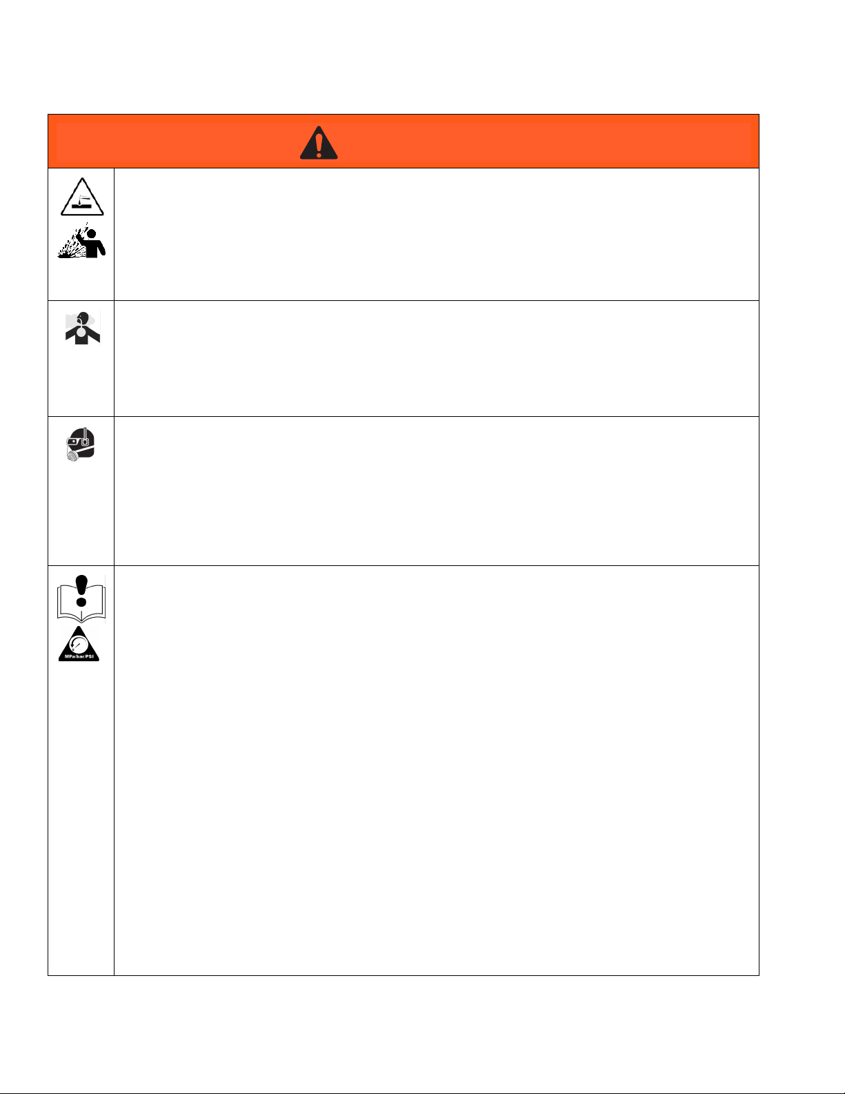
Warnings
Warnings
The following warnings are for the setup, use, grounding, maintenance, and repair of this equipment. The exclamation point symbol alerts you to a general warning and the hazard symbols refer to procedure-specific risks. When
these symbols appear in the body of this manual or on warning labels, refer back to these Warnings. Product-specific
hazard symbols and warnings not covered in this section may appear throughout the body of this manual where
applicable.
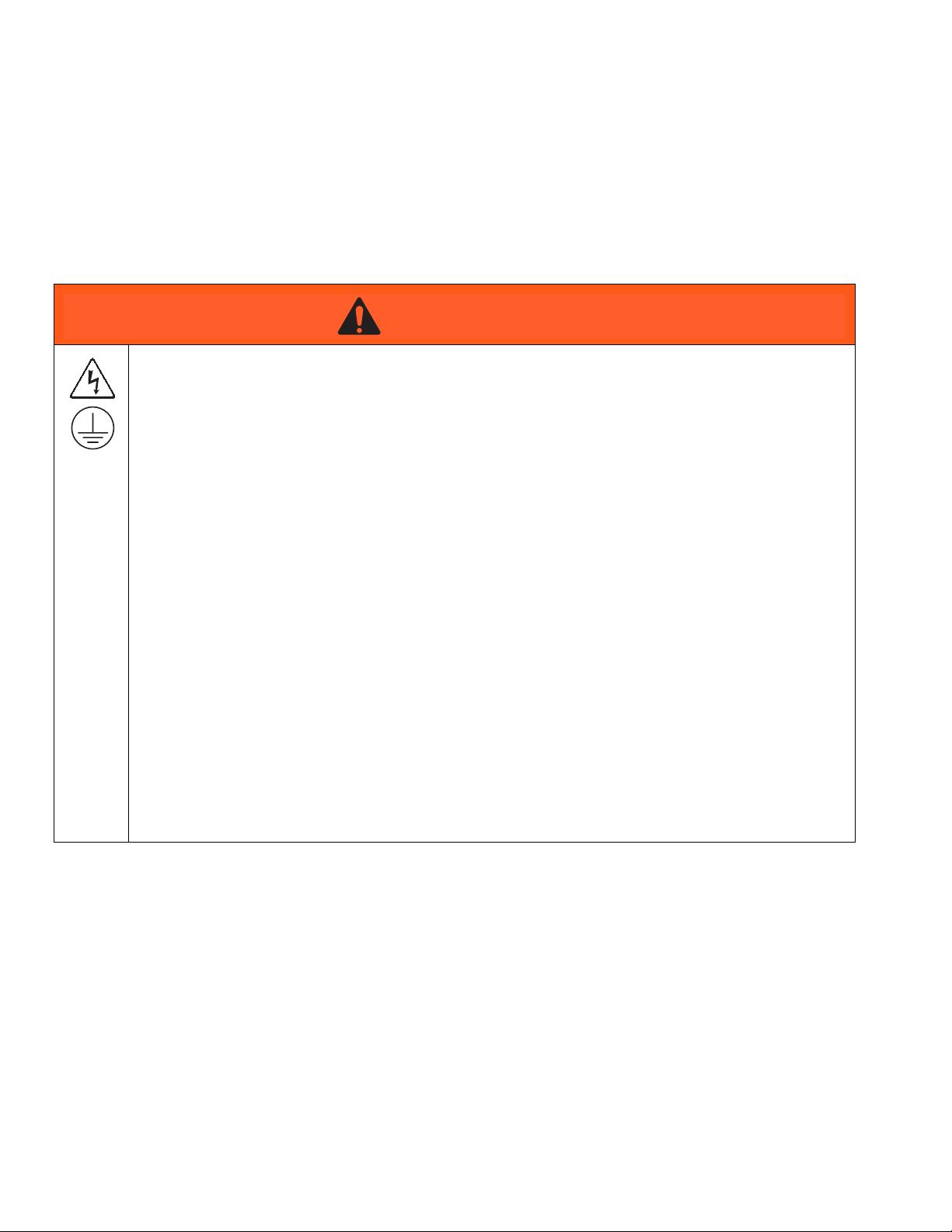
WARNING
WARNINGWARNINGWARNING
ELECTRIC SHOCK HAZARD
Improper grounding, setup, or usage of an isolated waterborne system can result in electric shock. To
help prevent electric shock:
• Ground all equipment, personnel, object being sprayed, and conductive objects in or close to spray
area. See Grounding instructions.
• Connect the electrostatic gun to a voltage isolation system that will discharge the system voltage
when not in use.
• All components of the voltage isolation system that are charged to high voltage must be contained
within an isolation enclosure that prevents personnel from making contact with the high voltage
components before the system voltage is discharged.
• Follow the Fluid Voltage Discharge and Grounding Procedure when instructed to discharge the
voltage; before cleaning, flushing, or servicing the system; before approaching the front of the gun;
and before opening the isolation enclosure for the isolated fluid supply.
• Do not enter a high voltage or hazardous area until all high voltage equipment has been
discharged.
• Do not touch the gun nozzle or electrode, or come within 4 in. (102 mm) of the electrode during gun
operation. Follow the Fluid Voltage Discharge and Grounding Procedure.
• Interlock the gun air supply with the voltage isolation system to shut off the air supply anytime the
isolation system enclosure is opened.
• Only use the red-colored Graco electrically conductive air hose with this gun. Do not use black or
gray-colored Graco air hoses.
• Do not splice fluid hoses together. Install only one continuous Graco Waterborne Fluid Hose
between the isolated fluid supply and the spray gun.
4 333013B
Page 5
Warnings
WARNING
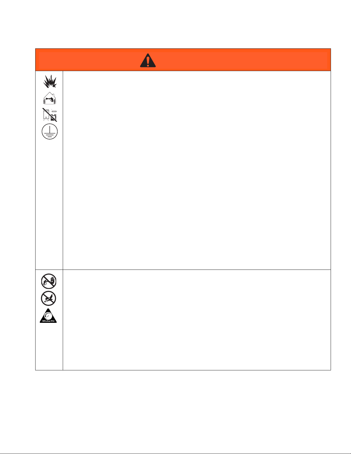
WARNINGWARNINGWARNING
FIRE AND EXPLOSION HAZARD
Combustible dust in work area can ignite or explode. To help prevent fire and explosion:
• Use only fluids that meet the following flammability requirements:
• Material does not sustain burning in accordance with the Standard Test Method for Sustained
Burning of Liquid Mixtures, ASTM D4206.
• Materials which cannot be ignited, in any mixture with air, by an energy source of less than 500
mJ.
• Stop operation immediately if static sparking occurs or you feel a shock. Do not use equipment
until you identify and correct the problem.
• Electrostatic equipment must be used only by trained, qualified personnel who understand the
requirements of this manual.
• Ground all equipment, personnel, object being sprayed, and conductive objects in or close to spray
area. Resistance must not exceed 1 megohm. See Grounding instructions.
• Do not use pail liners unless they are conductive and grounded.
• Check gun resistance, hose resistance, and electrical grounding daily.
• Use and clean equipment only in well ventilated area.
• Interlock the gun air supply to prevent operation unless ventilating fans are on.
• Only use non-flammable solvents when flushing or cleaning equipment.
• Always turn the electrostatics off when flushing, cleaning or servicing equipment.
• Eliminate all ignition sources; such as pilot lights, cigarettes, portable electric lamps, and plastic
drop cloths (potential static arc).
• Do not plug or unplug power cords or turn lights on or off when flammable fumes are present.
• Keep spray area free of debris, including solvent, rags and gasoline.
• Keep a working fire extinguisher in the work area.
SKIN INJECTION HAZARD
High-pressure fluid from gun, hose leaks, or ruptured components will pierce skin. This may look like
just a cut, but it is a serious injury that can result in amputation. Get immediate surgical treatment.
• Do not spray without tip guard and trigger guard installed.
• Engage trigger lock when not spraying.
• Do not point gun at anyone or at any part of the body.
• Do not put your hand over the spray tip.
• Do not stop or deflect leaks with your hand, body, glove, or rag.
• Follow the Pressure Relief Procedure when you stop spraying and before cleaning, checking, or
servicing equipment.
• Tighten all fluid connections before operating the equipment.
• Check hoses and couplings daily. Replace worn or damaged parts immediately.
333013B 5
Page 6
Warnings
WARNING
WARNINGWARNINGWARNING
PLASTIC PARTS CLEANING SOLVENT HAZARD
Many solvents can degrade plastic parts and cause them to fail, which could cause serious injury or
property damage.
• Use only compatible water-based solvents to clean plastic structural or pressure-containing parts.
• See Technical Data in this and all other equipment instruction manuals. Read fluid and solvent
manufacturer’s MSDSs and recommendations.
TOXIC FLUID OR FUMES HAZARD
Toxic fluids or fumes can cause serious injury or death if splashed in the eyes or on skin, inhaled, or
swallowed.
• Read MSDSs to know the specific hazards of the fluids you are using.
• Store hazardous fluid in approved containers, and dispose of it according to applicable guidelines.
PERSONAL PROTECTIVE EQUIPMENT
Wear appropriate protective equipment when in the work area to help prevent serious injury, including
eye injury, hearing loss, inhalation of toxic fumes, and burns. This protective equipment includes but is
not limited to:
• Protective eye wear, and hearing protection.
• Respirators, protective clothing, and gloves as recommended by the fluid and solvent
manufacturer
EQUIPMENT MISUSE HAZARD
Misuse can cause death or serious injury.
• Do not operate the unit when fatigued or under the influence of drugs or alcohol.
• Do not exceed the maximum working pressure or temperature rating of the lowest rated system
component. See Technical Data in all equipment manuals.
• Use fluids and solvents that are compatible with equipment wetted parts. See Technical Data in all
equipment manuals. Read fluid and solvent manufacturer’s warnings. For complete information
about your material, request MSDS from distributor or retailer.
• Do not leave the work area while equipment is energized or under pressure.
• Turn off all equipment and follow the Pressure Relief Procedure when equipment is not in use.
• Check equipment daily. Repair or replace worn or damaged parts immediately with genuine
manufacturer’s replacement parts only.
• Do not alter or modify equipment. Alterations or modifications may void agency approvals and
create safety hazards.
• Make sure all equipment is rated and approved for the environment in which you are using it.
• Use equipment only for its intended purpose. Call your distributor for information.
• Route hoses and cables away from traffic areas, sharp edges, moving parts, and hot surfaces.
• Do not kink or over bend hoses or use hoses to pull equipment.
• Keep children and animals away from work area.
• Comply with all applicable safety regulations.
6 333013B
Page 7
Introduction
Introduction
How the Electrostatic AA Spray Gun Works
This is not an air spray gun. To help prevent serious
injury from pressurized fluid, such as skin injection,
and splashing fluid, read and follow the Skin Injection
Hazard Warnings on page 5.
The air-assisted spray gun combines airless and air
spraying concepts. The spray tip shapes the fluid into a
fan pattern, as does a conventional airless spray tip. Air
from the air cap further atomizes the fluid and completes
the atomization of the fluid tails to produce a uniform
pattern.
The high working fluid pressure of this gun provides the
power needed to atomize higher solids materials.
Operating the Spray Function
Applying a minimum of 60 psi (0.42 MPa, 4.2 bar) air
pressure to the gun manifold’s cylinder air fitting (CYL)
will retract the gun piston, which opens the air valves
and a short time later opens the fluid needle. This provides the proper air lead and lag when triggering the
gun. A spring returns the piston when the cylinder air is
shut off.
Gun Features and Options
• The gun is designed for use with a reciprocator, and
can be mounted directly on a 1/2 in. (13 mm) rod.
With additional brackets, the gun can be mounted
for robotic applications.
• The gun’s quick-disconnect design enables its
removal without disconnecting the air lines to the
gun.
• Gun functions are activated from a separate controller that sends the appropriate signal to the actuating
solenoids.
Smart Gun Features
Smart gun models with the Pro Xp Auto Control Module
have the ability to:
• Display the spraying voltage and current
• Change the gun voltage setting
• Display the gun turbine speed
• Store spray profiles
• Communicate equipment faults to a PLC
• Display and set maintenance totalizers
Operating the Electrostatics
• Use a PLC to select a spray profile
To operate the electrostatics, apply air pressure to the
gun manifold’s turbine air fitting (TA) through a Graco
Grounded Turbine Air Hose. The air enters the manifold
and is directed to the inlet of the power supply turbine.
The air spins the turbine, which then provides electrical
power to the internal high voltage power supply. The
fluid is charged by the spray gun electrode. The charged
fluid is attracted to the nearest grounded object, wrapping around and evenly coating all surfaces.
333013B 7
See the Pro Xp Auto Control Module manual 332989 for
more information.
Page 8

Introduction
Spraying Waterborne Fluids Electrostatically
This electrostatic air spray gun is designed to spray
only waterborne fluids which meet at least one of the
following flammability requirements:
FM, FMc Approved:
• Material does not sustain burning in accordance
with the Standard Test Method for Sustained Burning of Liquid Mixtures, ASTM D4206.
CE-EN 50059 Compliant:
• Materials which cannot be ignited, in any mixture
with air, by an energy source of less than 500 mJ.
When connected to a voltage isolation system, all of the
fluid in the spray gun, fluid hose, and isolated fluid supply is charged to high voltage, which means that the
system has more electrical energy than a solvent-based
system. Therefore, only non-flammable fluids (as
defined above) can be sprayed with the system or used
to clean, flush, or purge the system.
Precautions must be taken when using electrostatic
waterborne equipment to avoid potential shock hazards.
When the electrostatic AA spray gun charges the isolated fluid to high voltage, it is similar to charging a
capacitor or a battery. The system will store some of the
energy while spraying and retain some of that energy
after the spray gun is shut off. Do not touch the gun nozzle or come within 4 in. (102 mm) of the electrode until
the stored energy is discharged. The amount of time it
takes to discharge the energy depends on the system
design. Follow the Operating Checklist on page 22
before approaching the front of the gun.
NOTE: The Graco warranty and approvals are void if
the electrostatic spray gun is connected to a non-Graco
voltage isolation system or if the spray gun is operated
above 60 kV.
8 333013B
Page 9
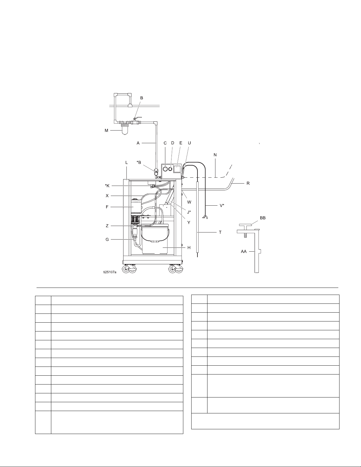
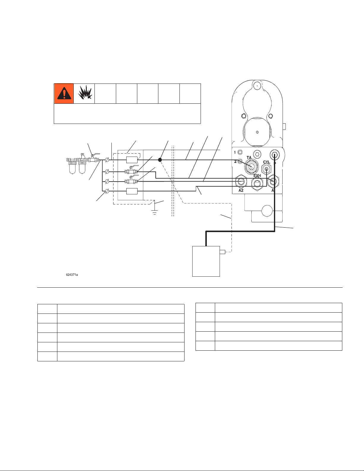
System Overview
Typical Waterborne System Installation
F
IGURE
1 shows a typical electrostatic waterborne AA spray system. It is not an actual system design. For assistance
in designing a system to suit your particular needs, contact your Graco distributor.
Also refer to system pneumatic
connections in F
IGURE
Introduction
3, page 13.
FIG. 1 Typical Installation, Pro Auto Xp Waterborne System
Item Description
A Main Air Supply Line
B* Bleed-Type Air Shutoff Valve
C Pump Air Pressure Gauge
D Pump Air Pressure Regulator
EkV Meter
FPump
G Pump Suction Hose
H Paint Container
J* Bleed Resistor
K* Enclosure Safety Interlock
L Isolated Enclosure
M Air Line Filter
N Pneumatic connection to turbine air interlock.
(Pressurized when isolation system door is
closed)
333013B 9
Item Description
R Graco Waterborne Fluid Hose
T Grounding Rod
U Ground Terminal
V* Main Ground Wire
W Strain Relief Fitting
X Pump Air Supply Line
Y Grounding Cylinder
Z Pump Fluid Outlet Fitting
AA Isolated Enclosure Door (not shown, to illustrate
internal components. Door must be closed and
locked to operate system).
BB Enclosure T-Handle Locking Screw (part of door
assembly)
* These items are required for safe operation. They are
included with the WB3000 system.
Page 10
Introduction
Gun Overview
K
B
J
A
C
D
H
F
G
1
2
CYL
TA
A2
EXH
L
A1
Fig. 2. Gun Overview
Key
AAir Cap
B Spray Tip
C Retaining Ring
D Shroud
FManifold
G Turbine
H Power Supply
J Electrode
L Waterborne Fluid Hose
10 333013B
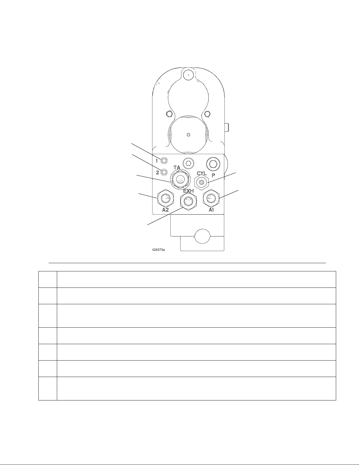
Manifold Markings
A1 Atomization Air Inlet Fitting
A2 Fan Air Inlet Fitting
CYL Cylinder Air Inlet Fitting
1
2
K ES Indicator Light (standard models only)
TA Turbine Air Inlet Fitting
EXH Exhaust Outlet Fitting
Fiber Optic Fitting Transmit
(Operational on Smart models only)
Fiber Optic Fitting Receive
(Operational on Smart models only)
Page 11
Installation
Installation
System Requirements
Basic Guidelines
When spraying waterborne fluids electrostatically:
• The gun must be connected to a voltage isolation
system, which isolates the fluid supply from ground
and allows voltage to be maintained at the tip of the
gun.
• The gun must be connected to a voltage isolation
system that will discharge the system voltage when
the gun is not in use.
• There should be a bleed resistor to drain off the system voltage when the spray gun is not in use.
• All components of the voltage isolation system that
are charged to high voltage must be contained
within an isolation enclosure that prevents personnel from making contact with the high voltage components before the system voltage is discharged.
• The gun turbine air hose must be interlocked with
the voltage isolation system to shut off the turbine
air supply anytime the isolation system enclosure is
opened or entered.
• The voltage isolation system must be interlocked
with the spray area entrance to automatically discharge the voltage and ground the fluid whenever
someone opens the enclosure or enters the spray
area.
• The system should not have any severe arcing
occurring when the isolation mechanism opens and
closes. Severe arcing will shorten the life of the system components.
Graco Waterborne Fluid Hose
Use a Graco Waterborne Fluid Hose between the voltage isolation system fluid outlet and the gun fluid inlet.
See Accessories on page 57 for available hoses. The
hose consists of an inner PTFE tube, a conductive layer
covering the PTFE tube, and an outer cover.
Install the System
Installing and servicing this equipment requires
access to parts which may cause electric shock or
other serious injury if work is not performed properly.
• Do not install or service this equipment unless
you are trained and qualified.
• Comply with all applicable local, state, and
national fire, electrical, and other safety
regulations.
Warning Signs
Mount warning signs in the spray area where they can
easily be seen and read by all operators. An English
Warning Sign is provided with the gun.
Ventilate the Spray Booth
Provide fresh air ventilation to avoid the buildup of
flammable or toxic vapors when spraying, flushing,
or cleaning the gun. Do not operate the gun unless
ventilation fans are operating.
Electrically interlock the gun turbine air supply (B) with
the ventilators to prevent gun operation without ventilating fans operating.
NOTE: High velocity air exhaust will decrease the operating efficiency of the electrostatic system. Check and
follow all National, State, and Local codes regarding air
exhaust velocity requirements.
Air exhaust velocity of 100 ft/min (31 linear meters/minute) should be sufficient.
333013B 11
Page 12
Installation
Install the Air Line Accessories
1. Install a bleed-type air valve (L) on the main air line
(W) to shut off all air to the gun.
2. Install an air line filter/water separator on the main
air supply line to ensure a dry, clean air supply to
the gun. Dirt and moisture can ruin the appearance
of your finished workpiece and can cause the gun to
malfunction.
3. Install a bleed-type air pressure regulator (M) on
each of the air supply lines (B, C, D, E) to control air
pressure to the gun.
4. Install a solenoid valve (K) on the cylinder air line
(E) to actuate the gun. The solenoid valve must
have a quick exhaust port.
5. Install a solenoid valve (K) to actuate the turbine.
Trapped air can cause the gun to spray unexpectedly,
which can result in serious injury, including splashing
fluid in the eyes or on the skin. The solenoid valves (K)
must have a quick exhaust port so trapped air will be
relieved between the valve and gun when the
solenoids are shut off.
Install the Fluid Line Accessories
1. Install a fluid filter and drain valve at the pump outlet. Filtering the fluid will help remove coarse parti-
cles and sediment that could clog the spray tip.
The fluid drain valve is required in your system to
assist in relieving fluid pressure in the displacement
pump, hose, and gun. Triggering the gun to relieve
pressure may not be sufficient. Install a drain valve
close to the pump's fluid outlet. The drain valve
reduces the risk of serious injury, including splashing
in the eyes or on the skin.
12 333013B
Page 13
F
IGURE
3 shows a typical electrostatic air-assisted spray system. It is not an actual system design. For assistance in
designing a system to suit your particular needs, contact your Graco distributor.
The turbine air supply (TA) must be electrically interlocked
with the spray booth ventilation fans to prevent the power
supply from operating without ventilating fans on.
Installation
See Warning
L
W
M
Non-Hazardous Area
FIG. 3 . Typical Installation
Key to F
IGURE
3
above
Pneumatic
A
K
Interlock
L
C
D
B
L
K
N
Hazardous Area
E
Air Line
(Pressurized when
door is closed)
G
Manifold Back View
Voltage
Isolation
System
WB3000
The turbine air must also be interlocked with the
voltage isolation system to shut off the turbine air
when the access to the isolation system is opened.
A Air Hose Ground Wire
B Graco Grounded Turbine Air Hose (TA)
C Atomizing Air Hose, 5/16 in. (8 mm) OD (A1)
D Fan Air Hose, 5/16 in. (8 mm) OD (A2)
E Cylinder Air Hose, 5/32 in. (4 mm) OD (CYL)
K Solenoid Valve, requires quick exhaust port
L Bleed-Type Master Air Valve
M Air Pressure Regulator
N True Earth Ground
W Main Air Line
G Graco Waterborne Fluid Supply Hose
333013B 13
Page 14
Installation
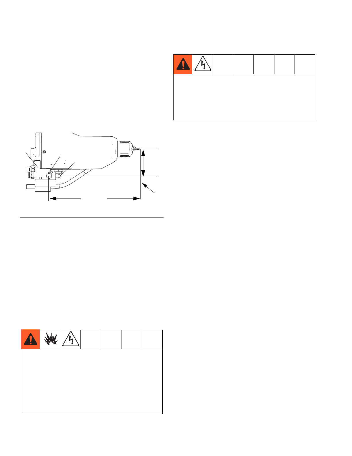
Install the Gun
1. Loosen the manifold’s two set screws (29) and slide
the manifold (20) onto a 1/2 in. (13 mm) mounting
rod.
2. Position the gun and tighten the two set screws.
NOTE: For added positioning reliability, insert a 1/8 in.
(3 mm) locating pin into the slot (NN) in the bracket and
through a hole in the rod. See the detail in F
20
NN
29
8.18 in.
(207.7 mm)
IGURE
4.
2.88 in.
(73.2 mm)
To
nozzle tip
To reduce the risk of electric shock or other serious
injury, the red-colored Graco Grounded Turbine Air
Hose must be used for the turbine air supply hose,
and the hose ground wire must be connected to a
true earth ground. Do not use the black or
gray-colored Graco air hoses.
1. Connect the Graco Grounded Turbine Air Hose (B)
to the gun's turbine air inlet (TA) and connect the
hose ground wire (A) to a true earth ground (N). The
gun turbine air inlet fitting has left-hand threads to
prevent connecting another type of air hose to the
turbine air inlet. See Accessories, on page 57 for
further information about the hose.
2. Check the electrical grounding of the gun as
instructed on page 19.
FIG. 4 Mounting Bracket
Install the Pro Xp Auto Control Module
The Pro Xp Auto Control Module is required for use with
smart models. To install a Pro Xp Auto Control Module,
see the module instruction manual 332989.
Connect the Air Line
F
IGURE
3 shows a schematic of air line connections, and
F
IGURE
5 shows the manifold connections. Connect the
air lines as instructed.
To reduce the risk of a fire, explosion, or electric
shock, the Graco Grounded Turbine Air Hose must
be interlocked with:
• The isolation system to shut off the turbine air
supply anytime the enclosure is opened or
entered.
• The ventilators to prevent operation of the power
supply unless the ventilating fans are on.
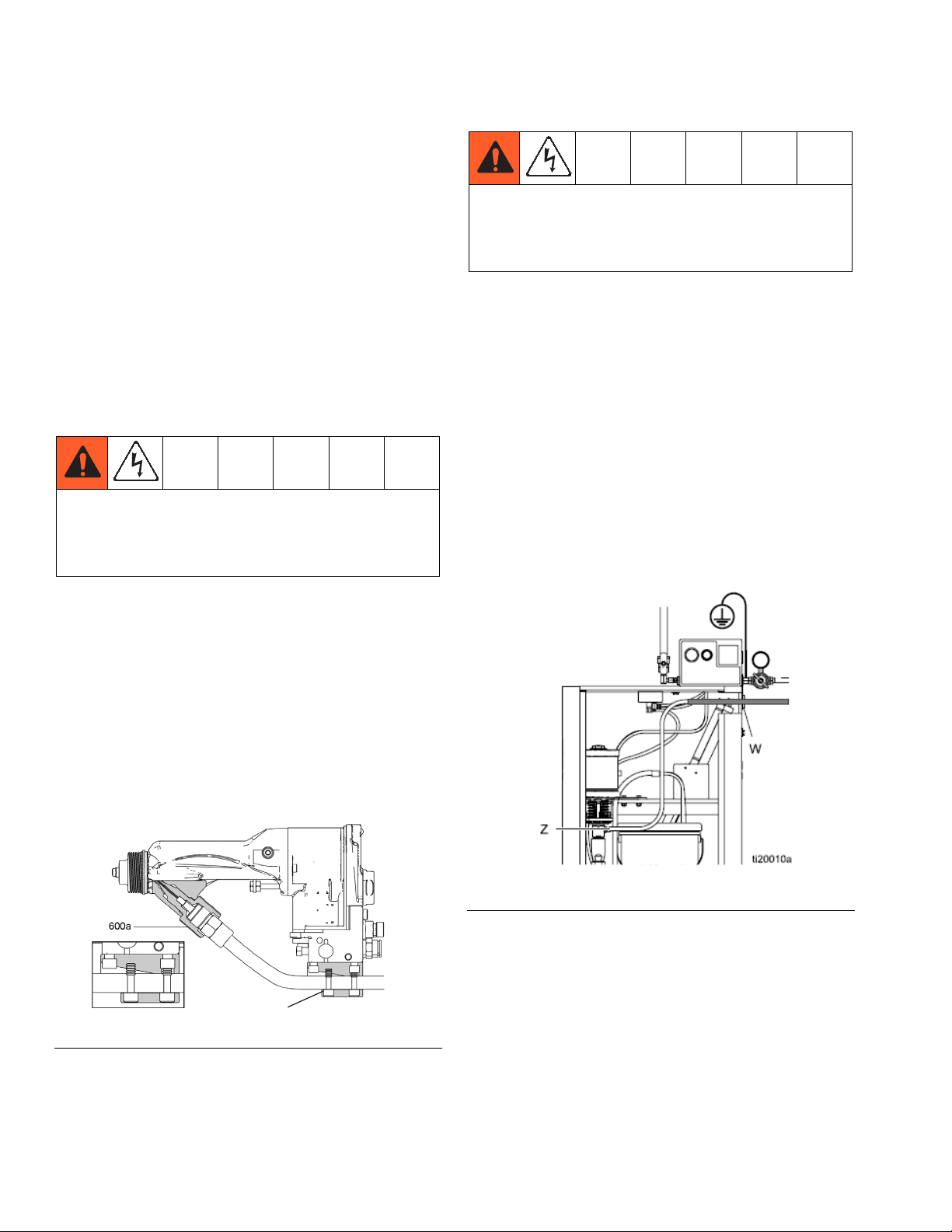
Ground the Cabinet
Connect the main ground wire (V) to a true earth
ground.
14 333013B
Page 15
Manifold Connections
1
2
Installation
TA
A2
EXH
FIG. 5 Manifold Connection
A1 Atomization Air Inlet Fitting
Connect a 5/16” in. (8 mm) OD tube between this fitting and the air supply.
A2 Fan Air Inlet Fitting
Connect a 5/16” in. (8 mm) OD tube between this fitting and the air supply.
CYL Cylinder Air Inlet Fitting
Connect a 5/32 in. (4 mm) OD tube between this fitting and the solenoid. For quicker response, use the
shortest hose length possible.
1 Fiber Optic Fitting Transmit (Operational on Smart models only)
Connect the Graco Fiber Optic cable (see page 17).
2 Fiber Optic Fitting Receive (Operational on Smart models only)
Connect the Graco Fiber Optic cable (see page 17).
EXH Exhaust
Connect a 5/16 in OD exhaust tube to route the turbine exhaust air. (3 ft. max length)
TA Turbine Air Inlet Fitting
Connect the Graco Electrically Conductive Air Hose between this fitting (left-hand thread) and the solenoid.
Connect the air hose ground wire to a true earth ground.
CYL
A1
333013B 15
Page 16
Installation
Connect the Waterborne Fluid Hose
NOTE: The Graco warranty is void if the spray gun is
connected to a non-Graco voltage isolation system or if
the gun is operated above 60 kV.
Always use a Graco Waterborne Fluid Hose between
the voltage isolation system fluid outlet and the gun fluid
inlet.
Before connecting the Waterborne Fluid Hose to the
gun, blow it out with air and flush with water to remove
contaminants. Flush the gun before using it. See Flush-
ing, page 26.
To reduce the risk of electric shock, install only one
continuous Graco Waterborne Fluid Hose between
the isolated fluid supply and the spray gun. Do not
splice hoses together.
1. Remove the air cap (25), spray tip (3), and shroud
(26).
To reduce the risk of electric shock, the areas of the
Graco Waterborne Fluid Hose that are accessible to
personnel during normal operation must be covered
by the black outer hose jacket.
5. Connect the other end of the fluid hose to the isolated fluid supply as follows:
a.
Graco WB3000 Enclosure:
of the hose through the hole in the side of the
isolated enclosure. Connect the swivel (Z) to the
fluid outlet of the pump. Secure the hose to the
side of the enclosure with the bracket (W).
b.
Non-Graco Isolated Enclosure:
as instructed in the isolation system manual.
6. Reinstall the shroud (26), spray tip (3), and air cap
(25).
7. Check the gun’s electrical grounding (see page 19).
Slide the other end
Connect hose
2. Ensure the barrel fluid inlet is clean and dry. Apply
dielectric grease to the threads of the barrel connector (600a) and screw it in to the fluid inlet.
3. Apply dielectric grease to the threads of the hose
(600) and screw it in to the barrel connector (600a).
4. Secure hose in strain relief bracket by tightening the
four plastic screws.
Strain Relief Bracket
FIG. 6 Connect the Waterborne Fluid Hose
FIG. 7 . Unshielded Hose 24W599 Connection at
WB3000 Enclosure
16 333013B
Page 17
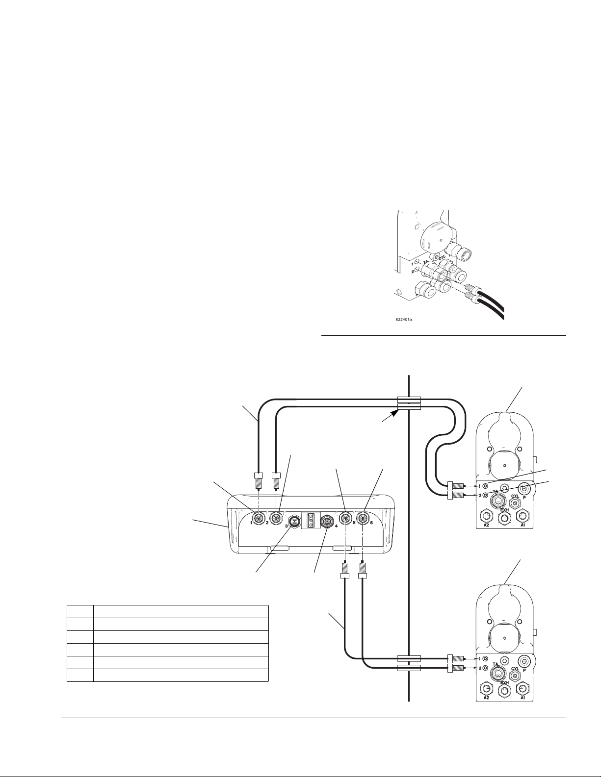
Fiber Optic Cable Connection
(Operational on Smart models only)
Installation
NOTE: Only use the supplied fiber optic cable.
The fiber optic cable allows the gun to communicate
with the Pro Xp Auto control module.
For a 1 Gun System
1. Connect Port 1 of the gun 1 manifold to Port 1 of the
Control Module.
2. Connect Port 2 of the gun 1 manifold to Port 2 of the
Control Module.
Non-Hazardous Area
V
For a 2 Gun System
1. Connect Port 1 of the gun 2 manifold to Port 5 of the
Control Module.
2. Connect Port 2 of the gun 2 manifold to Port 6 of the
Control Module.
FIG. 8 . Making Fiber Optic Connections
Hazardous Area
H
Port 1
R
Key for F
H PRO Xp Auto Waterborne AA Spray Gun
P 24 Volt Power Supply Connection
Q Remote I/O Connection
R Remote Control Module
U Bulkhead
V Fiber Optic Cable
IGURE
9
U
Port 2
Port 5
Port 6
1
2
Gun 1
H
P
Q
V
Gun 2
FIG. 9 . Fiber Optic Schematic
333013B 17
Page 18
Installation
Agitator Kit Accessory
To add an agitator to the Graco isolation system, order
Part No. 245895. See Agitator Kit 245895, page 56, for
the kit parts list.
1. Discharge the system voltage (see Fluid Voltage
Discharge and Grounding Procedure, page 22).
2. Relieve the pressure (see Pressure Relief Proce-
dure, page 22).
3. Open the isolated enclosure door.
4. Remove the back of the control box (258).
5. Remove tube (A2) from elbow (282) at the air manifold; see Tubing and Wiring, page 54. Install the Y
fitting (402) into the elbow. Install tubes (A2) and
(407) into the Y fitting. Route the agitator tube (407)
into the cabinet.
6. Replace the back of the control box (258).
7. Assemble the other parts of the kit as shown.
Secure the agitator with the setscrew (408).
8. Return the system to service.
Grounding
When operating the electrostatic gun, any
ungrounded objects in the spray area (people,
containers, tools, etc.) can become electrically
charged. Improper grounding can result in static
sparking, which can cause a fire, explosion, or
electric shock. Ground all equipment, personnel,
object being sprayed, and conductive objects in or
close to the spray area. Resistance must not exceed
1 megohm. Follow the grounding instructions below.
The following are minimum grounding requirements for
a basic electrostatic waterborne system. Your system
may include other equipment or objects which must be
grounded. Check your local electrical code for detailed
grounding instructions. Your system must be connected
to a true earth ground.
•
Electrostatic Air Spray Gun:
necting the red-colored Graco Grounded Air Hose
to the turbine air inlet and connecting the air hose
ground wire to a true earth ground. See Check
Electrical Grounding, page 19
ground the gun by con-
401
406
403
408
404
406
FIG. 10 245895 Agitator Kit
407
402
1
2
•
Voltage Isolation System:
voltage isolation system to a true earth ground.
•
Air compressors and hydraulic power supplies:
ground the equipment according to the manufacturer's recommendations.
•
All persons entering the spray area:
have conductive soles, such as leather, or personal
grounding straps must be worn. Do not wear shoes
with non-conductive soles such as rubber or plastic.
•
Object being sprayed:
clean and grounded at all times. Resistance must
not exceed 1 megohm.
•
The floor of the spray area:
ductive and grounded. Do not cover the floor with
cardboard or any non-conductive material which
would interrupt grounding continuity.
•
Flammable liquids in the spray area:
approved, grounded containers. Do not use plastic
containers. Do not store more than the quantity
needed for one shift.
electrically connect the
shoes must
keep the workpiece hangers
must be electrically con-
must be kept in
18 333013B
Page 19
Installation
•
All electrically conductive objects or devices in the
spray area:
including fluid containers and wash
cans, must be properly grounded.
•
Fluid and waste containers:
ground all fluid and
waste containers in the spray area. Do not use pail
liners unless they are conductive and grounded.
When flushing the spray gun, the container used to
catch the excess fluid must be electrically conductive and grounded.
•
All solvent pails:
use only approved, grounded metal
containers, which are conductive. Do not use plastic
containers. Use only non-flammable solvents. Do
not store more than the quantity needed for one
shift.
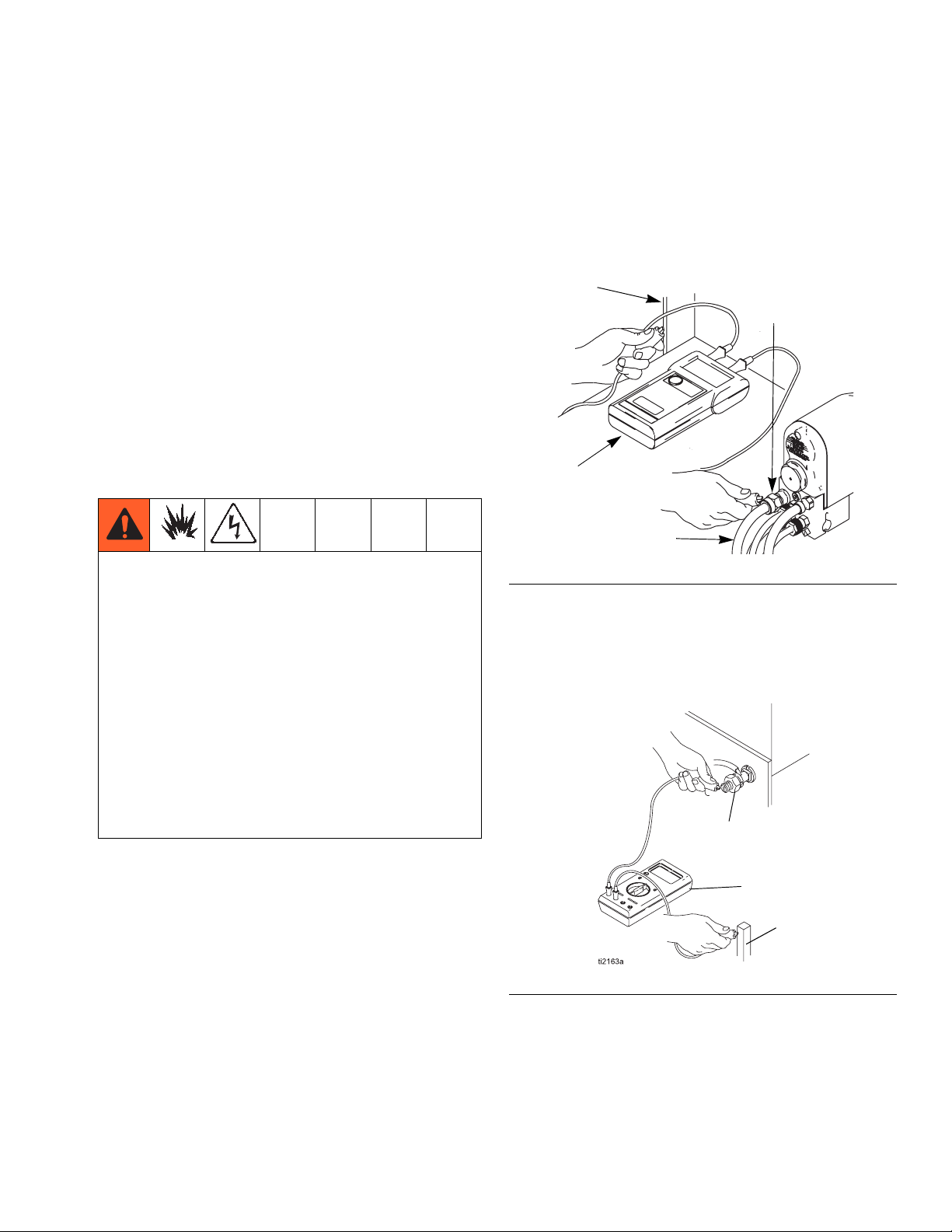
Check Electrical Grounding
Megohmmeter Part No. 241079 (AA-see F
is not approved for use in a hazardous area. To
reduce the risk of sparking, do not use the
megohmmeter to check electrical grounding unless:
• The gun has been removed from the hazardous
area;
• Or all spraying devices in the hazardous area are
turned off, ventilation fans in the hazardous area
are operating, and there are no flammable vapors
in the area (such as open solvent containers or
fumes from spraying).
Failure to follow this warning could cause fire,
explosion, and electric shock and result in serious
injury and property damage.
IGURE
11)
4. Measure the resistance between the turbine air inlet
fitting (TA) and a true earth ground (N). If the resistance is greater than 100 ohms, check the tightness
of the ground connections and be sure the turbine
air hose ground wire is connected to a true earth
ground. If the resistance is still too high, replace the
turbine air hose
N
TA
AA
WLD
B
Fig. 11. Check Gun Grounding
5. If using the WB3000 use an ohmmeter (AA) measure the resistance between the cabinet ground lug
(214) and a true earth ground (CC). The resistance
must be less than 100 ohms.
214
Graco Part No. 241079 Megohmmeter is available as an
accessory to check that the gun is properly grounded.
1. Have a qualified electrician check the electrical
AA
CC
grounding continuity of the spray gun and turbine air
hose.
2. Make sure the red-colored turbine air hose (B) is
FIG. 12 . Check Cabinet Grounding
connected and the hose ground wire is connected to
a true earth ground.
3. Turn off the air and fluid supply to the gun. Follow
the Pressure Relief Procedure, page 22. The fluid
hose must not have any fluid in it.
333013B 19
Page 20

Installation
Install the Fabric Cover
See F
IGURE
13.
1. Install a fabric cover (XX) over the front of the gun
and slide it back to cover the exposed tubing and
hoses at the back of the manifold.
2. Route the exhaust tube (YY) outside the cover. This
enables you to monitor the exhaust tube for the
presence of any paint or solvent. See Check for
Fluid Leakage on page 28. Strap down the exhaust
tube to prevent it from moving around.
YY
XX
Check Fluid Viscosity
To check fluid viscosity you will need:
• a viscosity cup
• a stopwatch
1. Completely submerge the viscosity cup in the fluid.
Lift the cup out quickly, starting the stopwatch as
soon as the cup is completely removed.
2. Watch the stream of fluid coming from the bottom of
the cup. As soon as there is a break in the stream,
shut off the stopwatch.
3. Record the fluid type, elapsed time, and size of the
viscosity cup.
4. If the viscosity is too high or too low, contact the
material supplier. Adjust as necessary.
Flush Before Using Equipment
The equipment was tested in fluid at the factory. To
avoid contaminating your fluid, flush the equipment with
a compatible solvent before using the equipment. See
Flushing, page 26.
YY
WLD
FIG. 13 . Fabric Cover
20 333013B
Page 21

Operation
Operation
Operating Checklist
Check the following list daily, before starting to operate the system, to help ensure you of safe, efficient operation.
All operators are properly trained to safely operate an automatic electrostatic waterborne air spray system as
instructed in this manual.
All operators are trained in the Fluid Voltage Discharge and Grounding Procedure on page 22.
All operators are trained in the Pressure Relief Procedure on page 22.
The electrostatics are turned off and system voltage is discharged according to the Fluid Voltage Discharge
and Grounding Procedure, page 22, before any person enters the isolation enclosure, before cleaning, and
before performing any maintenance or repair.
The warning sign provided with the gun is mounted in the spray area where it can be easily seen and read by
all operators.
The system is thoroughly grounded and the operator and all persons entering the spray area are properly
grounded. See Grounding on page 18.
The Graco Waterborne Fluid Hose is in good condition with no cuts or abrasions. Replace hose if damaged.
The condition of the gun’s electrical components has been checked as instructed in Electrical Tests on page
29.
All fluid hose connections are tight.
Ventilation fans are operating properly.
Workpiece hangers are clean and grounded.
All debris, including flammable fluids and rags, is removed from the spray area.
All conductive objects in the spray area are electrically grounded and the floor of the spray area is electrically
conductive and grounded.
All flammable fluids in the spray booth are in approved, grounded containers.
The manifold exhaust tubes have been checked for the presence of any fluid as instructed in Check for Fluid
Leakage on page 28.
Fluids used must meet the following flammability requirements:
FM, FMc Approved:
Material does not sustain burning in accordance with the Standard Test Method for Sustained Burning of Liquid
Mixtures, ASTM D4206.
CE-EN 50059 Compliant:
Materials which cannot be ignited, in any mixture with air, by an energy source of less than 500mJ.
333013B 21
Page 22

Operation
Fluid Voltage Discharge and Grounding Procedure
The fluid supply is charged with high voltage until the
voltage is discharged. Contact with the charged
components of the voltage isolation system or spray
gun electrode will cause an electric shock. To avoid
an electric shock, follow the Fluid Voltage
Discharge and Grounding Procedure:
• whenever you are instructed to discharge the
voltage
• before cleaning, flushing, or servicing the system equipment
• before approaching the front of the gun
• or before opening the isolation enclosure for
the isolated fluid supply.
NOTE: An accessory grounding rod, part No. 210084, is
available to discharge any voltage remaining on a system component. Contact your Graco distributor to order.
Pressure Relief Procedure
Follow the Pressure Relief Procedure whenever
you see this symbol.
This equipment stays pressurized until pressure is
manually relieved. To help prevent serious injury
from pressurized fluid, such as skin injection and
splashing fluid follow the Pressure Relief Procedure
when you stop spraying and before cleaning,
checking, or servicing the equipment.
1. Follow the Fluid Voltage Discharge and Ground-
ing Procedure, page 22.
2. Relieve fluid pressure in the fluid supply and voltage
isolation system as instructed in their instruction
manuals.
3. Turn off all the air to the spray gun except the cylinder air, which triggers the gun.
1. Turn off the turbine air to all spray guns connected
to the isolated fluid supply and wait 30 seconds.
2. Discharge the voltage at the voltage isolation system by following the procedure specified in the voltage isolation system instruction manual.
For WB3000: fully unscrew the door T-handle locking screw. This will shut off the air to the gun and
trigger the grounding cylinder to discharge any
remaining electrical charge.
3. Touch the pump, supply pail, and electrode of the
gun with a grounded rod to make sure the voltage
has been discharged. If you see an arc, verify that
the electrostatics are turned off or see Electrical
Troubleshooting, page 37 or the voltage isolation
system manual for other possible problems.
Resolve the problem before proceeding.
NOTE: The air shut-off device must bleed the air out of
the system.
4. Trigger the gun into a grounded metal waste container to relieve the fluid pressure.
5. Turn off all remaining air supplies to the gun.
6. Turn off the main air supply by closing the
bleed-type master air valve on the main air supply
line. Leave the valve closed until you are ready to
spray again.
7. If you suspect the fluid hose or tip is plugged, or that
pressure is not fully relieved after following the steps
above, slowly loosen the fluid hose fitting at the
pump to relieve pressure gradually, then loosen
completely.
Select a Spray Tip
The fluid output and pattern width depend on the size of
the spray tip, the fluid viscosity, and the fluid pressure.
Use the Spray Tip Selection Chart, page 59, as a
guide for selecting the appropriate spray tip for your
application.
22 333013B
Page 23

Operation
Install the Spray Tip
To reduce the risk of an injury, follow the Pressure
Relief Procedure before removing or installing the
spray tip or air cap/tip guard.
Install the spray tip as explained in Air Cap/Tip Guard,
Spray Tip, and Fluid Seat Housing Replacement,
page 39.
1. Follow the Pressure Relief Procedure, page 22.
2. Align the spray tip tab with the groove in the air cap.
Install the tip.
WLD
FIG. 14 Spray Tip Alignment
4. Remove the pail cover from the pail, holding a rag
over the suction tube strainer to prevent any fluid
from dripping into the isolated enclosure. Place the
cover and suction tube outside the enclosure.
5. Remove the supply pail from the enclosure.
NOTICE
Be sure to wipe up all fluid spills in the isolated enclosure. Fluid can create a conductive path and cause the
system to short out.
6. Clean up any fluid spills in the enclosure, using a
soft cloth and a non-flammable, compatible solvent.
7. Fill the supply pail with fluid and return it to the
enclosure. Clean up any spills.
8. Reinstall the pail cover, holding a rag over the suction tube strainer to prevent fluid spills while you
place the pump suction tube in the pail.
9. Close the isolated enclosure door and fasten
securely with the T-handle locking screw.
3. Install the air cap and retaining ring. Orientate the
air cap and tighten the retaining ring securely. Be
careful not to damage the electrode.
WLD
FIG. 15 Install Air Cap Assembly
To reduce the risk of fire, explosion, or electric
shock, never operate the gun with a damaged
electrode.
Fill the Fluid Supply
Set the Atomization Fluid Pressure
Atomization fluid pressure will vary based on the viscosity of the fluid, flow rate desired, and other system characteristics.
1. Turn off the turbine air (TA), atomization air (A1),
and fan air (A2).
2. Start the pump. Set the fluid regulator to 400 psi (2.8
MPa, 28 bar).
3. With the turbine air (TA), atomization air (A1), and
fan air (A2) turned off, spray a test pattern, holding
the gun 12 in. (305 mm) from the surface. Examine
the particle size. Do not be concerned about the
presence of tails; they will be removed in step 6.
4. Increase the fluid pressure in small increments.
Spray another pattern and compare the particle
size. Smaller particle size indicates improved atomization.
1. Follow the Fluid Voltage Discharge and Ground-
ing Procedure, page 22.
2. Follow the Pressure Relief Procedure, page 22.
3. Open the isolated enclosure door.
333013B 23
To reduce the risk of injury, never exceed the
maximum working pressure on the lowest rated
system component. Maximum working pressure of
this equipment is 3000 psi (21 MPa, 210 bar).
Page 24

Operation
5. Continue to increase the fluid pressure and spray
test patterns. Do not exceed 3000 psi (21 MPa, 210
bar) fluid pressure. When the particle size remains
constant, the fluid is being atomized at the lowest
possible fluid pressure.
For improved atomization at lower fluid flow rates,
change to a smaller tip orifice size.
6. Turn on the atomization air (A1) and adjust the air
pressure until the tails disappear.
See Spray Pattern Troubleshooting on page 34 to
correct spray pattern problems.
7. The pattern width can also be reduced by applying
fan air pressure (A2).
Correct
No Air
Too Little Air
Amount of Air
FIG. 16 Eliminating Tails
Adjust the Electrostatics
1. Shut off the fluid supply.
4. Check the turbine speed of the gun by checking the
indicator light on the standard gun body or for the
smart gun check the actual turbine speed on the Pro
Xp Auto Control Module. See Table 2 . Adjust the
air pressure as necessary to keep the indicator light
green or the values within 100-750 Hz.
NOTE: Smart models display values not color indicator
lights.
Table 2. Indicator Colors/Values
Indicator
Description
Color
Green
400-750 Hz
When spraying, the indicator should
remain green, indicating sufficient air
pressure to the turbine.
Amber
<400
If the indicator changes to amber after 1
second, the air pressure is too low.
Increase air pressure until the indicator is
green.
Red
>750
If the indicator changes to red after 1 second, the air pressure is too high.
Decrease air pressure until the indicator is
green. Excessive turbine speed can
shorten the bearing life and will not
increase the voltage output.
5. Check the voltage output by reading the kV meter
on the isolated enclosure. 45-55 kV is normal.
See Electrical Troubleshooting, page 37 to correct
voltage problems.
2. Prepare the isolation system for high voltage operation.
3. Turn on the turbine air (TA) and adjust the air pressure per the settings in Table 1 . Set the proper
pressure at the turbine air hose inlet
flowing
.
when air is
Table 1. Approximate Dynamic Turbine Air
Pressures
Turbine Air
Hose Length
ft (m)
Air pressure at turbine air hose inlet
for full voltage
psi (bar, MPa)
15 (4.6) 54 (3.8, 0.38)
25 (7.6) 55 (3.85, 0.38)
36 (11) 56 (3.9, 0.39)
50 (15.3) 57 (4.0, 0.40)
75 (22.9) 59 (4.1, 0.41)
100 (30.5) 61 (4.3, 0.43)
24 333013B
Page 25

Operation
Spraying
To reduce the risk of electric shock, do not touch the
gun electrode or come within 4 in. (10 cm) of the
nozzle during gun operation.
1. Apply a minimum of 60 psi (4.2 bar, 0.42 MPa) air
pressure to the cylinder air fitting (CYL) to activate
the on/off sequence of atomization air (A1), fan air
(A2), and fluid (P1). See F
2. Turn the gun functions on and off by using the air
solenoid valves on the cylinder (CYL) and turbine
(TA) air supply lines.
3. For smart gun models, to change to a lower voltage
setting, see the Remote Control Module manual
332989.
If any fluid leakage from the gun is detected, stop
spraying immediately. Fluid leakage into the gun
shroud could cause fire or explosion and result in
serious injury and property damage. See Check for
Fluid Leakage, page 28.
IGURE
2.
Triggering the Fluid Alone
1. Shut off and relieve the air pressure to the atomization (A1) and fan (A2) air lines, using the bleed-type
air shutoff valves.
2. Apply 60 psi (4.2 bar, 0.42 MPa) air pressure to the
cylinder air fitting (CYL) to trigger the fluid.
Shutdown
1. Follow the Fluid Voltage Discharge and Grounding Procedure, page 22.
2. Follow the Pressure Relief Procedure, page 22.
3. Flush and clean the equipment. See Maintenance
on page 26.
333013B 25
Page 26

Maintenance
Maintenance
To reduce the risk of an injury, follow the Pressure
Relief Procedure and the Fluid Voltage Discharge
and Grounding Procedure before doing any
maintenance on the gun or system.
Flushing
• Flush before changing fluids, before fluid can dry in
the equipment, at the end of the day, before storing,
and before repairing equipment.
• Flush at the lowest pressure possible. Check connectors for leaks and tighten as necessary.
Daily Care and Cleaning Checklist
Check the following list daily upon completion of equipment usage.
Flush the gun. See Flushing, page 26.
Clean the fluid and air line filters.
Clean the outside of the gun. See Clean Out-
side of Gun, page 27.
Clean the air cap, spray tip, and tip guard
daily, minimum. Some applications require
more frequent cleaning. Replace the parts if
they are damaged. See Clean the Spray
Gun, page 27.
Check the electrode and replace if broken or
damaged. See Electrode Replacement on
page 40.
Check for fluid leakage from the gun and fluid
hoses. See Check for Fluid Leakage on
page 28. Tighten fittings or replace equipment
as needed.
Check Grounding,
page 18
.
• Flush with a fluid that is compatible with the fluid
being dispensed and the equipment wetted parts.
To reduce the risk of fire, explosion, or electric
shock, turn off the turbine air (TA) before flushing the
gun.
Follow the Fluid Voltage Discharge and Grounding
Procedure, page 22, before flushing.
Only flush, purge, or clean the gun with fluids that
meet the following flammability requirements:
FM, FMc Approved:
Material does not sustain burning in accordance with
the Standard Test Method for Sustained Burning of
Liquid Mixtures, ASTM D4206.
CE-EN 50059 Compliant:
Materials which cannot be ignited, in any mixture with
air, by an energy source of less than 500mJ.
NOTICE
Do not use methylene chloride as a flushing or
cleaning solvent with this gun as it will damage nylon
components.
1. Turn off the turbine air and wait 30 seconds for the
voltage to bleed off.
2. Discharge the system voltage. See Fluid Voltage
Discharge and Grounding Procedure, page 22.
3. Follow the Pressure Relief Procedure, page 22.
4. Remove and clean the air cap and spray tip.
5. Change the fluid source to non-flammable solvent.
6. Trigger the gun to flush the fluid passages clean.
26 333013B
Page 27

Clean Outside of Gun
NOTICE
• Clean all parts with a non-conductive, compatible
solvent. Conductive solvents can cause the gun to
malfunction.
• Fluid in the air passages could cause the gun to
malfunction and could draw current and reduce the
electrostatic effect. Fluid in the power supply cavity
can reduce the turbine life. Whenever possible,
point the gun down when cleaning it. Do not use
any cleaning method which could allow fluid into
the gun air passages.
1. Follow the Fluid Voltage Discharge and Ground-
ing Procedure, page 22
2. Flush the gun. See Flushing, page 26
Maintenance
To reduce the risk of an injury, follow the Pressure
Relief Procedure when you stop spraying and
whenever you are instructed to relieve the pressure.
1. Discharge the system voltage.
2. Follow the Pressure Relief Procedure, page 22.
3. Remove the retaining ring (24), air cap/tip guard
(25), spray tip (3), and gun shroud (26). See page
39.
4. Dip the end of a soft bristle brush into compatible
solvent. clean the front of the gun with the brush.
Avoid getting any solvent into the air passages.
Whenever possible, point the gun down when
cleaning it. See F
IGURE
17
3. Follow the Pressure Relief Procedure, page 22.
4. Clean the outside of the gun with a compatible solvent. Use a soft cloth. Wring out excess fluid from
cloth. Point the gun down to prevent solvent from
entering the gun passages. Do not immerse the
gun.
WLD
WLD
WLD
Clean the Spray Gun
Equipment Needed
• soft bristle brush
• compatible solvent
Procedure
If it appears that there is paint inside the air passages, remove the gun from the line for servicing.
02007
FIG. 17 Clean Front of Gun
5. Dampen a soft cloth with solvent and wring out the
excess. Wipe the exterior of the gun and shroud
clean. See F
IGURE
18.
Contact with the charged components of the spray
gun will cause an electric shock. Do not touch the
FIG. 18 Clean Gun Body
gun nozzle or electrode or come within 4 in. (102
mm) of the front of the gun during operation or until
performing the Fluid Voltage Discharge and
Grounding Procedure, page 22.
6. Clean the retaining ring (24), air cap/tip guard
assembly (25), and spray tip (3) with a soft brush
daily, minimum. Replace any damaged parts. Be
careful not to damage the electrode (25a).
333013B 27
Page 28

Maintenance
NOTICE
Do not use metal tools to clean the
air cap/tip guard or spray tip holes
as this could scratch them, and
make sure the electrode is not damaged. Scratches in the air cap or
spray tip or a damaged electrode
can distort the spray pattern.
7. Wipe off the parts with a dry cloth. Be careful not to
damage the electrode.
To reduce the risk of fire, explosion, or electric
shock, never operate the gun with a damaged
electrode.
8. Check the electrode (25a). Replace if damaged.
9. Check the condition of the spray tip gasket and
install the spray tip in the aircap, page 23.
10. Install the spray tip and air cap/tip guard, shroud,
and retaining ring, page 23. Be sure the electrode
(25a) is in place.
Check for Fluid Leakage
If any fluid leakage from the gun is detected, stop
spraying immediately. Fluid leakage into the gun
shroud could cause fire or explosion and result in
serious injury and property damage.
To reduce the risk of an injury, follow the Pressure
Relief Procedure when you stop spraying and
whenever you are instructed to relieve the pressure.
During operation, periodically check all openings of the
gun shroud (ZZ) for the presence of fluid. See F
19. Fluid in these areas indicates leakage into the
shroud, which could be caused by leaks at the fluid tube
connections or fluid packing leakage.
If fluid is seen in these areas, stop spraying immediately. Discharge the system voltage, relieve the pressure, then remove the gun for repair.
IGURE
11. Test Gun Resistance, page 29.
ZZ
FIG. 19 Check for Fluid Leakage
ZZ
Clean the cabinet
• Inspect the cabinet and clean up any spilled paint.
Conductive paint residue allowed to contact
grounded parts may short out the electrostatics.
• Keep the inside of the cabinet clean, for proper
operation.
• Inspect the door T-handle locking screw regularly,
to ensure the threads are well greased. Apply silicone-free grease to the threads when necessary.
• Visually inspect the ground strip (240) for damage.
Replace if needed. Measure the resistance weekly.
See Test Ground Strip Resistance, page 30.
28 333013B
Page 29

Electrical Tests
Electrical Tests
Use the following procedures to test the condition of the
power supply and gun body, and electrical continuity
between components. See Power Supply Removal
and Replacement, page 43.
Use megohmmeter Part No. 241079 (AA) and an
applied voltage of 500 V. Connect the leads as shown.
Megohmmeter Part No. 241079 (AA-see F
is not approved for use in a hazardous area. To
reduce the risk of sparking, do not use the
megohmmeter to check electrical grounding unless:
• The gun has been removed from the hazardous
area;
• Or all spraying devices in the hazardous area are
turned off, ventilation fans in the hazardous area
are operating, and there are no flammable vapors
in the area (such as open solvent containers or
fumes from spraying).
Failure to follow this warning could cause fire,
explosion, and electric shock and result in serious
injury and property damage.
IGURE
20)
Test Power Supply Resistance
1. Remove the power supply (7), page 43.
2. Remove the turbine (8) from the power supply, page
44.
3. Measure resistance from the power supply's ground
strips (EE) to the spring (7a). See F
4. The resistance should be 90-115 megohms. If outside this range, replace the power supply. If in
range, proceed to the next test.
5. If you still have problems, refer to Electrical Trou-
bleshooting, page 37 for other possible causes of
poor performance, or contact your Graco distributor.
6. Be sure the spring (7a) is in place before reinstalling
the power supply.
IGURE
21.
Test Gun Resistance
1. Flush and dry the fluid passage.
2. Measure the resistance between the electrode (25a)
and the turbine air fitting. The resistance should be
104–150 megohms. If outside this range, go to Test
Power Supply Resistance, page 29. If in range,
see Voltage Loss Troubleshooting, page 31 for
other possible causes of poor performance, or contact your Graco distributor.
AA
25a
FIG. 20 . Test Gun Resistance
TA
TA
7a
FIG. 21 . Test Power Supply Resistance
EE
Test Barrel Resistance
1. Insert a conductive rod (B) into the gun barrel
(removed for the power supply test) and against the
metal contact (C) in the front of the barrel.
2. Measure the resistance between the conductive rod
(B) and the conductive ring (33). See F
The resistance should be 10-30 megohms. If the
resistance is incorrect, make sure the metal contact
(C) in the barrel and the conductive ring (33) are
clean and undamaged.
IGURE
22.
333013B 29
Page 30

Electrical Tests
3. If the resistance is still outside the range, remove
the conductive ring (33) and measure the resistance
between the conductive rod (B) and the wire lead at
the bottom of the conductive ring groove.
4. If the resistance is in range, replace the conductive
ring (33) with a new one. Insert the ends of the conductive ring into the slots (S) at the front of the barrel, then press the ring firmly into the groove.
S
G
The conductive ring (33) is a conductive (metal) contact ring, not a sealing o-ring. To reduce the risk of fire,
explosion, or electric shock:
• Do not remove the conductive ring except to
replace it.
• Never operate the gun without the conductive ring
in place.
• Do not replace the conductive ring with anything
but a genuine Graco part.
5. If the resistance is still outside the range, replace
the gun barrel.
Test Ground Strip Resistance
Using an ohmmeter, measure the resistance between
the latch housing (206) and the ground lug (214). The
ground strip is grounded through the cart back to the
ground lug. Resistance must be less than 100 ohms. If
greater than 100 ohms, replace the ground strip (240).
206
214
FIG. 23 . Test Electrode Resistance
Test Cylinder Resistance
Remove the enclosure door. Using an ohmmeter, measure the resistance from the pump (209) to the ground
lug (214). Resistance must be less than 100 ohms. If
greater than 100 ohms, replace the grounding cylinder
(227).
33
FIG. 22 Test Gun Barrel Resistance
30 333013B
C
B
FIG. 24 Test Cylinder Resistance
Page 31

Troubleshooting
Installing and servicing this equipment requires
access to parts which may cause an electric shock or
other serious injury if the work is not performed
properly. Do not install or repair this equipment
unless you are trained and qualified.
Follow the Fluid Voltage Discharge and
Grounding Procedure before checking or servicing
the system and whenever you are instructed to
discharge the voltage.
Troubleshooting
Before troubleshooting or servicing the voltage isolation
system itself, you need to determine which component
in the system is most likely causing a problem. Possible
causes include the following:
Spray Gun
• Fluid leakage
• Dielectric breakdown at the fluid hose connection or
fluid packings
• Not enough air pressure for the turbine
• Faulty power supply
• Excessive overspray on gun surfaces
To reduce the risk of a fluid injection injury, always
follow the Pressure Relief Procedure when you
stop spraying and whenever you are instructed to
relieve the pressure.
NOTE: Check all possible remedies in the Troubleshooting Chart before disassembling the gun.
Voltage Loss Troubleshooting
Normal spraying voltage for a system using the waterborne gun is 45-55 kV. The system voltage is lower due
to spraying current demands and voltage isolation system losses.
A loss of spraying voltage can be caused by a problem
with the spray gun, fluid hose, or voltage isolation system, since all of the system components are electrically
connected through the conductive, waterborne fluid.
• Fluid in the air passages
Waterborne Fluid Hose
• Dielectric failure of the hose (pin-hole leak in the
PTFE layer)
• Air gap in the fluid column between the gun and the
isolated fluid supply, causing a low voltage reading
on the isolation system voltage meter.
Voltage Isolation System
• Fluid leakage
• Dirty interior
• Dielectric breakdown of hoses, seals, or connections
• Isolators not functioning properly
333013B 31
Page 32

Troubleshooting
Visual Checks
First, check the system for any visible faults or errors to
help isolate whether the spray gun, fluid hose or voltage
isolation system has failed. A voltage probe and meter,
part no. 245277, is helpful for diagnosing voltage problems and is required for some of the troubleshooting
tests that follow.
1. Check that all of the air and fluid tubes and hoses
are properly connected.
2. Check that the voltage isolation system valves and
controls are properly set for operation.
3. Check that the interior of the isolated enclosure is
clean.
4. Check that the spray gun and voltage isolation system have sufficient air pressure.
5. Check that the spray gun and voltage isolation system have sufficient air pressure.
6. Check that the gun turbine air (TA) is turned on and
the pressure is set correctly.
7. Check that the voltage isolation system's enclosure
door is closed and that any safety interlocks are
engaged and working properly.
8. Make sure the voltage isolation system is in the “isolate” mode, where it is isolating the fluid voltage
from ground.
9. To eliminate air gaps in the fluid column, spray
enough fluid to purge the air out between the voltage isolation system and the spray gun. An air gap
in the fluid hose can break the electrical continuity
between the spray gun and the isolated fluid supply
and cause a low voltage reading on a voltage meter
connected to the isolated fluid supply.
10. Check the spray gun cover and barrel for accumulated overspray. Excessive overspray can create a
conductive path back to the grounded gun body.
Install a new gun cover and clean the exterior of the
gun.
11. Inspect the entire system for any visible fluid leakage and repair any fluid leaks that are found. Pay
special attention to the following areas:
• Packing area of the spray gun.
• Fluid hose: check for leakage or any bulges in
the outer cover, which may indicate an internal
leak.
• Internal voltage isolation system components
32 333013B
Page 33

Tests
Troubleshooting
If you still have no voltage, separate the spray gun and
hose from the voltage isolation system and check
whether the gun and hose alone will hold voltage with
the following test.
1. Flush the system with water and leave the lines
filled with water.
2. Discharge the system voltage (see Fluid Voltage
Discharge and Grounding Procedure, page 22.)
3. Follow the Pressure Relief Procedure on page 22.
4. Disconnect the fluid hose from the voltage isolation
system.
Avoid allowing any water to leak out of the fluid hose
as that could cause a significant air gap in the fluid
column up to the gun electrode, which can break the
conductivity path and conceal a potential failure
area.
5. Position the end of the hose as far as possible away
from any grounded surface. The end of the hose
must be at least 1 ft. (0.3 m) from any ground. Make
sure that no one is within 3 ft. (0.9 m) of the end of
the hose.
6. Turn the turbine air to the gun on. Measure the voltage at the gun electrode with a voltage probe and
meter.
7. Discharge the system voltage by waiting 30 seconds and then touching the gun electrode with a
grounded rod.
8. Check the meter reading:
• If the meter reading is 45 to 55 kV, the gun and
fluid hose are okay, and the problem is in the
voltage isolation system.
• If the meter reading is below 45 kV, the problem
is in the gun or fluid hose.
down somewhere in the fluid hose or gun. Continue
with step 12.
If the reading is below 55 kV, do the electrical tests on
page 33 to check the gun and power supply resistance.
If those tests show the gun and power supply are okay,
continue with step 12.
12. A dielectric breakdown is most likely in one of the
following three areas. Repair or replace the component that is failing.
a. Fluid hose:
• Check for leakage or any bulges in the
outer cover, which may indicate a pin-hole
leak through the PTFE layer. Disconnect
the fluid hose from the gun, and look for
signs of fluid contamination on the outside
of the fluid tube.
• Inspect the end of the hose connected to
the voltage isolation system. Look for cuts
or nicks.
b. Fluid needle:
• Remove the fluid needle from the gun (see
Fluid Needle Replacement, page 40), and
look for signs of fluid leakage or any blackened areas, which would indicate arcing is
occurring along the packing rod.
c. Fluid hose connection to the spray gun:
• A breakdown at the fluid hose connection
joint would be caused by fluid leaking past
seals on the end of the hose. Remove the
hose at the gun connection and look for
signs of fluid leakage along the tube.
13. Before reassembling the gun, clean and dry the gun
fluid inlet tube. Repack the inner spacer of the fluid
packing rod with dielectric grease and reassemble
the gun.
14. Reconnect the fluid hose.
9. Flush the fluid hose and gun with enough air to dry
out the fluid passages.
10. Turn the turbine air to the gun on. Measure the voltage at the gun electrode with a voltage probe and
meter.
11. If the meter reading is 55-60 kV, the gun power supply is okay, and there is probably a dielectric break-
333013B 33
15. Check the gun voltage with the voltage probe and
meter before filling the gun with fluid.
Page 34

Troubleshooting
Spray Pattern Troubleshooting
NOTE: Some spray pattern problems are caused by the improper balance between air and fluid.
Problem Cause Solution
Fluttering or spitting spray. No fluid. Refill supply.
Air in fluid supply. Check fluid source. Refill.
Irregular pattern. Fluid buildup; partially plugged tip. Clean. See page 27.
Worn/damaged tip or air cap holes. Clean or replace.
Pattern pushed to one side; air cap
gets dirty.
Tails in pattern. Atomization air pressure too low. Increase atomization air pressure.
Fluid buildup on air cap/tip guard. Atomization air pressure too high. Decrease.
Air cap holes plugged. Clean. See page 27.
Fluid pressure too low. Increase.
Fluid pressure too low. Increase.
Plugged or damaged air cap hole Clean, see page 27.
34 333013B
Page 35

Troubleshooting
Gun Operation Troubleshooting
Problem Cause Solution
Excessive spray fog. Atomizing air pressure too high. Decrease air pressure (A1) as low as
possible
Fluid too thin. Increase viscosity or increase fluid
flow rate.
“Orange Peel” finish. Atomization air pressure too low. Increase air pressure; use lowest
pressure necessary.
Spray tip is too large. Use smaller tip; see Spray Tip
Selection Chart., page 59.
Poorly mixed or filtered fluid. Remix or re-filter fluid.
Fluid too thick. Reduce viscosity.
Fluid leaks from the fluid packing
area
Air leaks from the air cap Worn piston stem o-rings (11e, 11f) Replace, see Piston Repair, page
Fluid leakage from the front of the
gun
Worn fluid needle packings or rod. Replace fluid needle assembly (2);
see Fluid Needle Replacement,
page 40.
41.
Worn or damaged fluid needle ball. See Fluid Needle Replacement,
page 40
Worn fluid seat housing. Replace; see Air Cap/Tip Guard,
Spray Tip, and Fluid Seat Housing
Replacement page 39.
Loose spray tip. Tighten retaining ring (24); see Air
Cap/Tip Guard, Spray Tip, and
Fluid Seat Housing Replacement
page 39.
Damaged tip seal (3a). Replace; see Air Cap/Tip Guard,
Spray Tip, and Fluid Seat Housing
Replacement page 39.
333013B 35
Page 36

Troubleshooting
Problem Cause Solution
Gun does not spray Low fluid supply. Add fluid if necessary.
Damaged spray tip. Replace; see Air Cap/Tip Guard,
Spray Tip, and Fluid Seat Housing
Replacement page 39.
Dirty or clogged spray tip (3). Clean; see Clean the Spray Gun,
page 27.
Damaged fluid needle (2). Replace, see Fluid Needle Replace-
ment, page 40.
Piston (11) not actuating. Check cylinder air. Check piston
o-ring (11d); see Piston Repair,
page 41.
Actuator arm (15) is out of position. Check actuator arm and nuts. See
page 42.
Dirty air cap Damaged or plugged air cap Clean; see Clean the Spray Gun,
page 27.
Air leaks from manifold Manifold is not tight Tighten manifold screws
Worn or missing o-rings Replace o-rings. See page 42
Fluid doesn’t shut off properly Fluid buildup on fluid needle (2) Replace needle; Fluid Needle
Replacement, page 40
Piston sticking Clean or replace o-rings. See Piston
Repair, page 41
Excessive paint wrap back to operator
Poor grounding See Grounding, page 18
Incorrect distance from gun to part Should be 8-12 in. (200-300 mm).
36 333013B
Page 37

Electrical Troubleshooting
Problem Cause Solution
Poor wrap. Turbine air is not turned on. Turn on.
Booth exhaust velocity is too high. Reduce velocity to within code limits.
Atomization air pressure too high. Decrease.
Fluid pressure too high. Decrease, or replace worn tip.
Incorrect distance from gun to part. Should be 8-12 in. (200-300 mm).
Poorly grounded parts. Resistance must be 1 megohm or
less. Clean workpiece hangers.
Faulty gun resistance. See Test Gun Resistance, page 29.
No voltage or low voltage reading on
the Pro Xp Auto Control Module
ES or Hz indicator light is not lit
(standard models only)
ES indicator light is amber (standard
models only)
ES indicator light is red (standard
models only)
Pro Xp Auto Control Module displays
event code (smart models only)
Fluid leaks from the fluid needle
packings and causes a short
Faulty turbine See Turbine Removal and
Faulty Power Supply Replace power supply, see page 43
Damaged fiber optic cable or connection.
Turbine air is not turned on. Turn on.
Spilled paint, dried paint, or other
contaminants inside the WB3000
Enclosure, causing a short circuit.
Grounding cylinder not retracted Check operation of grounding cylin-
No power Check power supply, turbine, turbine
Turbine speed is too low Increase air pressure until indicator is
Turbine speed is too high Decrease air pressure until indicator
Clean the fluid needle cavity and see
Fluid Needle Replacement, page
40
Replacement page 44
Check; replace damaged parts
Clean.
der.
ribbon cable. See Power Supply
Removal and Replacement, page
43 and Turbine Removal and
Replacement, page 44.
green.
is green
See manual 332989 for Event Code
Troubleshooting.
Troubleshooting
333013B 37
Page 38

Repair
Repair
Prepare the Gun for Service
Installing and repairing this equipment requires
access to parts that may cause electric shock or
other serious injury if the work is not performed
properly. Do not install or service this equipment
unless you are trained and qualified.
Contact with the charged components of the spray
gun will cause an electric shock. Do not touch the
gun nozzle or electrode or come within 4 in. (102
mm) of the front of the gun during operation or until
performing the Fluid Voltage Discharge and
Grounding Procedure
To reduce the risk of injury, follow the Pressure
Relief Procedure before checking or servicing any
part of the system and whenever you are instructed
to relieve the pressure.
2. Flush and clean the gun, page 26.
3. Follow the Pressure Relief Procedure, page 22.
4. Remove the air cap (25) and shroud (26), page 39.
5. Loosen the strain relief bracket.
6. Disconnect the fluid hose fitting (600A) from the gun
barrel (1).
7. Loosen two manifold screws (21) and remove gun.
NOTE: The screws (21) should stay on the manifold and
the five o-rings (18) should stay on the gun.
18
21
21
NOTE:
• Check all possible remedies in Troubleshooting
before disassembling the gun.
• Use a vise with padded jaws to prevent damage to
plastic parts.
• Lubricate some packing rod parts (2) and certain
fluid fittings with dielectric grease (36), as specified
in the text.
• Lightly lubricate o-rings and seals with non-silicone
grease. Order Part No. 111265 Lubricant. Do not
over-lubricate.
• Only use genuine Graco parts. Do not mix or use
parts from other PRO Gun models.
• Air Seal Repair Kit 24W396 is available. The kit
must be purchased separately. Kit parts are marked
with an asterisk, for example (6a*).
Remove the Gun from the Manifold
1. Follow the Fluid Voltage Discharge and Grounding Procedure, page 22.
FIG. 25 Remove Gun from Manifold
Install the Gun on the Manifold
1. Make sure the five o-rings (18) are in place.
2. Secure the gun to the manifold by tightening the two
manifold screws (21).
3. Make sure the hose fittings and barrel are clean and
dry, then reconnect the Waterborne Fluid Hose,
page 16.
4. Tighten strain relief screws.
5. Reinstall the gun shroud (26) and air cap (25), page
39.
38 333013B
Page 39

Repair
Air Cap/Tip Guard, Spray Tip, and Fluid Seat Housing Replacement
1. See Prepare the Gun for Service, page 38.
2. Remove the retaining ring (24), shroud (26), and air
cap/tip guard assembly (25).
26
25
24
FIG. 26 Remove Air Cap
3. Disassemble the air cap assembly. Check the condition of the u-cup (24a), o-ring (25b), and tip gasket
(3a). Replace any damaged parts.
40b
25
24a
24
3
25a
The conductive ring (33) is a conductive metal
contact ring, not a sealing o-ring. To reduce the risk
of fire, explosion, or electric shock:
• Do not remove the conductive ring except to
replace it.
• Never operate the gun without the conductive ring
in place.
• Do not replace the conductive ring with anything
but a genuine Graco part.
5. Remove the fluid seat housing (4) using the
multi-tool (48).
48
4
WLD
FIG. 27 Disassemble Air Cap Assembly
3a
WLD
FIG. 28 Tip Gasket
4. To replace the electrode (25a), see Electrode
Replacement, page 40.
FIG. 29 Seat Housing Replacement
NOTICE
To avoid damaging the seat housing and gun barrel, never overtighten the seat housing. Overtightening may affect the fluid shutoff.
6. Install the fluid seat housing (4). Tighten until snug,
then 1/4 turn more.
7. Check that the spray tip gasket (3a) is in place.
Align the spray tip tab with the groove in the air cap
(25). Install the spray tip (3) in the air cap.
8. Make sure that the electrode (25a) is installed correctly in the air cap.
9. Check that the air cap o-ring (25b) is in place.
10. Check that the u-cup (24a) is in place on the retaining ring (24). The lips of the u-cup must face forward.
333013B 39
Page 40

Repair
NOTICE
To avoid damaging the tip guard, orient the air
cap/tip guard assembly (25) before tightening the
retaining ring (24). Do not turn the air cap when the
retaining ring is tight.
11. Orientate the air cap and tighten the retaining ring
securely.
12. See Test Gun Resistance, page 29.
Electrode Replacement
1. See Prepare the Gun for Service, page 38.
2. Remove the air cap/tip guard assembly (25). See
Air Cap/Tip Guard, Spray Tip, and Fluid Seat
Housing Replacement, page 39.
3. Pull the electrode (25a) out of the back of the aircap,
using a needle-nose pliers.
4. Push the new electrode through the air cap hole.
Make sure the short end (BB) of the electrode
engages the hole (CC) in the back of the air cap.
Press the electrode in place firmly with your fingers.
5. Install the air cap assembly.
6. See Test Gun Resistance, page 29.
Fluid Needle Replacement
1. Prepare the gun for service, page 38.
2. Remove the air cap/tip guard assembly and seat
housing, page 39.
3. Remove the barrel (1), page 42.
4. Remove the spring cap (31) and the spring (5) from
the barrel. See F
5. Be sure the seat housing (4) is removed. Place the
2 mm ball end wrench (45) in the back of the fluid
needle assembly. Push the tool in and turn it counterclockwise about 12 full turns to unthread the needle.
6. Using the multi-tool (48), pull back on the packing
nut (N) to remove the fluid needle assembly. See
F
IGURE
31.
7. Install the fluid needle assembly in the gun barrel.
Push in on the needle with the 2 mm ball end
wrench (45) and tighten. See F
8. Install the spring (5).
9. Install the spring cap (31), making sure the grounding spring (6) is in place. Tighten until snug. Do not
overtighten.
10. Install the barrel (1), page 43.
IGURE
30.
IGURE
32.
25a
CC
BB
NOTICE
To avoid damaging the seat housing and gun barrel,
never overtighten the seat housing. Overtightening
may result in improper fluid shutoff.
11. Install the seat housing and air cap, page 39.
12. Test Gun Resistance, page 29.
ti19524
6
31
5
FIG. 30 Spring Cap and Springs
40 333013B
Page 41

Repair
FIG. 31 Fluid Needle Removal
FIG. 32 Fluid Needle Replacement
N
11a
11d
11c
11f
11e
48
11b
WLD
11d
11g
11g
11f
11e
Fan Air Side
Atomizing Air Side
WLD
FIG. 33 . Piston O-Rings
Piston Repair
1. Prepare the gun for service, page 38.
2. Remove the air cap, page 39. Remove the gun
shroud (26).
3. Remove the jam nut (16a), actuator arm (15), and
adjustment nut (16b). See F
4. Remove piston cap (13) and spring (12) from the
rear of the gun.
5. Push on the piston rod (11) to push the piston out
the back of the gun.
6. Inspect the o-rings (11d, 11e, 11f, 11g) for damage.
See Table 3 and F
IGURE
7. Lubricate the o-rings (11d, 11e, 11f, 11g) with
non-silicone grease, Part No. 111265. Do not
over-lubricate.
8. Align the two stems (11c) with the holes in the gun
body and press the piston assembly into the back of
the gun until it bottoms. Install piston cap (13) and
spring (12).
33.
IGURE
34.
Table 3. Piston O-Rings
Description Function
Shaft O-Ring
(11g)
Front O-Ring
(11e)
Back O-Ring
(11f)
Piston O-Ring
(11d)
O-rings included in air seal repair kit 24W390
Seals cylinder air along the piston rod
(34b). Replace if air leaks along rod.
Air shutoff seal. Replace if air leaks from
air cap when gun is de-triggered.
Separates cylinder air from fan and atomizing air.
Replace if air leaks from small vent hole
at back of manifold when gun is triggered.
9. Install and adjust the actuator arm, page 42.
333013B 41
Page 42

Repair
Adjust the Actuator Arm
NOTE: The seat housing (4) must be in place when
removing or installing the jam nut and actuator arm.
See F
IGURE
34.
1. Install the adjustment nut (16b), actuator arm (15),
and jam nut (16a) onto the piston rod (11b).
2. Position the parts so there is a 0.125 in. (3 mm) gap
between the actuator arm (15) and the fluid packing
rod nut (E). This allows the atomizing air to actuate
before the fluid.
3. Tighten the adjustment nut (16b) against the actuator arm (15). Check that the 0.125 in. (3 mm) gap
has been maintained. Tighten the jam nut (16a)
4. Test gun resistance, page.
5. Install the gun shroud (26) and air cap/tip guard
assembly (25), page 39.
6. Install the gun onto the manifold. See page 38.
Barrel Removal
See F
IGURE
36
1. Prepare the gun for service and remove the gun
from the manifold, page 38.
2. Remove the adjustment nuts (16a, 16b) and actuator arm (15). See F
3. Loosen the two screws (19). See F
To avoid damaging the power supply, pull the gun barrel (1) straight away from the gun body (10). If necessary, gently move the gun barrel from side to side to
free it from the gun body.
4. Hold the gun body (10) with one hand and pull the
barrel (1) straight off the body. See F
IGURE
34.
NOTICE
IGURE
IGURE
36.
36.
0.125 in. (3 mm) gap
WLD
16a
15
16b
11b
E
FIG. 34 . Actuator Arm Adjustment
1
10
19
FIG. 35 . Barrel Removal
42 333013B
Page 43

Repair
Barrel Installation
See F
IGURE
36
1. Verify the gasket (9) and grounding spring (6) are in
place and the gasket air holes are aligned properly.
Replace the gasket if damaged.
2. Make sure the spring is in place on the tip of the
power supply (7). Liberally apply dielectric grease to
the tip of the power supply. Place the barrel (1) over
the power supply and onto the gun body (10).
3. Tighten the two barrel screws (19) oppositely and
evenly (about a half turn past snug or 20 in-lbs). Do
not over-tighten.
NOTICE
To avoid damaging the gun barrel, do not over-tighten
the screws (19).
4. Install and adjust the actuator arm (15), jam nut
(16a), and adjustment nut (16b). See page 42.
5. Test gun resistance, page 29.
6. Install the gun shroud (26) and air cap, page 39.
7. Install the gun onto the manifold. See page 38.
19
10
7
9
Power Supply Removal and Replacement
• Inspect the gun body power supply cavity for dirt or
moisture. Clean with a clean, dry rag.
• Do not expose gasket (9) to solvents.
1. See Prepare the Gun for Service, page 38.
2. See Barrel Removal, page 42.
NOTICE
Be careful when handling the power supply (7) to
avoid damaging it.
3. Grasp the power supply (7) with your hand. With a
gentle side to side motion, free the power supply/turbine assembly from the gun body (10), then
carefully pull it straight out.
Smart models only: disconnect the flexible circuit
(30) from the socket at the top of the gun body.
4. Inspect the power supply and turbine for damage.
5. To separate the power supply (7) from the turbine
(8), disconnect the 3-wire ribbon connector (PC)
from the power supply. See F
Smart models only: disconnect the 6–pin flexible
circuit (30) from the power supply.
Slide the turbine up and off the power supply.
IGURE
37.
6. See Test Power Supply Resistance, page 29.
1
16a
6
16b
15
FIG. 36 . Barrel Installation
333013B 43
Replace the power supply if necessary. To repair
the turbine, see Turbine Removal and Replace-
ment, page 44.
NOTICE
To prevent damage to the cable and possible interruption of the ground continuity, bend the turbine’s
3–wire ribbon cable (PC) upward and back, so the
bend faces the power supply and the connector is at
the top.
7. Connect the 3-wire ribbon connector (PC) to the
power supply.
Smart models only: connect the 6–pin flexible circuit (30) to the power supply.
Page 44

Repair
Tuck the ribbon forward, under the power supply.
Slide the turbine (8) down onto the power supply
(7).
8. Insert the power supply/turbine assembly in the gun
body (10). Make sure the ground strips (EE) make
contact with the gun body.
Smart models only: align the connector of the
6–pin flexible circuit (30) with the socket (CS) at the
top of the gun body. See F
IGURE
37.
Push the connector securely into the socket as you
slide the power supply/turbine assembly into the
gun body.
CS
30
Turbine Removal and Replacement
NOTE: Replace turbine bearings after 2000 hours of
operation. Order Part No. 24N706 Bearing Kit. Parts
included in the kit are marked with a symbol (◆). See
F
IGURE
38 through F
1. See Prepare the Gun for Service, page 38.
2. Remove the power supply/turbine assembly and
disconnect the turbine. See Power Supply
Removal and Replacement, page 43.
3. Measure resistance between the two outer terminals of the 3-wire connector (PC); it should be
2.0–6.0 ohms. If outside this range, replace the turbine coil (8a).
4. Using a flat blade screwdriver, pry the clip (8h) off
the housing (8d). Remove the cap (8f), using a thin
blade or screwdriver.
5. If necessary, rotate the fan (8e) so its blades clear
the four bearing tabs (T) of the housing (8d). See
F
IGURE
39.
IGURE
41.
FIG. 37 . Connect Flexible Circuit
9. Make sure the gasket (9), ground spring (6), and
power supply spring (7a) are in place. Replace gasket (9) if damaged. Assemble the barrel (1) to the
gun body (10). See Barrel Installation, page 42.
10. See Test Gun Resistance, page 29.
10
CS
◆
9
8
PC
30
7a
WLD
EE
7
T
WLE
FIG. 39 . Fan Orientation
8e
◆
P
FIG. 38 . Power Supply
44 333013B
Page 45

Repair
6. Push the fan and coil assembly (8a) out the front of
the housing (8d).
WLE
PC
8h◆
8d
8g8aM8b2◆
8b1◆
8f◆
S
FIG. 40 . Turbine Cross-Section.
NOTICE
Do not scratch or damage the magnet (M) or shaft (S).
Do not pinch or damage the 3–wire connector (PC)
when disassembling and reassembling the bearings.
must face away from the magnet (M). Install in the
coil (8a) so the bearing blades are flush with the surface of the coil.
11. Press the new top bearing (8b2.) onto the short end
of the shaft so the bearing blades are flush with the
surface of the coil (8a). The flatter side of the bearing must face away from the coil.
12. Hold the coil assembly (8a) on a workbench with the
fan end facing up. Press the fan (8e.) onto the long
end of the shaft (S).The fan blades must be oriented
as shown in F
IGURE
39.
13. Carefully press the coil assembly (8a) into the front
of the housing (8d.) while aligning the pin on the coil
with the slot in the housing. The 3–wire connector
(PC) must be positioned below the wider notch (W)
of the housing tabs.
14. Rotate the fan (8e) so its blades clear the four bearing tabs (T) at the back of the housing. Ensure that
the blades of the bottom bearing (8b1.) align with
the tabs.
7. Hold the coil assembly (8a) on a workbench with the
fan end facing up. Using a wide blade screwdriver,
pry the fan (8e)off the shaft (S).
8. Remove the top bearing (8b2).
9. Remove the bottom bearing (8b1).
10. Install the new bottom bearing (8b1.) on the long
end of the shaft (S). The flatter side of the bearing
Slot
8f◆
8e
◆
8g*
8d
◆
W
8b1
◆
WLE
15. Seat the coil fully into the housing (8d.). Secure with
the clip (8h.),ensuring that its tabs engage the slots
in the housing.
16. Ensure that the o-ring (8g) is in place. Install the cap
(8f).
17. Install the turbine on the power supply, and install
both parts in the gun body. See Power Supply
Removal and Replacement, page 43.
S
M
Pin
PC
8h
◆
8a
◆
8b2
FIG. 41 . Turbine
333013B 45
Page 46

Parts
Parts
Standard Pro Xp Auto Waterborne AA Gun Models
HA1T18, Rear Manifold
1
Torque to 20 in-lbs (2 N•m)
1
46 333013B
Page 47

HA1T18, Rear Manifold
Parts
Ref.
Part No. Description Qty
No.
1 24W874 BODY, gun assy (includes 9) 1
2 24N781 NEEDLE ASSEMBLY, includes 5 1
3AEMxxx
AEFxxx
TIP ASSEMBLY; customer’s
choice
3a 183459 GASKET, tip
4 24N725 HOUSING, seat 1
5 24N782 SPRING, fluid needle 1
6 197624 SPRING, compression 1
7 24N662 POWER SUPPLY, 60 kV, WB 1
7a 24N979 SPRING 1
8 24N644 See Turbine Assembly, page 51
8g
■
110073 O-RING, packing 1
■◆
24N699 GASKET, barrel 1
9
10 24W382 BODY, assy, Auto XP Standard 1
11 24W396 PISTON, assy, actuation, auto 1
11a 17B704 O-RING, packing 1
11b 111504 O-RING, packing 2
11c 112319 O-RING, packing 2
11d 111508 O-RING, packing 1
12 112640 SPRING, compression 1
13 24W397 CAP, piston, actuation 1
14 513505 WASHER, plain #10 SST 1
15 24W398 ARM, fluid actuator, XP
(includes 16, qty 2)
16 100166 NUT, full hex 2
18
■
111450 PACKING, O-RING 5
19 24N740 SCREW, ES gun (includes 2) 4
20 24W392 MANIFOLD, rear inlet (includes 18,
21, 23, 27, 28, 29, 30, 51)
21 24W399 SCREW, modified, 1/4-20, XP
Auto (pack of 2)
23 24W411 FITTING, Adapter, M12 TO 1/4,
LH, XP
24 24N644 RING, retainer, assy; includes 24a 1
Ref.
No.
24a
Part No. Description Qty
■
198307 PACKING, u-cup; UHMWPE 1
25 24N727 See Air Cap Assembly, page 50 1
25a 24N643 ELECTRODE, package of 5 1
1
26 24W389 COVER, shroud, Auto XP 1
27 114263 FITTING, connector, male 1
28 115950 FITTING, connector, 1/4npt (M),
5/16T
29 110465 SCREW, set 2
30 102207 SCREW, set, SCH 2
31 24N785 CAP, spring includes 6 1
32* BRACKET, strain relief, WB tube 1
33 24N747 RING, conductive 1
34* CLAMP, strain relief, WB tube 1
35* GC2248 SCREW, SHDC, SS, .250x.50 3
36 116553 GREASE, dielectric; 1 oz (30 ml)
tube (not shown)
37* 24X482 FASTENER, retainer (pack of 4) 1
42
▲
179791 TAG, warning (not shown) 1
44 276741 TOOL, wrench (not shown) 1
45 107460 WRENCH, ball end, 4 mm (not
shown)
48 112080 WRENCH, ball end, 2 mm (not
shown)
1
51 117560 SCREW, set, socket 1
600 24W599 See Waterborne Fluid Hose, page 50
600a 24W599 See Waterborne Fluid Hose, page 50
▲
Replacement Warning labels, signs, tags, and
cards are available at no cost.
1
* Included in WB AA Hose Mount Kit 24W879
(purchase separately)
2
■
Included in air seal repair kit 24W390 (purchase
separately)
1
◆
Included in Turbine Assembly 24N664 (pur-
chase separately). See Turbine Assembly,
page 51.
3
1
1
1
333013B 47
Page 48

Parts
Smart Pro Xp Auto Waterborne AA Gun Models
HA1M18, Rear Manifold
Torque to 20 in-lbs (2 N•m)
1
1
48 333013B
Page 49

HA1M18, Rear Manifold
Parts
Ref.
Part No. Description Qty
No.
1 24W874 BODY, gun assy (includes 9) 1
2 24N781 NEEDLE ASSEMBLY, includes 5 1
3AEMxxx
AEFxxx
TIP ASSEMBLY; customer’s
choice
3a 183459 GASKET, tip
4 24N725 HOUSING, seat 1
5 24N782 SPRING, fluid needle 1
6 197624 SPRING, compression 1
7 24N662 POWER SUPPLY 1
7a 24N979 SPRING 1
8 24N644 See Turbine Assembly, page 51
8g
■
110073 O-RING, packing 1
■◆
24N699 GASKET, barrel 1
9
10 24W867 BODY, assy, AA, rear inlet 1
11 24W396 PISTON, assy, actuation, auto 1
11a 17B704 O-RING, packing 1
11b 111504 O-RING, packing 2
11c 112319 O-RING, packing 2
11d 111508 O-RING, packing 1
12 112640 SPRING, compression 1
13 24W397 CAP, piston, actuation 1
14 513505 WASHER, plain #10 SST 1
15 24W398 ARM, fluid actuator, XP 1
16 100166 NUT, full hex 2
18
■
111450 PACKING, O-RING 5
19 24N740 SCREW, ES gun (Includes 2) 4
20 24W392 MANIFOLD, rear inlet (includes 18,
21, 23, 27, 28, 29, 51)
21 24W399 SCREW, modified, 1/4-20, XP
Auto (pack of 2)
23 24W411 FITTING, Adapter, M12 TO 1/4,
LH, XP
24 24N793 RING, retainer, assy; includes 24a 1
■
198307 PACKING, u-cup; UHMWPE 1
24a
25 See Air Cap Assembly, page 50 1
25a 24N643 ELECTRODE, package of 5 1
26 24W388 COVER, shroud, Auto XP 1
Ref.
No.
Part No. Description Qty
27 114263 FITTING, connector, male 1
28 115950 FITTING, connector, 1/4npt (M),
1
5/16T
29 110465 SCREW, set 2
30 245265 CIRCUIT, flexible 1
31 24N785 CAP, spring includes 6 1
32* BRACKET, strain relief, WB tube 1
33 24N747 RING, conductive 1
34* CLAMP, strain relief, WB tube 1
35* GC2248 SCREW, SHDC, SS, .250x.50 3
36 116553 GREASE, dielectric; 1 oz (30 ml)
tube (not shown)
37* 24X482 FASTENER, retainer (Pack of 4) 1
40
▲
16P802 SIGN, warning (not shown) 1
41
▲
172479 TAG, warning (not shown) 1
▲
42
43
179791 TAG, warning (not shown) 1
▲
222385 TAG, warning (not shown) 1
44 276741 TOOL, wrench, 4 mm (not shown) 1
45 107460 WRENCH, ball end (not shown) 1
48 112080 TOOL, wrench, ball end, 2 mm
(not shown)
51 117560 SCREW, set, socket 1
80 24W035 CONTROL MODULE, Pro Xp Auto
(not shown). See 332989. Must be
purchased separately.
600 24W599 See Waterborne Fluid Hose, page 50
600a 24W599 See Waterborne Fluid Hose, page 50
1
▲
1
Replacement Warning labels, signs, tags, and
cards are available at no cost.
* Included in WB AA Hose Mount Kit 24W879
1
(purchase separately)
■
Included in air seal repair kit 24W390 (purchase
separately)
◆
Included in Turbine Assembly 24N664 (purchase separately). See Turbine Assembly,
page 51.
3
1
1
1
333013B 49
Page 50

Parts
Air Cap Assembly
Part No. 24N727 Air Cap Assembly
25b
25a
25c
25d
Ref.
No. Part No. Description Qty
3a 183459 GASKET, tip (not shown) See
page 46.
25a 24N643 ELECTRODE, package of 5 1
25b 24N734 O-RING; PTFE; package of 5
(also available in package of 10;
order 24E459)
25c ------ AIR CAP 1
25d 24N726 GUARD, tip, orange 1
Waterborne Fluid Hose
Part No. 24W599 Waterborne Fluid Hose
5
1
Ref.
Part No. Description Qty
No.
600 HOSE, 25 ft (7.6m) 1
600a FITTING, connector, barrel, WB 1
50 333013B
Page 51

Turbine Assembly
Part No. 24N664 Turbine Assembly
8f◆
8e◆
8g*
Parts
8d◆
8b1◆
8a
8b2◆
WLE
Ref.
No.
Part
No.
Description Qty
8a 24N705 COIL, turbine 1
8b
◆
24N706 BEARING KIT (includes two bear-
ings, item 8e fan, and one item 8h
clip)
8d
◆
24N707 HOUSING; includes item 8f 1
8e
◆
------ FAN; part of item 8b 1
8f◆ ------ CAP, housing; part of item 8d 1
8h◆
Ref.
No.
Part
No.
Description Qty
8g* 110073 O-RING 1
8h
◆
1
24N709 CLIP; package of 5 (one clip
included with item 15b)
9*◆ 24N699 GASKET, barrel (not shown) See
page 46.
* These parts are included in Air Seal Repair Kit
24W390 (purchase separately).
◆
These parts are included in Bearing Kit 24N706
(purchase separately).
Parts labeled ------ are not available separately
1
1
333013B 51
Page 52

Parts
WB 3000 Isolation Enclosure
Part No. 24N550 Waterborne Isolation Enclosure; includes items 201-206
52 333013B
Page 53

Ref.
Part
No.
No.
201 ------ CABINET, enclosure; includes 201a 1
201a 15A947 DOOR, cabinet 1
202 116993 CASTER, brake 4
203 PLATE 1
204 15A551 T-HANDLE, latch 1
205 15A545 STEM, handle, door 1
206 15A524 HOUSING, latch 1
207 113061 SWITCH, push, air 1
209 24N548 PUMP, diaphragm; sst; see 3A0732 1
210 ------ SCREW, hex hd cap; 5/16–18 x 5.5 in.
211 ------ WASHER, plain; 0.344 in. ID 2
212 ------ NUT, lock; 5/16–18 2
214 104029 LUG, ground 1
215 116989 VALVE, air 1
216 111804 REGULATOR, air 1
217 113060 GAUGE, air; 1/8 npt 1
218 116473 BALL VALVE; 1/4 npt (f) 1
219 233824 CART 1
220 116473 NIPPLE; 1/4 npt x 1/4 npsm 1
226 190410 RESISTOR, bleed 1
227 116988 CYLINDER ROD 1
228 15A518 HOUSING, cylinder rod 1
229 104267 REGULATOR, air 1
230 ------ BUSHING; plastic; 3/4 x 1/2 npt 1
235▲ 15A682 LABEL, warning 1
239 222011 GROUND WIRE; 25 ft (7.6 m) 1
240 234018 STRIP, grounding; aluminum 1
241 110209 NUT, regulator 11
242 114051 WASHER, plain, 3/4” 1
243 210084 ROD, ground 1
244 ------ SCREW, hex hd; 1/4–20 x 5/8 in. (16
245 ------ WASHER, plain; 1/4 in. (6 mm) 16
246 ------ NUT, hex; 1/4–20 16
247 107257 SCREW, thread-forming 1
248 ------ TUBE; 1/4 in. (6 mm) OD; nylon A/R
249 160430 GAUGE, air 1
251 ------ WIRE, 10 gauge; green with yellow stripe 1
252 ------ CONNECTOR, swivel tee; 1/8 npt x 5/32
253 ------ NUT, hex; 10–32 1
256 162449 NIPPLE, reducing; 1/2 npt x 1/4 npt 2
257 101874 TERMINAL, ring 5
258 116990 BOX, control 1
259 113983 RING, retaining; 1/2 in. (13 mm) 1
260 237933 METER, 0–90 kV 1
261 113336 ADAPTER; 1/4 npt 1
262 ------ SCREW, pan hd; 10–32 x 5/8 in. (16
263 ------ SCREW, pan hd; 10–32 x 1/4 in. (6 mm) 1
264 ------ HOLDER, tie 3
Description Qty
2
(140 mm)
16
mm)
1
in. (4 mm) tube
4
mm)
Parts
Ref.
Part
No.
No.
265 ------ SCREW, button hd; 10–24 x 1.5 in. (38
266 ------ SCREW, button hd; 10–32 x 1.0 in. (25
267 ------ NUT, hex; M5 x 0.8 2
268 ------ WASHER, lock; no. 10 9
270 116991 TEE, run, manifold 1
271 203953 SCREW, hex hd cap with patch; 10–24 x
272 ------ WIRE, 14 gauge; red A/R
273 ------ WIRE, ground, 14 gauge; green with yel-
274 155541 UNION, swivel; 1/4 npt 1
275 114261 TERMINAL, ring; no. 10 1
276 15A780 PLUG, hex hd 1
278 117314 BULKHEAD CONNECTOR; 1/4 npt 1
279 113319 CONNECTOR, tube; 1/4 npt x 3/8 in. (10
280 ------ ELBOW, tube 1
281 ------ FITTING, tube; 1/8 npt x 5/32 in. (4 mm)
282 ------ SWIVEL, tube; 1/4 npt x 1/4 in. (6 mm)
283 ------ SWIVEL, tube; 1/8 npt x 5/32 in. (4 mm)
286 ------ TUBE; 3/8 in. (10 mm) OD A/R
300★ 235070 HOSE, air, grounded; 0.315 in. (8 mm)
301★ HA1T18 GUN; see HA1T18, Rear Manifold,
HA1M18 GUN, see HA1M18, Rear Manifold,
▲ Replacement Danger and Warning labels, tags, and
cards are available at no cost.
★ The air hose (300) and gun (301) are not included with
24N550 Isolation Enclosure. They are shown for illustrative purposes only. The pail is shown for illustrative
purposes but is not included.
Description Qty
2
mm)
2
mm)
1
3/8 in. (10 mm)
A/R
low stripe
2
mm) OD tube
1
OD tube
4
OD tube
2
OD tube
1
ID; 1/4 npsm(f) x 1/4 npsm(f) left-hand
thread; red cover with stainless steel
braid ground path; 25 ft (7.6 m) long
1
page 46
1
page 48
333013B 53
Page 54

Parts
Tubing and Wiring
Detail Views of Control Box
A1 A2
C9
C2
C1
B3
C3, C4, C5
B2 E1
Detail View of Door Interlock Switch
B4
C2, C9
C1
C3
B3
C8
A1
C6
C7
C8
C6
B5
B2
54 333013B
Page 55

Tubing and Wiring Chart
Use the diagrams to find the connection points for the tubing and wiring listed below
Ref.
Ref.
No.
Length
in.(mm)
Description
fold
interlock switch
(217)
lock switch
resistor to meter
nal box ground lug to cylinder cap
Code
A1 248 20 (508) 1/4 OD tube, regulator (216) to pump
A2 248 9 (229) 1/4 OD tube, regulator (216) to mani-
B2 249 17 (432) 5/32 OD tube, manifold air to door
B3 249 20 (508) 5/32 OD tube, valve tee to cylinder
B4 249 5 (127) 5/32 OD tube, regulator (216) to gauge
B5 249 22 (559) 5/32 OD tube, valve tee to door inter-
C1 272 9 (229) red 14 gauge wire from top of bleed
C2 251 8 (204) green/yellow 14 gauge wire from inter-
Code
C2 273 34 (864) green/yellow 10 gauge wire from exter-
C4 239 n/a green/yellow 25 ft (7.6 m) ground wire
C5 243 n/a green/yellow 10 gauge wire from exter-
C6 226 n/a red wire from bleed resistor to pump
C7 272 16 (407) red 14 gauge wire from pump to pail
C8 272 12 (305) red 14 gauge wire from pump (209) to
C9 251 n/a green/yellow 10 gauge wire from meter
E1 286 4 (102) 3/8 OD tube, bulkhead to manifold
No.
Length
in.(mm)
Description
nal ground lug to cart
with clamp, from external ground lug to
true earth ground
nal ground lug to ground probe
cover with clamp
ground on cylinder bracket
(+) to internal box ground lug
Parts
333013B 55
Page 56

Parts
Agitator Kit 245895
To keep fluid mixed and prevent settling out. Includes
items 401-408.
401
402
407
1
2
406
403
408
404
406
Ref.
Part No. Description Qty
No.
401 112698 ELBOW, swivel; 1/8 npt(m) x 1/4 in. (6
mm) OD tube
402 114158 FITTING, adapter, Y; 1/4 in. (6 mm) OD
tube; mxfxf
403 193315 COLLAR, mounting, agitator 1
404 193316 NUT, collar, agitator 1
405 197298 COVER, pail; 5 gal. (19 liter) 1
406 224571 AGITATOR; see manual 306565 1
407 purchase
locally
408 110272 SCREW, set, socket hd; 1/4–20 x 1/4 in.
TUBE, nylon; 1/4 in. (6 mm) OD; 4 ft
(1.22 m)
(6 mm)
1
1
1
1
56 333013B
Page 57

Accessories
Accessories
Smart Model Accessories and Fiber Optic
Cables
Part No. Description
24W035 Pro Xp Auto Control Module. See 332989 for
details.
Fiber Optic Cables for Gun
See item V in F
fold to Pro Xp Auto Control Module. See 332989.
Part No. Description
24X003 Fiber Optic Cable, 25 ft (7.6 m)
24X004 Fiber Optic Cable, 50 ft (15 m)
24X005 Fiber Optic Cable, 100 ft (30.5 m)
Fiber Optic Cable Repair Kit
24W875 Parts necessary to replace damaged ends on
IGURE
9 on page 17. Connect gun mani-
one cable assembly.
Air Line Accessories
Grounded Air Hose with stainless steel braid
ground path (Red)
100 psi (7 bar, 0.7 MPa) Maximum Working Pressure
0.315 in. (8 mm) ID; 1/4 npsm(f) x 1/4 npsm(f) left-hand thread
Part No. Description
235068 6ft(1.8m)
235069 15 ft (4.6 m)
235070 25 ft (7.6 m)
235071 36 ft (11 m)
235072 50 ft (15 m)
235073 75 ft (23 m)
235074 100 ft (30.5 m)
Bleed-Type Master Air Valve
300 psi (21 bar, 2.1 MPa) Maximum Working Pressure
Relieves air trapped in the air line between this valve and the
pump air motor when closed.
Part No. Description
107141 3/4 npt
Air Line Shutoff Valve
150 psi (10 bar, 1.0 MPa) Maximum Working Pressure
For turning air to gun on or off.
Part No. Description
224754 1/4 npsm(m) x 1/4 npsm(f) left-hand thread.
Fluid Line Accessories
Waterborne Fluid Hose, 3000 psi
Part No. Description
24W599 25 ft (7.6 m)
24W077 50 ft (15.2 m)
System Accessories
Part No. Description
222011 Ground wire for grounding pump and other com-
ponents and equipment in the spray area. 12
gauge, 25 ft (7.6 m).
186118 English Warning Sign. Available at no charge
from Graco.
Test Equipment
Part No. Description
241079 Megohmmeter. 500 V output, 0.01–2000 meg-
ohms. Use for ground continuity and gun resistance tests. Not for use in hazardous areas.
722886 Paint Resistance Meter. Use for fluid resistivity
test. See manual 307263. Not for use in haz-
ardous areas.
722860 Paint Probe. Use for fluid resistivity test. See
manual 307263. Not for use in hazardous
areas.
245277 Test Fixture, High Voltage Probe, and kV Meter.
Use to test the electrostatic voltage of the gun,
and the condition of the turbine and power supply
when being serviced. See manual 309455. Also
requires 24R038 Conversion Kit.
24R038 Voltage Tester Conversion Kit. Converts the
245277 Test Fixture for use with the Pro Xp Gun
turbine. See manual 406999.
Gun Accessories
Part No. Description
105749 Cleaning brush
111265 Non-silicone lubricant, 4 oz (113g)
116553 Dielectric grease 1 oz (30 ml)
24V929 Gun Covers
Conversion and Repair Kits
Part No. Description
24N319 Round Spray Kit. To convert a standard air
assisted spray gun to a round spray air cap. See
manual 3A2499.
24W390 Air Seal Repair Kit
24N706 Turbine Bearing Repair Kit
333013B 57
Page 58

Accessories
Dimensions
Rear Inlet Manifold
11.0 in (279 mm)
10.4 in (265 mm)
8.2 in (208 mm)
2.9 in (73 mm)
0.53in (13.5 mm)
2x 1/4-20 UNC
6.3 in (160 mm)
2.6 in (66 mm)
2.5 in (63 mm
)
58 333013B
Page 59

Spray Tip Selection Chart
Spray Tip Selection Chart
AEM Fine Finish Spray Tips
Recommended for high finish quality applications at low and medium pressures. Order desired tip, Part No. AEMxxx,
where xxx = 3-digit number from the matrix below.
Fluid Output
fl oz/min (l/min)
Orifice
Size in.
(mm)
0.007
(0.178)
0.009
(0.229)
0.011
(0.279)
0.013
(0.330)
0.015
(0.381)
0.017
(0.432)
0.019
(0.483)
0.021
(0.533)
0.023
(0.584)
0.025
(0.635)
0.029
(0.736)
0.031
(0.787)
0.033
(0.838)
0.037
(0.939)
0.039
(0.990)
* Tips are tested in water.
at 600 psi
(4.1 MPa,
41 bar)
4.0
(0.1)
7.0
(0.2)
10.0
(0.3)
13.0
(0.4)
17.0
(0.5)
22.0
(0.7)
28.0
(0.8)
35.0
(1.0)
40.0
(1.2)
50.0
(1.5)
68.0
(1.9)
78.0
(2.2)
88.0
(2.5)
108.0
(3.1)
118.0
(3.4)
at 1000 psi
(7.0 MPa,
70 bar)
5.2
(0.15)
9.1
(0.27)
13.0
(0.4)
16.9
(0.5)
22.0
(0.7)
28.5
(0.85)
36.3
(1.09)
45.4
(1.36)
51.9
(1.56)
64.8
(1.94)
88.2
(2.65)
101.1
(3.03)
114.1
(3.42)
140.0
(4.20)
153.0
(4.59)
Maximum Pattern Width at 12 in. (305 mm)
2 - 4
(50 -
100)
107 207 307
4 - 6
(100 -
150)
209 309 409 509 609
211 311 411 511 611 711
213 313 413 513 613 713 813
215 315 415 515 615 715 815
217 317 417 517 617 717
6 - 8
(150 -
200)
319 419 519 619 719
in. (mm)
8 - 10
(200 -
250)
Spray Tip
421 521 621 721 821
423 523 623 723 823
425 525 625 725 825
431 631 831
10 - 12
(250 -
300)
539
12 - 14
(300 -
350)
14 - 16
(350 -
400)
737
16 - 18
(400 -
450)
829
833
Fluid output (Q) at other pressures (P) can be calculated by this formula: Q = (0.041) (QT) where QT = fluid
output (fl oz/min) at 600 psi from the above table for the selected orifice size.
333013B 59
Page 60

Spray Tip Selection Chart
AEF Fine Finish Pre-Orifice Spray Tips
Recommended for high finish quality applications at low and medium pressures. AEF tips have a pre-orifice that
assists in atomizing sheer thinning materials, including lacquers.
Order desired tip, Part No. AEFxxx, where xxx = 3-digit number from the matrix below
Fluid Output
fl oz/min (l/min)
Orifice
Size in.
(mm)
0.008
(0.203)
0.010
(0.254)
0.0012
(0.305)
0.014
(0.356)
0.016
(0.406)
* Tips are tested in water.
Fluid output (Q) at other pressures (P) can be calculated by this formula: Q = (0.041) (QT) where QT = fluid
output (fl oz/min) at 600 psi from the above table for the selected orifice size.
at 600 psi
(4.1 MPa,
41 bar)
8.5
(.025)
9.5
(0.28)
12.0
(0.35)
16.0
(0.47)
20.0
(0.59)
at 1000 psi
(7.0 MPa, 70
bar)
11.0
(0.32)
12.5
(0.37)
16.0
(0.47)
21.0
(0.62)
26.5
(0.78)
6-8
(150 - 200)
310 410 510 610 710
312 412 512 612 712 812
314 414 514 614 714 814
Maximum Pattern Width at 12 in. (305 mm)
in. (mm)
8-10
(200 - 250)
416 516 616 716
10-12
(250 - 300)
Spray Tip
(300 - 350)
608
.
12-14
14-16
(350 - 400)
16-18
(400 - 450)
60 333013B
Page 61

Technical Data
Technical Data
Pro Xp Auto Waterborne AA Spray Gun
US Metric
Maximum fluid working pressure 3000 psi 21 MPa, 210 bar
Maximum working air pressure 100 psi 0.7 MPa, 7 bar
Maximum fluid operating temperature
Paint resistivity range conductive waterborne fluid
Short circuit current output 125 microamperes
Gun Weight (Approximate) 2.7 lb 1.2 kg
Voltage Output
Standard Models 60 kV
Smart Models 30-60 kV
Noise (dBa)
Sound Power (measured per ISO Standard
9216)
Sound Pressure (measured 1 m from gun) at 40 psi: 87 dB(A)
Inlet/Outlet Sizes
Turbine air inlet fitting, left-hand thread 1/4 npsm(m)
Atomizing air inlet fitting 5/16 in. OD nylon tube
Fan air inlet fitting 5/16 in. OD nylon tube
Cylinder air inlet fitting 5/32 in. OD nylon tube
Hi/Lo voltage selector air inlet fittings 5/32 in. OD nylon tube
Fluid inlet fitting Waterborne Hose Fitting
Materials of Construction
Wetted Parts Stainless Steel; Nylon, Acetal, Ultra-High Molecular Weight Poly-
Notes
at 40 psi: 90.4 dB(A)
at 100 psi: 105.4 dB(A)
at 100 psi: 99 dB(A)
ethylene, Fluoroelastomer, PEEK, Tungsten Carbide, Polyethylene
120°F
at 0.28 MPa, 2.8 bar: 90.4 dB(A)
at 0.7 MPa, 7 bar: 105.4 dB(A)
at 0.28 MPa, 2.8 bar: 87 dB(A)
at 0.7 MPa, 7 bar: 99 dB(A)
48°C
Loctite® is a registered trademark of the Loctite Corporation.
333013B 61
Page 62

Graco Pro Xp Warranty
Graco warrants all equipment referenced in this document which is manufactured by Graco and bearing its name to be free from defects in
material and workmanship on the date of sale to the original purchaser for use. With the exception of any special, extended, or limited warranty
published by Graco, Graco will, for a period of twelve months from the date of sale, repair or replace any part of the equipment determined by
Graco to be defective. However, any deficiency in the barrel, gun body, trigger, hook, internal power supply, and alternator (excluding turbine
bearings) will be repaired or replaced for thirty-six months from the date of sale. This warranty applies only when the equipment is installed,
operated and maintained in accordance with Graco’s written recommendations.
This warranty does not cover, and Graco shall not be liable for general wear and tear, or any malfunction, damage or wear caused by faulty
installation, misapplication, abrasion, corrosion, inadequate or improper maintenance, negligence, accident, tampering, or substitution of
non-Graco component parts. Nor shall Graco be liable for malfunction, damage or wear caused by the incompatibility of Graco equipment with
structures, accessories, equipment or materials not supplied by Graco, or the improper design, manufacture, installation, operation or
maintenance of structures, accessories, equipment or materials not supplied by Graco.
This warranty is conditioned upon the prepaid return of the equipment claimed to be defective to an authorized Graco distributor for verification of
the claimed defect. If the claimed defect is verified, Graco will repair or replace free of charge any defective parts. The equipment will be returned
to the original purchaser transportation prepaid. If inspection of the equipment does not disclose any defect in material or workmanship, repairs
will be made at a reasonable charge, which charges may include the costs of parts, labor, and transportation.
THIS WARRANTY IS EXCLUSIVE, AND IS IN LIEU OF ANY OTHER WARRANTIES, EXPRESS OR IMPLIED, INCLUDING BUT NOT LIMITED
TO WARRANTY OF MERCHANTABILITY OR WARRANTY OF FITNESS FOR A PARTICULAR PURPOSE.
Graco’s sole obligation and buyer’s sole remedy for any breach of warranty shall be as set forth above. The buyer agrees that no other remedy
(including, but not limited to, incidental or consequential damages for lost profits, lost sales, injury to person or property, or any other incidental or
consequential loss) shall be available. Any action for breach of warranty must be brought within two (2) years of the date of sale.
GRACO MAKES NO WARRANTY, AND DISCLAIMS ALL IMPLIED WARRANTIES OF MERCHANTABILITY AND FITNESS FOR A
PARTICULAR PURPOSE, IN CONNECTION WITH ACCESSORIES, EQUIPMENT, MATERIALS OR COMPONENTS SOLD BUT NOT
MANUFACTURED BY GRACO. These items sold, but not manufactured by Graco (such as electric motors, switches, hose, etc.), are subject to
the warranty, if any, of their manufacturer. Graco will provide purchaser with reasonable assistance in making any claim for breach of these
warranties.
In no event will Graco be liable for indirect, incidental, special or consequential damages resulting from Graco supplying equipment hereunder, or
the furnishing, performance, or use of any products or other goods sold hereto, whether due to a breach of contract, breach of warranty, the
negligence of Graco, or otherwise.
FOR GRACO CANADA CUSTOMERS
The Parties acknowledge that they have required that the present document, as well as all documents, notices and legal proceedings entered into,
given or instituted pursuant hereto or relating directly or indirectly hereto, be drawn up in English. Les parties reconnaissent avoir convenu que la
rédaction du présente document sera en Anglais, ainsi que tous documents, avis et procédures judiciaires exécutés, donnés ou intentés, à la suite
de ou en rapport, directement ou indirectement, avec les procédures concernées.
Graco Information
For the latest information about Graco products, visit www.graco.com.
For patent information, see www.graco.com/patents.
TO PLACE AN ORDER, contact your Graco distributor or call to identify the nearest distributor.
Phone: 612-623-6921 or Toll Free: 1-800-328-0211 Fax: 612-378-3505
All written and visual data contained in this document reflects the latest product information available at the time of publication.
GRACO INC. AND SUBSIDIARIES • P.O. BOX 1441 • MINNEAPOLIS MN 55440-1441 • USA
Copyright 2014, Graco Inc. All Graco manufacturing locations are registered to ISO 9001.
Graco reserves the right to make changes at any time without notice.
Original instructions.
This manual contains English. MM 333013
Graco Headquarters: Minneapolis
International Offices: Belgium, China, Japan, Korea
www.graco.com
Revision B, December 2014
 Loading...