

Page 1
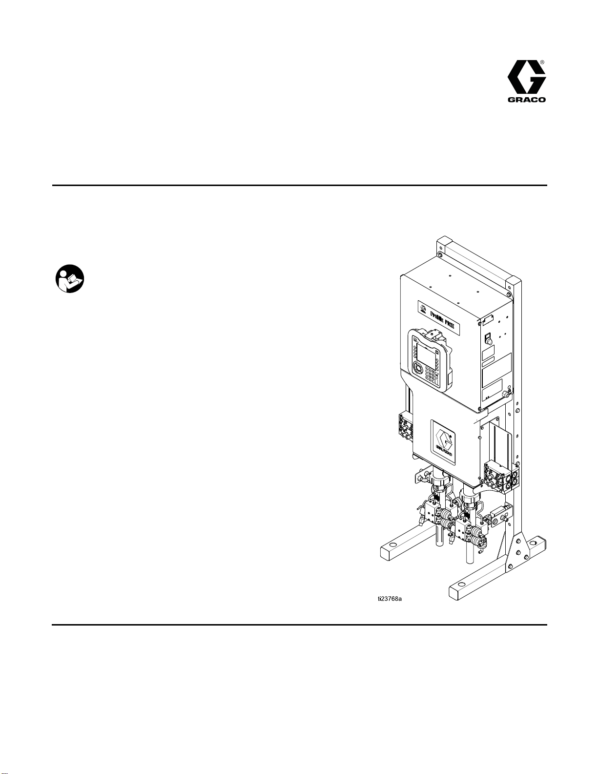
Repair-Parts
ProMix® PD2K Pr
Automatic Spr
Electronic positive displacement proportioner for fast-setting two-component materials. System for
automatic dispense, with Advanced Display Modules. For professional use only.
Important Safety Instructions
Read all warnings and instructions in this manual and in your
installation, operation, and associated component manuals.
Save these instructions.
See page 3
approvals information.
for model part numbers and
ay Applications
oportioner for
332709B
EN
PROVEN QUALITY. LEADING TECHNOLOGY.
Page 2

Contents
Models............................................................... 3
Related Manuals ................................................ 5
Warnings ........................................................... 6
Important Isocyanate (ISO) Information................ 9
Troubleshooting.................................................. 10
System Troubleshooting............................... 10
Error Code Troubleshooting.......................... 11
Power Barrier Board Diagnostics .................. 21
Isolation Board Diagnostics .......................... 22
Enhanced Fluid Control Module (EFCM)
Diagnostics .................................... 23
Pump Module Diagnostics ............................ 24
AdvancedDisplay Module Diagnostics........... 25
Notes ................................................................ 26
Electrica
l Schematics.......................................... 27
Optional Cables and Modules....................... 33
Repair................................................................ 34
Before Servicing .......................................... 34
Pressure Relief Procedure............................ 35
Repairing the Advanced Display Module
(ADM)............................................ 36
Servicing the Control Box ............................. 38
Servicing the Fluid Section ........................... 48
Notes ................................................................ 53
Parts.................................................................. 54
Proportioner Parts........................................ 54
Control Box Parts......................................... 57
Solenoid Manifold Parts................................ 60
Technical Data ...................................................61
Graco Sta
ndard Warranty.................................... 62
2
332709B
Page 3
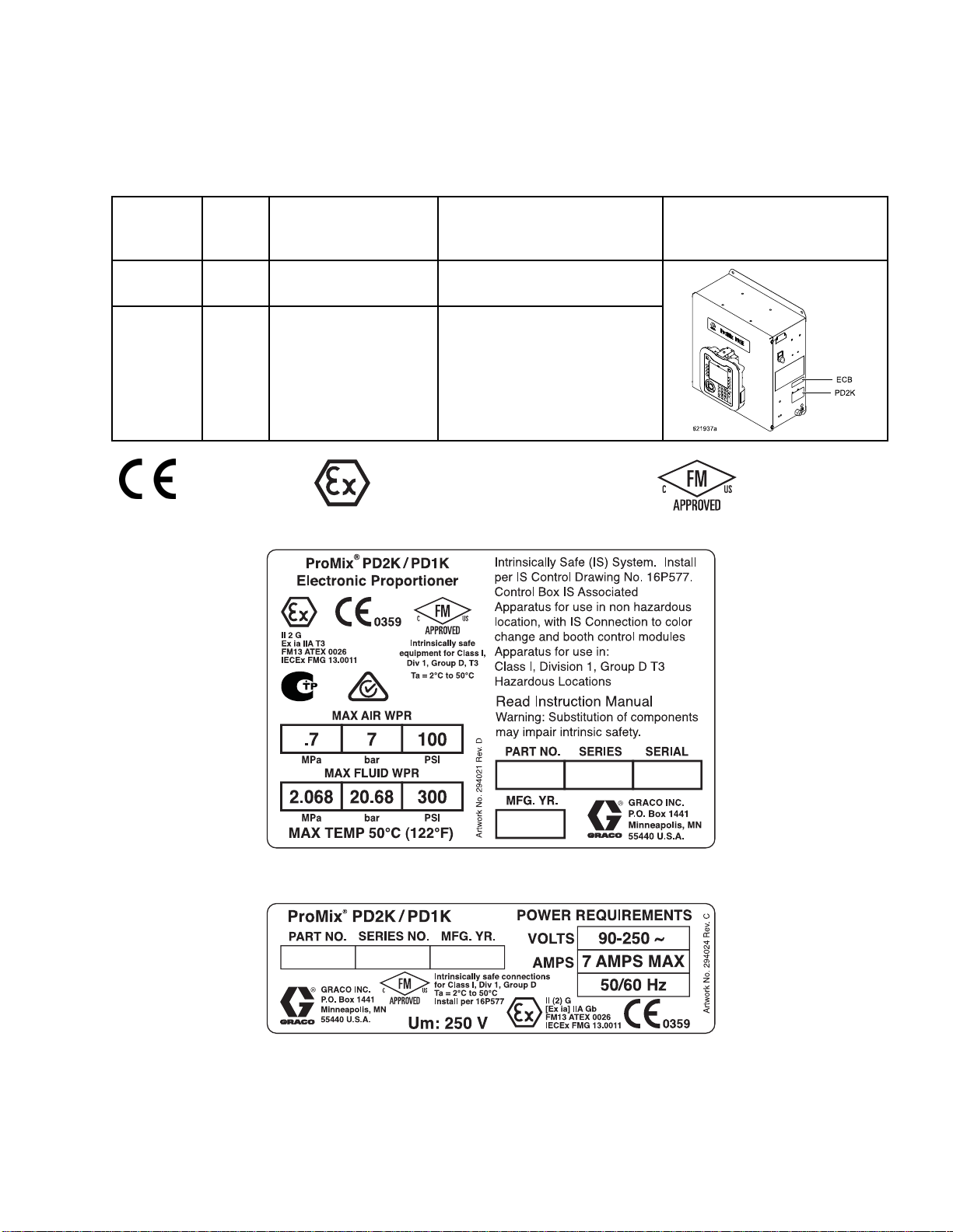
Models
Models
SeeFigs.1–7f
Part No.
AC1000
AC2000
0359
or component identification labels, including approval information and certification.
Series
A
A
Maximum Air Wo
Pressure
100 psi (0.7
7.0 bar)
100 psi (0.7 MPa,
7.0 bar)
MPa,
II 2 G
rking
Maximum Fluid
Pressure
300 psi (2.0
1500 psi (10.34 MPa,
68 MPa, 20.68 bar)
103.4 bar)
Working
Location of PD2K and
Electrical Control Box
(ECB) Labels
Figure 1 Model AC1000 (Low Pressure) Identification
Label
Figure 2 24M672 Control Box Identification Label
Continued on the next page.
332709B 3
Page 4
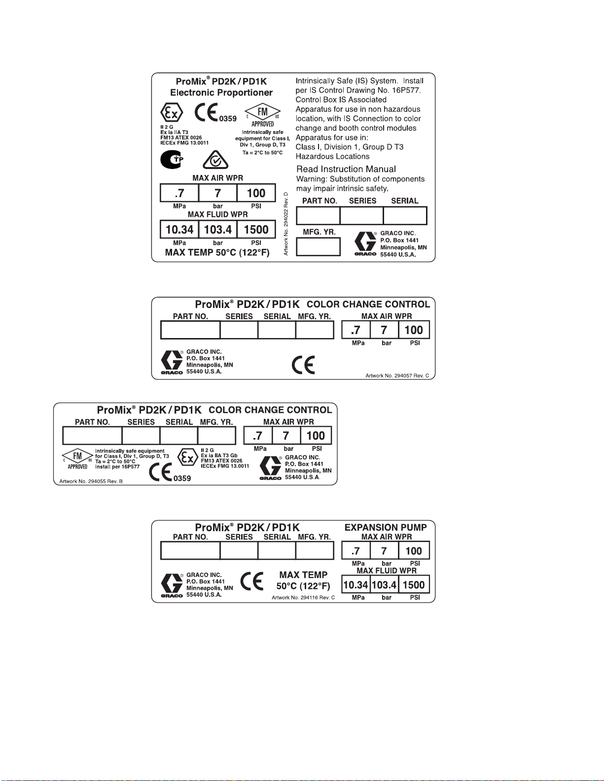
Models
Figure 3 Model AC2000 (High Pressure)
Identification Label
Figure 4 Non-Intrinsically Safe Color Change Control (Accessory) Identification Label
Figure 5 Intrinsically Safe Color Change Control
(Accessory) Identification Label
Figure 6 Pump Expansion Kit (Accessory) Identification Label
4
332709B
Page 5
Related Manuals
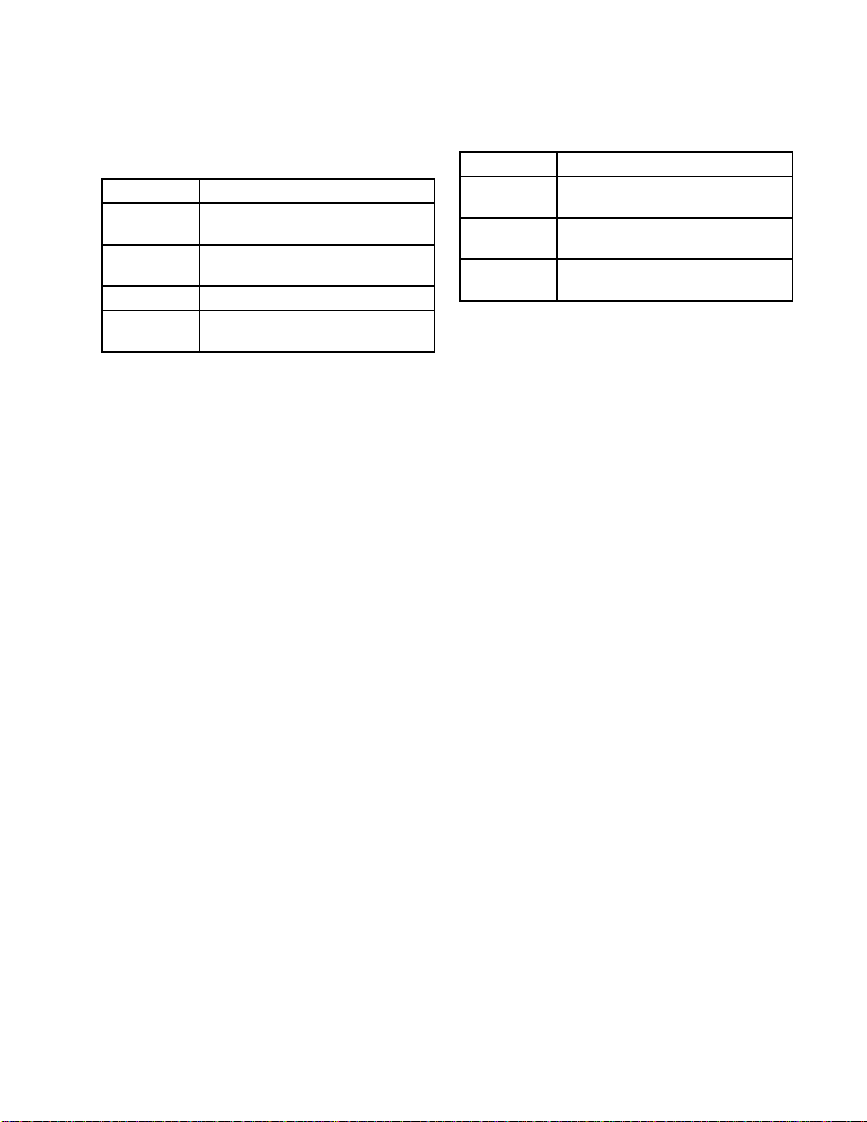
Related Manuals
Current manua
Manual No. Description
332458 PD2K Proportioner Installation
332564
332339 Pump Repair-Parts Manual
332454
ls are available at www.graco.com.
Manual, Automatic Systems
PD2K Proport
Manual, Aut
Color Chan
Manual
ioner Operation
omatic Systems
ge Valve Repair-Parts
Manual No. Description
332455
333282
332456 3rd and 4th Pump Kits
Color Change Kits InstructionsParts Manual
Remote Mix Ma
Instructio
Instructions-Parts Manual
ns-Parts Manual
nifold
332709B 5
Page 6
Warnings
Warnings
The following
exclamation p
risks. When th
Warnings. Pr
the body of th
warnings are for the setup, use, grounding, maintenance and repair of this equipment. The
oint symbol alerts you to a general warning and the hazard symbol refers to procedure-specific
ese symbols appear in the body of this manual or on warning labels, refer backtothese
oduct-specific hazard symbols and warnings not covered in this section may appear throughout
is manual where applicable.
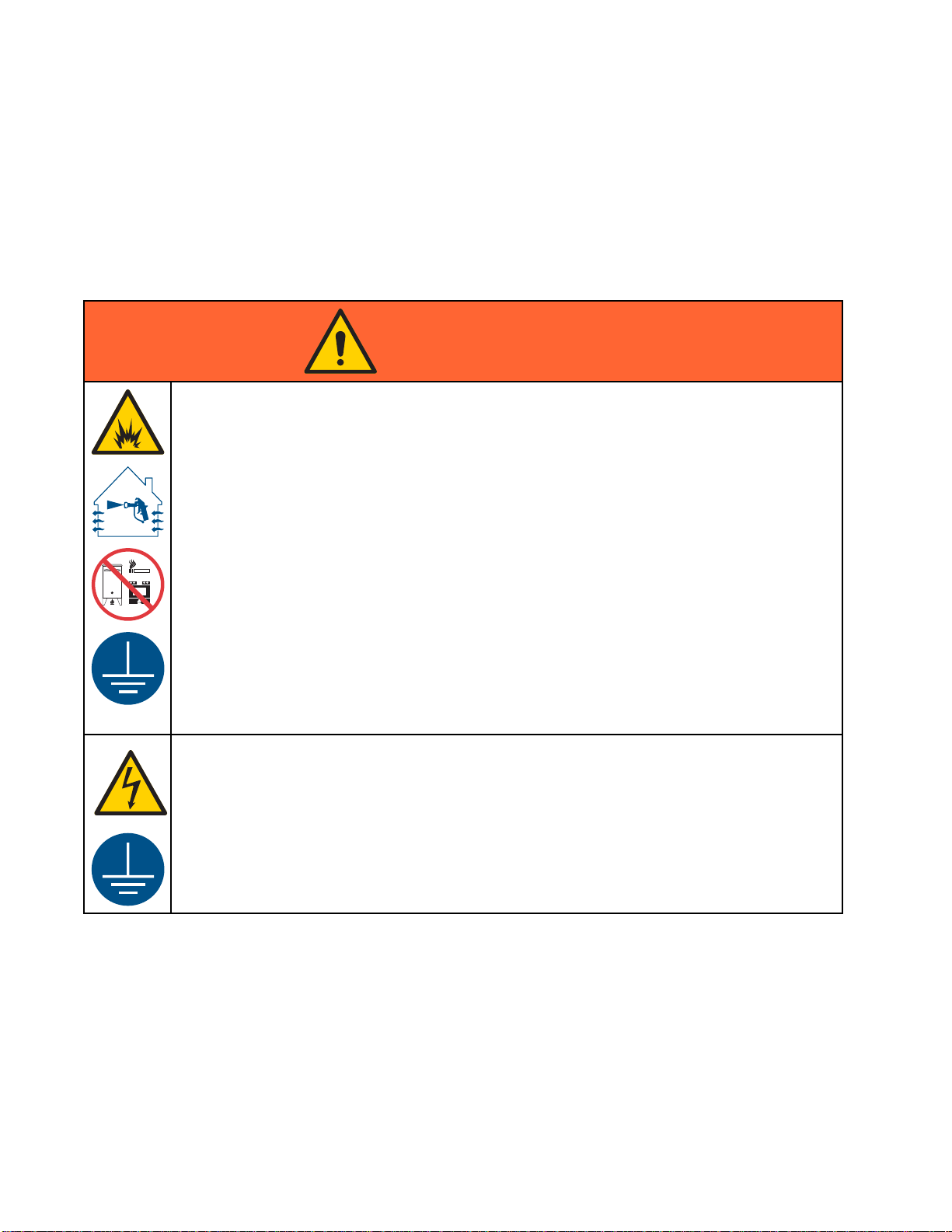
WARNING
FIRE AND EX
Flammable fumes, such as solvent and paint fumes, in work area can ignite or explode. To help
prevent fire and explosion:
• Use equipment only in well ventilated area.
• Eliminate all ignition sources; such as pilot lights, cigarettes, portable electric lamps, and
plastic drop cloths (potential static arc).
• Keep work
• Do not plug or unplug power cords, or turn power or light switches on or off when flammable
fumes are present.
• Ground all equipment in the work area. See Grounding instructions.
•Useonly
• Hold gun firmly to side of grounded pail when triggering into pail. Do not use pail liners unless
they are antistatic or conductive.
• Stop operation immediately if static sparking occurs or you feel a shock, Do not use
equipment until you identify and correct the problem.
• Keepaw
PLOSION HAZARD
area free of debris, including solvent, rags and gasoline.
grounded hoses.
orking fire extinguisher in the work area.
ELECTRIC SHOCK HAZARD
This equipment must be grounded. Improper grounding, setup, or usage of the system can
cause electric shock.
•Turn
• Connect only to grounded power source.
• All electrical wiring must be done by a qualified electrician and comply with all local codes
6 332709B
off and disconnect power at main switch before disconnecting any cables and before
icing or installing equipment.
serv
and regulations.
Page 7
INTRINSIC SAFETY
Warnings
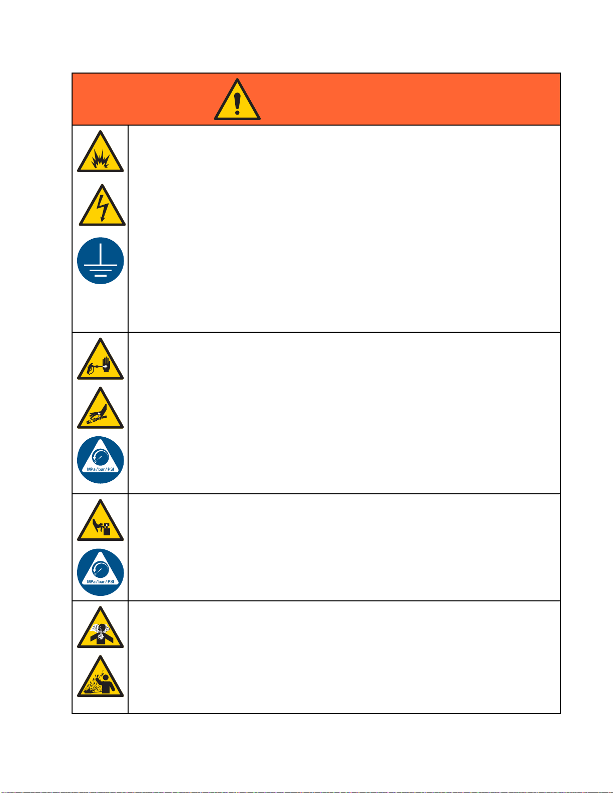
WARNING
Intrinsical
equipment wi
Follow local
• Be sure your installation complies with national, state, and local codes for the installation of
electrical apparatus in a Class I, Group D, Division 1 (North America) or Class I, Zones 1
and 2 (Europe) Hazardous Location, including all of the local safety fire codes (for example,
NFPA 33, NEC 500 and 516, OSHA 1910.107, etc.).
• To help prev
•Equipment
Safety. T
unit from
SKIN INJECTION HAZARD
High-pr
skin. Th
immedia
• Do not point dispensing device at anyone or at any part of the body.
•Donotp
• Do not stop or deflect leaks with your hand, body, glove, or rag.
• Follow the Pressure Relief Procedure when you stop dispensing and before cleaning,
checking, or servicing equipment.
•Tight
• Check hoses and couplings daily. Replace worn or damaged parts immediately.
ly safe equipment that is installed improperly or connected to non-intrinsically safe
ll create a hazardous condition and can cause fire, explosion, or electric shock.
regulations and the following safety requirements.
ent fire and explosion:
• Do not install equipment approved only for a non-hazardous location in a hazardous
location. See model ID label for the intrinsic safety rating of your model.
• Do not substitute system components as this may impair intrinsic safety.
that comes in contact with the intrinsically safe terminals must be rated for Intrinsic
his includes DC voltage meters, ohmmeters, cables, and connections. Remove the
the hazardous area when troubleshooting.
essure fluid from dispensing device, hose leaks, or ruptured components will pierce
is may look like just a cut, but it is a serious injury that can result in amputation. Get
te surgical treatment.
ut your hand over the fluid outlet.
en all fluid connections before operating the equipment.
332709B
MOVING PARTS HAZARD
Moving parts can pinch, cut or amputate fingers and other body parts.
• Keep clear of moving parts.
• Do not operate equipment with protective guards or covers removed.
•Pres
TOX
Tox
inh
• Read MSDSs to know the specific hazards of the fluids you are using.
•St
• Always wear chemically impermeable gloves when spraying, dispensing, or cleaning
surized equipment can start without warning. Before checking, moving, or servicing
pment, follow the Pressure Relief Procedure and disconnect all power sources.
equi
IC FLUID OR FUMES
ic fluids or fumes can cause serious injury or death if splashed in the eyes or on skin,
aled, or swallowed.
ore hazardous fluid in approved containers, and dispose of it according to applicable
idelines.
gu
equipment.
7
Page 8
Warnings
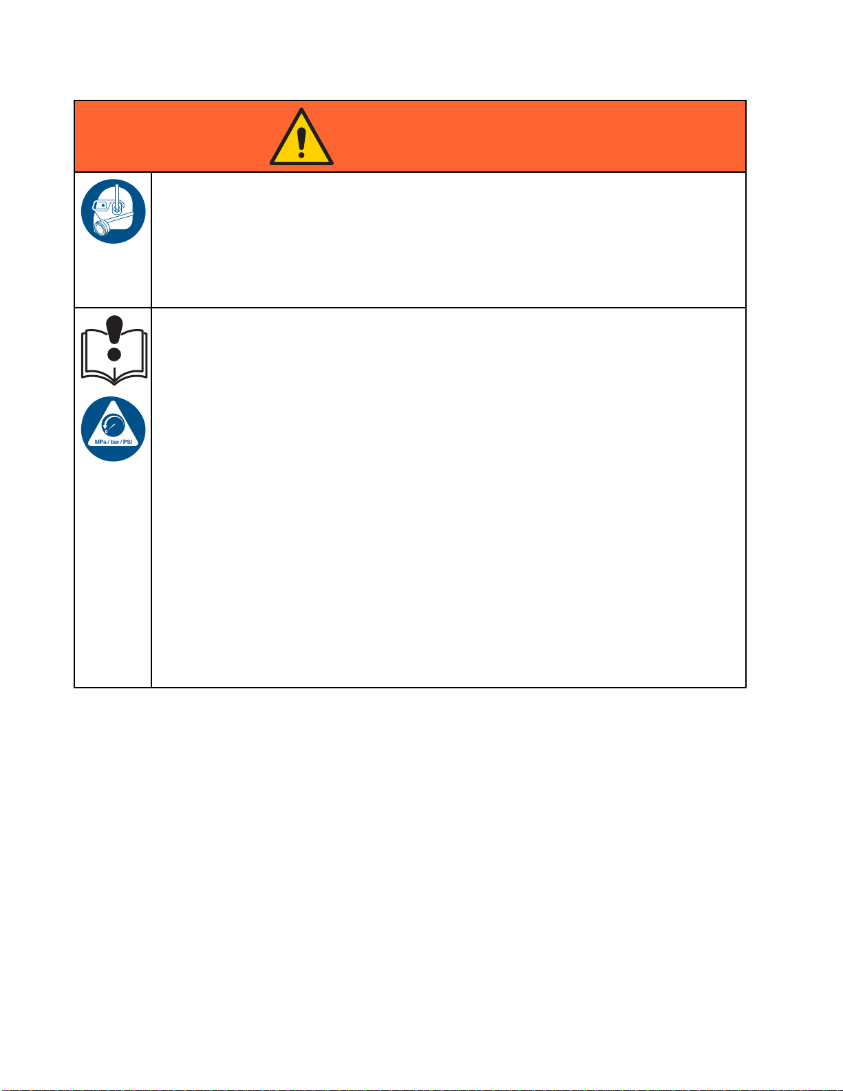
WARNING
PERSONAL PROTECTIVE EQUIPMENT
Wear appropriate protective equipment when in the work area to help prevent serious injury,
including eye injury, hearing loss, inhalation of toxic fumes, and burns. This protective
equipment includes but is not limited to:
•Protectivee
• Respirators, protective clothing, and gloves as recommended by the fluid and solvent
manufacturer.
EQUIPMENT MISUSE HAZARD
Misuse can cause death or serious injury.
• Do not operate the unit when fatigued or under the influence of drugs or alcohol.
• Do not exceed the maximum working pressure or temperature rating of the lowest rated
system component. See Technical Data in all equipment manuals.
•Usefluids
in all equ
informat
• Do not leave the work area while equipment is energized or under pressure.
• Turn off all equipment and follow the Pressure Relief Procedure when equipment is not in use.
•Checkeq
manufac
• Do not alter or modify equipment. Alterations or modifications may void agency approvals
and create safety hazards.
• Make sure all equipment is rated and approved for the environment in which youareusingit.
•Useequ
• Route hoses and cables away from traffic areas, sharp edges, moving parts, and hot surfaces.
• Do not kink or over bend hoses or use hoses to pull equipment.
•Keepc
• Comply with all applicable safety regulations.
yewear, and hearing protection.
and solvents that are compatible with equipment wetted parts. See Technical Data
ipment manuals. Read fluid and solvent manufacturer’s warnings. For complete
ion about your material, request MSDS from distributor or retailer.
uipment daily. Repair or replace worn or damaged parts immediately with genuine
turer’s replacement parts only.
ipment only for its intended purpose. Call your distributor for information.
hildren and animals away from work area.
8 332709B
Page 9
Important Isocy
anate (ISO) Information
Important Iso
Isocyanates (ISO) are catalysts used in two
component materials.
cyanate (ISO) Information
Isocyanate Conditions
Spraying or dispensing materials containing
isocyanates creates potentially harmful mists,
vapors, and atomized particulates.
Read and understand material manufacturer’s
warnings and material MSDS to know specific
hazards and precautions related to isocyanates.
Prevent inhalation of isocyanate mists, vapors,
and atomized particulates by providing sufficient
ventilation in the work area. If sufficient ventilation
is not available, a supplied-air respirator is required
for everyone in the work area.
To prevent contact with isocyanates, appropriate
personal protective equipment, including
chemically impermeable gloves, boots, aprons,
and goggles, is also required for everyone in the
work area.
Eventually a film will form on the surface and the ISO
will begin to gel, increasing in viscosity.
NOTICE
Partially c
the life of a
• Always use a sealed container with a desiccant
dryer in the vent, or a nitrogen atmosphere.
Never store ISO in an open container.
• Keep the ISO pump wet cup or reservoir (if
installed) filled with appropriate lubricant. The
lubricant creates a barrier between the ISO and
the atmosphere.
• Use only moisture-proof hoses compatible with
ISO.
• Never use reclaimed solvents, which may
contain moisture. Always keep solvent
containers closed when not in use.
• Always lubricate threaded parts with an
appropriate lubricant when reassembling.
NOTE: The amount of film formation and rate of
crystallization varies depending on the blend of ISO,
the humidity, and the temperature.
ured ISO will reduce performance and
ll wetted parts.
Keep Components A and B Separate
Cross-contamination can result in cured
material in fluid lines which could cause serious
injury or damage equipment. To prevent
cross-contamination:
• Never interchange component A and component
B wetted parts.
• Never use solvent on one side if it has been
contaminated from the other side.
Moisture Sensitivity of Isocyanates
Exposure to moisture (such as humidity) will cause
ISO to partially cure; forming small, hard, abrasive
crystals, which become suspended in the fluid.
Chang
Changing the material types used in your
equipment requires special attention to avoid
equipment damage and downtime.
•When
•Alw
•Che
•Wh
ing Materials
NOTIC
changing materials, flush the equipment
tiple times to ensure it is thoroughly clean.
mul
ays clean the fluid inlet strainers after
hing.
flus
ck with your material manufacturer for
mical compatibility.
che
en changing between epoxies and urethanes
polyureas, disassemble and clean all fluid
or
mponents and change hoses. Epoxies often
co
ve amines on the B (hardener) side. Polyureas
ha
tenhaveaminesontheA(resin)side.
of
E
332709B 9
Page 10

Troubleshootin
g
Troubleshooting
NOTE: Check all possible remedies before disassembling the system.
System Troubleshooting
Problem
Unit will not operate.
Pump output low on both strokes.
Pump output low on only one
stroke.
No output. Improperly installed dosing valves.
Cause Solution
Inadequate power supply.
Power switch is off.
Main power is shut off.
Exhausted fluid supply. Refill and reprime pump.
Clogged fluid outlet line, valves,
etc.
Fluid dried on piston rod. Disassemble and clean pump.
Inadequate power supply.
Exhausted fluid supply. Refill and reprime pump.
Clogged fluid outlet line, valves,
etc.
Worn piston packings.
Held open or worn dosing valves.
Worn piston packing.
See Technical Data, page 61.
Turn switch on.
Turn main power switch on.
Clear.
See pump manual. In future, stop
pump at bottom of stroke.
See Technical Data, page 61.
Clear.
Replace. See pump manual.
Check and repair. See pump
manual.
Replace. See pump manual.
Check solenoid connections to
valves. See pump manual.
Pump operates erratically.
Exhausted fluid supply. Refill and reprime pump.
Held open or worn dosing valves.
Worn piston packing.
Check and repair. See pump
manual.
Replace. See pump manual.
10 332709B
Page 11

Troubleshootin
g
Error Code Tro
System errors alert you of a problem and help
prevent off-ratio spraying. There are three types:
Advisory, Deviation, and Alarm.
An Advisory r
clear itself
A Deviation records an error in the system but does
not shut down the equipment. The deviation must be
acknowledged by the user.
If an Alarm occurs, operation stops.
If any of th
• Alarm buzzer sounds (unless in silent mode).
• Alarm popup screen shows the active alarm code.
• Status bar on the Advanced Display Module shows
the active alarm code.
• Alarm is saved in the date/time stamped log.
Code
B9A0 Advi-
ecords an event in the system, and will
after 60 seconds.
e three types occur:
Type Description Problem
sory
ubleshooting
Volume
Rollove
Current
Batch counter for
rA
material A rolled over.
NOTE: When an error occurs be sure to determine
the code before resetting it. If you forget which code
occurred, the Errors screen displays the 200 most
recent errors, with date, time, and description.
NOTE: In some
is shown as th
applicable
display wil
last digit i
Cause Solution
The tota
reached
capable
starte
error codes listed below, a # symbol
e last digit. This symbol represents the
pump number, which can vary. The unit’s
l show the applicable pump number as the
n the code.
lizer has
maximum
value and
doveratzero.
n/a
B9AX Advi-
sory
B9B0 Advi-
sory
B9BX Advi
sory
B9D#
Advisory
-
Volume
Rollover A
Lifetime
Volume
Rollover B
Current
me
Volu
over B
Roll
time
Life
Volume
Rollover
Pump #
Grand total counter for
material A rolled over.
counter for
Batch
ial B rolled over.
mater
Grand total counter for
material B rolled over.
Grand total counter for
pump # rolled over.
The totalizer has
reached maximum
capable value and
started over at zero.
The totalizer has
reached maximum
capable value and
started over at zero.
otalizer has
The t
hed maximum
reac
ble value and
capa
ted over at zero.
star
The totalizer has
reached maximum
capable value and
started over at zero.
n/a
n/a
n/a
n/a
332709B
11
Page 12

Troubleshootin
g
Code
B9S0
B9SX
CAC#
CA0X
CADX
Type Description Problem
Advisory
Advisory
Alarm
Alarm
Alarm
Volume
Rollover
Solvent
Current
Volume
Rollover
Solvent
Lifetime
Comm.
Error Color
Change #
Comm.
Error ADM
Comm.
Error Fluid
Module
Batch counter
solvent rolle
Grand total counter for
solvent rolled over.
System does not detect
the Color Change
Module #.
System does not detect
the Advanced Display
Module.
System does not
detect the Enhanced
Fluid Control Module
(EFCM).
for
dover.
Cause Solution
The totalizer has
reached maximum
capable value and
started over at zero.
The totalize
reached maxi
capable valu
started over
This communication
error indicates that
the network has lost
communication with
the Color Change
Module #.
This comm
error ind
the Netwo
communic
the Adva
Module.
This communication
error indicates that
the Network has lost
communication with
the EFCM.
r has
mum
eand
at zero.
unication
icates that
rk has lost
ation with
nced Display
n/a
n/a
Check CAN cable
connections to
the Color Change
Module # and any
interconnected
modules.
Check CAN cable
connecting ADM to the
EFCM.
Check CAN cables
connecting ADM to
the EFCM. Replace
Cable or EFCM as
necessary.
CDC#
Alarm Duplic
Color
Chang
ate
e#
System detects two or
more identical Color
Change Modules.
More than one Color
Change Module with
the same address
is connected in the
system .
Check the system
and remove the extra
color change module.
Re-address one of the
color change boards.
2
1
332709B
Page 13

Troubleshootin
g
Code
CDDX
DA0#
DE0#
Type Description Problem
Alarm Duplicate
Fluid
Module
Alarm Exceeded
Max Flow
Pump #
Alarm Leak
Detecte
Pump #
System sees tw
or more identi
Enhanced Flui
Control Modul
EFCM).
Pump was driven to
its maximum allowed
speed.
This is a
d
test fai
pump can
pressur
Test Pressure.”
“Stall
ult after 30
Will fa
second
o
cal
d
es
manual stall
lure when the
not build
etothetarget
s.
Cause Solution
tating,
thout
FCM
nthe
Check the syst
and remove the
EFCM.
Inspect system for
leaks.
Verify that the pump
is being supplied with
material.
Reduce nozzle size
to create more
restriction. Reduce
paint pressure to lower
the flow rate.
Make sur
and down
line are
al.
materi
Determine if leak is
external or internal
by visually inspecting
the system for fluid
leakage. Fix all loose
or worn hoses, fittings,
and seals. Inspect
all valve seats and
needles for wear, and
replace worn piston or
throat seals.
More than one E
is connected i
system.
System has a leak
or open valve that is
allowing unrestricted
flow.
Pump is cavi
cycling wi
restricti
Viscosit
too thin f
No mater
pump or l
Leak in the system.
on.
y of material is
or nozzle size.
ial in the
ine.
em
extra
e the pump
stream color
loaded with
DF0#
Alar
m
No Stall Up
Pump #
Pump failed the stall
test; did not stall on the
upstroke.
Valve failure, seal
failure, worn rod or
cylinder.
ace inlet and
Repl
let valve and
out
l for up stroke.
sea
lace piston and
Rep
oat seals. Replace
thr
and cylinder as
rod
cessary.
ne
332709B 13
Page 14

Troubleshootin
g
Code
DG0#
DH0#
DK0#
EAUX Advi-
Type Description Problem
Alarm
Alarm
Alarm Position
sory
No Stall
Down
Pump #
No Stall
Pump #
Pump #
USB Busy USB driv
Pump failed th
test;didnots
downstroke.
Pump failed the stall
test; did not stall on
either the upstroke or
the downstroke.
The pump was
detected to be out
of position.
d, download is
inserte
in progr
estall
tall on the
e has been
ess.
Cause Solution
Valve failure
failure, worn
cylinder.
Valve failure, seal
failure, worn rod or
cylinder.
Indicat
is uploa
downloa
,seal
rod or
es USB port
ding or
ding data.
Replace inlet and
outlet valve and seal
for down stroke.
Replace piston and
throat seals. Replace
rod and cylinder as
necessary.
Replace inle
outlet valv
for up and do
strokes. Re
piston and t
seals. Rep
rod and cyl
necessary
Re-enable pump
power to reset pump.
Make sure inlet supply
pressure is not too
high.
Wait for
t and
e and seal
wn
place
hroat
lace
inder as
.
USB Idle.
EB00 Record
EBH#
EBUX Record
EC00
Recor
ord
Rec
d
Stop
Button
Pressed
Home
ete
Compl
Pump #
USB
drive was
removed.
Setup
Value(s)
Changed
Recordofastopbutton
press.
Record of pump
homing is complete.
USB drive was
removed while
downloading or
uploading.
Record of changing
setup variables.
Indicates system stop
key on ADM was
pressed.
ication on the
An ind
ay that the pump
displ
eted the home
compl
ion
funct
Downloading/uploading data on USB was
interrupted by the USB
device being removed.
icates date and time
Ind
n setup values
whe
e changed.
wer
n/a
ion required.
No act
Replace the USB
device and begin
process again.
n/a
4
1
332709B
Page 15

Troubleshootin
g
Code
EF0#
EF1#
Type Description Problem
Alarm Timeout
Startup
Pump #
Alarm Timeout
Shutdown
Pump #
Pump tried but was not
able to move to the
home position within
a specified amount of
time.
Pump tried but was not
able to move to the
park position within a
specified amount of
time.
Cause Solution
Pump dose valves did
not actuate.
Motor could not drive
pumps and linear
actuator.
Pump stroke length
is shortened by
mechanical system
tolerance.
Pump dose valves did
not actuate.
Pump is fi
thick pa
not driv
end of s
or driv
damage
lled with
int and could
epistonto
troke. Motor
eiswornor
d.
Verify air pre
to solenoid va
Verify the val
actuating.
Verify motor is driving
the pump.
Verify corr
assembly of
actuator an
piston rod
manual.
Visually inspect valves
to ensure they are
operating properly;
verify they have air
pressure above 85 psi
(0.6 MPa, 6.0 bar).
Observe
drive as
verify t
genera
ssure
lves.
ves are
ect
linear
d pump
s. See pump
motor and
sembly to
hat the motor is
ting force.
EL00 Record
EM00 Record
EMIX Advi
0
EQU
EQU1
-
sory
Advisory
Record
System
Power On
em
Syst
rOff
Powe
Pump Off
Idle
USB
USB Sys.
Settings
Downloaded
Record of power cycle
(ON).
rd of power cycle
Reco
).
(OFF
umps are not
The p
red and are
powe
le to move.
unab
download
USB
ocess completed,
pr
ive may be removed.
dr
Settings were
downloaded to USB
drive.
Indicates date and
time when system was
started.
Indicates date and
time when system was
turned off.
power was
Pump
ed off or an error
turn
rred.
occu
atransferis
Dat
mpletedtotheUSB
co
vice.
de
User installed USB
device in ADM USB
port.
n/a
n/a
Start pumps by
pressing pump start
key on Advanced
Display module.
ove USB device
Rem
om ADM.
fr
n/a
332709B 15
Page 16

Troubleshootin
g
Code
EQU2
EQU3
EQU4
EQU5
ES00
EVUX Advi-
F1F#
Type Description Problem
Record
Record
Record
Record
Advisory
sory
Alarm Flow Low
USB Sys.
Settings
Uploaded
USB Custom Lang.
Downloaded
USB
Custom
Lang.
Uploaded
USB Logs
Downloaded
Factory
Defaults
USB
Disabled
Fill Pump #
Settings were
uploaded from
drive.
Custom Language was
downloaded to USB
drive.
Custom Language was
uploaded from USB
drive.
Data logs were
downloaded to USB
drive.
Record of defaults
being loaded.
USB drive has been
inserted, downloading
is disabled.
There has been no/low
flow during a fill pump
operation.
USB
Cause Solution
User installe
device in ADM U
port.
User installed USB
device in ADM USB
port.
User installed USB
device in ADM USB
port.
User inst
device in
port.
Configuration of
system is blocking
data transfer.
There is a restriction
on the outlet side of the
pump or color stack.
dUSB
SB
alled USB
ADM USB
n/a
n/a
n/a
n/a
n/a
Change configuration
to enable USB
download function.
Make sure there are
no restrictions in the
color stack and that
thedumpvalveis
actuating.
F1S#
F#
F6
Alarm Flow Low
Purge
Pump #
Alarm Press.
Sens.
Removed
Inlet #
There has been no flow
or low flow during a
pump purge operation.
No inlet pressure
transducer is detected
when the system is
expecting one.
k viscosity
Thic
t requires more
pain
sure to pump.
pres
Restriction in the outlet
side of the pump or
color stack resulting in
the solvent flow being
too low.
Disconnected
transducer.
ease non-mix
Incr
sure if necessary
pres
eate flow during
to cr
ll function.
the fi
Make sure there are
no restrictions in the
system. Increase
non-mix pressure if
necessary to create
flow during the purge
function.
rify transducer
Ve
connected
is
roperly. Replace if
p
econnecting does not
r
liminate the alarm.
e
16 332709B
Page 17

Troubleshootin
g
Code
F7D#
F7S1
F7S2
F8D1 Alarm Flow Not
Type Description Problem
Alarm Flow
Detected
Pump #
Alarm Flow
Detected
Solvent
Gun
Alarm Flow
Detected
Solvent Mix
Detected
Thepumpflow
exceeded 20 cc
flow coming int
mode.
One of the solvent flow
switches is indicating
unexpected solvent
flow.
The system detects
both solvent flow
switches open at the
same time.
No Flow while mixing.
/min
oIdle
Cause Solution
There is a leak in the
system or the gun was
open when the system
went into Idle mode.
Solvent flow switch is
stuck in flow position.
There is a le
the solven
valve.
The EFCM is
damaged.
One or bo
solvent
are stuc
positio
Restriction in the outlet
side of the pump or
color stack.
ak through
t cutoff
th of the
flow switches
kintheflow
n.
Verify there a
leaks in the sy
Make sure the a
switch is actu
properly. Do
trigger the g
atomizing ai
Clean or replace
switch.
Check for leaks and
repair valve.
Unplug both
connectors on the
EFCM.Ifalarmclears,
replace the EFCM.
Clean or
switch.
Make sure there are
no restrictions in the
system.
re no
stem.
ir flow
ating
not
un without
r.
replace
F9D#
MMUX Advi
F#
P1
P2F#
P3D#
Alarm Flow
sory
Alarm Pressure
De
on
ti
Deviation
-
via-
Unstable
Pump #
Maint. USB
Logs Full
Low Inlet
Pump #
essure
Pr
wInlet
Lo
ump #
P
Pressure
High Outlet
Pump #
Thepumpflowrate
did not stabilize while
entering Idle mode.
USBmemoryismore
than 90% full.
The inlet pressure on
pump # is less than
the user-entered alarm
limit.
e inlet pressure on
Th
mp # is less than the
pu
ser-entered deviation
u
imit.
l
The outlet pressure
on pump # is greater
than the user entered
deviation limit.
tflowrateisset
Targe
o.
to zer
Potential leak in the
system.
Configuration
parameter on system
is enabled to generate
this advisory.
arget flow rate.
Set a t
Check the system for
leaks and run manual
stall test.
Complete download to
ensure no data is lost.
Increase inlet
pressure.
crease inlet
In
essure.
pr
Relieve system
pressure.
332709B
17
Page 18

Troubleshootin
g
Code
P3F#
P4D#
P4F#
P6D#
P9D#
Type Description Problem
Deviation
Alarm Pressure
Alarm Pressure
Alarm Press.
Alarm Press.
Pressure
High Inlet
Pump #
High Outlet
Pump #
High Inlet
Pump #
Sens.
Removed
Outlet #
Sens.
Failed
Outlet #
The inlet pressure
on pump # is greater
than the user-entered
deviation limit.
The outlet pr
pump # is grea
the user ente
limit.
The inlet pressure on
pump # is greater than
the user-entered alarm
limit.
No outlet pressure
transducer is detected
when the system is
expecting one
Outlet pressure
transducer has failed.
essure on
ter than
red alarm
Cause Solution
Decrease inlet
pressure.
Relieve syst
pressure.
Decrease inlet
pressure.
Disconnected
transducer.
Outlet pressure
transducer has failed
orthepressureis
above the readable
range.
Verify tra
is connect
properly
reconnec
eliminat
Relieve system
pressure. Verify
connections, or
replace if reconnecting
does not eliminate the
alarm.
em
nsducer
ed
. Replace if
ting does not
e the alarm.
P9F#
QADX
QBDX
Alarm Press.
Sens.
Failed Inlet
#
Alarm
Alarm
Differential
Pressure A
Over B
Differential
Pressure B
Over A
Inlet pressure
transducer has failed.
Low differential
pressure. This alarm is
active only during Mix
mode.
High differential
pressure. This alarm is
active only during Mix
mode.
Inlet pressure
transducer has failed
orthepressureis
above the readable
range.
isaleakonthe
There
.
Bside
The B side pump is
cavitating.
There is a leak on the
Aside.
he A side pump is
T
avitating.
c
Relieve system
pressure. Verify
connections, or
replace if reconnecting
does not eliminate the
alarm.
Check the system
for internal and
external leaks on
all catalyst manifolds
and plumbing.
ck paint supply on
Che
B side, increase
the
nt supply pressure.
pai
Check the system
for internal and
external leaks on
all color manifolds and
plumbing.
Check paint supply on
the A side, increase
paint supply pressure.
18 332709B
Page 19

Troubleshootin
g
Code
QPD1
SND1
SPD1
Type Description Problem
Deviation
Alarm Mix Fill
Alarm
Potlife
Expired
Incomplete
Gun Pur
Incomp
ge
lete
Potlife time h
expired befor
system has mov
the required a
of material (
volume) thro
mixed materi
The system timed out
before the mix fill cycle
loaded the gun with
mixed material.
The system timed out
without reaching the
user-specified volume
of solvent for a purge.
as
ethe
ed
mount
potlife
ugh the
al line.
Cause Solution
Purge process was not
completed.
Solvent supply shut off
or empty.
Mix manifold not set to
spray position.
Spray gun was not
triggered.
Restrictions in mixer,
manifold, or spray gun.
Target flow rate is set
to zero.
Solven
workin
Solvent flow is too low
to actuate the solvent
switch.
t flow switch not
g.
Make sure purge
process is completed.
Verify solvent supply
is available and on,
supply valves are
open.
Set manifold to spray.
Allow flow through gun
during fill process until
the fill complete LED
stops flashing.
Fix restrictions.
Set a target flow rate.
Replace switch.
Increase solvent
pressure to drive a
high purge flow rate
i-
WSUX
WX00 Alarm
XUD
W
WXUU Advi-
Adv
sor
dvi-
A
ory
s
sory
y
USB
Config. Err.
ftware
So
rrors
E
USB
Download
Err.
USB
Upload Err.
USB configuration
file does not match
expected, checked on
startup.
An unexpected
software error has
occurred.
n error occurred
A
hile downloading to
w
he USB drive.
t
An error occurred
while uploading from
the USB drive.
Gun is not triggered. Operator must
continue flushing
for configured time,
until the booth control
indicates purge is
completed.
Valve stuck or broken. Replace valve.
A software update
was not completed
successfully.
ser installed
U
ncompatible USB
i
evice in ADM USB
d
ort.
p
User installed
incompatible USB
device in ADM USB
port.
Reinstall software.
ll Graco Technical
Ca
upport.
S
epeat process with
R
ompatible USB
c
evice.
d
Repeat process with
compatible USB
device.
332709B 19
Page 20

Troubleshootin
Maintenance Error Codes
g
Perform the re
Code
END#
ENS0
ENT#
MAD#
MAT#
MEB#
MED#
MEF#
MEG#
MES#
MFF#
MFS0
quired maintenance if the following codes occur.
Type Name Description
Record
Record
Record
Advisory
Advisory
Advisory
Advisory
Advisory
ry
Adviso
Advisory
Advisory
sory
Advi
Calibration P
Calibration Solvent
Meter
Calibration Stall Test
Pump #
Maint. Out
Maint. Stall Test
Pump #
Maint. Valve Catalyst
(B) #
Maint. V
Maint. Valve Inlet #
Maint. Valve Gun #
.ValveSolvent
Maint
#
Maint. Meter Flow # Maintenance is due on flow meter.
Maint. Meter Solvent
ump #
let Pump #
alve Outlet #
A calibration test was run on the pump.
A calibration test was run on the solvent meter.
A stall test was completed successfully on pump #.
Maintenance is due on pump.
Maintenance stall test is due on pump.
Maintena
Maintenance is due on outlet valve.
Maintenance is due on inlet valve.
Mainte
Maintenance is due on solvent valve.
tenance stall test is due on solvent meter.
Main
nce is due on catalyst valve.
nance is due on gun valve.
MGH
MGP0
0
Advisory Maint. Filter Fluid
Advisory Maint. Filter Air
ntenance is due on fluid filter.
Mai
Maintenance is due on air filter.
20 332709B
Page 21

Power Barrier Board Diagnostics
Troubleshootin
g
Figure 7 Power Barrier Board
Table 1 . Power Barrier Board Diagnostics
ID
D4
D5
F3 Fuse, 400 mA, 250 V
F4 Fuse, 400 mA, 250 V
J4
J5
Component or Indicator
LED (green) IS Power
LED (green)
Connector
Connector +12 Vdc intrinsically safe power output
332709B
Function
Power
If either F3 or F4 is blown, there is no power
to the IS location. D4 is out.
24 Vdc power input
21
Page 22

Troubleshootin
g
Isolation Board Diagnostics
Figure 8 Isolation Board
Table 2 . Isolation Board Diagnostics
ID
D6
D7
D8
D14
J1
J2
J3
4
J
S1 Pushbutton Switch For Non IS connectors. If switch S1 is off, yellow LED (D14) is
S2 Pushbutton Switch For Intrinsically Safe connectors. If switch S2 is off, yellow LED
Compo
LED (yellow) IS Communication
LED (green) IS Power
LED
LED (yellow) Non-IS Communication
Connector Non-IS, Gateway
Co
Connector Intrinsically Safe, Barrier Board
Connector Intrinsically Safe, Optional Color Change Module
nent or Indicator
(green)
nnector
Function
-IS Power
Non
n-IS, Optional Color Change Module
No
steady on. Push switch to turn switch on.
(D6) is steady on. Push switch to turn switch on.
2
2
332709B
Page 23

Troubleshootin
g
Enhanced Flui
Figure 9 Enhanced Fluid Control Module
Table 3 . Enhanced Fluid Control Module Diagnostics
d Control Module (EFCM) Diagnostics
ID
1 25 pin connector Pump 1 Module
2 25 pin connector Pump 2 Module
3 25 pin connector
4 25 pin connector
5
6 12 pin connector
7
8 5 pin connector
9 5 pin connector Advanced Display Module
10 5 pin connector 24 Vdc Input
CPLD (D37) LED (orange)
POW (D19) LED (green)
CAN (D69) LED (yellow) Communication.
ERR (D38) LED (red) Blinks an error code. If the LED is on steady,
Component or Indicator
12 pin connector
12 pin connector
Function
Pump 3 Module (accessory)
Pump 4 Module (accessory)
Multiple purpose I/O
Multiple purpose I/O
Multiple purpose I/O
24 Vdc Power/CAN (Communication Barrier)
Heartbeat
Power
the system is down. Cycle power.
332709B 23
Page 24

Troubleshootin
g
Pump Module Diagnostics
Figure 10 Pump Module
Table 4 . Pump Module Diagnostics
ID
1 25 pin connector
2 5 pin connector Pump connection
3 5 pin connector Motor encoder connection
4 5 pin connector Pump Inlet Transducer
5
6 4 pin connector Not used
7 8 pin connector
8 4 pin connector
9
10
11
24V
48V
Component or Indicator
5 pin connector
LED (red) Pump Up Valve Output
LED (red) Pump Down Valve Output
LED (red)
LED (green)
LED (green)
Function
Input from EFCM
Pump Outlet Transducer
Dose Valve Solenoids
48 Vdc Input Power and fan connection
Not used
24 Vdc power supplied
48 Vdc power supplied
4
2
332709B
Page 25

Advanced Display Module Diagnostics
Troubleshootin
g
Figure 11 Advanced Display Module
Table 5 . Advanced Display Module Diagnostics
ID
D1
D6
J1 8 pin connector Token port
J2 8 pin
J3 5 pin connector
J7 5 pin connector
Compone
LED (yellow/green) Green: USB inserted
LED (red/yellow/green) Green: Power
nt or Indicator
connector
Function
Yellow
Yello
Red: Error
USB port
Lig
CAN power/communication port
: USB communication
w: Communication
ht tower (accessory)
332709B 25
Page 26

Notes
Notes
26 332709B
Page 27

Electrical Sche
matics
Electrical Sc
hematics
NOTE: The electrical schematic illustrates all possible
wiring expansions in a ProMix PD2K system. Some
components shown are not included with all systems.
NOTE: See Optional Cables and Modules, page 33 for
a list of cable options.
RELAY
(16U820)
16W159
BREAKOUT MODULE PUMP 2
BREAKOUT MODULE PUMP 4
POWER MODULE
(24R257)
16W159
16W159
(24N527)
(24N527)
SPLITTER
(16P243)
4
CABLE (16T659)
CABLE (16T659)
CABLE (16T659)
CABLE (16T659)
(24P658)
ENCODER AND MOTOR
(16P036, 16P037)
WIRE HARNESS
(24P684, 24P685)
PUMP INLET
TRANSDUCER
(16P289, 16P290)
PUMP OUTLET
TRANSDUCER
(16P289, 16P290)
PUMP V/P FOR
FLUID REG.
UP
DOWN
(16P812)
SOLENOID
MAC SERIES 46
FLOW SENSOR
(120278)
OR G3000 METER
(239716, 258718
16M510, 16M519)
(24P658)
ENCODER AND MOTOR
(16P036, 16P037)
WIRE HARNESS
(24P684, 24P685)
PUMP INLET
TRANSDUCER
(16P289, 16P290)
PUMP OUTLET
TRANSDUCER
(16P289, 16P290)
PUMP V/P FOR
FLUID REG.
UP
DOWN
(16P812)
SOLENOID
MAC SERIES 46
FLOW SENSOR
(120278)
OR G3000 METER
(239716, 258718
16M510, 16M519)
POWER IN
FAN
FAN
2 POSITION
SWITCH
(16U725)
CABLE
16T658
LINE FILTER
(16V446)
CABLE
16H078
TERMINAL BLOCK
(114095)
(24N527)
BREAKOUT MODULE PUMP 1
(24N527)
BREAKOUT MODULE PUMP 3
24V
POWER
SUPPLY
(16T660)
48V-10A POWER SUPPLY
TERMINAL BLOCKS WITH FUSES
16W159
FAN
(24P658)
ENCODER AND MOTOR
(16P036, 16P037)
WIRE HARNESS
(24P684, 24P685)
PUMP INLET
TRANSDUCER
(16P289, 16P290)
PUMP OUTLET
TRANSDUCER
(16P289, 16P290)
PUMP V/P FOR
FLUID REG.
UP
DOWN
(16P812)
SOLENOID
MAC SERIES 46
FLOW SENSOR
(120278)
OR G3000 METER
(239716, 258718
16M510, 16M519)
FAN
(24P658)
ENCODER AND MOTOR
(16P036, 16P037)
WIRE HARNESS
(24P684, 24P685)
PUMP INLET
TRANSDUCER
(16P289, 16P290)
PUMP OUTLET
TRANSDUCER
(16P289, 16P290)
PUMP V/P FOR
FLUID REG.
UP
DOWN
(16P812)
SOLENOID
MAC SERIES 46
FLOW SENSOR
(120278)
OR G3000 METER
(239716, 258718
16M510, 16M519)
Figure 12 Electrical Schematic, Sheet 1
INTEGRATION
GATEWAY
3
AWI
GATEWAY
(24R910)
CABLE (15V206)
2
CABLE
3
16T072
CAN
IS BOARD
(24M485)
CABLE
(16T280)
BARRIER
BOARD
(248192)
065161, 065159
5
CABLE
(121227)
5
(121227)
CABLE
3
(121001)
6
(24N935)
MODULE 1
COLOR CHANGE
CABLE
2
(15V206)
GCA
MODULE
EFCM
(24N913)
FLOW RATE ANALOG IN
FLOW RATE ANALOG IN
1
CABLE (16V429)
2
CABLE
(15V206)
6
(24N935)
MODULE 2
COLOR CHANGE
FLOW RATE ANALOG IN
FLOW RATE ANALOG IN
2
CABLE
(15V206)
6
6
6
(24N935)
(24N935)
MODULE 3
COLOR CHANGE
COLOR CHANGE
CABLE
2
(15V206)
GUN TRIGGER INPUTS
119159
119159
119159
119159
SOLENOID (121324)
PRESSURE SW (121323)
SOLVENT CUTOFF (121324)
SWITCH (120278)
SWITCH (120278)
SOLVENT METER (258718)
SAFETY INTERLOCK SWITCH
3
ADVANCED
CABLE
DISPLAY MODULE
(121003)
CABLE
1
(24N935)
MODULE 4
MODULE 5
CATALYST CHANGE
CABLE
2
(15V206)
(24E451)
COLOR CHANGE MODULE 7
(24R219)
COLOR CHANGE MODULE 8
(24R219)
(16V426)
BOOTH CONTROL (24M731)
HAZARDOUS LOCATION
NON-HAZARDOUS LOCATION
INTERFACES
SOLVENT
6
MODULE 6
CATALYST CHANGE
GFB
FLOW
INPUTS
LIGHT
TOWER
(15X472)
7
7
(24N935)
CABLE
1
(16V426)
332709B
27
Page 28

Electrical Sche
matics
SPLITTER
(16P243)
UNUSED
UNUSED
POWER
SUPPLY
(16T660)
L (BROWN)
N03 N03
2 POSITION
SWITCH
(16U725)
N04 N04
CABLE
(16T658)
L N
LINE
FILTER
(16V446)
L GRND N
CABLE
(16H078)
L N GRND
TERMINAL
BLOCK
(114095)
L N GRND
345
24V
2
1
UNUSED
GRND (GRN/YEL)
N (BLUE)
CABLE (16V429)
1
CONTINUED ON PAGE 3
2
3
CABLE
(15V206)
1 2 3 4 5
CAN IS BOARD
2
(NON IS)
(IS)
4
(24M485)
1 2 3 4 5
UNUSED
1 2 3 4 5
CABLE
(16T280)
1 2 3
1
2
3
BARRIER
BOARD
(248192)
13 A1(+) A2(-)
RELAY
14
N L GRND
48V-10A
POWER SUPPLY
(16U820)
+ -
+ - + - + - + -
F4
F3
F2
F1
+ - + - + - + -
DETAIL A, LOW PRESSURE
PUMPS (24M706, 24M714)
BREAKOUT MODULE
(24N527)
2
1 2 3 4 5 1 2 3 4
WIRE HARNESS
(24P684)
CABLE (121227)
16T072
1 2 3 4 5
1
3
UNUSED
UNUSED
RED WIRE (065161)
BLACK WIRE (065159)
1 2 3 4 5 1 2 3 4
(24R257)
POWER MODULE
3
DRAIN/FOIL
CABLE
1
2
3
4
5
P3
GATEWAY
(24R910)
1
2
3
P4
4
5
AWI
(121227)
3
1
2
3
P3
4
5
INTEGRATION
5
GFB INTERFACE
(121324)
SOLVENT CUTOFF (121324)
SOLVENT
METER
(258718)
PWR (RED)
SIG (WHITE)
COM (BLACK)
SHIELD/GRN
GROUND BAR
BREAKOUT MODULE PUMP 1 (24N527)
2
ENCODER/MOTOR
AND
WIRE HARNESS
PUMP 1
SEE DETAIL A OR B
3
1 2 3 4 5 1 2 3 4 5 1 2
TWISTED PAIR CABLE (16W159)
5
4
PUMP 1
PUMP 1
(16P289 OR 16P290)
INLET TRANSDUCER
(16P289 OR 16P290)
OUTLET TRANSDUCER
DETAIL B, HIGH PRESSURE
PUMPS (24M707, 24M715)
BREAKOUT MODULE
2
1 2 3 4 5 1 2 3 4
GATEWAY
5
6
1 2 3 4
(24N527)
WIRE HARNESS
(24P685)
1
2
3
P4
4
5
+12VDC
COM
UNUSED
UNUSED
+12VDC
COM
+12VDC
COM
UNUSED
PUMP 1
+24VDC
V/P FOR FLUID REG.
PUMP 1
MANIFOLD
UNUSED
UNUSED
UNUSED
CABLE
(121001)
3
1
7
3 4
5 6 7 8
COM
COM
+24VDC
UP
DOWN
PUMP 1
G3000
METER
PUMP 1
(EITHER, 239716,
258718,16M510,
OR 16M519)
(16P812 QTY 2)
MAC SERIES 46
3
5
4
3
10
2
1
1
2
3
8
4
5
1
2
3
4
5
6
5
7
8
9
10
11
12
25 PIN D-SUB CABLE
(16T659)
1 2 3 4
+48V
COM
PWR (RED)
SIG (WHITE)
COM (BLACK)
SHIELD/GRN
GRND
SCREW
DRAIN/FOIL
CONTINUED ON PAGE 3
GCA MODULE
EFCM
(24N913)
12
4
252423222120191817161413121110 15987654321
BREAKOUT MODULE PUMP 2 (24N527)
2
1 2 3 4 5 1 2 3 4
+48V
COM
ENCODER/MOTOR
AND
WIRE HARNESS
PUMP 2
SEE DETAIL A OR B
(24P658)
FAN PUMP 1
252423222120191817161413121110 15987654321 252423222120191817161413121110 15987654321
3
1 2 3 4 5 1 2 3 4 5 1 2
4
PUMP 2
(16P289 OR 16P290)
INLET TRANSDUCER
5
PUMP 2
OUTLET TRANSDUCER
TWISTED PAIR CABLE (16W159)
6
1 2 3 4
PUMP 2
(16P289 OR 16P290)
V/P FOR FLUID REG.
25 PIN
(16T659)
D-SUB CABLE
4
1
3 4
COM
COM
+24VDC
+24VDC
UP
DOWN
PUMP 2
PUMP 2
MANIFOLD
(16P812 QTY 2)
MAC SERIES 46
7
5 6 7 8
METER
PUMP 2
(EITHER, 239716,
258718,16M510,
PWR (RED)
SIG (WHITE)
COM (BLACK)
G3000
OR 16M519)
SHIELD/GRN
GRND
SCREW
1 2 3 4
+48V
88
COM
+48V
FAN PUMP 2
252423222120191817161413121110 15987654321
COM
(24P658)
DRAIN/FOIL
UNUSED UNUSED
UNUSED
UNUSED
UNUSED
UNUSED
UNUSED
UNUSED
UNUSED
UNUSED UNUSED
UNUSED
UNUSED UNUSED
POWER IN
UNUSED
UNUSED
DRAIN/FOIL
1 2 3 4 5 6 7 8 9
PUMP ENCODER AND MOTOR
MOTOR
MOUNTING
SCREW
UNUSED
UNUSED UNUSED
UNUSED
12
11
10
(16P037)
UNUSED
UNUSED
1 2 3 4 5 6 7 8 9
UNUSED
UNUSED UNUSED UNUSED
UNUSED
12
11
1 2
MOTOR
MOUNTING
SCREW
1 2 3 4 5 6 7 8 9
PUMP ENCODER AND MOTOR
10
10
(16P036)
1 2 3 4 5 6 7 8 9
UNUSED
10
Figure 13 Electrical Schematic, Sheet 2, Part 1
CONTINUED ON THE NEXT PAGE
28 332709B
Page 29

GUN TRIGGER INPUTS
SIG
1
COM
2
SIG
3
COM
4
SIG
5
COM
6
6
7
SIG
8
COM
9
SIG
10
COM
11
SIG
12
1
2
3
4
5
6
7
7
8
9
10
11
12
1
2
3
9
4
5
COM
FLOW RATE ANALOG IN 1
FLOW RATE ANALOG COMMON 1
FLOW RATE ANALOG IN 2
FLOW RATE ANALOG COMMON 2
FLOW RATE ANALOG IN 3
FLOW RATE ANALOG COMMON 3
FLOW RATE ANALOG IN 4
FLOW RATE ANALOG COMMON 4
SIG
COM
SIG
COM
CABLE
(121003)
3
GCA MODULE
EFCM
(24N913)
34
252423222120191817161413121110 15987654321 252423222120191817161413121110 15987654321
119159
GFB PRESSURE SWITCH (121323)
SOLVENT FLOW SWITCH 1 (120278)
SOLVENT FLOW SWITCH 2 (120278)
SAFETY INTERLOCK SWITCH
1
ADVANCED
2
DISPLAY MODULE
3
4
(24E451)
5
Electrical Sche
1
2
3
4
5
LIGHT
TOWER
(15X472)
matics
25 PIN
(16T659)
D-SUB CABLE
4
5
PUMP 3
(16P289 OR 16P290)
OUTLET TRANSDUCER
252423222120191817161413121110 15987654321
6
1 2 3 4
PUMP 3
V/P FOR FLUID REG.
3 4
COM
+24VDC
+24VDC
UP
PUMP 3
PUMP 3
MANIFOLD
(16P812 QTY 2)
MAC SERIES 46
7
COM
DOWN
5 6 7 8
PWR (RED)
G3000
METER
PUMP 3
(EITHER, 239716,
258718,16M510,
OR 16M519)
1
BREAKOUT MODULE PUMP 3 (24N527)
3
2
1 2 3 4 5 1 2 3 4 1 2 3 4 5 1 2 3 4
ENCODER/MOTOR
AND
WIRE HARNESS
PUMP 3
SEE DETAIL A OR B
4
1 2 3 4 5 1 2 3 4 5 1 2
PUMP 3
(16P289 OR 16P290)
INLET TRANSDUCER
TWISTED PAIR CABLE (16W159)
Figure 14 Electrical Schematic, Sheet 2, Part 2
CONTI
NUED ON THE NEXT PAGE
SIG (WHITE)
COM (BLACK)
SHIELD/GRN
GRND
SCREW
25 PIN D-SUB CABLE
(16T659)
8
1 2 3 4
+48V
+48V
COM
COM
(24P658)
FAN PUMP 3
4
2
ENCODER/MOTOR
AND
WIRE HARNESS
PUMP 4
SEE DETAIL A OR B
5
PUMP 4
(16P289 OR 16P290)
OUTLET TRANSDUCER
252423222120191817161413121110 15987654321
6
1 2 3 4
V/P FOR FLUID REG.
PUMP 4
3 4
COM
+24VDC
+24VDC
UP
PUMP 4
PUMP 4
MANIFOLD
(16P812 QTY 2)
MAC SERIES 46
7
COM
DOWN
1
BREAKOUT MODULE PUMP 4 (24N527)
3
4
1 2 3 4 5 1 2 3 4 5 1 2 1 2 3 4
PUMP 4
(16P289 OR 16P290)
INLET TRANSDUCER
TWISTED PAIR CABLE (16W159)
5 6 7 8
PWR (RED)
SIG (WHITE)
G3000
METER
PUMP 4
(EITHER, 239716,
258718,16M510,
OR 16M519)
+48V
COM (BLACK)
SHIELD/GRN
GRND
SCREW
8
COM
FAN PUMP 4
+48V
COM
(24P658)
332709B 29
Page 30

Electrical Sche
matics
FLUSH
COLOR 1
COLOR 2
COLOR 3
COLOR 4
COLOR 5
COLOR 6
COLOR 7
COLOR 8
*FLUSH
COLOR 9
COLOR 10
COLOR 11
COLOR 12
COLOR 13
COLOR 14
COLOR 15
COLOR 16
CABLE (15V206)
2
MANIFOLD
MANIFOLD
+12VDC
+12VDC
+12VDC
+12VDC
+12VDC
+12VDC
+12VDC
COM
+12VDC
COM
+12VDC
COM
+12VDC
+12VDC
+12VDC
+12VDC
+12VDC
+12VDC
+12VDC
+12VDC
+12VDC
COM
COM
COM
COM
COM
COM
COM
COM
COM
COM
COM
COM
COM
COM
COM
1
2
3
4
5
6
1
2
3
4
5
6
1
2
3
4
5
6
2
1
2
3
4
5
6
1
2
3
4
5
6
1
2
3
4
5
6
FROM CAN IS BOARD (24M485) ON PAGE 2
2
345
1
COLOR
CHANGE
MODULE 1
(COLORS
6
1 THRU 8)
J8
J15
J14
1
2
6
J16
J10
345
COM
5
+12VDC
4
COM
J9
3
+12VDC
2
COM
1
+12VDC
6
COM
5
+12VDC
4
COM
3
+12VDC
2
COM
1
+12VDC
6
COM
5
+12VDC
4
COM
3
+12VDC
2
COM
1
+12VDC
CABLE
J8
J15
J14
2
345
1
COLOR
CHANGE
MODULE 2
(COLORS
9 THRU 16)
6
2
345
1
J16
J10
J9
(15V206)
6
5
4
3
2
1
6
5
4
3
2
1
6
5
4
3
2
1
COM
+12VDC
COM
+12VDC
COM
+12VDC
COM
+12VDC
COM
+12VDC
COM
+12VDC
COM
+12VDC
COM
+12VDC
COM
+12VDC
MANIFOLD
MANIFOLD
DUMP
COLOR 1
COLOR 2
COLOR 3
COLOR 4
COLOR 5
COLOR 6
COLOR 7
COLOR 8
DUMP*
COLOR 9
COLOR 10
COLOR 11
COLOR 12
COLOR 13
COLOR 14
COLOR 15
COLOR 16
FLUSH
CATALYST 1
CATALYST 2
CATALYST 3
CATALYST 4
FROM CAN IS BOARD (24M485) ON PAGE 2
MANIFOLD
+12VDC
COM
+12VDC
COM
+12VDC
COM
+12VDC
COM
+12VDC
COM
UNUSED
UNUSED
UNUSED
UNUSED
UNUSED
UNUSED
UNUSED
UNUSED
1
2
3
4
5
6
1
2
3
J15
4
5
6
1
2
3
J14
4
5
6
CATALYST
CHANGE
MODULE 5
(CATALYST
1 THRU 4)
J8
2
1
6
345
J16
J10
COM
+12VDC
COM
+12VDC
COM
+12VDC
COM
+12VDC
COM
+12VDC
UNUSED
UNUSED
UNUSED
UNUSED
UNUSED
UNUSED
UNUSED
UNUSED
MANIFOLD
DUMP
CATALYST 1
CATALYST 2
CATALYST 3
CATALYST 4
6
5
4
J9
3
2
1
6
5
4
3
2
1
6
5
4
3
2
1
2
*FLUSH
COLOR 17
COLOR 18
COLOR 19
COLOR 20
COLOR 21
COLOR 22
COLOR 23
COLOR 24
MANIFOLD
+12VDC
COM
+12VDC
COM
+12VDC
COM
+12VDC
+12VDC
+12VDC
+12VDC
COM
+12VDC
COM
+12VDC
COM
COM
COM
COM
CABLE
1
17 THRU 24)
2
3
J8
4
5
6
1
2
3
J15
4
5
6
1
2
3
J14
4
5
6
2
345
1
COLOR
CHANGE
MODULE 3
(COLORS
6
4
5
3
2
J9
J16
J10
1
(15V206)
6
5
4
3
2
1
6
5
4
3
2
1
6
5
4
3
2
1
COM
+12VDC
COM
+12VDC
COM
+12VDC
COM
+12VDC
COM
+12VDC
COM
+12VDC
COM
+12VDC
COM
+12VDC
COM
+12VDC
Figure 15 Electrical Schematic, Sheet 3
* May be unused in some configurations.
CONTINUED ON THE NEXT PAGE
MANIFOLD
DUMP*
COLOR 17
COLOR 18
COLOR 19
COLOR 20
COLOR 21
COLOR 22
COLOR 23
COLOR 24
2
COLOR 25
COLOR 26
COLOR 27
COLOR 28
COLOR 29
COLOR 30
CABLE (15V206)
*FLUSH
MANIFOLD
+12VDC
COM
+12VDC
COM
+12VDC
COM
+12VDC
COM
+12VDC
COM
+12VDC
COM
+12VDC
COM
UNUSED
UNUSED
UNUSED
UNUSED
22
1
2
3
4
5
6
1
2
3
4
5
6
1
2
3
4
5
6
CABLE
2
1
COLOR
CHANGE
MODULE 4
(COLORS
25 THRU 32)
J8
J15
J14
2
1
345
6
345
J16
J10
J9
(15V206)
6
5
4
3
2
1
6
5
4
3
2
1
6
5
4
3
2
1
COM
+12VDC
COM
+12VDC
COM
+12VDC
COM
+12VDC
COM
+12VDC
COM
+12VDC
COM
+12VDC
UNUSED
UNUSED
UNUSED
UNUSED
MANIFOLD
DUMP*
COLOR 25
COLOR 26
COLOR 27
COLOR 28
COLOR 29
COLOR 30
30 332709B
Page 31

FLUSH
CATALYST 3
CATALYST 4
FLUSH
CATALYST 1
CATALYST 2
MANIFOLD
MANIFOLD
+12VDC
COM
+12VDC
COM
+12VDC
COM
UNUSED
UNUSED
UNUSED
UNUSED
UNUSED
UNUSED
UNUSED
UNUSED
UNUSED
UNUSED
UNUSED
UNUSED
+12VDC
COM
+12VDC
COM
+12VDC
COM
UNUSED
UNUSED
UNUSED
UNUSED
UNUSED
UNUSED
UNUSED
UNUSED
UNUSED
UNUSED
UNUSED
UNUSED
1
2
3
4
5
6
1
2
3
4
5
6
1
2
3
4
5
6
22
1
2
3
4
5
6
1
2
3
4
5
6
1
2
3
4
5
6
CATALYST
CHANGE
MODULE 6
(CATALYST
3 THRU 4)
J8
J15
J14
2
1
CABLE
5
4
CATALYST
CHANGE
MODULE 5
(CATALYST
1 THRU 2)
J8
J15
J14
2
1
6
345
2
3
6
345
J9
J16
J10
1
J9
J16
J10
6
5
4
3
2
1
6
5
4
3
2
1
6
5
4
3
2
1
(15V206)
6
5
4
3
2
1
6
5
4
3
2
1
6
5
4
3
2
1
COM
+12VDC
COM
+12VDC
COM
+12VDC
UNUSED
UNUSED
UNUSED
UNUSED
UNUSED
UNUSED
UNUSED
UNUSED
UNUSED
UNUSED
UNUSED
UNUSED
COM
+12VDC
COM
+12VDC
COM
+12VDC
UNUSED
UNUSED
UNUSED
UNUSED
UNUSED
UNUSED
UNUSED
UNUSED
UNUSED
UNUSED
UNUSED
UNUSED
MANIFOLD
MANIFOLD
Electrical Sche
DUMP
CATALYST 3
CATALYST 4
DUMP
CATALYST 1
CATALYST 2
matics
Figure 16 Electrical Schematic, Sheet 3, Alternate
Configuration for Catalyst Change Control
INUED ON THE NEXT PAGE
CONT
2
CABLE
2
345
1
COLOR
CHANGE
MODULE 4
(COLORS
25 THRU 32)
(15V206)
332709B 31
Page 32

Electrical Sche
matics
FROM CAN IS BOARD (24M485) ON PAGE 2
COLOR FLUSH
COLOR 1
COLOR 2
COLOR 3
COLOR 4
COLOR 5
COLOR 6
COLOR 7
COLOR 8
COLOR 13
COLOR 14
COLOR 15
COLOR 16
COLOR 17
COLOR 18
COLOR 19
COLOR 20
COLOR 21
MANIFOLD
MANIFOLD
+12VDC
COM
+12VDC
COM
+12VDC
COM
+12VDC
COM
+12VDC
COM
+12VDC
COM
+12VDC
COM
+12VDC
COM
+12VDC
COM
+12VDC
COM
+12VDC
COM
+12VDC
COM
+12VDC
+12VDC
+12VDC
+12VDC
COM
+12VDC
COM
+12VDC
COM
COM
COM
COM
1
2
3
4
5
6
1
2
3
J15
4
5
6
1
2
3
4
J14
5
6
1
1
2
3
4
5
6
1
2
3
4
5
6
1
2
3
4
5
6
2
345
1
COLOR
CHANGE
MODULE 7
(COLORS
33 THRU 40)
J8
7
2
345
1
CABLE
2
345
1
COLOR
CHANGE
MODULE 8
(COLORS
41 THRU 48)
J8
7
J15
J14
5
3
4
J16
J10
J16
J10
2
J9
J9
1
6
5
4
3
2
1
6
5
4
3
2
1
6
5
4
3
2
1
(16V426)
6
5
4
3
2
1
6
5
4
3
2
1
6
5
4
3
2
1
NON-HAZARDOUS LOCATION
HAZARDOUS LOCATION
MANIFOLD
COM
+12VDC
COM
+12VDC
COM
+12VDC
COM
+12VDC
COM
+12VDC
COM
+12VDC
COM
+12VDC
COM
+12VDC
COM
+12VDC
MANIFOLD
COM
+12VDC
COM
+12VDC
COM
+12VDC
COM
+12VDC
COM
+12VDC
COM
+12VDC
COM
+12VDC
COM
+12VDC
COM
+12VDC
CATALYST FLUSH
CATALYST 1
CATALYST 2
CATALYST 3
CATALYST 4
COLOR 9
COLOR 10
COLOR 11
COLOR 12
COLOR 22
COLOR 23
COLOR 24
COLOR 25
COLOR 26
COLOR 27
COLOR 28
COLOR 29
COLOR 30
1
CABLE
5
BOOTH CONTROL
3
4
(24M731)
2
(16V426)
1
Figure 17 Electrical Schematic, Sheet 3, Hazardous
Location
32 332709B
Page 33

Electrical Sche
matics
Optional Cabl
NOTE: The total length of all cable used in the system must not exceed 150 ft (45 m). See the
Electrical Schematics, page 27.
M12 CAN Cables, for Hazardous Locations
NOTE: The total length of cable used in the
hazardous location must not exceed 120 ft (36 m).
Cable Part N
16V423
16V424
16V425
16V426
16V427
16V428
16V429
16V430
M12 CAN Ca
15U531
15U532
15V205
15V206
15V207
15V208
15U533
15V213
CAN Cables, for Non-Hazardous
Part No.
Cable
125306
123422
121000
121227
121001
121002
121003
120952
121201
121004
121228
es and Modules
o.
Location
Locations Only
Length ft (m
2.0 (0.6)
3.0 (1.0)
6.0 (2.0)
10.0 (3.0)
15.0 (5.0)
25.0 (8.0)
50.0 (16.
100.0 (32
bles, for Non-Hazardous
sOnly
2.0 (0.6)
3.0 (1.0)
6.0 (2.0)
10.0 (3.0)
15.0 (5.0)
25.0 (8.0)
50.0 (16.0)
100.0 (32.0)
Lengt
1.0 (0
1.3 (0
1.6 (
2.0 (
3.0 (
5.0 (
10.0
13.
20.
25.
50.
0)
hft(m)
.3)
.4)
0.5)
0.6)
1.0)
1.5)
(3.0)
0 (4.0)
0 (6.0)
0 (8.0)
0 (15.0)
.0)
25 Pin D-SUB Cables, for Non-Hazardous
Locations Only
16T659
)
16V659
Alternates f
for Non-Haza
Module Part
CGMDN0*, DeviceNet CGMPB0*, Profibus
CGMEP0*, Ethernet IP CGMPN0*, Profinet
* You must purchase Map Token Kit 17C087 for
usewiththesekits.
by Part Num
Module Par
24T557 2 color/2
24T558 4 color/4
24T559 6 color/6
24T560 8 color/
by Part Number (Factory Configuration), for
24T571 2 color/2 catalyst
24T572 4 color/2 catalyst
24T573 6 color/2 catalyst
24T574 8 color/2 catalyst, 13–24
24T774 12 color/2 catalyst
24T775 4 color/4 catalyst
24T776 6 color/4 catalyst
24T777 8 color/4 catalyst
24T778 12 color/4 catalyst, 13–30
24T779 13–18 color
or Communication Module 24R910,
No.
Alternate
Non-Hazar
Alternates for Color Change Modules
s for Color Change Modules
ber (Factory Configuration), for
tNo.
Hazardous Locations Only
2.5 (0.8)
6.0 (1.8)
rdous Locations Only
Module Part
dous Locations Only
Descripti
color
color
on
catalyst
catalyst
catalyst
8 catalyst
No.
332709B 33
Page 34

Repair
Repair
Before Servi
• Servicing the electrical control box exposes you
to high voltage. To avoid electric shock, turn off
power at the main circuit breaker before opening
the enclosure.
• All electrical wiring must be done by a qualified
electrician and comply with all local codes and
regulations.
cing
1. Flush the system as explained in your
PD2K Operation Manual if service time
may exceed pot life time. Follow the
Pressure Relief Procedure, page 35 before
servicing fluid components.
2. Close the main air shutoff valve on the air supply
line.
3. Shut off the power switch (P) at the electrical
control box.
4. If servicing the electrical control box, shut off
power at the main circuit breaker before opening
the enclosure.
• Do not substitute or modify system components
as this may impair intrinsic safety.
NOTICE
To avoid damaging the circuit boards when
servicing the control box, wear Part No. 112190
grounding strap on your wrist and ground
appropriately.
To avoid electrical component damage, remove all
system power before plugging any connectors.
Figure 18 Control Box Power Switch
34 332709B
Page 35

Repair
Pressure Reli
Follow the Pressure Relief Procedure
whenever you see this symbol.
This equipment stays pressurized until pressure
is manually relieved. To help prevent serious
injury from pressurized fluid, such as skin injection,
splashing fluid and moving parts, follow the
Pressure Relief Procedure whenyoustopspraying
and before cleaning, checking, or servicing the
equipment.
ef Procedure
Without Color Change
NOTE: The following procedure relieves all fluid and
air pressure in the system. Use your control interface
to issue the necessary commands to your system.
1. Turn off the supply pumps. Open the drain valve
on the supply line fluid filter to relieve pressure
in the supply line.
NOTE: If your system does not include a drain
valve on the supply line, command the system to
Mix. Cycle the A and B dosing pumps a couple
of times to drain the pumps through the spray
device.
2. Command the system to Standby. Trigger the
spray device to relieve pressure.
3. Flush the remote mix manifold and spray device.
4. Shut off the solvent supply pump. To relieve
pressure, command the system to Purge and
trigger the spray device. When the pressure is
relieved, command the system to Standby to
avoid getting a Purge Incomplete alarm.
5. If pressure remains in the solvent line between
the solvent supply pump and the solvent valve:
• VERY SLOWLY loosen a fitting to relieve
pressure gradually.
• Loosen the fitting completely.
With Color Change
NOTE: The following procedure relieves all fluid and
air pressure in the system.
1. Turn off the s
on the supply
the supply li
If using an electrostatic gun, shut off the
electrostatics before flushing the gun.
2. Trigger the gun to relieve pressure. From
Maintenance Screen 4 on the ADM, check the
box in the field labeled Gun for each color in the
system.
3. Command the system to Purge. Hold the gun
trigger open after the solvent valve shuts off to
relieve all pressure.
4. Set the system to Recipe 0 to flush the pumps
and to purge to the spray device. When flushing
is complete the system will go to Standby.
5. Shut off the solvent supply pump. Set the system
to Recipe 0 to flush solvent from the pumps and
to purge to the spray device. Command the
system to Standby after just a couple of second,
to avoid getting a Purge Incomplete alarm.
6. If pressure remains in the solvent line between
the solvent supply pump and the solvent valve:
• VERY SLOWLY loosen a fitting to relieve
pressure gradually.
• Loosen the fitting completely.
7. Verify on the ADM Home Screen that neither
pump is showing any pressure.
NOTE: If pressure remains in the solvent line
between the solvent supply pump and the solvent
valve, VERY SLOWLY loosen a fitting to relieve
pressure gradually.
upply pumps. Open the drain valve
line fluid filter to relieve pressure in
nes. Do this for each color.
332709B 35
Page 36

Repair
Repairing the
Replace the AD
To replace the Advanced Display Module, disconnect
the cable from the module and remove the module
from the bracket. Install the new module on the
bracket and attach the cable.
Advanced Display Module (ADM)
M
3. Remove blue ke
4. Insert and pr
into slot.
NOTE: There i
token.
Figure 21 Insert Token
5. Turn the power switch back on. The red indicator
light (L) will flash until the new firmware is
completely loaded.
6. Remove the token (T).
7. Replace the blue key token.
y token.
ess black upgrade token (T) firmly
s no preferred orientation of the
Figure 19 Replace the Advanced Display Module
Install Key Token or Upgrade Token
1. Shut off the PD2K power switch.
2. Remove the token access panel.
gure 20 Remove Token Access Panel
Fi
NOTE: The blue key token is required for proper
operation.
8. Replace the token access panel.
36 332709B
Page 37

Replace the Battery
A lithium battery maintains the ADM clock when the
power is not connected.
Sparking can occur when changing the battery.
Replace the battery only in a non-hazardous
location, away from flammable fluid or fumes.
1. Turn off the PD2K power switch.
2. Remove the rear access panel.
Repair
Figure 22 Remove Battery Panel
3. Removetheoldbatteryandreplacewithanew
CR2032 battery.
4. Replace the rear access panel.
5. Turn the power switch on.
6. Dispose of the old battery according to your
federal, state, and local waste regulations.
332709B 37
Page 38

Repair
Servicing the
Control Box
Replacing the Isolation Board
NOTICE
To avoid damaging the circuit boards when
servicing the control box, wear Part No. 112190
grounding strap on your wrist and ground
appropriately.
To avoid electrical component damage, remove all
system power before plugging any connectors.
1. Follow the steps in Before Servicing, page 34.
2. Loosen the screws (124) and remove the
enclosure cover (117).
3. Note the position of the isolation
board cables. See the following table,
Electrical Schematics, page 27, and Figure 24.
Disconnect the cables from the isolation board
(111). Remove the brackets (110).
4. Remove the screws (128) holding the isolation
board (111) to the barrier cover (107). Remove
the isolation board.
5. Install the new isolation board, using the screws
(128).
6. Install the brackets (110). Reconnect the cables
to the positions as noted above.
7. Turn on power at the main circuit breaker.
8. Turn on the control box power switch. Check
that the two green LEDs (D7, D8) and two yellow
LEDs (D6, D14) are on. See Figure 24.
9. Reinstall the cover (117) and tighten the screws
(124).
Isolation Board
Connector
J1 (non-intrinsically
safe)
J2 (non-intrinsically
safe)
J3 (intrinsically safe)
J4 (intrinsically safe) Optional IS Color
To reduce the risk of fire or explosion, be
certain that the barrier board is connected to
J3, on the IS side of the isolation board. If
connected incorrectly, the intrinsic safety of
your system is compromised.
Cable Destination
Gateway Module
Optional Non-IS Color
Change Module
Barrier Board
Change Module
Figure 23 Replacing the Isolation Board
38 332709B
Page 39

Repair
Figure 2
Connect
4 Detail of Isolation Board Cable
ions
332709B 39
Page 40

Repair
Replacing the Barrier Board
NOTICE
To avoid damaging the circuit boards when
servicing the control box, wear Part No. 112190
grounding strap on your wrist and ground
appropriately.
To avoid electrical component damage, remove all
system power before plugging any connectors.
1. Follow the steps in Before Servicing, page 34.
2. Loosen the screws (124) and remove the
enclosure cover (117).
3. Loosen the screws (125) and remove the barrier
cover (107), leaving the isolation board (111)
attached to the cover.
4. Note the position of the barrier
board input and output cables. See
Electrical Schematics, page 27. Disconnect the
cables from the barrier board (106).
11. Reinstal
(124).
l the cover (117) and tighten the screws
5. Remove the two screws (108), and the three
screws (109), spacers (105), and lockwashers
(104). Remove the barrier board (106).
6. Install the new barrier board, using the screws,
spacers, and lockwashers.
7. Reconnect the cables to the barrier board, as
noted above.
8. Install the barrier cover (1
(111).
9. Turn on power at the main circuit breaker.
10. Turn on the control box power switch. Check that
the system is operating.
NOTE: The two green LEDs (D4, D5) on the
barrier board will light if the board has power.
07) and isolation board
Figure 25 Replacing the Barrier Board
40 332709B
Page 41

Repair
Replacing the Barrier Board Fuses
NOTICE
To avoid damaging the circuit boards when
servicing the control box, wear Part No. 112190
grounding strap on your wrist and ground
appropriately.
To avoid electrical component damage, remove all
system power before plugging any connectors.
1. Follow steps 1–4 under
Replacing the Barrier Board, page 40.
2. Remove the fuse (F3 or F4) from its fuseholder.
3. Snap the new fuse (Graco PN 15D979) into the
fuseholder.
4. Follow steps 7–11 under
Replacing the Barrier Board, page 40.
Replacing the Enhanced Fluid Control Module (EFCM)
9. Turn on the control box power switch. Check that
the green is on, the orange and yellow LEDs are
blinking, and the red LED is off.
NOTICE
To avoid damaging the circuit boards when
servicing the control box, wear Part No. 112190
grounding strap on your wrist and ground
appropriately.
To avoid electrical component damage, remove all
system power before plugging any connectors.
1. Follow the steps in Before Servicing, page 34.
2. Loosen the screws (124) and remove the
enclosure cover (117, not shown).
3. Note the position of the EFCM input and output
cables. See Electrical Schematics, page 27.
Disconnect the cables from the EFCM (139).
4. Loosen the screws (142) holding the EFCM to
the enclosure. Remove the module.
5. Install the new EFCM, using the screws (142).
6. Reconnect the cables to the positions as noted
above.
7. Turn on power at the main circuit breaker.
8. Load the software to the ADM. See
Install Key Token or Upgrade Token, page 36.
10. Reinstall the cover (117) and tighten the screws
(124).
Figure 26 Replacing the EFCM Control Module
332709B
41
Page 42

Repair
Replacing the 24 Vdc Power Supply
NOTICE
To avoid damaging the circuit boards when
servicing the control box, wear Part No. 112190
grounding strap on your wrist and ground
appropriately.
To avoid electrical component damage, remove all
system power before plugging any connectors.
1. Follow the steps in Before Servicing, page 34.
2. Loosen the screws (124) and remove the
enclosure cover (117, not shown).
3. Note the position of the power supply input and
output wires. See Electrical Schematics, page 27.
Disconnect the wires from the power supply
(120).
4. Remove the screws (129) holding the power
supply to the side of the enclosure. Remove the
power supply.
7. Reinstall the
(124).
8. Turn on power a
9. Turn on the con
NOTE: The gre
the green pow
and the 24V gr
control mod
cover (117) and tighten the screws
er LED on the EFCM module (139),
ules (132) will light when operating.
t the main circuit breaker.
trol box power switch.
en LED on the barrier board (106),
een LED on each of the pump
5. Install the new power supply, using the screws
(129).
6. Reconnect the wires to the positions as noted
above.
NOTICE
Failure to follow the electrical schematic could
result in damage to the electrical components.
Figure 27 Replacing the 24 Vdc Power Supply
2
4
332709B
Page 43

Replacing the 48 Vdc Pump Power Supply
Repair
NOTICE
To avoid damaging the circuit boards when
servicing the control box, wear Part No. 112190
grounding strap on your wrist and ground
appropriately.
To avoid electrical component damage, remove all
system power before plugging any connectors.
1. Follow the steps in Before Servicing, page 34.
2. Loosen the screws (124) and remove the
enclosure cover (117).
3. Note the position of the power supply input and
output wires. See Electrical Schematics, page 27.
Disconnect the wires from the power supply
(103).
4. Remove the screws (128) and washers (176)
holding the power supply din rail to the enclosure.
Removetheentireassembly,mountedtothe
din rail.
7. Reinstall the
(124).
8. Turn on power a
9. Turn on the con
NOTE: The 48V green LED on each of the pump
control modules (132) will light when operating.
cover (117) and tighten the screws
t the main circuit breaker.
trol box power switch. Press
to turn pump power on.
5. Install the new power supply assembly, using the
screws (128) and washers (176).
6. Reconnect the wires to the positions as noted
above.
NOTICE
Failure to follow the electrical schematic could
result in damage to the electrical components.
Figure
28 Replacing the 48 Vdc Power Supply
332709B 43
Page 44

Repair
Replacing a Pump Control Module
NOTICE
To avoid damaging the circuit boards when
servicing the control box, wear Part No. 112190
grounding strap on your wrist and ground
appropriately.
To avoid electrical component damage, remove all
system power before plugging any connectors.
1. Follow the steps in Before Servicing, page 34.
2. Loosen the screws (124) and remove the
enclosure cover (117).
3. Note the position of the pump control module
cables. See Electrical Schematics, page 27.
Disconnect the cables from the pump control
module (132).
4. Remove the screws (143) and washers (177)
holding the pump control module to the
enclosure. Remove the pump control module.
5. Instal
6. Reconnect the cables to the positions as noted
l the new pump control module, using the
screws
above.
(143) and washers (177).
7. Turn on power a
8. Turn on the con
the 48V green L
each of the pum
NOTE: If the pumps do not work, recheck the
wiring.
9. Reinstall the cover (117) and tighten the screws
(124).
Figure 29 Replacing a Pump Control Module
t the main circuit breaker.
trol box power switch. Check that
ED and the 24V green LED on
p control modules (132) are on.
4
4
332709B
Page 45

Replacing a Communication Gateway Module
Repair
NOTICE
To avoid damaging the circuit boards when
servicing the control box, wear Part No. 112190
grounding strap on your wrist and ground
appropriately.
To avoid electrical component damage, remove all
system power before plugging any connectors.
1. Follow the steps in Before Servicing, page 34.
2. Loosen the screws (124) and remove the
enclosure cover (117).
3. Remove the screws (182b) holding the
communication gateway module (CGM) to the
module base. Remove the CGM. You do not
have to disconnect the cables.
4. Install the new CGM (182a), using the screws
(182b).
5. Turn on
power at the main circuit breaker.
6. Turn on the con
the three stat
7. Reinstall the
(124).
Figure 3
Module
0 Replacing a Communication Gateway
us indicator lights are green.
cover (117) and tighten the screws
trol box power switch. Check that
332709B 45
Page 46

Repair
Replacing the Line Filter
NOTICE
To avoid damaging the circuit boards when
servicing the control box, wear Part No. 112190
grounding strap on your wrist and ground
appropriately.
To avoid electrical component damage, remove all
system power before plugging any connectors.
1. Follow the steps in Before Servicing, page 34.
2. Loosen the screws (124) and remove the
enclosure cover (117).
3. Note the position of the line filter input and output
wires. See Electrical Schematics, page 27.
Disconnect the wires from the line filter (115).
Figure 31 R
eplacing the Line Filter
4. Remove the screws (142) holding the line filter to
the enclosure. Remove the line filter.
5. Install the new line filter, using the screws (142).
6. Reconnect the wires to the positions as noted
above.
NOTICE
Failure to follow the electrical schematic could
result in damage to the electrical components.
7. Reinstall the cover (117) and tighten the screws
(124).
8. Turn on power at the main circuit breaker.
46 332709B
Page 47

Replacing the Power Switch
Repair
NOTICE
Failure to follow the electrical schematic could
result in damage to the electrical components.
NOTICE
To avoid damaging the circuit boards when
servicing the control box, wear Part No. 112190
grounding strap on your wrist and ground
appropriately.
To avoid electrical component damage, remove all
system power before plugging any connectors.
1. Follow the steps in Before Servicing, page 34.
2. Loosen the screws (124) and remove the
enclosure cover (117).
3. Note the position of the power switch input and
output wires. See Electrical Schematics, page 27.
Disconnect the wires from the power switch
(112).
4. Remove the switch terminal blocks (T), unscrew
the retaining nut (N), and remove the switch.
5. Install the new switch.
6. Reconnect the wires to the positions as noted
above.
7. Reinstall th
(124).
8. Turn on powe
Figure 32 Replacing the Power Switch
e cover (117) and tighten the screws
r at the main circuit breaker.
332709B
47
Page 48

Repair
Servicing the
Fluid Section
RemovingaPump
1. Follow the steps in Before Servicing, page 34.
2. Remove the screws (56) holding the cover (8)
to the front of the unit.
3. Disconnect the cable from the pump driver (101).
4. Disconnect the air lines from the dosing valves
(V).
5. Disconnect the fluid inlet and outlet lines from the
pump manifolds (IN, OUT).
6. Remove the screws (15) and pump bracket (7).
7. Loosen the jam nuts holding the pump to the
mounting bracket (4). Remove the pump.
8. See manual 332339 to repair the pump.
Installing a Pump
1. Slide the pump into the mounting bracket (4).
Tighten the jam nuts to secure.
2. Install the pump bracket (7) and screws (15).
3. Connect the fluid inlet and outlet lines to the
pump manifolds (IN, OUT).
4. Connect the air lines to the dosing valves (V).
5. Connect the cable to the pump driver (101).
6. Install the cover (8) to the front of the unit with
the screws (56).
7. Open the main air shutoff valve on the air supply
line.
8. Restore power to the unit. Turn on the power
switch at the electrical control box.
Figure 33 Installing a Pump
48 332709B
Page 49

Replacing a Solenoid
NOTICE
To avoid damaging the circuit boards when
servicing the control box, wear Part No. 112190
grounding strap on your wrist and ground
appropriately.
To avoid electrical component damage, remove all
system power before plugging any connectors.
1. Follow the steps in Before Servicing, page 34.
2. Remove the screws (56) holding the cover (8)
to the front of the unit.
3. Loosen the screws (124) and remove the
enclosure cover (117).
Repair
4. Disconnect the 2 solenoid wires from
J1 on the pump control module. See
Electrical Schematics, page 27.
5. Remove 2 screws (303) and the solenoid (305).
6. Install the new solenoid (305) with the screws
(303).
7. Connect the 2 solenoid wires to J1
on the pump control module. See
Electrical Schematics, page 27.
8. Replace the covers (8, 117).
Figure 34
Solenoid Replacement
332709B 49
Page 50

Repair
Replacing a Fan
NOTICE
To avoid damaging the circuit boards when
servicing the control box, wear Part No. 112190
grounding strap on your wrist and ground
appropriately.
To avoid electrical component damage, remove all
system power before plugging any connectors.
1. Follow the steps in Before Servicing, page 34.
2. Remove the screws (56) holding the cover (8)
to the front of the unit.
3. Loosen the screws (124) and remove the
enclosure cover (117).
4. Disconnect the 2 fan wires from the pump control
module. See Electrical Schematics, page 27.
5. Remove the 4 screws, nuts, and washers to
remove the fan (9).
6. Install the new fan (9) and attaching hardware.
7. Connect the 2 fan wires to the pump control
module. Use terminal 8, pins 3 and 4. See
Electrical Schematics, page 27.
8. Replace the covers (8, 117).
50 332709B
Page 51

Repair
Figure 35 Replacing a Fan
332709B 51
Page 52

Repair
Replacing a Solvent Flow Switch
1. Follow the steps in Before Servicing, page 34.
2. Remove the screws (56) holding the cover (8)
to the front of the unit.
3. Disconnect the solvent flow switch wires
from J6 pins 11–12 (Switch 1) or J7
pins 9–10 (Switch 2) on the EFCM. See
Electrical Schematics, page 27.
4. Disconnect the solvent lines.
5. Unscrew the adapter (45) from the solvent flow
switch (19).
6. Unscrew the solvent flow switch from the elbow
(18).
7. Remove the solvent flow switch (159).
8. Screw the new solvent flow switch onto the elbow
(18).
9. Screw the adapter (45) into the solvent flow
switch (19).
10. Connect the wires to J6 pins 11–12 (Switch 1) or
J7 pins 9–10 (Switch 2). Reconnect the solvent
lines.
11. Install the cover (8) to the front of the unit with
the screws (56).
12. Open the main air shutoff valve on the air supply
line.
13. Restore power to the unit. Turn on the power
switch (P) at the electrical control box.
52 332709B
Page 53

Notes
Notes
332709B 53
Page 54

Parts
Parts
Proportioner Parts
Part No. AC10
Part No. AC20
00 Low Pressure Proportioner
00 High Pressure Proportioner
54 332709B
Page 55

Part No. AC1000 Low Pressure Proportioner
Parts
Part No. AC200
Part Description
Ref
———
1
———
2
———
3
———
4
5
24T790 PUMP, 70 cc, A side,
24T791 PUMP, 70 cc
6 24T788 PUMP, 35 cc, B side,
24T789 PUMP, 35 cc, B side,
———
7
8 24T771
9 24T770
10 277853
0 High Pressure Proportioner
FRAME 1
CONTROL BOX,
electrical; see
Control Box Parts,
page 57
PANEL, fluid
BRACKET, mo
low pressure; for
Model MC1000; see
manual 332339
high press
Model MC2
manual 33
low pressure; for
Model MC1000; see
manual 332339
high pressure; for
Model MC2000; see
manual 332339
BRACKET,
mounting, pump
COVER
of ite
KIT, fan
BRACKET, mounting
; includes (2)
m56
unting
,Aside,
ure; for
000; see
2339
Qty
1
1
2
1
1
1
1
2
1
2
2
Part Description
Ref
———
11
12 24U602
12a 16X039
14 24T772
15
C19798 SCREW, c
16 16U655
17 10464
18 11176
19 24T787
27
28
29
1
3
———
———
—
——
SCREW, machine,
pan head; M5 x 0.8;
10 mm
MODULE, disp
advanced; in
item 12a
TOKEN; latest
version of software
for the Advanced
Display Module; not
shown
MANIFOLD,
solenoid; see
Solenoid Manifold
Parts, page 60
head; 1/
(10 mm)
BRACKET,
mounting, valve
FITTING, bulkhead
ELBOW; 1/4 npt
(mbe)
SWIT
flow;
GUSSET
LEG, floor stand
PLUG, tube, square
4–20 x 3/8 in.
CH, solvent
1/4 npt(f) ports
lay,
cludes
ap, socket
Qty
2
1
1
2
8
1
1
1
2
4
2
6
332709B 55
Page 56

Parts
Part Description
Ref
———
30
———
31
———
32
———
33
———
34
———
43
———
45 15F741
50 11528
51
53
54
7
———
———
—
——
Qty
WASHER; 3/8
SCREW, cap, hex
head; 3/8–16 x 2.75
in. (70 mm)
SCREW, cap, h
head; 3/8–16
(22 mm)
NUT, lock; 3/8–16 10
SCREW, cap, hex
head; 3/8–16 x 3 in.
(76 mm)
WIRE HARNESS; for
Model MC1000 (not
shown)
WIRE HAR
Model MC
shown)
FITTING, adapter;
1/4 npt(m) x 1/4 npt(f)
FITTING, Y-tube; for
1/4 in. (6 mm) OD
tubing
TUBE, polyethylene;
1/4 in. (6 mm) OD x
3ft
E, nylon, green;
TUB
control air to turn
for
ves on; 5/32 in. (4
val
OD x 20 ft (cut
mm)
ength required)
to l
TUBE, nylon, red;
for control air to turn
valves off; 5/32 in. (4
mm) OD x 20 ft (cut
to length required)
ex
x7/8in.
NESS; for
2000 (not
40
4
10
8
2
2
1
1
A/R
A/R
A/R
Part Description
Ref
55
223547
———
56
———
69
70 16V429
73 24T302
———
73a
73b 24U617
———
73c
———
73d
———
73e
74 166421 NIPPLE, pipe; 1/4
ms marked — — — are not available separately.
Ite
GROUND WIRE
SCREW, cap, socket
head; 1/4–20 x 3/4 in.
(19 mm)
GROMMET, cab
CABLE, CAN,
intrinsica
pin; for boo
fbe; 50 ft (1
KIT, cup, TSL;
includes items
73a-73e
BRACKET
KIT, barbed fittings;
includes o-rings;
package of 12
TUBE, polyurethane;
1/4 in. (6 mm) OD;
10 ft (3.05 m); cut to
fit
PLUG, screw; 10–32;
to replace unused
item 73b at TSL cup;
not shown
GASKE
73d; n
npt
lly safe, 5
T; for item
ot shown
le
th control;
5m)
Qty
1
2
1
1
2
1
1
1
4
4
1
56 332709B
Page 57

Parts
Control Box Pa
Electrical Control Box
rts
332709B 57
Page 58

Parts
Electrical Control Box (continued)
Ref
101
102
103 24T769
104
105
106 255786
106a15D979
107
10
109
Part Description
———
———
———
———
———
———
8
——
—
ENCLOS
PANEL, back 1
POWER
Vdc; 1
WASH
SPAC
BOAR
incl
FUS
act
COVER, barrier
SCREW, machine, pan
head; 6–32 x 1.5 in. (38
mm)
SCREW, machine, pan
head; 6–32 x 0.375 in.
(10 mm)
URE
SUPPLY; 48
0A;480W
ER, lock; no. 6
ER, standoff
D, barrier;
udes item 106a
E; 400 mA, quick
ing
Qty
1
1
3
3
1
2
1
2
3
Ref
110
111 24M485
112 16U725
113
114
115 16V446 FILTER , line; 10A 1
116
117
118
119
120 16T660
Part Description
———
———
———
———
———
———
———
BRACKE
BOARD
SWITC
posit
DUCT
COVE
BLO
COV
GRO
LIG
PO
Vd
T, board
,isolation,IS
H, selector, 2
ion
,wire
R, duct
CK, terminal
ER, enclosure
MMET
HT
WER SUPPLY; 24
c,4A,96W
Qty
2
1
1
1
2
1
1
2
4
1
58 332709B
Page 59

Parts
Ref
121
122
123
124
125
126
127
128
129
130 121
131
13
1
1
1
1
139 24T773
140
141
142
143
Part Description
———
———
———
———
———
———
———
———
———
003
———
2
33
34
37
38
N527
24
6P243
1
———
———
———
———
———
———
———
CONNECTOR, bar
ground
SCREW, ground; M5 x
0.8
NUT, hex, flange head;
1/4–20
SCREW, flanged, hex
head; 1/4–20 x 0.75 in.
(19 mm)
SCREW, machine, pan
head; 10–24 x 0.375 in.
(10 mm)
SCREW, ma
head; 10
(19 mm)
FITTING, connector;
1/8 npt(m) x 1/4 in. (6
mm) OD tube
SCREW, machine, pan
head; 8–32 x 0.25 in. (6
mm)
SCRE
bind
0.25
CABLE, CAN; fbe; 3.0
m
MANIFOLD, air
MODULE, control,
pump
CABLE, splitter
UFFLER
M
PLUG, pipe; 1/8 npt(f)
STRAIN RELIEF, cord
MODULE, control,
enhanced fluid
SCREW, machine, pan
head; 1/4–20 x 0.5 in.
(13 mm)
SCREW, cap, socket
head; 8–32 x 0.625 in.
(16 mm)
SCREW, machine, pan
head; 10–32 x 0.25 in.
(6 mm)
SCREW, machine, pan
head; 10–32 x 1.5 in.
(38 mm)
–32 x 0.75 in.
W, machine,
ing head; 6–32 x
in. (6 mm)
,
chine, pan
Qty
1
3
4
4
2
3
1
8
4
1
1
2
1
1
4
4
1
2
2
10
8
Ref
144▲172953 LABEL, ground symbol 1
145
147▲15W598 LABEL, warning 1
148
150 16T072
151 121227
152
153
154 16T659
155
163 16V429
168 16U600 LABEL,
169
170
173▲15W776 LABEL, warning,
176
177
178 289
17
18
18
1
1
1
185 121901
186 121001
Items marked — — — are not available separately.
Part Description
———
———
———
———
———
———
———
-——
-——
697
-——
9
-——
0
-——
1
82
83
84
4W777
2
77674
2
———
CLAMP; for 3/8 in. (10
mm) OD cable
HARNESS, CAN
isolation, power (not
shown)
ADAPTER, C
IS to non-I
CABLE, CAN
m
HARNESS,
HARNESS,
CABLE, D
2.5 ft
SCREW, s
CABLE,
50 ft. 1
NUT, hex, self-locking;
1/4–20
SCREW, machine, pan
head; 8–32 x 0.312 in.
(8 mm)
electrical shock
WASHER, flat
WASHER, #10, sst
MODULE, base
SCREW, machine, pan,
6–32 x 1–1/2
SCREW, pan, #6–32
SCREW, pan, #8–32
MODULE, modbus tcp
ENCLOSURE, cube,
door
BRACKET, mount,
modbus
SUPPRESSOR, box
snap, ferrite
CABLE, CAN, fbe, 1m
AN cable,
S
;fbe;0.6
3–wire
2–wire
-SUB, 25 pin,
elf sealing
CAN, I.S.; fbe;
5.25 m)
isolation board
Qty
4
1
1
1
1
1
2
2
1
1
4
4
1
2
1
1
1
4
4
1
1
1
3
1
▲ Replacement Danger and Warning labels, tags, and cards are available at nocost.
332709B 59
Page 60

Parts
Solenoid Mani
Part No. 24T772 Solenoid Manifold
fold Parts
Part Description
Ref
———
301
———
302
———
303
304 115671
305 16P812 VALVE, solenoid 2
307 114151
308 114263
309
C06061
Items marked — — — are not available separately.
PLATE 1
MANIFOLD
SCREW, cap, socket
head; 1/4–20 x 0.375
in. (10 mm)
CONNECTOR; 1/8
npt(m) x 1/4 in. (6
mm) OD tube
FITTING,
swivel; 1
5/32 in. (
tube
FITTING, straight;
1/8 npt(m) x 5/32 in.
(4 mm) OD tube
MUFFLE
elbow,
/8 npt(m) x
4 mm) OD
R
Qty
1
4
1
4
4
2
60 332709B
Page 61

Technical Data
Technical Data
Positive Displacement
Proportioner
Maximum fluid working
pressure:
AC1000 Air Spray
Systems
AC2000 Air-Assisted
Spray Systems
Maximum wo
pressure:
Air supply: 85–100 psi
Air filter
ation for air logic
Air filtr
(user-s
ration for atomizing
Air filt
er-supplied):
air (us
Mixing ratio range:
Fluids handled:
rking air
inlet size:
upplied):
one or
• solvent and waterborne paints
• polyurethanes
two component:
U.S.
300 psi 2.1 MPa, 21 ba
1500 psi 10.5 MPa, 10
100 psi 0.7 MPa, 7.
5micron
30 micr
(minimum) filtration required; clean and dry air
on (minimum) filtration required; clean and dry air
3/8 npt(f
0.1:1
0.6–0.7 M
)
— 50:1, ±1%
Metric
r
5bar
0bar
Pa, 6.0–7.0 bar)
• epoxies
• acid catalyzed varnishes
• moisture sensitive isocyanates
5000 centipoise
Viscosity range of fluid:
Fluid filtration
(user-supplied):
Maximum fluid flow: 800 cc/minute (depending on material viscosity)
luid outlet size:
F
xternal power supply
E
requirements:
Operating temperature
range:
Storage temperature
range:
Weight of base model
(approximate):
Sound data: Less than 75 dB(A)
Wetted parts:
17–4PH, 303, 304 SST, Tungsten carbide (with nickel binder),
0 - 250 Vac, 50/60 Hz, 7 amps maximum draw
9
15 amp maximum circuit breaker required
8 to 14 AWG power supply wire gauge
36 to 122°F 2 to 50°C
—4 to 158°F —20 to 70°C
195 lb 88 kg
20–
0meshminimum
10
1/4 npt(m)
perfluoroelastomer; PTFE, PPS, UHMWPE
332709B 61
Page 62

Graco Standard Warranty
Graco warrants all equipment referenced in this document which is manufactured by Graco and bearing its
name to be free from defects in material and workmanship on the date of sale to the original purchaser for use.
With the exception of any special, extended, or limited warranty published by Graco, Graco will, for a period of
twelve months from the date of sale, repair or replace any part of the equipment determined by Graco to be
defective. This warranty applies only when the equipment is installed, operated and maintained in accordance
with Grac
This warranty does not cover, and Graco shall not be liable for general wear and tear, or any malfunction,
damage o
maintenance, negligence, accident, tampering, or substitution of non-Graco component parts. Nor shall Graco
be liable for malfunction, damage or wear caused by the incompatibility of Graco equipment with structures,
accessories, equipment or materials not supplied by Graco, or the improper design, manufacture, installation,
operation or maintenance of structures, accessories, equipment or materials not supplied by Graco.
This warranty is conditioned upon the prepaid return of the equipment claimed to be defective to an authorized
Graco distributor for verification of the claimed defect. If the claimed defect is verified, Graco will repair or replace
free of charge any defective parts. The equipment will be returned to the original purchaser transportation
prepaid. If inspection of the equipment does not disclose any defect in material or workmanship, repairs will be
made at a reasonable charge, which charges may include the costs of parts, labor, and transportation.
THIS WARRANTY IS EXCLUSIVE, AND IS IN LIEU OF ANY OTHER WARRANTIES, EXPRESS OR IMPLIED,
INCLUDING BUT NOT LIMITED TO WARRANTY OF MERCHANTABILITY OR WARRANTY OF FITNESS
FOR A PARTICULAR PURPOSE.
Graco’s sole obligation and buyer’s sole remedy for any breach of warranty shall be as set forth above. The
buyer agrees that no other remedy (including, but not limited to, incidental or consequential damages for lost
profits, lost sales, injury to person or property, or any other incidental or consequential loss) shall be available.
Any action for breach of warranty must be brought within two (2) years of the date of sale.
GRACO MAKES NO WARRANTY, AND DISCLAIMS ALL IMPLIED WARRANTIES OF MERCHANTABILITY
AND FITNESS FOR A PARTICULAR PURPOSE, IN CONNECTION WITH ACCESSORIES, EQUIPMENT,
MATERIALS OR COMPONENTS SOLD BUT NOT MANUFACTURED BY GRACO. These items sold, but not
manufactured by Graco (such as electric motors, switches, hose, etc.), are subject to the warranty, if any, of
their manufacturer. Graco will provide purchaser with reasonable assistance in making any claim for breach of
these warranties.
In no event will Graco be liable for indirect, incidental, special or consequential damages resulting from Graco
supplying equipment hereunder, or the furnishing, performance, or use of any products or other goods sold
hereto, whether due to a breach of contract, breach of warranty, the negligence of Graco, or otherwise.
FOR GRACO CANADA CUSTOMERS
The Parties acknowledge that they have required that the present document, as well as all documents, notices
and legal proceedings entered into, given or instituted pursuant hereto or relating directly or indirectly hereto, be
drawn up in English. Les parties reconnaissent avoir convenu que la rédaction du présente document sera en
Anglais, ainsi que tous documents, avis et procédures judiciaires exécutés, donnés ou intentés, à la suite de ou
en rapport, directement ou indirectement, avec les procédures concernées.
o’s written recommendations.
r wear caused by faulty installation, misapplication, abrasion, corrosion, inadequate or improper
Graco Information
For the latest information about Graco products, visit www.graco.com.
To place an order, contact your Graco Distributor or call to identify the nearest distributor.
Phone: 612-623-6921 or Toll Free: 1-800-328-0211 Fax: 612-378-3505
All written and visual data contained in this document reflects the latest product information available at the time of publication.
Graco reserves the right to make changes at any time without notice.
For patent information, see www.graco.com/patents.
Original Instructions. This manual contains English. MM 332709
Graco Headquarters: Minneapolis
International Offices: Belgium, China, Japan, Korea
GRACO INC. AND SUBSIDIARIES • P.O. BOX 1441 • MINNEAPOLIS MN 55440-1441 • USA
Copyright 2014, Graco Inc. All Graco manufacturing locations are registered to ISO 9001.
www.graco.com
Revision B, September 2014
 Loading...