

Page 1
Instructions - Parts
M680 Mortar Sprayer
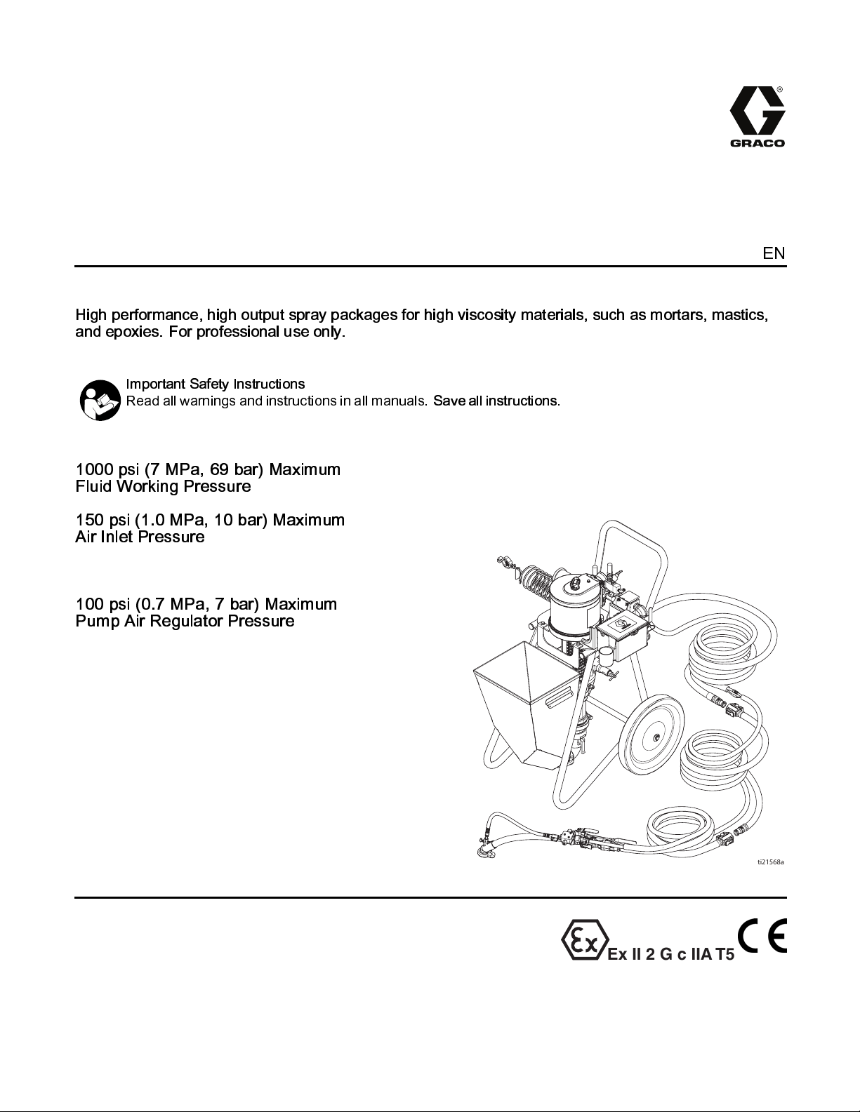
High performance, high output spray packages for high viscosity materials, such as mortars, mastics,
and epoxies. For professional use only.
Important Safety Instructions
Read all warnings and instructions in all manuals.
1000 psi (7 MPa, 69 bar) Maximum
Fluid Working Pressure
150 psi (1.0 MPa, 10 bar) Maximum
Air Inlet Pressure
100 psi (0.7 MPa, 7 bar) Maximum
Pump Air Regulator Pressure
Save all instructions.
332612A
EN
Ex II 2 G c IIA T5
ti21568a
Page 2

Contents
Related Manuals ................................................ 2
Warnings ........................................................... 3
Models............................................................... 6
Component Identification..................................... 7
Overview ..................................................... 7
Details......................................................... 8
Mortar Spray Applicator................................ 9
HTX 680 (Internal Air) Applicator...................10
System Components.................................... 11
Grounding .......................................................... 12
Setup................................................................. 13
Pressure Relief Procedure .................................. 14
Wet Out the System............................................ 15
Mix the Material.................................................. 18
Prime with Mortar or Epoxy ................................. 19
Spray................................................................. 21
Prevent Packout .......................................... 21
Before S tarti ng or Stopping Material
Flow .............................................. 21
Spraying...................................................... 21
Spray Adjustments (Mortar Spray
Applicator) ............................................ 23
Air Flow Valve Adjustment............................ 23
Material Flow Adjustments............................ 23
Spray Techniques........................................ 24
Installing Nozzle Retaining Cap..................... 24
Material Compatibility................................... 24
Spray Adjustments (HTX 680 Applicator) ............. 25
Flush ................................................................. 26
Notes................................................................. 29
Disassemble and Clean the Pump (Daily).............30
Shutdown...........................................................33
Maintenance ...................................................... 34
Daily Maintenance ....................................... 34
Troubleshooting.................................................. 35
Repair................................................................ 37
Replace Pump Components......................... 37
Replace Air Motor........................................37
Replace Pump Lower ................................... 37
Parts.................................................................. 38
Accessories........................................................44
Technical Specifications...................................... 45
Graco Standard Warranty....................................48
Related Manuals
Manuals are available at www.graco.com.
Component manuals in Engli sh:
Manual Description
332651
332767
332768
312796 NXT Air Motors Instructions - Parts
332649 Pump Lower Instructions - Parts
332650 Pump Instructions - Parts
Mortar Spraying Tips
Mortar Spray Applicators Op erati on -
Parts
HTX 680 Applicator Operation - Parts
2
332612A
Page 3

Warnings
Warnings
The following warnings are f or the setup, use, grounding, maintenance, and repair of this equipment. The
exclamation point symbol alerts you to a general warning and the hazard symbols refer to procedure-specific
risks. When these symbols appear in the body of this manual or on warning label s, refer back to these
Warnings. Product-specific hazard symbols and warnings not covered in this section may appear throughout
the body of this manual where applicable.
WARNING
FIRE AND EXPLOSION HAZARD
Flammable fumes, such as solvent and paint fumes, in
prevent fire and explosion:
• Use equipment only in well ventilated area.
• Eliminate all ignition sources; such as pilot lights, cigarettes, portable electric lamps, and
plastic drop cloths (potential static arc).
• Keep work area free of debris, including solvent, rags and gasoline.
• Do not plug or unplug power cords, or turn power or light switches on or off when flammable
fumes are present.
• Ground all equipment in the work area. Se e
• Use only grounded hoses.
• Hold applicator firmly to side of grounded pail when triggering into pail. Do not use pail
liners unless they are antistatic or conductive.
•
Stop operation immediately
equipment until you identify and correct the problem.
• Keep a working fire extinguisher in the work area.
SKIN INJECTION HAZARD
High-pressure fluid from dispensing device, hose leaks, or ruptured components will pierce
skin. This may look like just a cut, but it is a serious injury that can result in amputatio n.
immediate surgical treatment.
• Do not point dispensing device at anyone or at any part of the body.
• Do not put your hand over the fluid outlet.
• Do not stop or deflect leaks with your hand, body, glove, or rag.
•Followthe
checking, or servicing equipment.
• Tighten all fluid connections before operating the equipment.
• Check hoses and couplings daily. Replace worn or d amaged parts immediately.
Pressure Relief Procedure
if static sparking occurs or you feel a shock.Do not u se
Grounding
when you stop dispensing and before cleaning,
work area
instructions.
canigniteorexplode.Tohelp
Get
332612A 3
Page 4
Warnings
WARNING
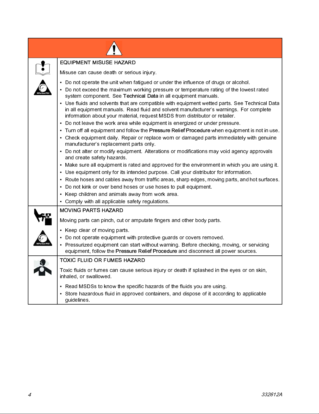
EQUIPMEN T MISUSE HAZARD
Misuse can cause death or serious injury.
• Do not operate the unit when fatigued or under the influence of drugs o r alcohol.
• Do not exceed the maximum working pressure or temperature rating of the lowest rated
system component. See
• Use fluids and solvents that are compatible with equipment wetted parts. See Technical Data
in all equipment manuals. Read fluid and solvent manufacturer’s warnings. For comple te
information about your material, request MSDS from distributor or retailer.
• Do not leave the work area while equipment is energized or under pressure.
• Turn off all equipment and follow the
• Check equipment daily. Repair or replace worn or damaged parts immediately with genuine
manufacturer’s replacement parts only.
• Do not alter or modify equipment. Alterations or modifications may void agency approvals
and create safety hazards.
• Make sure all equipment is rated and approved for the environment in which you are using it.
• Use equipment only for its intended purpose. Call your distributor for information.
• Route hoses and cables away from traffic areas, sharp edges, moving parts, and hot surfaces.
• Do not kink or over bend hoses or use hoses to pull equipment.
• Keep children and animals away from work area.
• Comply with all applicable safety regulations.
Technical Data
Pressure Relief Procedure
in all equipment manuals.
when equipment is not in use.
MOVING PARTS HAZARD
Moving parts can pinch, cut or amputate fingers and other body parts.
• Keep clear of moving parts.
• Do not operate equipment with protective guards or covers removed.
• Pressurized equipment can start without warning. Before checking, moving, or servicing
equipment, follow the
TOXIC FLUID OR FUMES HAZARD
Toxic fluids or fumes can cause serious injury or death if splashed i n the eyes or on skin,
inhaled, or swallowed.
• Read MSDSs to know the specific hazards of the fluids you are using.
• Store hazardous fluid in approved containers, and dispose of it according to applicable
guidelines.
Pressure Relief Procedure
and disconnect all power sources.
4
332612A
Page 5
PERSONAL PROTECTIVE EQUIPMENT
Wear appropriate protective equipment when in the work area to help prevent serious injury,
including eye injury, hearing loss, inhalation of toxic fumes, and burns. This protective
equipment includes but is not limited to:
• Protective eyewear, and hearing protection.
• Respirators, protective clothing, and gloves as recommended by the fluid and solvent
manufacturer.
SUCTION HAZARD
Powerful suction could cause serious injury.
• Never place hands near the pump fluid inlet when pump is operating or pressurized.
Material Self-ignition
Warnings
WARNING
Some materials may become self-igniting if applied
too thick. Read material manufacturer’s warnings and
material MSDS.
Changing Materials
NOTICE
Changing the material types used in your equipment
requires special attention to avoid equipment damage
and downtime.
• When changing materials, flush the equipment
multiple times to ensure it is thoroughly clean.
• Always clean the fluid inlet strainers after flushing.
• Check with your material manufacturer for chemical
compatibility.
• When changing between epoxies and urethanes
or polyureas, disassemble and clean all fluid
components and change hoses.
332612A 5
Page 6

Models
Models
Includes9:
Model
262927 262909 262926 24T834 24T835 24T836 24T837
Pump installed on Cart
24T837
Basic Spare Parts Kit
1
2
(included in tool box)
Feed Hopper 24T853
3
Standard 35 ft (1.7 m)
Hose Bundle 24T852
Flex Applicator 24T947
4
5
HTX 680 Manifold
Applicator 24U209
Additional Spare Parts
6
7
Additional 25 ft (7.6 m)
Hose Kit 24R254
1
Includes air motor, stainless steel pump lower, zero cavity relief valve, 1 in. male camlock outlet, air controls,
8
✔✔✔✔✔✔✔
✔✔✔✔✔✔✔
✔✔ ✔ ✔
✔✔✔✔✔
✔✔✔
✔✔✔
✔
✔
andthetwowheelcart.
2
Includes gaskets for cam and groove fittings, complete pump repair soft seal kit, and pilot tube repair fittings.
3
Includes 10 gallon (38 liter) stainless steel hopper, hopper mounting, straight and 90 degree 2 inch female
cam lock outlet.
4
Fluid hose portion of kit includes 1 in. x 25 ft fluid hose, 3/4 x 10 ft fluid whip hose, stainless steel shut off ball
valve, and fluid cam lock ends. Air line portion of kit includes 38 ft air line with pump pilot line, air line quick
disconnects, and mesh wrap. Includes 6 mil polyurethane bag tubes for fluid lines and air l ines.
5
Flex applicator includes 23 in. (58 cm) flexible hose with cam lo ck fluid inlet, angled spray head, spray air
volume control, spray air shut off valve, and motor pilot signal control valve, adjustable position center air
injection tube, rubber tip retainer, and include 3 tip sizes. Fl ex applicator is for use in low pressure spraying of
materials that pack out easily and that will be finish-trowe led.
6
HTX 680 includes cam lock fluid inlet, angled aluminum spray head, spray air volume control, spray air shut
off valve, and motor pilot signal control valve. HTX 680 uses venturi-type air injection fluid nozzles and
aluminum screw on tip retainer. Includes four nozzle sizes, a Fine Finish adapter, and f our Fine Finish tips.
HTX 680 is for use in medium pressure spray of materials that do not pack out easily.
7
Additional spare parts option includes flex applicator and pole applicator parts (rubber retainer, 3/16, 4/16,
8/16, 9/16 in. tips, and air tube o-ring), HTX applicator parts (nozzle retainer and 4 mm, 6 mm, 8 mm, 10 mm
nozzles and 1/8, 1/4, 3/8, 5/16 in. Fine Finish discs, air check valve, and spool o-rings), and pump rebuild kit.
8
Extends total length to 60 ft (18.3 m). Includes 25 ft x 1 in. fluid hose with cam lock fluid fittings, and 25 ft air
hose assembly with hose quick disconne cts and pilot tube.
9
See Parts, page 38, for details reg arding what is included with each model.
6 332612A
Page 7

Component Identification
Overview
Component Identification
AA
AC
AB
AD
AJ
AF
AK
AE
Figure 1
Key:
AA Material Hopper
AB Air Motor
AC
AD
AE Applicator
AF Material Hose (connects pump to whip
332612A
Lower
Cart
hose)
AK
AGAHAI
AG Material Whip Hose
AH
AI
AJ
AK
Air Supply to Applicator (for Air Assist and
Air Motor ON/OFF Pilot Valve), shown
disconnected
Return Air to Air Motor ON/OFF Pilot Valve
System Air Inlet
Optional hose extension
ti21568a
7
Page 8

Component Identification
Details
D
B
Y
A
F
N
C
J
E
HX
L
K
U
M
P
R
G
W
U
M
G
K
G
W
S
T
S
T
U
T
M
Detailed View
Figure 2
Key:
A
B
Air Inlet, 3/4 npt(f) Claw (Chicago) Fittings
Bleed Type Master Air Valve (required)
C Air Pressure Relief Valve
D
E
FMot
Air Filter (40 micron)
Motor Air Pressure Gauge
or Air Pressure Regulator Adjustment
b
Kno
G Pilot Ball Valve (starts/stops Air Motor)
H Motor Air Pilot Valve
J
KA
L
Zero Cavity Relief Valve
ir Assist Tube
Grounding Wire, required (see
Grounding, page 12)
M
N
V
Needle Valve for Air Assist Flow Control
Air Supply Quick Disconnect to Appl icato r
W
ti21569a
Air Inlet Quick Disconnect (W)
P
R
Fluid Outlet, 1 in. Male Camlock Fitting
Packing Nut/Wet Cup under Spring Guard
S Air Assist Nozzle Position Adjustment
Screw
T Applicator Tip Assembly
U
V
Air Assist Shutoff Ball V al ve
Applicator Material Supply Ball Valve
W Applicator Air Inlet Quick Disconnect
X
Pilot Valve Signal from App li cator Pil ot
Valve (G)
Y
Whip Check Hose Safety Cable
8 332612A
Page 9
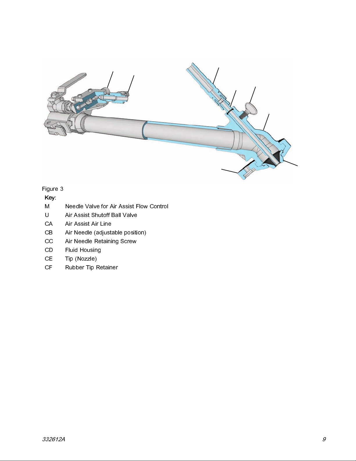
Mortar Spray Applicator
Component Identification
M
Figure 3
Key:
M
U
CA
CB Air Needle (adjustable position)
CC Air Needle Retaining Screw
CD
CE Tip (Nozzle)
CF
Needle Valve for Air Assist Flow Control
Air Assist Shutoff Ball Valve
Air Assist Air Line
Fluid Housing
Rubber Tip Retainer
U
CF
CA
CB
CC
CD
CE
332612A 9
Page 10

Component Identification
HTX 680 (Internal Air) Applicator
DG
Figure 4
Key:
M Needle Valve for Air Assist Flow Control
U Air Assist Shutoff Ball Valve
DA Air Assist Air Line
DB Fluid and Air Manifold
DC Tip (Nozzle)
DD Tip Retainer
DE Air Check Valve
DF Fluid Inlet Swivel
DG Handle
M
DF
DA
DE
U
DB
DD
DC
10 332612A
Page 11
System Components
Component Identification
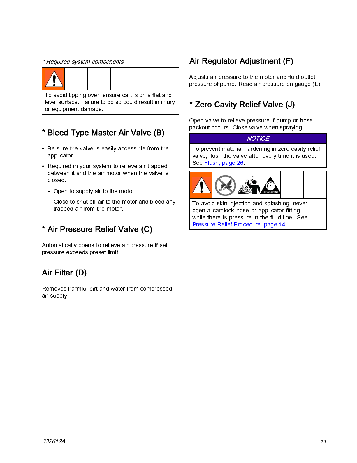
* Required system components.
To avoid tipping over, ensure cart is on a flat and
level surface. Failure to do so could result in injury
or equipment damage.
* Bleed Type Master Air Valve (B)
• Be sure the valve is easily accessible from the
applicator.
• Required in your system to relieve air trapped
between it and the air motor when the valve is
closed.
– Open to supply air to the motor.
– Close to shut off air to the motor and bleed any
trapped air from the motor.
* Air Pressure Relief Valve (C)
Air Regulator Adjustment (F)
Adjusts air pressure to the motor and fluid outlet
pressure of pump. Read air pressure on gauge (E).
* Zero Cavity Relief Valve (J)
Open valve to relieve pressure if pump or hose
packout occurs. Close valve when spraying.
NOTICE
To prevent material hardening in zero cavity relief
valve, flush the valve after every time it is used.
See Flush, page 26.
To avoid skin injection and splashing, never
open a camlock hose or applicator fitting
whilethereispressureinthefluidline. See
Pressure Relief Procedure, page 14.
Automatically opens to relieve air pressure if set
pressure exceeds preset limit.
Air Filter (D)
Removes harmful dirt and water from compressed
air supply.
332612A
11
Page 12
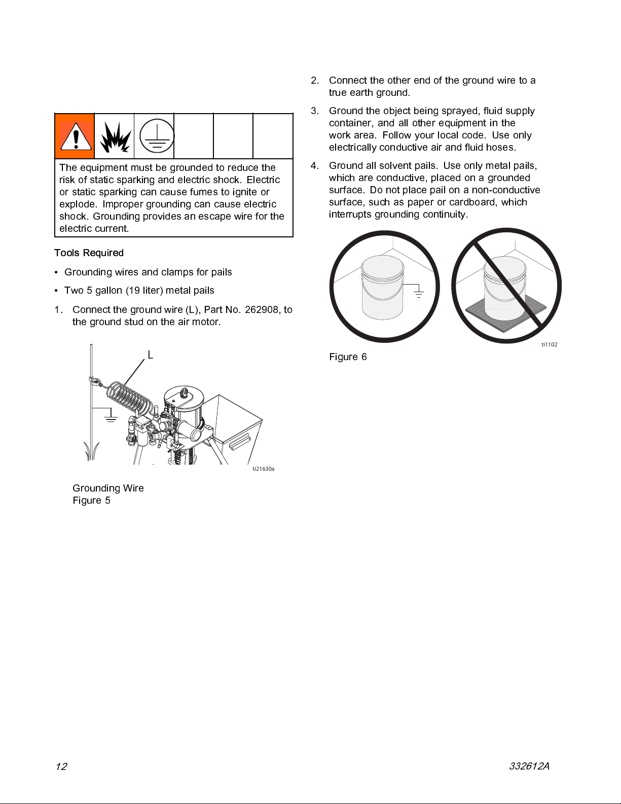
Grounding
Grounding
The equipmen
risk of stati
or static sp
explode. Im
shock. Grou
electric cu
Tools Requ
• Grounding wires and clamps for pails
• Two 5 gallon (19 liter) metal pai ls
1. Connect the ground wire (L), Part No. 262908, to
the ground stud on the air motor.
t must be grounded to reduce the
c sparking and electric shock. Electric
arking can cause fumes to ignite or
proper grounding can cause electric
nding provides an escape wire for the
rrent.
ired
L
2. Connect the other end of the ground wire to a
true earth ground.
3. Ground the object being sprayed, fluid supply
container, and all other equipment in the
work area. Follow your local code. Use only
electrically conductive air and fluid hoses.
4. Ground all solvent pails. Use only metal pails,
which are conductive, placed on a grounded
surface. Do not place pail on a non-conductive
surface, such as paper or cardboard, which
interrupts grounding continuity.
ti1102
Figure 6
Grounding Wire
Figure 5
ti21630a
12
332612A
Page 13
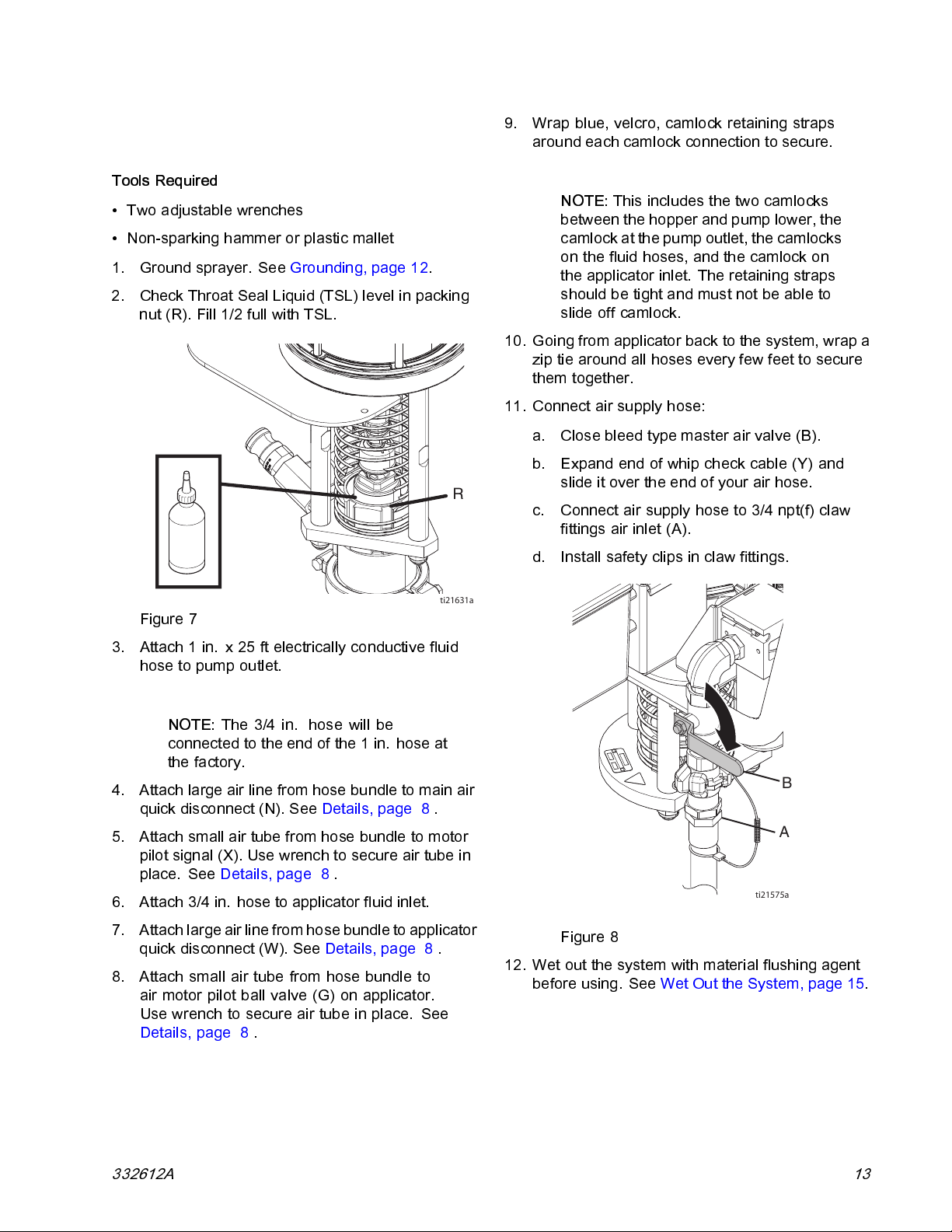
Setup
Setup
Tools Required
• Two adjustable wrenches
• Non-sparking hammer or plastic mallet
1. Ground sprayer. See Grounding, page 12.
2. Check Throat Seal Liquid (TSL) level in packing
nut (R). Fill 1/2 full with TSL.
R
9. Wrap blue, velcro, camlock retaining straps
around each camlock connection to secure.
NOTE:
between the hopper and pump lower, the
camlockat the pump outlet, the camlocks
on the fluid hoses, and the camlock on
the applicator inlet. The retaining straps
should be tight and must not be able to
slide off camlock.
10. Going from applicator back to the system, wrap a
zip tie around all hoses every few feet to secure
them together.
11. Connect air supply hose:
a. Close bleed type master air valve (B).
b. Expand end of whip check cable (Y) and
slide it over the end of your air hose.
c. Connect air supply hose to 3/4 npt(f) claw
fittings air inlet (A).
d. Install safety clips in claw fittings.
This includes the two camlocks
ti21631a
Figure 7
3. Attach1in.x25ftelectricallyconductivefluid
hose to pump outlet.
NOTE:
connected to the end of the 1 in. hose at
the factory.
4. Attach large air line from hose bundle to main air
quick disconnect (N). See Details, page 8 .
5. Attach small air tube from hose bundle to motor
pilot signal (X). Use wrench to secure air tube in
place. See Details, page 8 .
6. Attach 3/4 in. hose to applicator fluid inlet.
7. Attach large air line from hose bundle to applicator
quick disconnect (W ). See Details, page 8 .
8. Attach small air tube from hose bundle to
air motor pilot ball valve (G) on applicator.
Use wrench to secure air tube in place. See
Details, page 8 .
The 3/4 in. hose will be
B
A
ti21575a
Figure 8
12. Wet out the system with material flushing agent
before using. See Wet Out the System, page 15.
332612A 13
Page 14

Pressure Relief Procedure
Pressure Relief Procedure
Follow the Pressure Relief Procedure
whenever you see this symbol.
This equipm
is manually
injury from
splashing fl
Pressure R
and before
equipment
1. Flush the
2. Close inc
ent stays pressurized until pressure
relieved. To help prevent serious
pressurized fluid, such as skin injection,
uid and moving parts, fol low the
elief Procedure when you stop spraying
cleaning, checking, or servicing the
.
system. See Flush, page 26.
oming air ball valve (B).
B
A
ti21632a
Figure 10
To avoid injection and splashing, never open a
camlock hose or applicator fitting whi le there is
pressureinthefluidline.
5. If you suspect the applicator tip or hose is
completely clogged, or that pressure has not
been fully relieved after following the previous
steps, slowly open the zero cavity relief valve (J)
at the pump outlet. See Details, page 8 .
6. If there is still pressure trapped down the line,
very slowly loosen the threaded swivel fitting at
the pump outlet while keeping it covered until the
pressure is relieved.
ti21575a
Figure 9
3. Set air regulator (F) to zero pressure.
4. Hold applicator firmly against a grounded metal
pail. Open the material ball valve (V) on the base
of the applicator.
14
7. Flu s h the zero cavi t y relief va l v e (J). See
Flush, page 26.
NOTICE
To prevent material hardening in zero cavity relief
valve, flush the valve after every use.
332612A
Page 15

Wet Out the System
NOTICE
To prevent
mortar or e
or epoxy in
to stick t
damage an
material curing in system, never load
poxy into a dry system. Loading mortar
to a dry system will cause the material
o internal components and cure causing
d requiring replacement of those parts.
Wet Out the System
3. Partially fill the clean hopper with material
flushing agent, depending on the material you
will be spraying.
4. Turn air regulator adjustment knob (F)
counterclockwise until it stops and gauge (E)
reads zero.
E
Always w
fluid thr
before l
done wit
or comm
fluids a
spraye
et out the system by circulating clean
ough the applicator back into the hopper
oading any mixed mortar. This is normally
h the flushing fluid, but som etimes resin
ercially available concrete pump priming
re used depending on what material is being
d.
• Use the material flushing agent recommended on
the material application data sheet.
• When finished, pump out the excess fluid. Then
drain out remaining fluid by loosening the bottom
cam fitting.
1. Close the bleed type master air valve (B).
F
ti21571a
Figure 12
5. Verify zero cavity relief valve (J) is closed.
6. Place applicator outlet in grounded pail.
7. Open the fluid ball valve (V) on the applicator.
B
A
ti21575a
ti21663a
Figure 11
Figure 13
2. Remove tip from applicator.
332612A 15
Page 16

Wet Out the System
8. Open the motor on/off pil ot ball valve (G) located
on base of applicator.
ti21578a
Figure 14
9. Open bleed type master air valve (B).
10. Rotate the air regulator adjustment knob (F)
clockwise until pump begins to move slowly.
F
ti21570a
Figure 16
NOTICE
To prevent damage to pump seals caused by
cavitation, run the pump slowly until the system
is primed.
B
Figure 15
11. Continue running the pump until all of the flushing
fluid is dispensed into the pail. The system is
now wetted out.
ti21574a
ti21632a
Figure 17
16 332612A
Page 17

Wet Out the System
12. To stop dispensing, close the air motor on/off
pilot ball valve (G) and the main bleed type
master air valve (B).
B
A
ti21575a
Figure 18
13. If needed, drain remaini ng fluid from system.
NOTE:
Materials that separate more easily may
require draining the remaining fluid from the
system. Check material data sheet to determine
whether it is necessary to drain the remaining
fluid from the system.
a. Place grounded metal drain pan beneath
pump lower inlet fittings.
b. Remove hopper and fittings between hopper
and pump lower.
c. Useascrewdrivertoliftthepumplowerinlet
ball. This will drai n the remaining material
from the pump lower. When the pump stops
draining, release the pump lower inlet ball.
d. Install fittings and hopper.
e. Install camlock retaining straps.
f. Startingatthepump,raisethehosebundle
above your head and slowly move towards
the applicator. As you move towards the
applicator, the remaining fluid in the hose will
drain from the applicator into the b ucket.
332612A
17
Page 18

Mix the Material
Mix the Material
Always wet out the pump, hose, and applicator
before loading the mortar o r epoxy material. See
Wet Out the System, page 15.
Always follow the material manufacturer’s instructions
for the material being sprayed. Mortar must be
thoroughly mixed to a smooth consistency before
loading it in the hopper.
• Always add the powder slowly to the fluid while
mixing. Do not add fluid to the powder.
• In non-explosive environments only: Use a
powerful mixer drive such as a minimum 800
watt, 1/2 in. drive, electric drill. Gear reduced
drills work best. Drill should have high torque at
300-1200 rpm.
• A heavy-duty drywall mud “H” blade or large “Jiffy”
blade generally works wel l for mixing.
NOTE:
material to fill the pump and hoses.
It will take most of the first batch of
Managing Mortar After Mixing:
• Paycloseattentiontotheworklifeofthematerial
being used.
• Only mix the mortar kits as needed. Do not let
mixed mortar sit longer than necessary.
• Scrape mortar down the sides of the hopper as
the hopper material level lowers. Do not let older
mortar cure on the walls.
• Occasionally, do not refill the hopper until it is
almost empty. This ensures all material in hopper
is used while fresh.
18 332612A
Page 19

Prime with Mortar or Epoxy
NOTICE
To prevent ma
mortar into a
a dry system w
internal com
and requiri
terial curing in system, never load
dry system. Loading mortar into
ill cause the mortar to stick to
ponents and cure causing damage
ng replacement of those parts.
Prime with Mortar or Epoxy
4. Remove tip from applicator.
5. Fill the clean hopper with at least 4 gallons of the
material to be sprayed. If using 60 ft of material
hose, then fill with 6 gallons.
6. Turn air regulator adjustment knob (F)
counterclockwise until it stops and gauge (E)
reads zero.
E
The applica
priming. Al
fluid into a w
Always cir
for a few mi
1. Wet out the system. See
Wet Out the System, page 15.
2. Mix the Material. See Mix the Material, page 18.
3. Close the bleed type master air valve (B).
tor nozzle or tip must be removed during
ways push out any remaining “wet out”
aste container before circulating mortar.
culate clean mortar back into the hopper
nutes before beginning to spray.
B
F
ti21571a
Figure 20
7. Open the fluid ball valve (V) on the end of the
fluid hose.
8. Place applicator outlet in a grounded metal 5
gallon waste container.
9. Open the motor ON/OFF pilot ball valve (G)
located on base of applicator.
A
ti21575a
Figure 19
332612A 19
Page 20

PrimewithMortarorEpoxy
10. Open bleed type master air valve (B).
B
ti21574a
Figure 21
NOTICE
To prevent damage to pump seals caused by
cavitation, run the pump slowly until the system
is primed.
12. Continue running the pump until a steady stream
of material comes from the applicator.
ti21632a
Figure 23
13. To stop dispensing, close the motor ON/OFF
pilot ball valve (G). Do not close the fluid ball
valve(V)whentheairmotorisrunning.
11. Rotate the air regulator adjustment knob (F)
clockwise until pump begins to move slow ly.
F
ti21570a
Figure 22
ti21579a
Figure 24
14. Place the applicator outlet into the hopper.
15. With the fluid ball valve (V) open, o pen the motor
ON/OFF pilot ball valve (G). Material will begin
dispensing.
16. Recirculate a few gallons of material to be sure
the material is flowing properly.
17. Install a tip onto applicator. The system is now
primed and ready to spray.
20 332612A
Page 21

Spray
Spray
NOTICE
Do not operate the pump motor with the applicator
material ball valve (V) closed. This may cause the
pumporhosetopackout.
Prevent Packout
To avoid “packing out” the pump or hose:
• Use the lowest pressure and largest nozzle size
that provides an acceptable spray pattern. Thi s will
also result in seals and wear parts lasting much
longer.
• Do not use any more fluid hose than is necessary.
• Use an applicator with a rubber tip retainer that will
blow off if it plugs.
Before Starting or Stopping Material
Flow
• Never dead end the pump against the fluid shut-off
ball valve.
• Start and stop the fluid flow with the red-ha ndl ed
brass air motor pilot valve at the applicator.
• Always have the atomizing air turned on before
and after spraying fluid.
Before Starting Material Flow
1. Always open the air assist valve (U) and adjust
air assist needle valve (M) first.
Spraying
NOTICE
Do not allow pump to run without material in the
hopper. It will quickly accelerate to a high speed
causing pump seal damage.
NOTICE
To prevent material curing in system, never load
mortar into a dry system. Loading mortar into
a dry system will cause the mortar to stick to
internal components and cure causing damage
and requiring replacement of those parts.
1. Wet Out the System, page 15.
2. Mix the Material, page 18.
3. Prime with Mortar or Epoxy, page 19.
NOTICE
Failure to flush prior to material curing in the
system will result in damage to system and
may require replacement of all system parts in
contact with the material.
4. Turn air regulator adjustment knob (F)
counterclockwise until it stops and gauge (E)
reads zero.
E
2. Open applicator material ball valve (V) second.
3. Open (turn on) the motor pilot ball valve (G) last.
Before Stopping Material Flow
1. Always close (turn off) the motor pilot ball valve
(G) first.
2. Close applicator material ball valve (V) second.
3. Turn off the air assist valve (U) last.
332612A
F
ti21571a
Figure 25
21
Page 22

Spray
5. Install tip on applicator by stretching rubber
retainer with a screwdriver or screwing on
retainer, depending on your application kit.
Figure 26
6. Open air assist valve (U) and adjust the air assist
needle valve (M). See Details, page 8 .
7. Open the material ball valve (V) on the base of
the applicator.
NOTICE
Do not operate the pump motor with the
applicator material ball valve (V) closed. This
maycausethepumporhosetopackout.
8. Open the pilot ball valve for air motor (G) located
on base of applicator. See Details, page 8 .
Material will begin dispensing.
9. Adjust air motor regulator adjustment knob (F)
until desired material flow rate is achieved. Turn
clockwise to increase pressure, counterclockwise
to decrease pressure.
E
F
ti14355a
ti21571a1
Figure 27
NOTE:
See S pray Adjustmen ts (Mortar Spray
Applicator), page 23 or Spray Adjustments (HTX
680 Applicator), page 25for details ab out all of
the adjustments that can be made to the way the
system sprays.
10. If the system is approaching its cure time or the
system will be idle for enough time for material
to begin curing in the system, Flush the system.
See Flush, page 26.
22
NOTICE
Failure to flush prior to material beginning to
cure in the system will result in damage to
system and may require replacement of all
parts in contact with the material.
11. If the flushed system will be idle for more than
90 minutes, Disassemble and Clean the Pump
(Daily). See Disassemble and Clean the Pump
(Daily), page 30.
332612A
Page 23

Spray Adjustments (Mortar Spray Applicator)
Spray Adjustments (Mortar Spray Applicator)
M
Figure 28
Key:
M
U
CA
CB Air Needle (adjustable position)
CC Air Needle Retaining Screw
CD
CE Tip (Nozzle)
CF
Needle Valve for Air Assist Flow Control
Air Assist Shutoff Ball Valve
Air Assist Air Line
Fluid Housing
Rubber Tip Retainer
U
General Adjustments
The spray pattern can be adjusted by changing:
• Tip (CE) size
• Fluid flow, use air motor regulator adjustment knob
(G)
• Air flow, use needle valve (M)
• Air needle (CB) position
Adjust Air Flow:
while adjusting the needle valve (M) for the minimum
air flow necessary for a good pattern. Air bleeds from
the applicator nozzle whenever the applicator air
assist valve (U) is open. Close the val ve to stop the
air flow, if desired. Otherwise, the air valve can stay
open during priming. Ai r must be on prior to fluid flow.
Adjust Air Needle (CB) position:
needle (CB) is slightly behind the tip (CE).
Fully open the air assist valve (U),
Ensure the air
CA
CB
CC
CD
CF
NOTE:
restrict or completely block material flow.
This can result in the retainer (CF) blowing
off. Installing the needle too far back can
raise the pressure behind the fluid enough
to blow the retainer (CF) off and can cause
dripping.
Installing needle too far forward can
CE
Air Flow Valve Adjustment
To decrease air flow, turn valve knob clockwise.
To increase air flow, turn valve knob
counterclockwise.
Check material and thin as needed to maintain the
proper consistency. The material may thicken as it
sits and could slow down application or affect the
spray pattern.
Flush and dry applicator thoroughly at the end of each
use. Tips and retainers must be cleaned by hand.
Material Flow Adjustments
For a lighter spray pattern, adjust the air needle
closer to the fluid nozzle and/or reduce the fluid flow.
For a heavier spray pattern, adjust the air needle
farther back from the fluid tip and/or increase the
fluid flow.
332612A 23
Page 24

Spray Adjustments (Mortar Spray Applicator)
NOTE:
air pressure back into fluid hose, slowing
material flow.
Withdrawing needle too far can force
Spray Techniques
1. Test the spray pattern on cardboard. Hold
the applicator 6-18 in. (150-450 mm) from the
surface. Use this spraying distance for most
applications.
2. Adjust fluid flow until material flow is a dequate.
2. Insert screwdriver through hole in tab of nozzle
retaining cap.
3. Push screwdriver head against notch on
applicator tip and pry nozzle retaining cap over
lip until it snaps into place.
3. Adjust the applicator air assist needle valve to
achieve a uniform round spray pattern.
4. Consider the size of aggregate in the material
and the coarseness of the spray pattern. Larger
nozzles allow heavier patterns.
5. Overlap each stroke 50%. A circular overlapping
pattern may give the best results, and is obtained
by grasping the flex-head and swinging the head
around as the hose flexes.
When spraying small confined areas use the valve
and knob to make fine adjustments without adjusting
the pump.
Typically desired spray pressure is 20-25 psi
(140-170 kPa, 1.4-1.7 bar) on the motor air
regulator (F). Higher pressures may cause excessive
wear on the fluid pump. Select a fluid tip l arge
enough to spray at low pressure. Some materia ls will
packout at higher pressures.
Installing Nozzle Retaining Cap
ti14355a
Figure 29
4. Turn the rubber retainer back and forth to be sure
it is fully seated.
Material Compatibility
NOTICE
To prevent the seals and rubber tip from swelling,
do not leave solvent in the applicato r when not in
use.
The nylon hose in the Flex Applicator is compatible
with solvents. The rubber gasket in the cam and
groove inlet fitting and the rubber nozzle retainer
should be hand cleaned and dried after each use.
1. Place nozzle retaining cap over top lip of
applicator housing.
24
332612A
Page 25

Spray Adjustments (HTX 680 Applicator)
Spray Adjustments (HTX 680 Applicator)
DG
M
Figure 30
Key:
M Needle Valve for Air Assist Flow Control
U Air Assist Shutoff Ball Valve
DA Air Assist Air Line
DB Fluid and Air Manifold
DC Tip (Nozzle)
DD Tip Retainer
DE Air Check Valve
DF Fluid Inlet Swivel
DG Handle
The spray pattern can be adjusted by changing:
• Tip (DC) size
• Fluid flow, use air motor regulator adjustment knob
(G)
• Air flow, use needle valve (M)
The standard applicator adjustment
the air assist valve (U), while adjusting the needle
is to fully open
DA
DE
U
DB
DD
DC
DF
valve (M) for the minimum air flow necessary for a
good pattern.
Air bleeds from the applicator nozzle
the applicator air assist needle valve (M) is open.
Close the valve (U) to stop the majority of air flow, if
desired. Some air will still bleed through valve (U) to
help keep the air passages clean. Otherwise, the air
valve(U)canstayopenduringpriming.Airmustbe
on prior to any fluid flow.
Adjusting the spray pattern
balance the fluid flow and the air to the applicator,
and requires the correct tip size.
Always run full air volume through the applicator
when you are done spraying to remove any fluid
residue. Remove and clean the tip (DC) by hand.
Removeaircheckvalve(DE)tobesurenofluidhas
backed up to the check valve. If it has, remove and
clean air spool valve (U).
Fine Finish pattern discs and adapter kit 287227 is
included and can be added for more pattern control.
See manual 310617.
requires testing to
whenever
332612A 25
Page 26

Flush
Flush
NOTICE
Failure to flush prior to material curing in the
system will result in damage to system and may
require replacement of all system parts in contact
with the material.
NOTICE
If the zero cavity pressure relief valve has been
used to relieve pressure, the valve must be flushed
to prevent material hardening in zero cavity relief
valve. If that is not sufficient, remove, disassemble,
andcleanthevalvethenreinstall.
2. Remove applicator tip and retainer.
ti21643a
Figure 32
• Flush if the materials in the system are about to
reach their cure time.
• Flush any time the flow rate starts to decrease as
this is a sign that material is starting to thicken and
cure.
• Always flush the system at least twice, draining
all material flushing agent between flushes then
replacing with clean material flushing agent.
• For some mortars, it is recommended to flush
every 3 - 5 kits. Others can run continuously
without flushing. See material manufacturer
recommendation.
1. Close the bleed type master air valve (B).
B
3. Place applicator outlet in a waste container. The
wastecontainermustbelargeenoughtohold
all dispensed material.
ti21632a
Figure 33
4. With air assist air flowing, open the material ball
valve (V) on the base of the applicator.
5. Open the pilot ball valve (G) located on base of
applicator.
A
ti21575a
gure 31
Fi
26 332612A
Page 27

Flush
6. Open bleed type master air valve (B) to begin
dispensing.
B
ti21574a
Figure 34
7. When the material level in the hopper is within a
few inches of the material inlet at the bottom:
a. Scrape th e material down the sides of the
hopper.
b. Fill the hopper with water or solvent as the
material runs out and continue dispensing.
8. Keep the hopper filled with material flushing
agent while dispensing.
10. Place applicator in the system hopper with the
outlet pointing down to enable fluid circulation.
NOTE:
If flushing with solvent, do not
submerge the applicator in the solvent.
11. Circulate clean water or solvent:
a. Fill the system hopper with clean water or
solvent.
ti21644a
Figure 36
b. Use a scrub brush to scrub the walls of the
hopper.
ti21657a
re 35
Figu
NOTE:
Be prepared to decrease the air
pressure when the material exiting the
hose changes to water or solvent. Water
and solvent pump more easily so pump
speed will increase.
9. When water or solvent begins to exit the
applicator outlet, close the pilot ball valve (G)
located on base of applicator to stop dispensing.
c. Open the pilot ball valve (G) on applicator to
begin circulating water or solvent.
d. Run the pump at 60-90 cycles per min ute
for 3-5 minutes. Adjust air pressure as
necessary to maintain 60-90 cycles per
minute.
NOTE:
High flushing fluid velocity is
the most important item for effective
cleaning. The fluid hose should
shake while the pump is running.
This is necessary to maximize the
cleaning effects of flushing.
e. While pumping at 60–90 cycles per minute,
close then open the pilot ball valve (G) many
times to clean it. Each time the pilot ball valve
(G) is closed, close then open the fluid ball
valve(V)toflushthefluidballvalve.Ensure
332612A
27
Page 28

Flush
fluid ball valve is open before opening pilot
ball valve (G).
NOTE:
gets hard to operate, it should
be disassembled, cleaned, and
re-packed with grease.
f. Decrease air pressure to air motor back to
operating pressure.
g. Close the air motor pilot ball valve (G).
h. Place applicator outlet in a grounded metal
waste container.
i. Open air motor pilot ball valve (G) to dispense
into grounded metal waste container.
j. Dispense into grounded metal waste
container until hopper is almost empty then
close air motor pilot ball valve (G).
k. Repeat this entire “Circulate clean water
or solvent” step one more time to ensure
system is thoroughly flushed.
When the fluid ball valve
12. After performing the previous step at least twice,
drain remaining flushing fluid from system:
a. Place grounded metal drain pan beneath
pump lower inlet fittings.
b. Remove hopper and fittings between hopper
and pump lower.
c. Use a screwdriver to lift the pump lower inlet
ball. This will drain the remaining material
from the pump lower. When the pump stops
draining, release the pump lower inlet ball.
d. Install fittings and hopper.
e. Install camlock retaining straps.
f. Starting at the pump, raise the ho se bundle
above your head and slowly move towards
the applicator. As you move towards the
applicator, the remaining fluid in the hose will
drain from the applicator into the bucket.
13. Disassemble and clean the pump at the end
of every day. The procedure takes about 10
minutes. See Disassemble and Clean the Pump
(Daily), page 30.
28 332612A
Page 29

Notes
Notes
332612A 29
Page 30

Disassemble and Clean the Pump (Daily)
Disassemble and Clean the Pump (Daily)
Suggested Tools
• 5/8 in. box end wrench or 5/8 in. socket and ratchet
• Rubber mallet (to break items loose, if necessary)
BM
BL
BU
BJ
BP
BK
BE
BH
BD
BT
BT
BI
BF
BG
BS
BV
BB
BC
BN
BA
BR
Figure 37
30 332612A
ti21645a
Page 31

Key
BA Inlet Elbow with Camlock
BB Inlet Housing Clamp
BC Inlet Housing Assembly
BD Inlet Ball
BE Inlet Ball Stop
BF Pump Rod Assembly
BG Outlet Ball Stop
BH Piston Seal
BI Cylinder
BJ Cylinder Clamp
BK Outlet Housing
BL Throat Packing
BM Packing Nut (non-adjustable)
BN Hopper
BP Pump Outlet
BR Hopper Release Camlock
BS Outlet Ball
BT Cylinder O-rings
BU Outlet Housing Lock Nut
BV Ball Cage Spring
Disassemble and Clean the Pump (Daily)
NOTE:
As items are disassembled, use a
soft brush and water or a compatible solvent
to clean components.
1. Flush the system. See Flush, pag e 26.Stop
pump near bottom of its stroke.
2. Perform Pressure Relief Procedure. See
Pressure Relief Procedure, page 14.
3. With fluid pressure relieved, remove material
hose from pump outlet (BP).
4. Disconnect hopper at outlet camlock (BR) then
remove hopper (BN).
5. Remove inlet elbow (BA).
6. Tip cart back so it rests on the back of the cart.
Always Keep Spare Parts Stocked
Always keep spare parts stocked to ensure getting
back up and running as quickly as possible. Parts
to keep stocked include:
• Cam and groove fitting gaskets
• Spray tips
•Tipretainer
• Rod and cylinder seals
• Cylinder o-rings
• Other parts as needed
To prevent skin inj ection and splashing, never
open a camlock hose or applicator fitting
while there is pressure in the fluid li ne. See
Pressure Relief Procedure, page 14.
See the figure at the begin ni ng of this section for part
references.
ti21655a
Figure 38
7. While holding onto the inlet housing (BC), use
a5/8in. wrenchtoloosenthetwonutson
the inlet housing clamp (BB) then remove inlet
housing (BC).
8. Remove inlet ball stop (BE) and ball cage spring
(BV).
9. Use 5/8 in. wrench (64) to loosen the two nuts on
the cylinder clamp (BJ) then remove cylinder (BI).
10. Disconnect pump rod (see the following figure):
a. Pushpistonrodprotectivespringupand
away from coupling assembly (BF1-BF3).
Disassemble and clean the pump at the end of every
day. The procedure takes about 10 minutes.
b. Remove clip (BF1), and slide coupling cover
(BF2)uptoremovecoupling(BF3).
332612A 31
Page 32

Disassemble and Clean the Pump (Daily)
9. Slide cylinder (BI) over rod (BF) with o-ring (BT)
installed between outlet housing (BK) and
cylinder (BI).
BF1
BF2
Figure 39
11. Pull rod (BF) down and out of outlet housing (BK).
12. Remove outlet ball stop (BG) from rod (BF) by
pushing o-rings off of ball stop (BG).
13. Loosen and remove packing nut (BM) then
remove throat packing (BL).
14. Useabrushandsolventtocleanallloosepieces.
NOTE:
The pump rod (BF) is not disassembled
unless the piston packing or seat needs to be
replaced.
NOTE:
The inlet housing (BC) is not
disassembled unless the inlet seat needs to be
replaced.
Assemble the Pump
1. Loosely install throat packing (BL) with the open
end facing into the pump.
BF3
NOTE:
If the o-ring (BT) does not stay in
place while assembling the cylinder (BI)
to the housing (BK), the cart may need
to be tipped upright to install properly.
ti21656a
After clamp is installed, tip cart back to
horizontal position to finish assembly.
10. Use cylinder clamp (BJ) to secure cylinder (BI)
to outlet housing (BK).
NOTE:
Each clamp has one flat so that
only one wrench is required to tighten
clamp. Align bolt head with flat then
useawrenchonthenuttotighten.
Tighten both sides of the clamp evenly to
approximately 10 ft-lb (14 N•m).
11. Install inlet ball (BD), ball cage spring (BV), and
inlet ball stop (BE) in inlet housing (BC).
12. With inlet ball (BD), ball cage spring (BV), and
inlet ball stop (BE) in place, place o-ring (BT)
between cylinder (BI) and inlet housing (BC)
then use inlet housing clamp (BB) to install inlet
housing (BC) onto cylinder (BI).
2. Install packing nut (BM) hand-tight.
3. Lubricate the ball s (BS, BD) to ensure they do
not stick.
4. Install outlet ball (BS), out let ball stop (BG) with
o-rings into rod (BF). Ensure outlet ball stop
o-rings are in the grooves on the outlet ball stop
rod.
5. Grease the packing on the rod (BF).
6. Gently slide rod (BF) through throat packing (BL).
7. Install coupling (BF3), slide coupling cover (BF2)
over coupling, then install clip (BF1) to secure
pump rod (BF) to air motor.
8. Use a flat-tip screwdriver and a plastic mallet to
tighten packing nut (BM) until it stops.
NOTE:
This is not an adjustable packing
but the packing nut (BM) does need to
be tight against the throat packing (BL).
NOTE:
Each clamp has one flat so that
only one wrench is required to tighten
clamp. Align bolt head with flat then
useawrenchonthenuttotighten.
Tighten both sides of the clamp evenly to
approximately 10 ft-lb (14 N•m).
13. Install inlet elbow (BA) onto inlet housing (BC).
14. Tip cart up.
15. Install hopper (BN) onto the hopper bracket and
connect to inlet elbow (BA).
16. Install material hose onto pump outlet (BP).
32 332612A
Page 33

17. Wrap blue, velcro, camlock retaining straps
around each camlock connection to secure.
Shutdown
NOTE:
between the hopper and pump lower, the
camlock at the pump outlet, the camlocks
on the fluid hoses, and the camlock on
the applicator inlet. The retaining straps
should be tight and must not be able to
slide off camlock.
18. Add TSL to the packing nut (BM) until 1/2 full.
This includes the two camlocks
Shutdown
NOTICE
To prevent rust, never leave water or water-based
fluid in pump overnight.
1. Flush the system. See Flush, page 26.
NOTE:
flush with water first, then with a rust inhibitor,
such as mineral spirits solvent (also called white
spirit), to prevent rust.
If you are pumping water-based fluid,
2. Perform Disassemble and Clean the Pump
(Daily) procedure. See Disassemble and Clean
the Pump (Daily), page 30.
332612A 33
Page 34

Maintenance
Maintenance
Preventative Maintenance
The operating conditions of your particular system determine how often maintenance is required. Establish
a preventive maintenance schedule by recording when and what kind of maintenance is needed, and then
determine a regular schedule for checking your system.
Daily Maintenance
1. Flush the system. See Flush, page 26.
2. Relieve pressure. See
Pressure Relief Procedure, page 14.
3. Perform the Disassemble and Clean the Pump
(Daily) procedure at the end of every day. See
Disassemble and Clean the Pump (Daily), page
30.
4. Drain water from air filter.
5. Clean hopper with a scrub pad. It is
recommended that you clean the outside of the
sprayer using a cloth and compatible solvent.
6. Check hoses, tubes, and couplings. Tighten all
fluid connections before each use.
7. Check and replace camlock gaskets as needed.
Corrosion Protection
NOTICE
To prevent rust, never leave water or water-based fluid
in pump overnight.
Always flush the pump before the fluid dries on the displacement rod. First, flush with water or a compatible
solvent, then with oil. Relieve the pressure, but leave the oil in the pump to protect the parts from corrosion.
Cart Maintenance
Periodically lubricate the axle between points A and
B with lightweight o il. See the following figure.
Keep the cart clean by wiping up spills dai ly, using a
compatible solvent.
A
B
ti21634a
Cart Assembly
Figure 40
34 332612A
Page 35

Troubleshooting
To prevent sk
open a camloc
while there
Pressure Re
1. Perform Pre
Pressure Re
2. Check all p
solutions
pump.
PROBLEM — CAUSE — SOLUTION
Example:
•
Problem.
–
Cause.
♦ S olu tio n.
in injection and splashing, never
k hose or applicator fitting
is pressure in the fluid line. See
lief Procedure, page 14.
ssure Relief Procedure. See
lief Procedure, page 14.
ossible problems, causes, and
listed below before disassembling
Troubleshooting
•
Output low on both strokes.
–
Air line restricted or air supply inadequate.
Valves closed or clogged.
♦ Clear air li n e; increase air supply. Check that
valves are open.
–
Fluid hose/applicator obstructed; hose ID too
small.
♦ Clear hose or applicator*; use hose with larger
ID.
•
Output low on down-stroke.
–
Open or worn intake valve.
♦ Clear or service intake valve.
•
Output low on up-stroke.
–
Open or worn piston valve or packings.
♦ Clear piston valve; replace packings.
•
Does not operate.
–
Air mot
♦ Remove valve by disconnecting swivel unions.
–
Valve closed or clogged.
♦ Clear air line; increase air supply. Check that
–
Fluid hose or applicator obstructed.
♦Clea
–
Drie
♦ Clean rod; always stop pump at bottom of
–
Air motor parts dirty, wo rn or damaged.
♦ Cl ean or repair air motor. S ee motor manual.
or pilot valve (211) is faul ty.
Connect hose directly to air motor. Operate
motor directly with air regulator (210).
valves are open.
nhoseorapplicator.*
d fluid on displacement rod or inlet ball.
stroke; keep wet-cup filled with compatible
solvent. Be sure inlet ball moves freely.
•
Erratic accelerated speed.
–
Fluid supply exhausted, clogged suction.
♦ Refill hopper and prime pump.
–
Open or worn piston valve or packings.
♦ Clear piston valve; replace packings.
–
Open or worn intake valve.
♦ Clear or service intake valve.
•
Cycles or fails to hold pressure at stall.
–
Worn check balls, seats, or piston packing.
♦ Service lower. See Disassemble and Clean
thePump(Daily),page30.
332612A 35
Page 36

Troubleshooting
•
Poor finish or irregular spray pattern.
–
Incorrect fluid pressure at applicator.
•
Motor powered but nothing comes out of hose.
–
Pump is packed out with dry or cured material.
♦ S ee applicator manua l; read fluid
manufacturer’s recommendations.
–
Inadequate air assist air pressure.
♦ Adjust air assist needle valve.
–
Dirty, worn, or damaged spray applicator.
♦ Servi c e spra y appl i cator. See spra y appl icator
manual.
•
Cannot open or close air motor pilot ball valve on
applicator.
–
Dirty air clogged the air motor pilot valve.
♦ If no ball valve is immediately available:
Bypass the air motor pilot valve so air is
always supplied to air motor, regardless of
applicator pilot valve position. Then control
fluid flow by adjusting air regulator pressure
up and down as needed. Install new pilot ball
valve when one becomes available.
•
Cannot open or close fluid ball valve on hose at
applicator.
–
Mortar cured in valve due to insufficient flushing.
♦ If no ball valve is immediately available:
Relieve pressure in system, remove ball valve,
then control fluid flow by adjusting air regulator
up and down as needed.
♦ Disassembly, clean, and repack ball valve with
lithium grease.
♦ Disassemble and Clean the Pump (Daily),
page 30
–
Hose is packed out with dry or cured material.
♦ Reverse hose and try to push out bad material.
♦ S om e materia ls may need only 1 in. inn er
diameter fluid line all the way to the applicator.
•
Material is too thick to push through hose without
packing out.
–
3/4in.x10ftwhiphoseistoorestrictive.
♦ Remove 3/4 in. x 10 ft whip hose from bundle
at applicator end. Move fluid ball valve to end
of 1 in. x 25 ft hose. Coil up extra air hose at
machine end.
♦ Thin and mix material thoroughly to a lower
viscosity.
♦ Use a pump system priming fluid (slime). See
Wet Out the System, page 15.
* To determine if fluid hose or applicator is obstructed,
follow Pressure Relief Procedure, page 14.
Disconnect fluid hose and place a container at pump
fluid outlet to catch any fluid. Turn on air power just
enough to start pump. If pump starts, the obstruction
is in fluid hose or applicator.
♦ Replace ball val ve.
36 332612A
Page 37

Repair
Repair
7. Tighten tie rod nuts (44).
8. Connect pump rod. S ee figure shown previously
in this section.
To prevent skin inj ection and splashing, never
open a camlock hose or applicator fitting while
there is pressure in the fluid line. Perform
Pressure Relief Procedure, page 14, before
performing any repair procedure.
Replace Pump Components
To replace any pump components
(excluding the air motor), perform the
Disassemble and Clean the Pump (Daily), page 30,
procedure.
Replace Air Motor
1. Perform Pressure Relief Procedure, page 14.
2. Note location of small air tube connections on air
motor then remove air tubes.
3. Disconnec
a. Push piston rod protective spring up and
t pump rod (see the following figure):
away from coupling assembly (BF1-BF3).
9. Connect small air tubes to ai r motor.
Replace Pump Lower
Perform this procedure to replace the entire
pump lower with a new or different pump lower.
To repair or replace any internal components
in the pump (excluding the air motor), perform
Disassemble and Clean the Pu mp (Daily), page 30.
1. Perform Pressure Relief Procedure, page 14.
2. Disconnect pump lower from hopper.
3. Disconnect material hose from pump lower outlet.
4. Disconnect pump rod (see the following figure):
a. Pushpistonrodprotectivespringupand
away from coupling assembly (BF1-BF3).
b. Remove clip (BF1), and slide coupling cover
(BF2)uptoremovecoupling(BF3).
b. Remove clip (BF1), and slide coupling cover
(BF2) up to remove coupling (BF3).
BF1
Figure 41
4. Loosen three tie rod nuts (44), then loosen
and rem ove tie rods (42) from ai r motor. See
Parts, page 38.
5. Remove air motor.
6. Align air motor with tie rods (42) then tighten tie
rods to air motor.
BF2
BF1
BF3
5. Loosen three tie rod nuts (44), then loosen
ti21656a
6. Remove pump lower.
7. Align new pump lower with tie rods (42) then
8. Tighten tie rod nuts (44).
9. Connect pump rod. S ee figure shown previously
10. Connect pump lower to hopper.
Figure 42
and rem ove tie rods (42) from ai r motor. See
Parts, page 38.
tighten tie rods to air motor.
in this section.
BF2
BF3
ti21656a
332612A 37
Page 38

Parts
Parts
M680 Systems
4
3
1
65
7
67
68
66
49
4
8
47
41
48
45
6
7
50
7
18
53
4
51
42
5
46
20
6
3
2
7
26
15
1
14
1
17
1
44
5
7
20
10
13
43
3
11,55,58
Assemble fitting (15) and zero cavity relief
valve (17) then assemble to swivel (14)
1
with relief hole pointing downward or at the
pump.
Apply pipe sealant to all non-swiveling pipe
2
threads.
Apply clear, liquid petrolatum to axles (1)
3
before assembling wheels (2).
12,55,58
Pack grease around the end of the
zero-cavity relief valve in front of the
4
threads.
Torque to 50–60 ft-lb (68–81 N∙m).
5
Torque to 145–155 ft-lb (197–210 N∙m).
6
Apply medium strength thread-locking fluid
7
to threads.
ti22048a
Quantity
f
Re
1262914CART 1111111
2 116406
3113436RING,retaining 2222222
4
38 332612A
Pa
---
rt
Description
WHEEL
MODULE, air controls; see
Air Controls
T83424T83524T83624T837
24
2222222
1111111
2909262926262927
26
Page 39

Parts
Quantity
Ref Part
6 104572 WASHER, lock spring
7■
8 155470 SWIVEL, union, 90 degree 1 1 1 1 1 1 1
10■
11■ 16V510 CAM AND GROOVE, elbow,
12■ 16V509 CAM AND GROOVE, 2 inch x
13■ 16U536 HOPPER 1 1 1 1
14 160022 UNION, adapter 1 1 1 1 1 1 1
15 127082 TEE, branch, female 1 1 1 1 1 1 1
17 16W513 VALVE, relief, zero cavity 1 1 1 1 1 1 1
18
20■
29 114958 STRAP, tie 10 10 10 10 10
30 110198 COUPLER, line, air 1 1 1 1 2
31 159841 BUSHING, 3/8 x 1/4 in. 1 1 1 1 2
32 169970 FITTING, line air 1 1 1 1 2
33 24U209 APPLICATOR, texture, pole 1 1 2
34 24T947 APPLICATOR, texture, flexible 1 1 1
41◆ M34LN0 MOTOR, air 1 1 1 1 1 1 1
42◆ 16U817 ROD, tie, 10-5/8 3 3 3 3 3 3 3
43◆ 24R253 LOWER, pump (see manual
44◆
45◆
46◆ 244819 COUPLING, assembly 1 1 1 1 1 1 1
47◆
48◆ 244820 CLIP, hairpin with lanyard 1 1 1 1 1 1 1
49◆ 262908
50◆ 111799 SCREW, cap, hex head 1 1 1 1 1 1 1
51◆ 16V671 GUARD, spring 1 1 1 1 1 1 1
53
55** 16W506 GASKET, 2 in, coupler, cam
57** 16W490 O-RING, pump cylinder
59** 16A443 NOZZLE, 3/16 inch 1
60** 16A444 NOZZLE, 1/4 inch 1
61** 16A448 NOZZLE, 1/2 inch 1
62** 16A449 NOZZLE, 9/16 inch 1
63** 16W508
64** 127265 TOOL, wrench, ratchet 1 1 1 1 1 1 1
114193 SCREW, machine, hex washer
---
---
---
101712
15H392 ROD, adapter 1 1 1 1 1 1 1
197340 COVER, coupler 1 1 1 1 1 1 1
186620
▲
Description
head
BRACKET, hopper 1 1 1 1
2inch
1-1/2 npt
PLUG, tubing, cart 2 2 2 2 2 2 2
NUT, hex, flange, serrated 8 6 8 6 8 6 8
332649)
NUT, lock
WIRE, ground, with clamp
LABEL, symbol, ground
and groove (6–pack)
(10–pack)
KIT, seals, pump
24T834 24T835 24T836 24T837 262909 262926 262927
4444444
12 10 12 10 12 10 12
1111
1111
1111111
3333333
1111111
1111111
2222
2222222
1
332612A 39
Page 40

Parts
Quantity
Ref Part
65
66
67 113505
68 107251 SCREW, machine, panhead
98 24T854 BUNDLE, hose, 35 ft 1 1 1 1 1
99 24R254 BUNDLE, hose, extension, 25
▲
*
Parts included in Pack Out Hose Clean Kit 16W601 (purchase separately).
■
◆
**
---
---
---
Replacement Danger and Warning labels, tags, and cards are available at no cost.
Parts included in Hopper Replacement Kit 24T853 (purchase separately).
Parts included in Pump 16W514 (purchase separately). See manual 332650.
Spare parts shipped with machine.
Not for sale.
Description
BRACKET,toolbox 1111111
KIT, tool box
NUT,keps,hexhead 4444444
ft
24T834 24T835 24T836 24T837 262909 262926 262927
1111111
4444444
1
40 332612A
Page 41

Air Controls
213
Parts
222
219
2
220
211
206
207
225
209
222
223
208
205
204
216
212
201
202
221
215
202
203
206
218
214
210
224
ti22050a
Apply pipe sealant to all non-swiveling pipe threads.
1
Assemble one end of lanyard between ball valve (207) and fitting (208). One end hangs loose.
2
Ref Part Description Qty
201 262658 FILTER, air, 40 micron 1
202 158491 FITTING, nipple 2
203 C20432 FITTING, cross, pipe 1
204 C20461 FITTING, nipple, reducing,
---
205
206 159239 FITTING, nipple, pipe,
207 113332 VALVE, ball, vented, 0.750 1
208 113429 COUPLING, universal,
209 113430 COUPLING, universal,
210 104267 REGULATOR, air 1
211 16W146 VALVE, 3-way, pilot
---
212
hex
FITTING, elbow, street 1
reducing
3/4–14 npt male
3/4–14 npt female
operated
BRACKET, air controls 1
Ref Part Description Qty
213 160430 GAUGE, pressure, air 1
214 155470 FITTING, swivel, union, 90
degree
215 101950 SCREW, socket head cap,
1
216 115942 NUT, hex, flange head 2
218 110198 COUPLER, line, air 1
2
219 127313 FITTING, elbow 1
220 111881
221 100737 PLUG, pipe 1
1
222 218093 HOSE, coupled 1
1
223 162505 FITTING, union, swivel 1
224 113498 VALVE, safety, 110 psi 1
225 16W586 CABLE, lanyard, whip
1
1/4x2.5inch
MUFFLER
check
1
2
1
1
---
Not for sale.
332612A
41
Page 42

Parts
Zero Cavity Relief Valve, 16W513
3
2 4
305
307
Useassemblytool15T630toinstallseal
1
(304).
Apply medium strength thread-locking fluid
2
to threads prior to installing seat (305).
Ref Part Description Qty
301 - - - HOUSING, end 1
302 16U807 STEM 1
303 15M189 SPACER, backup, seal 1
304 15M529 SEAL, check valve 1
---
Not for sale.
308
301
306
3
302
303
304
1 3
4
ti22051a
Apply lithium grease to seal, thread, and
3
o-ring.
Torque to 95–105 in-lb (10.7–11.9 N∙m).
4
Ref Part Description Qty
305 16V956 SEAT 1
306 15Y627 O-RING, PTFE 1
307 16V957 HOUSING 1
308 102915 PIN, drive 1
42
332612A
Page 43

Hose Bundles
416,456,458
432
431
432
431
452
416
424
425
416,456,458
423
428
Parts
454
430
424
430
454
425
ti22047a
427
425
Quantity
24T852 (25
ft air hose
bundle)
Ref Part
Description
24T854 (35
ft bundle)
24R254 (25
ft bundle)
24U331 (38
ft air hose
bundle)
416 289874 COUPLER KIT, 1 in. female cam/groove 2 1
421 24U184 COVER, hose, plastic, 2 in. x 50 ft 1 1
422 24U185 COVER, hose, plastic, 3 in. x 50 ft 1 1 1 1
423 16W512 HOSE, fluid, 3/4 in., coupled, 10 ft 1
424 16W511 HOSE, fluid, 1 in., coupled, 25 ft 1 1
425* 15T116 COUPLER, male, cam and groove, 1 in. 2 1
426* 158585 FITTING, nipple 1 1
427 127232 VALVE, ball, 1 inch, stainless steel,
11
1000 psi
428 24T762 HOSE, air and pilot in scuff jacket, 38 ft 1
429 114958 STRAP, tie 10 10
430 110198 COUPLER, line, air 1 1 1 1
431 159841 BUSHING, 3/8 x 1/4 in. 1 1 1 1
432 169970 FITTING, line air 1 1 1 1
452 24T829 HOSE, bundle, air, 26 ft 1 1
454
127312 FITTING, 1/4 to 1/4 tube 1 1 1 1
456 16W507 GASKET, coupler, 1 in. (6–pack) 2 2
458 240296 STRAP (4–pack) 2 2
426
*
Parts included in Pack Out Hose Clean Kit 16W601 (purchase separately).
---
Not for sale.
332612A 43
Page 44

Accessories
Accessories
Pole Applicator, 24T946
Ideal for spraying in long-reach, open areas and
low-pressure spraying of materials that packout
easily and that will be finish-troweled. The pol e
applicator is similar to the Flexible Applicator, but
with a pipe in place of the hose. See manual 332767.
Includes:
• 30 in. (76 cm) aluminum pipe with cam lock fluid
inlet
• Angled spray head
• Spray air volume control
• Spray shut-off valve
• Motor pilot signal control valve
• Adjustable position center air injection tube
• Rubber tip retaine r
• 4 different-sized tips
44
332612A
Page 45

Technical Specifications
Technical Specifications
Mortar and Epoxy Sprayer Package
U.S.
Maximum Working Pressure 1000 psi 7 MPa, 70 bar
Maximum Air Inlet Pressure 100 psi 0.7 MPa, 7 bar
Minimum Inlet Air Flow (Typical) 30 standard cubic feet per minute
Minimum Inlet Air Flow (Pump
Only)
PressureRatio(FluidtoAir)
Air Motor Piston Diameter 7.5 in. 191 mm
Stroke Length
Lower Output
Flow Rate at 30 cycles per minute 5.44 gpm 20.6 lpm
Flow Rate at 60 cycles per minute 10.88 gpm 41.2 lpm
Air In le t Size 3/4 npt(f) (Chicago Fitti ng )
Fluid Inlet Size 2 in. Cam Groove (Male)
Fluid Outlet Size 1 npt(f) with a 1 in. Cam and Groove Fitting
Weight (without fluid)
Sound Pressure 118 d B(A )*
Sound Power 118 d B(A )*
Dimensions
Height 44.5 in. 113 cm
Width 27.5 in. 70 cm
Depth (pump on cart only)
Deep (pump on cart with hopper)
Maximum Pump Speed
(Do not exceed maximum recommended pump speed of fluid pump to prevent premature pump wear)
Spraying 40 cycles per minute (typi call y less tha n 10 cycles per minute)
Flushing
Wetted Parts
Entire System Stainless steel, UHMWPE, nylon, plated steel, anodized
Pump
Hose Kits
Notes
*
Spraying simulated acoustical texture under typical conditions as specified by the material maufacturer.
8 scfm per gallon at 100 psi
4.75 in. 120 mm
41.9 cu. in. per cycle 686 cc per cycle
250 lb
(with 25 ft of 1 in. hose and
10 ft of 3/4 in. hose)
32 in. 81 cm
37 in. 94 cm
60–90 cycles per minute (only when pumping flushing fluid)
aluminum, FX-75
Stainless steel, carbide, PTFE, UHMWPE, solvent-resistant o-rings
Nylon core, plated carbon steel fittings, anodized alu-
minum, nitrile gaskets
0.85 cubic meters per minute
0.06 cubic meters per minute
10:1
(with7.6mof25mmhoseand
3.0 m of 19 mm hose)
Metric
per liter at 7 bar
113 kg
332612A 45
Page 46

Technical Specifications
M680 Performance Chart
(with 30–weight oil)
Pump Cycles Per Minute
10020 504030
1000
D
800
Pump
Outlet Flui d
Pressure in
psi
600
C
B
400
A
200
0
012345678910
Ref
A Fluid Pressu re at 20 psi Air
B Fluid Pressu re at 40 psi Air
C Fluid P
Description
ressureat70psiAir
E
Flow Rate in Gallons Per Minute
H
60
50
G
Air Flow in
40
Standard
Cubic Feet
30
F
Per Minute
20
10
0
D Fluid Pressure at 100 psi Air
E
F
G Air Consumption at 70 psi Air
H Air Consumption at 100 psi Air
Air Consumption at 20 psi Air
Air Consumption at 40 psi Air
46 332612A
Page 47

Standard
Cubic Feet
Per Minute
of Air (Cubic
Meters Per
Hour)
Technical Specifications
M680 Applicator Air Consumption
(100 psi feed to the machine)
30
20
10
0
1.0 2.0 3.0 4.0 5.0
Needle Valve Turns Open from Closed
332612A
47
Page 48

Graco Standard Warranty
Graco warrants all equipment referenced in this document which is manufactured by Graco and bearing its
name to be free from defects in material and workmanship on the date of sale to the original purchaser for use.
With the exc
twelve months from the date of sale, repair or replace any part of the equipment determined by Graco to be
defective. This warranty applies only when the equipment is installed, operated and maintained in accordance
with Graco’s written recommendations.
This warranty does not cover, and Graco shall not be liable for general wear and tear, or any malfunction,
damage or wear caused by faulty installation, misapplication, abrasion, corrosion, inadequate or improper
maintenance, negligence, accident, tampering, or substitution of non-Graco component parts. Nor shall Graco
be liable for malfunction, damage or wear caused by the incompatibility of Graco equipment with structures,
accessories, equipment or materials not supplied by Graco, or the improper design, manufacture, installation,
operation or maintenance of structures, accessories, equipment or materials not supplied by Graco.
This warranty is conditioned upon the prepaid return of the equipment claimed to be defective to an authorized
Graco distributor for verification of the claimed defect. If the claimed defect is verified, Graco will repair or replace
free of charge any defective parts. The equipment will be returned to the original purchaser transportation
prepaid. If inspection of the equipment does not disclose any defect in material or workmanship, repairs will be
made at a reasonable charge, which charges may include the costs of parts, labor, and transportation.
THIS WARRANTY IS EXCLUSIVE, AND IS IN LIEU OF ANY OTHER WARRANTIES, EXPRESS OR IMPLIED,
INCLUDING BUT NOT LIMITED TO WARRANTY OF MERCHANTABILITY OR WARRANTY OF FITNESS
FOR A PARTICULAR PURPOSE.
Graco’s sole obligation and buyer’s sole remedy for any breach of warranty shall be as set forth above. The
buyer agrees that no other remedy (including, but not limited to, incidental or consequential damages for lost
profits, lost sales, injury to person or property, or any other incidental or consequential loss) shall be available.
Any action for breach of warranty must be brought within two (2) years of the date of sale.
GRACO MAKES NO WARRANTY, AND DISCLAIMS ALL IMPLIED WARRANTIES OF MERCHANTABILITY
AND FITNESS FOR A PARTICULAR PURPOSE, IN CONNECTION WITH ACCESSORIES, EQUIPMENT,
MATERIALS OR COMPONENTS SOLD BUT NOT MANUFACTURED BY GRACO.
manufactured by Graco (such as electric motors, switches, hose, etc.), are subject to the warranty, if any, of
their manufacturer. Graco will provide purchaser with reasonable assistance in making any claim for breach of
these warranties.
In no event will Graco be liable for indirect, incidental, special or consequential damages resulting from Graco
supplying equipment hereunder, or the furnishing, performance, or use of any products or other goods sold
hereto, whether due to a breach of contract, breach of warranty, the negligence of Graco, or otherwise.
FOR GRACO CANADA CUSTOMERS
The Parties acknowledge that they have required that the present document, as well as all documents, notices
and legal proceedings entered into, given or instituted pursuant hereto or relating directly or indirectly hereto, be
drawn up in English. Les parties reconnaissent avoir convenu que la rédaction du présente document sera en
Anglais, ainsi que tous documents, avis et procédures judiciaires exécutés, donnés ou intentés, à la suite de ou
en rapport, directement ou indirectement, avec les procédures concernées.
eption of any special, extended, or limited warranty published by Graco, Graco will, for a period of
These items sold, but not
Graco Information
For the latest information about Graco products, visit www.graco.com.
To place an order,
Phone:
612-623-6921
All written and visual data contained in this document reflects the latest product information available at the time of publication.
GRACO INC. AND SUBSIDIARIES • P.O. BOX 1441 • MINNEAPOLIS MN 55440-1441 • USA
contact your Graco Distributor or call to identify the nearest distributor.
or Toll Free:
Graco reserves the right to make changes at any time without notice.
Original Instructions. This manual contains English. MM 332612
Copyright 2013, Graco Inc. All Graco manufacturing locations are registered to ISO 9001.
1-800-328-0211
For patent information, see www.graco.com/patents.
Graco Headquarters:
International Offices:
Fax:
612-378-3505
Minneapolis
Belgium, China, Japan, Korea
www.graco.com
 Loading...