

Page 1

Operation
ProMix® PD2K Pr
Automatic Spr
Electronic positive displacement proportioner for fast-setting two-component materials. Automatic
system with Advanced Display Module. For professional use only.
Important Safety Instructions
Read all warnings and instructions in this manual and in your
installation, repair, and associated component manuals.
Save these instructions.
See page 3
approvals information.
for model part numbers and
ay Applications
oportioner for
332564B
EN
PROVEN QUALITY. LEADING TECHNOLOGY.
Page 2

Contents
Related Manuals ..................................................3
Models................................................................. 4
Warnings ............................................................. 6
Important Isocyanate (ISO) Information.................. 9
General Information ............................................ 10
Advanced Di
ADM Display
USB Downloa
USB Upload P
ADM Keys an
Soft Key Ic
Navigatin
Screen Ico
Pre-Operation Tasks........................................... 17
Pre-operation Checklist ................................ 17
Power On .................................................... 17
Initial System Setup ..................................... 18
Flush Before Using Equipment...................... 18
Valve Settings.............................................. 18
Pressure Relief Procedure .................................. 19
Without Color Change.................................. 19
With Color Change....................................... 19
Operat
Prime a
Sprayi
Purgin
Shutd
Operation Using a Programmable Logic
Network Communications and Discrete
Discrete I/O ................................................. 24
Communication Gateway Module (CGM)
Network Communication I/O Data Map........... 28
Operation Flow Charts ................................. 42
Network Communication - Dynamic
Flow Control System .................................... 57
Run Mode Screens............................................. 58
Opening Screen........................................... 58
splay Module (ADM) ........................ 11
................................................ 11
d Procedure............................ 11
rocedure ................................ 12
d Indicators ............................. 13
ons ............................................. 14
g the Screens ................................ 16
ns ............................................... 16
ion Using Automatic Display Module
(ADM)................................................... 2
nd Fill the System............................. 20
ng...................................................... 21
g ....................................................... 22
own.................................................... 23
Controller (PLC) .................................... 24
I/O................................................. 24
Details ........................................... 27
Command Structure (DCS) ............. 47
Home Screen .............................................. 58
Spray Screen............................................... 62
Fill Screen................................................... 63
Usage Screen.............................................. 64
Jobs Screen ................................................ 65
Errors Screen .............................................. 65
Events Screen ............................................. 65
Setup Mode Screens .......................................... 66
Password Screen......................................... 66
System Screen 1 ......................................... 67
System Screen 2 ......................................... 68
System Screen 3 ......................................... 69
System Screen 4 ......................................... 70
System Screen 5 ......................................... 71
Recipe Screen............................................. 72
Flush Screen ............................................... 73
Pump Screen 1 ............................................ 74
Pump Screen 2 ............................................ 75
Pump Screen 3 ............................................ 76
Pressure Alarm and Deviation Limits............. 76
Calibration Screens...................................... 77
Maintenance Screens................................... 80
Advanced Screen 1...................................... 82
Advanced Screen 2...................................... 83
Advanced Screen 3...................................... 83
0
ation Checks.............................................. 84
Calibr
Pump Pr
Pump Vo
Solven
Color Change.....................................................87
Single Color Systems ................................... 87
Multiple Color Systems................................. 87
System Errors ....................................................88
To Clear Error and Restart............................88
Gun Trigger Input Function ........................... 88
Error Codes................................................. 89
tenance .................................................... 102
Main
Prev
Flu
Cle
Technical Data ................................................. 103
Graco Standard Warranty.................................. 104
essure Check ................................. 84
lume Check.................................... 85
t Meter Calibration ............................. 86
entive Maintenance Schedule .............. 102
shing .................................................... 102
aning the ADM...................................... 102
2
332564B
Page 3

Related Manuals
Related Manuals
Current manua
Manual No. Description
332709
332458
332339 Dosing Pumps, Instructions/Parts
332454
ls are available at www.graco.com.
ProMix PD2K Proportioner for
Automatic Spray Applications,
Repair-Parts
ProMix PD2K Proportioner for
Automatic Spray Applications,
Installation
Color/Catalyst Dispense Valves,
Instructions/Parts
Manual No. Description
332455
333282
332456 Pump Expansion Kits,
Color Change Kits, InstructionsParts
Color Change and Remote Mix
Manifold Kits, Instructions-Parts
Instructions-Parts
332564B 3
Page 4
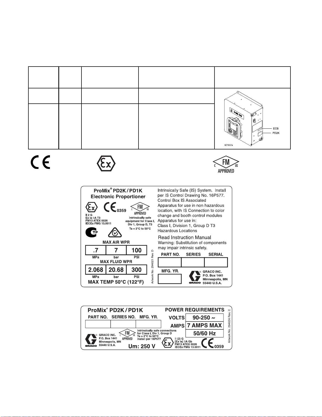
Models
Models
See Figs. 1–6 f
Part No.
AC1000
AC2000
0359
or component identification labels, including approval information and certification.
Series
A
A
Maximum Air Wo
Pressure
100 psi (0.7
7.0 bar)
100 psi (0.7 MPa,
7.0 bar)
MPa,
II 2 G
rking
Maximum Fluid
Pressure
300 psi (2.0
1500 psi (10.34 MPa,
68 MPa, 20.68 bar)
103.4 bar)
Working
Location of PD2K and
Electrical Control Box
(ECB) Labels
Figure 1 Model AC1000 (Low Pressure) Identification
Label
Figure 2 24M672 Control Box Identification Label
4
Continued on the next page.
332564B
Page 5

Figure 3 Model AC2000 (High Pressure)
Identification Label
Models
Figure 4 Non-Intrinsically Safe Color Change Control (Accessory) Identification Label
Figure 5 Intrinsically Safe Color Change Control
(Accessory) Identification Label
Figure 6 Pump Expansion Kit (Accessory) Identification Label
332564B 5
Page 6
Warnings
Warnings
The following
exclamation p
risks. When th
Warnings. Pr
the body of th
warnings are for the setup, use, grounding, maintenance and repair of this equipment. The
oint symbol alerts you to a general warning and the hazard symbol refers to procedure-specific
ese symbols appear in the body of this manual or on warning labels, refer backtothese
oduct-specific hazard symbols and warnings not covered in this section may appear throughout
is manual where applicable.
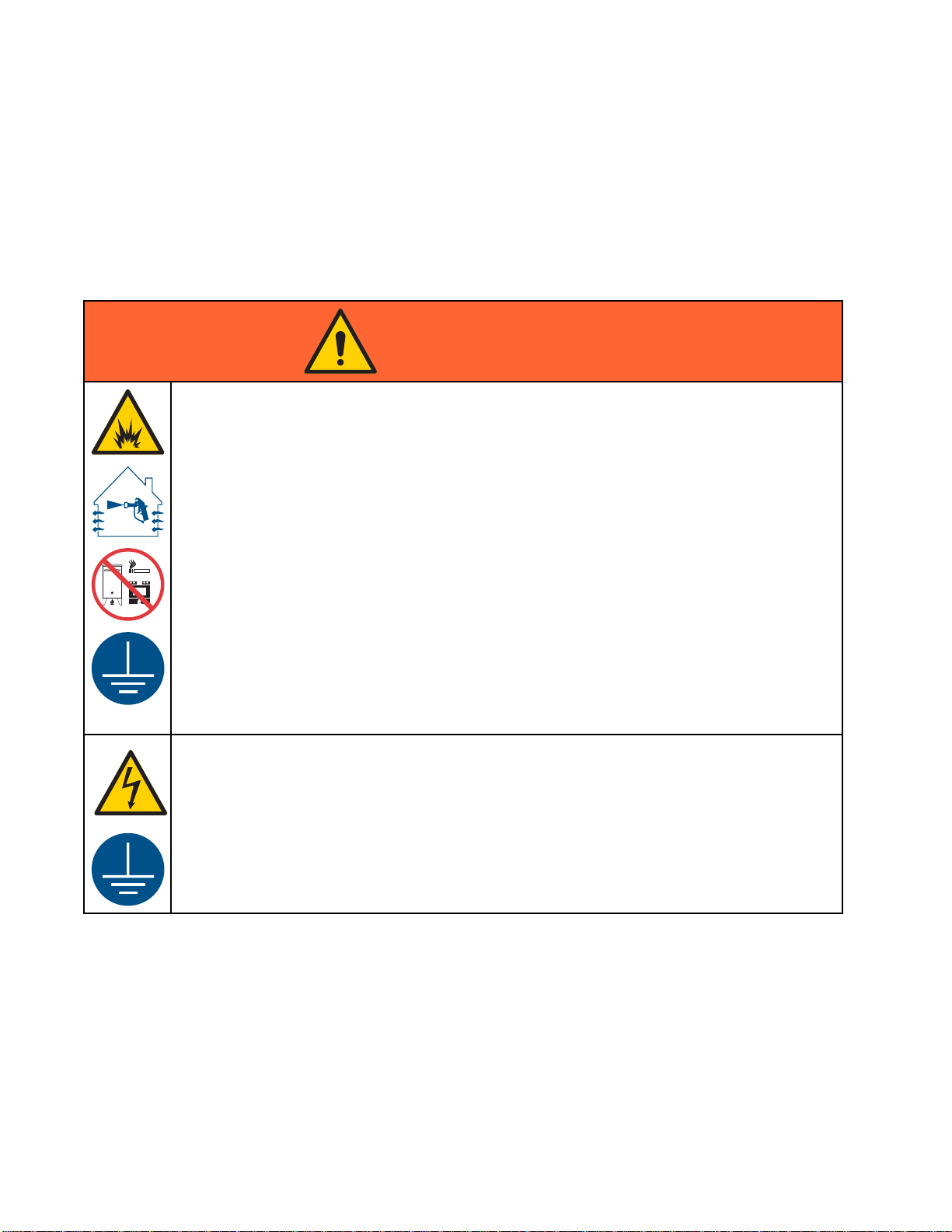
WARNING
FIRE AND EX
Flammable fumes, such as solvent and paint fumes, in work area can ignite or explode. To help
prevent fire and explosion:
• Use equipment only in well ventilated area.
• Eliminate all ignition sources; such as pilot lights, cigarettes, portable electric lamps, and
plastic drop cloths (potential static arc).
• Keep work
• Do not plug or unplug power cords, or turn power or light switches on or off when flammable
fumes are present.
• Ground all equipment in the work area. See Grounding instructions.
•Useonly
• Hold gun firmly to side of grounded pail when triggering into pail. Do not use pail liners unless
they are antistatic or conductive.
• Stop operation immediately if static sparking occurs or you feel a shock, Do not use
equipment until you identify and correct the problem.
• Keepaw
PLOSION HAZARD
area free of debris, including solvent, rags and gasoline.
grounded hoses.
orking fire extinguisher in the work area.
ELECTRIC SHOCK HAZARD
This equipment must be grounded. Improper grounding, setup, or usage of the system can
cause electric shock.
•Turn
• Connect only to grounded power source.
• All electrical wiring must be done by a qualified electrician and comply with all local codes
6 332564B
off and disconnect power at main switch before disconnecting any cables and before
icing or installing equipment.
serv
and regulations.
Page 7
INTRINSIC SAFETY
Warnings
WARNING
Intrinsical
equipment wi
Follow local
• Be sure your installation complies with national, state, and local codes for the installation of
electrical apparatus in a Class I, Group D, Division 1 (North America) or Class I, Zones 1
and 2 (Europe) Hazardous Location, including all of the local safety fire codes (for example,
NFPA 33, NEC 500 and 516, OSHA 1910.107, etc.).
• To help prev
•Equipment
Safety. T
unit from
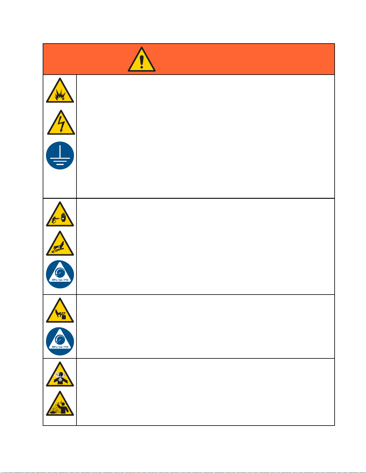
SKIN INJECTION HAZARD
High-pr
skin. Th
immedia
• Do not point dispensing device at anyone or at any part of the body.
•Donotp
• Do not stop or deflect leaks with your hand, body, glove, or rag.
• Follow the Pressure Relief Procedure when you stop dispensing and before cleaning,
checking, or servicing equipment.
•Tight
• Check hoses and couplings daily. Replace worn or damaged parts immediately.
ly safe equipment that is installed improperly or connected to non-intrinsically safe
ll create a hazardous condition and can cause fire, explosion, or electric shock.
regulations and the following safety requirements.
ent fire and explosion:
• Do not install equipment approved only for a non-hazardous location in a hazardous
location. See model ID label for the intrinsic safety rating of your model.
• Do not substitute system components as this may impair intrinsic safety.
that comes in contact with the intrinsically safe terminals must be rated for Intrinsic
his includes DC voltage meters, ohmmeters, cables, and connections. Remove the
the hazardous area when troubleshooting.
essure fluid from dispensing device, hose leaks, or ruptured components will pierce
is may look like just a cut, but it is a serious injury that can result in amputation. Get
te surgical treatment.
ut your hand over the fluid outlet.
en all fluid connections before operating the equipment.
332564B
MOVING PARTS HAZARD
Moving parts can pinch, cut or amputate fingers and other body parts.
• Keep clear of moving parts.
• Do not operate equipment with protective guards or covers removed.
•Pres
TOX
Tox
inh
• Read MSDSs to know the specific hazards of the fluids you are using.
•St
• Always wear chemically impermeable gloves when spraying, dispensing, or cleaning
surized equipment can start without warning. Before checking, moving, or servicing
pment, follow the Pressure Relief Procedure and disconnect all power sources.
equi
IC FLUID OR FUMES
ic fluids or fumes can cause serious injury or death if splashed in the eyes or on skin,
aled, or swallowed.
ore hazardous fluid in approved containers, and dispose of it according to applicable
idelines.
gu
equipment.
7
Page 8

Warnings
WARNING
PERSONAL PROTECTIVE EQUIPMENT
Wear appropriate protective equipment when in the work area to help prevent serious injury,
including eye injury, hearing loss, inhalation of toxic fumes, and burns. This protective
equipment includes but is not limited to:
•Protectivee
• Respirators, protective clothing, and gloves as recommended by the fluid and solvent
manufacturer.
EQUIPMENT MISUSE HAZARD
Misuse can cause death or serious injury.
• Do not operate the unit when fatigued or under the influence of drugs or alcohol.
• Do not exceed the maximum working pressure or temperature rating of the lowest rated
system component. See Technical Data in all equipment manuals.
•Usefluids
in all equ
informat
• Do not leave the work area while equipment is energized or under pressure.
• Turn off all equipment and follow the Pressure Relief Procedure when equipment is not in use.
•Checkeq
manufac
• Do not alter or modify equipment. Alterations or modifications may void agency approvals
and create safety hazards.
• Make sure all equipment is rated and approved for the environment in which youareusingit.
•Useequ
• Route hoses and cables away from traffic areas, sharp edges, moving parts, and hot surfaces.
• Do not kink or over bend hoses or use hoses to pull equipment.
•Keepc
• Comply with all applicable safety regulations.
yewear, and hearing protection.
and solvents that are compatible with equipment wetted parts. See Technical Data
ipment manuals. Read fluid and solvent manufacturer’s warnings. For complete
ion about your material, request MSDS from distributor or retailer.
uipment daily. Repair or replace worn or damaged parts immediately with genuine
turer’s replacement parts only.
ipment only for its intended purpose. Call your distributor for information.
hildren and animals away from work area.
8 332564B
Page 9
Important Isocy
anate (ISO) Information
Important Iso
Isocyanates (ISO) are catalysts used in two
component materials.
cyanate (ISO) Information
Isocyanate Conditions
Spraying or dispensing materials containing
isocyanates creates potentially harmful mists,
vapors, and atomized particulates.
Read and understand material manufacturer’s
warnings and material MSDS to know specific
hazards and precautions related to isocyanates.
Prevent inhalation of isocyanate mists, vapors,
and atomized particulates by providing sufficient
ventilation in the work area. If sufficient ventilation
is not available, a supplied-air respirator is required
for everyone in the work area.
To prevent contact with isocyanates, appropriate
personal protective equipment, including
chemically impermeable gloves, boots, aprons,
and goggles, is also required for everyone in the
work area.
Eventually a film will form on the surface and the ISO
will begin to gel, increasing in viscosity.
NOTICE
Partially c
the life of a
• Always use a sealed container with a desiccant
dryer in the vent, or a nitrogen atmosphere.
Never store ISO in an open container.
• Keep the ISO pump wet cup or reservoir (if
installed) filled with appropriate lubricant. The
lubricant creates a barrier between the ISO and
the atmosphere.
• Use only moisture-proof hoses compatible with
ISO.
• Never use reclaimed solvents, which may
contain moisture. Always keep solvent
containers closed when not in use.
• Always lubricate threaded parts with an
appropriate lubricant when reassembling.
NOTE: The amount of film formation and rate of
crystallization varies depending on the blend of ISO,
the humidity, and the temperature.
ured ISO will reduce performance and
ll wetted parts.
Keep Components A and B Separate
Cross-contamination can result in cured
material in fluid lines which could cause serious
injury or damage equipment. To prevent
cross-contamination:
• Never interchange component A and component
B wetted parts.
• Never use solvent on one side if it has been
contaminated from the other side.
Moisture Sensitivity of Isocyanates
Exposure to moisture (such as humidity) will cause
ISO to partially cure; forming small, hard, abrasive
crystals, which become suspended in the fluid.
Chang
Changing the material types used in your
equipment requires special attention to avoid
equipment damage and downtime.
•When
•Alw
•Che
•Wh
ing Materials
NOTIC
changing materials, flush the equipment
tiple times to ensure it is thoroughly clean.
mul
ays clean the fluid inlet strainers after
hing.
flus
ck with your material manufacturer for
mical compatibility.
che
en changing between epoxies and urethanes
polyureas, disassemble and clean all fluid
or
mponents and change hoses. Epoxies often
co
ve amines on the B (hardener) side. Polyureas
ha
tenhaveaminesontheA(resin)side.
of
E
332564B 9
Page 10

General Informa
tion
General Infor
• Reference numbers and letters in parentheses
in the text refer to numbers and letters in the
illustrations.
• Be sure all accessories are adequately sized and
pressure-rated to meet system requirements.
mation
• To protect the screens from paints and solvents,
clear-plastic protective shields (10 per pack) are
available. Order Part No. 197902 for the Advanced
Display Module. Clean the screens with a dry cloth
if necessary.
10 332564B
Page 11

Advanced Displa
yModule(ADM)
Advanced Disp
lay Module (ADM)
ADM Display
The ADM display shows graphical and text
information related to setup and spray operations.
For detail on the display and individual
screens, see Run Mode Screens, page 58,or
Setup Mode Screens, page 66.
Keys are used to input numerical data, enter setup
screens, navigate within a screen, scroll through
screens, and select setup values.
NOTICE
To prevent damage to the softkey buttons, do not
press the buttons with sharp objects such as pens,
plastic cards, or fingernails.
1. Enable USB dow
Advanced Scr
2. Remove the co
bottom of the
3. During the d
screen.
4. When the dow
appears on t
be removed
NOTE: If th
than 60 sec
determine
Error Sta
the USB.
5. Insert th
the compu
6. The USB fl
If it doe
within W
een 3, page 83.
ver from the USB port on the
ADM. Insert the USB drive.
ownload, USB BUSY appears on the
nload is complete, USB IDLE
he screen. The USB drive may then
.
e download operation takes longer
onds, the message disappears. To
if the USB is busy or idle, check the
tus bar on the screen. If idle, remove
e USB flash drive into the USB port of
ter.
ash drive window automatically opens.
s not, open the USB flash drive from
indows® Explorer.
nloads. See
1 2 3
4 5 6
7 8 9
0 .
Figure 7 Advanced Display Module
USB Download Procedure
the USB port on the ADM to download or upload
Use
a.
dat
7. Open Gra
8. Open sy
more th
one fol
corres
serial
9. Open D
10. Open L
numbe
recen
11. Open
Exce
They
Micr
NOT
(UT
Mic
12. Alw
the
an one system, there will be more than
der. Each folder is labeled with the
ponding serial number of the ADM. (The
number is on the back of the ADM.)
OWNLOAD folder.
OG FILES folder labeled with the highest
r. The highest number indicates the most
t data download.
logfile. LogfilesopeninMicrosoft®
l® by default if the program is installed.
also can be opened in any text editor of
osoft® Word.
E: All USB logs are saved in Unicode
F-16) format. If opening the log file in
rosoft Word, select Unicode encoding.
ays reinstall the USB cover after removing
USB, to keep the drive free of dirt and dust.
co folder.
stem folder. If downloading data from
332564B
11
Page 12

Advanced Displa
yModule(ADM)
USB Upload Pro
Use this procedure to install a system configuration
file and/or a custom language file.
1. If necessary
Procedure, t
folder struc
2. Insert the US
the compute
3. The USB flash
If it does no
within Win
4. Open the Gr
5. Open the sy
than one sy
folder wi
labeled w
the ADM. (
the modul
, follow the USB Download
o automatically generate the proper
ture on the USB flash drive.
r.
t, open the USB flash drive from
dows Explorer.
aco folder.
stem folder. If working with more
stem, there will be more than one
thin the Graco folder. Each folder is
ith the corresponding serial number of
The serial number is on the back of
e.)
cedure
B flash drive into the USB port of
drive window automatically opens.
6. If installing the system configuration settings file,
place SETTINGS.TXT file into UPLOAD folder.
7. If installing the custom language file, place
DISPTEXT.TXT file into UPLOAD folder.
8. Remove the USB flash drive from the computer.
9. Install the USB flash drive into the USB port of
the ProMix PD2K system USB port.
10. During the upload, USB BUSY displays on the
screen.
11. Remove the USB flash drive from the USB port.
NOTE: If the custom language file was installed,
users can now select the new language from the
Language drop-down menu in the Advanced Setup
Screen 1.
2
1
332564B
Page 13

ADM Keys and Indicators
NOTICE
Advanced Displa
yModule(ADM)
To prevent dam
press the butt
plastic card
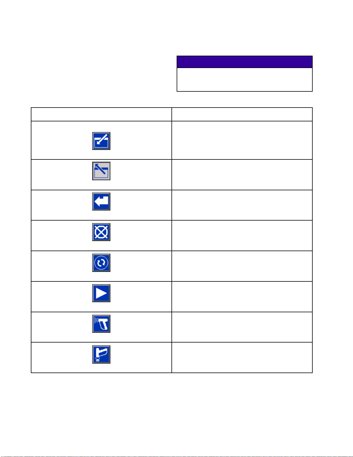
Table 1 : ADM Keys and Indicators
Key Function
Startup/Shutdown
Key and Indicator
Stop
Soft Key
age to the softkey buttons, do not
ons with sharp objects such as pens,
s, or fingernails.
Press to startup or shutdown the pump/motor.
• Solid green indicates that power is applied to the motor.
• Solid yellow indicates that power to the motor is off.
• Blinking green or yellow indicates that the system is in Setup mode.
Press to immediately stop the system and remove motor power.
Press to select the specific screen or operation shown on the display directly next to
each key. The top left soft key is the Edit key, which allows access to any settable
fields on a screen.
s
Left/Right Arrows:
•
Use to move from screen to screen.
Navigation Keys
Numeric Keypad
l
Cance
p
Setu
er
Ent
Up/Down Arrows:
•
menu, or multiple screens within a function.
Use to
Use to cancel a data entry field.
Press to enter or exit Setup mode.
Press to choose a field to update, to make a selection, to save a selection or value, to
enter a screen, or to acknowledge an event.
input values. See ADM Display, page 11.
Use to move among fields on a screen, items on a dropdown
332564B 13
Page 14
Advanced Displa
Soft Key Icons
yModule(ADM)
The following icons appear in the ADM display,
directly to the left or right of the soft key which
activates that operation.
Table 2 : Soft Key Functions
Key Function
Enter Screen
Exit Screen
Accept
To prevent damage to the softkey buttons, do not
press the buttons with sharp objects such as pens,
plastic cards, or fingernails.
Press to enter screen for editing. Highlights editable
data on a screen. Use Up/Down arrows to move
between data fields on the screen.
Press to e
Press to accept calibration value.
Press to cancel or reject calibration value.
NOTICE
xit screen after editing.
Cancel
Prime Pump
Line/Fill/Run
Mix
Purge
Press to start a pump priming procedure.
Press to start a line fill procedure.
Press to start a spray procedure.
Press to start a purge procedure.
4
1
332564B
Page 15
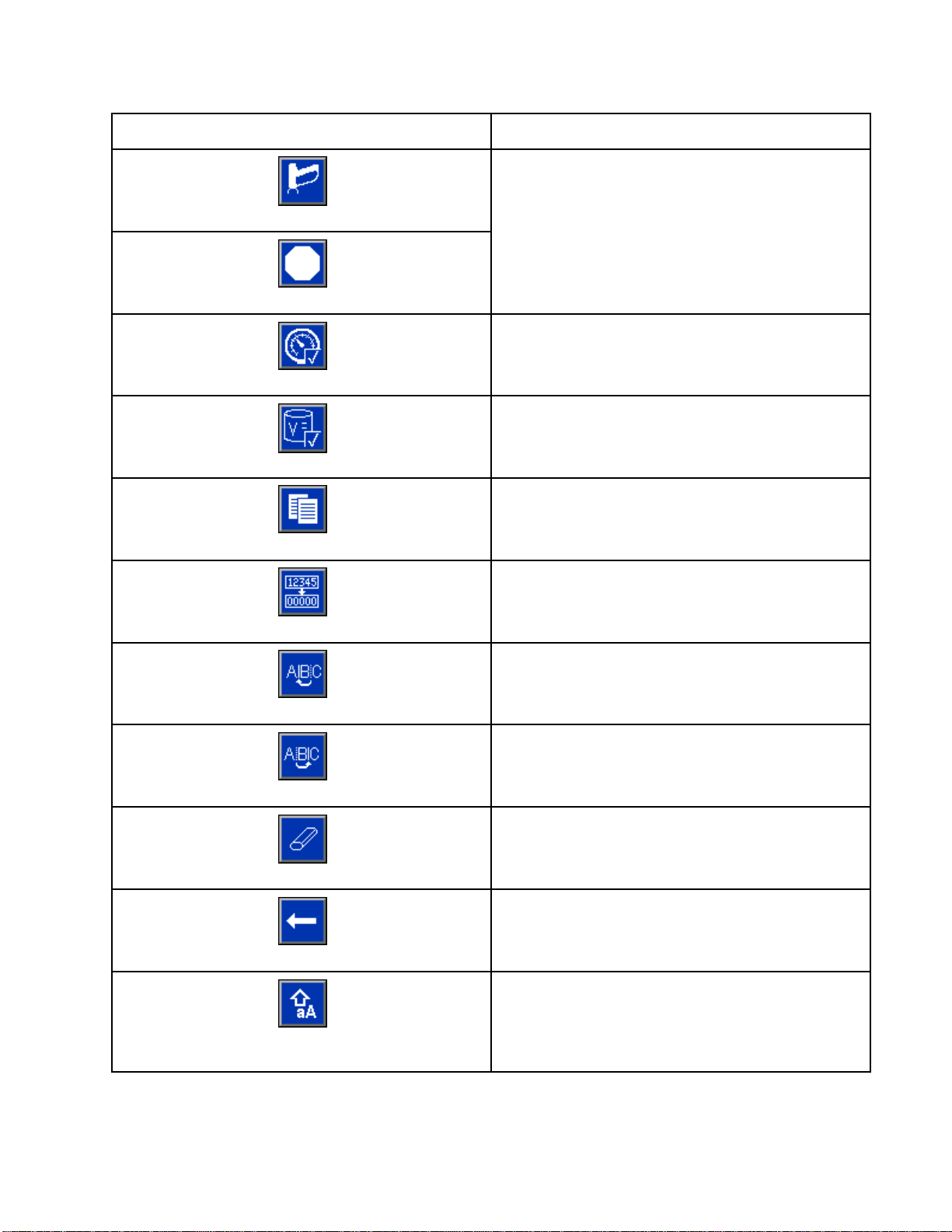
Key Function
Advanced Displa
yModule(ADM)
Standby
Stop
Pressure Check
Volume Check
Job Complete
Counter Reset
Press to stop all pumps and put system in Standby.
Presstostartapumppressurecheck.
Press to st
Press to log the material usage and increment the
job number.
Press to reset the current usage counter.
Appears on the User ID Keyboard screen. Use to
move cursor to the left.
art a pump volume check.
Move Cu
Move Cursor to Right
Upper Case/Lower Case
rsor to Left
Erase All
Backspace
Appears on the User ID Keyboard screen. Use to
move cursor to the right.
Appears on the User ID Keyboard screen. Use to
erase all characters.
ears on the User ID Keyboard screen. Use to
App
se one character at a time.
era
Appears on the User ID Keyboard screen. Use to
change case (upper/lower).
332564B 15
Page 16

Advanced Displa
yModule(ADM)
Navigating th
There are two sets of screens:
• The Run screen
display syst
•TheSetupscr
advanced fea
Press
screens. If the system has a password lock, the
Password screen displays. If the system is not locked
(password is set to 0000), System Screen 1 displays.
Press
Home screen.
Press the Enter soft key
function on any screen.
Press the Exit soft key
Use the other softkeys to select the function adjacent
to them.
e Screens
s control mixing operations and
em status and data.
eens control system parameters and
tures.
on any Run screen to enter the Setup
on any Setup screen to return to the
to activate the editing
to exit any screen.
Screen Icons
As you move through the screens, you will notice
that icons are used frequently to simplify global
communication. The following descriptions explain
what each icon represents.
Screen Icons
User ID
Job Number
Potlife Target Rat
Recipe Number Flow Rate
Pressure Volume
Material B
Material A
Material A+B
Solven
io
t
Calendar Time
Alarm/Advisory
Deviation
16 332564B
Page 17
Pre-Operation T
asks
Pre-Operatio
Pre-operatio
Go through the Pre-Operation Checklist daily, before
each use.
✔
n Checklist
Checklist
System grou
Verify all grounding connections
were made. See Grounding in the
Installation manual.
All connections tight and correct
Verify all
system co
installe
manual.
Fluid supply containers filled
Check co
solvent
nTasks
nded
electrical, fluid, air, and
nnections are tight and
daccordingtotheInstallation
mponent A and B and
supply containers.
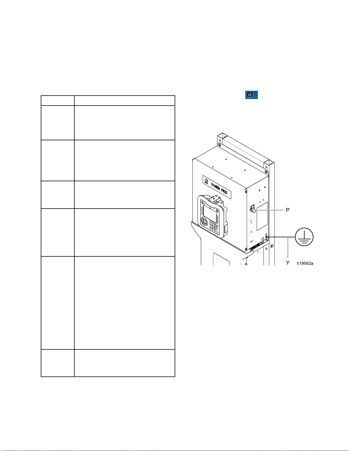
Power On
1. Turn the AC Power Switch (P) ON (I = ON,
0=OFF).
2. The Graco logo will display while the system
initializes, followed by the Home screen.
3. Press the Start key
change from “System Off” to “Startup.” Once
the pumps are powered and are in the Home
position, the system status will change from
“Startup” to “Standby.”
. The system status will
Dose valves set
Check that dose valves are set
1–1/4 turns open. Start with
the settings recommended in
Valve Settings, page 18, then adjust
as needed.
supply valves open and
Fluid
ure set
press
The recommended component A and
B fluid supply pressures are 1/2 to 2/3
of the target spray pressure.
NOTE: Low pressure systems may
be set within a range of ± 100 psi (0.7
MPa, 7 bar); high pressure systems
may be set within a range of ± 300 psi
(2.1 MPa, 21 bar). If the inlet pressure
is higher than the outlet pressure,
ratio accuracy may be affected.
Solenoid pressure set
85-100 psi inlet air supply (0.6-0.7
MPa, 6-7 bar).
Figure 8 Power Switch
332564B
17
Page 18

Pre-Operation T
asks
Initial Syste
1. Change optional setup selections to
desired parameters, as described in
Setup Mode Screens, page 66.
2. Set recipe and flush information as
described in Recipe Screen, page 72 and
Flush Screen, page 73.
m Setup
Flush Before Using Equipment
The pump flui
oil, which
To avoid co
equipment
the equipm
d section was tested with lightweight
is left in the fluid passages to protect parts.
ntaminating your fluid with oil, flush the
with a compatible solvent before using
ent.
Valve Setting
Dose valves and purge valves are factory set with the
hex nut (E) 1-1/4 turns out from fully closed.
Figure 9 Va
s
lve Adjustment
18 332564B
Page 19
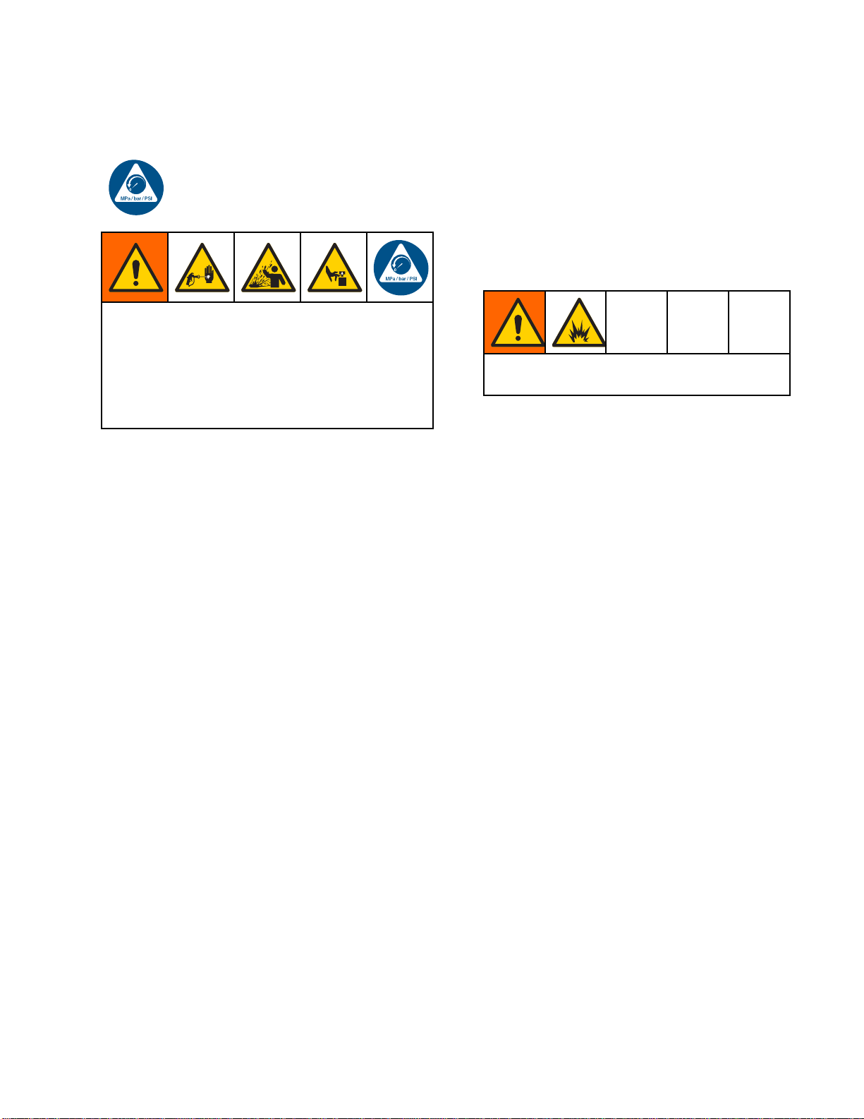
Pressure Relief
Procedure
Pressure Reli
Follow the Pressure Relief Procedure
whenever you see this symbol.
This equipment stays pressurized until pressure
is manually relieved. To help prevent serious
injury from pressurized fluid, such as skin injection,
splashing fluid and moving parts, follow the
Pressure Relief Procedure whenyoustopspraying
and before cleaning, checking, or servicing the
equipment.
ef Procedure
Without Color Change
NOTE: The following procedure relieves all fluid and
air pressure in the system. Use your control interface
to issue the necessary commands to your system.
With Color Change
NOTE: The fol
air pressure
1. Turn off the supply pumps. Open the drain valve
on the supply line fluid filter to relieve pressure in
the supply lines. Do this for each color.
If using an
electrost
2. Trigger the gun to relieve pressure. From
Maintenance Screen 4 on the ADM, check the
box in the field labeled Gun for each color in the
system.
3. Command the system to Purge. Hold the gun
trigger open after the solvent valve shuts off to
relieve all pressure.
lowing procedure relieves all fluid and
in the system.
electrostatic gun, shut off the
atics before flushing the gun.
1. Turn off the supply pumps. Open the drain valve
on the supply line fluid filter to relieve pressure
in the supply line.
2. Command the system to Standby. Trigger the
spray device to relieve pressure.
3. Flush the remote mix manifold and spray device.
See Flush Mixed Material, page 22.
4. Shut off the solvent supply pump. To relieve
pressure, command the system to Purge and
trigger the spray device. When the pressure is
relieved, command the system to Standby to
avoid getting a Purge Incomplete alarm.
5. If pressure remains in the solvent line between
the solvent supply pump and the solvent valve:
• VERY
pres
• Loos
SLOWLY loosen a fitting to relieve
sure gradually.
en the fitting completely.
4. Set the system to Recipe 0 to flush the pumps
and to purge to the spray device. When flushing
is complete the system will go to Standby.
5. Shut off the solvent supply pump. Set the system
to Recipe 0 to flush solvent from the pumps and
to purge to the spray device. Command the
system to Standby after just a couple of seconds,
to avoid getting a Purge Incomplete alarm.
6. If pressure remains in the solvent line between
the solvent supply pump and the solvent valve:
•VERY
pres
• Loos
7. Ver
pum
E: If pressure remains in the solvent line
NOT
ween the solvent supply pump and the solvent
bet
ve,VERYSLOWLYloosenafittingtorelieve
val
essure gradually.
pr
SLOWLY loosen a fitting to relieve
sure gradually.
en the fitting completely.
ify on the ADM Home Screen that neither
p is showing any pressure.
332564B 19
Page 20
Operation Using
Automatic Display Module (ADM)
Operation Usi
Prime and Fill
NOTE: See Run Mode Screens, page 58, for further
screen information, if needed.
NOTE: You mus
or the input
priming the
1. If using an electrostatic gun, shut off the
electrostatics before filling the lines.
2. Adjust the main air pressure. To ensure proper
operation, set the main air pressure as close to
100 psi (0.7 MPa, 7.0 bar) as possible. Do not
uselessthan85psi(0.6MPa,6.0bar).
3. If this is the first time starting up the system, or if
lines may contain air, purge as instructed under
. Flush the System, page 23 The equipment
was tested with lightweight oil, which should be
flushed out to avoid contaminating your material.
s to the color change valves before
pump and filling the entire system.
the System
t prime the input lines to the pumps
ng Automatic Display Module (ADM)
4. If the system is powered down, press
ADM. Make sure that the system is in Standby
mode.
5. Verify that the recipes and the flush sequences
are programmed correctly by checking
the Recipe Screen, page 72 and the
Flush Screen, page 73.
6. Enable the manual override on System Screen 5.
7. Go to the Fill Screen, page 63.
8. Select the desired color to load. Press the Prime
Pump key
through the color stack and out the outlet stack
dump valve.
NOTE: In a single color system, skip step 7 and
prime the pump out to the gun.
9. Press the Fill Line key
the remote mix manifold. The pump will run until
you press the Stop key
. The color will load the pump
to run color out to
to stop the pump.
on the
10. Trigger the gun into a grounded reservoir or
purge receptacle until the line is full, then press
the Stop key
11. Repeat for all material lines.
.
20 332564B
Page 21
Spraying
Operation Using
Automatic Display Module (ADM)
To spray in a multiple color system, also see
Multiple Color Systems, page 87.
NOTE: See Run
screen infor
1. Command the system to Mix. The system will
load the correct mixed material volume.
NOTE: The system will automatically run a Mix
Fill if the recipe is not currently loaded into the
system. The Mix Fill volume calculation includes
the remote mix manifold volume and the mixed
material hose volume. The mixed material hose
volume is determined by the gun hose length and
diameter entered in System Screen 3, page 69,
and the remote to mix hose length and diameter
also entered in System Screen 3, page 69.
Mode Screens, page 58,forfurther
mation, if needed.
2. Adjust the flow rate by changing the target
pressure (in Pressure Mode)orthetargetflow
rate (in Flow Mode) on the Spray Screen or
through the PLC. The fluid flow rate shown on the
Spray screen is the combined total of component
A and B out of the spray device.
NOTE: If spray pressure is adjusted at the ADM
while spraying, it is not saved in the recipe until
the system is put in Standby. This changes the
pressure in the desired recipe.
3. Turn on atomizing air to the gun. Check the spray
pattern as instructed in your spray gun manual.
NOTICE
Do not allow a fluid supply tank to run empty.
This can damage the pumps and lead to the
proportioning of fluid and air that meets the ratio
and tolerance settings of the equipment. This can
further result in spraying uncatalyzed or poorly
catalyzed material.
332564B
21
Page 22
Operation Using
Purging
Automatic Display Module (ADM)
To purge one co
Color Change,
Flush Mixed Ma
There are times when you only want to purge the
remote mix manifold and the spray device, such as:
• end of potlife
• breaks in spraying that exceed the potlife
• overnight shutdown or end of shift
• before servicing the remote mix manifold, hose or
gun.
1. Command the system to Standby.
2. Ifyouareusingahighpressurespraydeviceor
an electrostatic gun, shut off the atomizing air.
lor and fill with a new color, see
page 87.
terial
3. Trigger the spray device to relieve pressure.
4. Set the solvent supply pressure regulator at the
lowest pressure possible. Generally a setting
of 25–50 psi (0.18–0.35 MPa, 1.8–3.5 bar) is
sufficient.
5. CommandthesystemtoPurgeAorPurgeB.
Trigger the spray device into a grounded metal
pail until the purge sequence is complete. When
done purging, the system automatically switches
to Standby mode, signalling the spray device to
stop spraying.
6. If the system is not completely clean, repeat Step
5.
NOTE: For optimal efficiency, adjust purge
sequence times so only one cycle is required.
7. Trigger spray device to relieve pressure.
8. Adjust the solvent supply regulator back to its
normal operating pressure.
NOTE: The remote mix manifold and gun remain full
of solvent after purging.
To reduce risk of fire and explosion, if using
an electrostatic gun, shut off the electrostatics
before flushing the gun.
2
2
332564B
Page 23
Flush the System
Operation Using
Automatic Display Module (ADM)
To avoid fire and explosion, always ground
equipment and waste container. To avoid injury
from splashing, always flush at lowest possible
pressure.
Follow this procedure before:
• the first time material is loaded into the equipment
•servicing
• shutting down equipment for an extended period
of time
• putting equipment into storage
Single Color System
1. Relieve the pressure. See
Pressure Relief Procedure, page 19.
2. Disconnect the color and catalyst supply lines
from the pump inlet manifolds, and connect
regulated solvent supply lines.
3. Set the solvent supply pressure regulator at the
lowest pressure possible. Generally a setting
of 25–50 psi (0.18–0.35 MPa, 1.8–3.5 bar) is
sufficient.
4. Enable manual override on
System Screen 5, page 71.
5. On the ADM, go to the Fill screen. Set the
Color Change S
1. Relieve the pressure. See
Pressure Relief Procedure, page 19.
2. Attach regulated solvent supply lines as follows:
• Multiple color/single catalyst system: On the
color side, do not disconnect the color supply
line from the inlet manifold of Pump A. Instead,
connect a regulated solvent supply line to the
designated solvent valve on the color valve
manifold. On the catalyst side, disconnect
the catalyst supply line from the inlet manifold
of Pump B, and connect a regulated solvent
supply line.
• Multiple color/multiple catalyst system:
Connect regulated solvent supply lines to
the designated solvent valves on the color
and catalyst valve manifolds. Do not connect
solvent supply lines directly to the inlet
manifolds of the pumps.
3. Set the solvent supply pressure regulator at the
lowest pressure possible. Generally a setting
of 25–50 psi (0.18–0.35 MPa, 1.8–3.5 bar) is
sufficient.
4. On the ADM, go to the Fill screen. Set the
Material to Solvent. Press
will pump solvent from the color valve inlet all the
way to the gun.
5. Hold a metal part of the gun firmly to a grounded
metal pail. Trigger the gun until clean solvent
dispenses.
6. Repeat for each color line.
ystem
. The system
Material to Color (A). Press
will pump solvent through pump A all the way to
the gun.
6. Hold a metal part of the spray device firmly to a
grounded metal pail. Trigger the spray device
until clean solvent dispenses.
7. On the ADM, go to the Fill screen. Set the
Material to Catalyst (B). Press
system will pump solvent through pump B all the
way to the gun.
8. Relieve the pressure. See
Pressure Relief Procedure, page 19
. The system
.The
7. Relieve the pressure. See
Pressure Relief Procedure, page 19
down
Shut
1. Flush out the mixed material to avoid potlife errors
and fluid setup in the lines. See Purging, page 22.
2. Follow the Pressure Relief Procedure, page 19.
3. Close the main air shutoff valve on the air supply
line and on the control box.
4. Press
power to the pumps.
5. Shut off system power (0 position).
on the Display Module to turn off
332564B 23
Page 24

Operation Using
a Programmable Logic Controller (PLC)
Operation Usi
ng a Programmable Logic Controller
(PLC)
Network Communications and Discrete I/O
The ProMix PD2K Automatic system does not use
a Booth Control module. Instead, it uses Network
Communications and has optional Discrete I/O
features to drive the system remotely.
Some automation control elements of the
ProMix PD2K can be driven by a discrete
input
or
network communications. These
options need to be configured at the ADM (see
System Screen 5, page 71). The following features
can be set to ‘Discrete’ or ‘Network’:
• Flow Cont
point (s
• Gun Trig
when the
NOTE: Th
user to
(PLC) i
run all
signal
mode of
Overri
avoid
the au
rol – Means of adjusting the control set
ee Flow Control Set Point below).
ger – Means of signaling the ProMix PD2K
spray device is triggered.
e Manual Override check box enables a
operate the system before the automation
s available. Manual Override can be used to
functions of the system if a proper gun trigger
is provided. It is not intended to be the main
control. Graco recommends that Manual
de be disabled during normal operation to
driving the system in a way that conflicts with
tomation sequence.
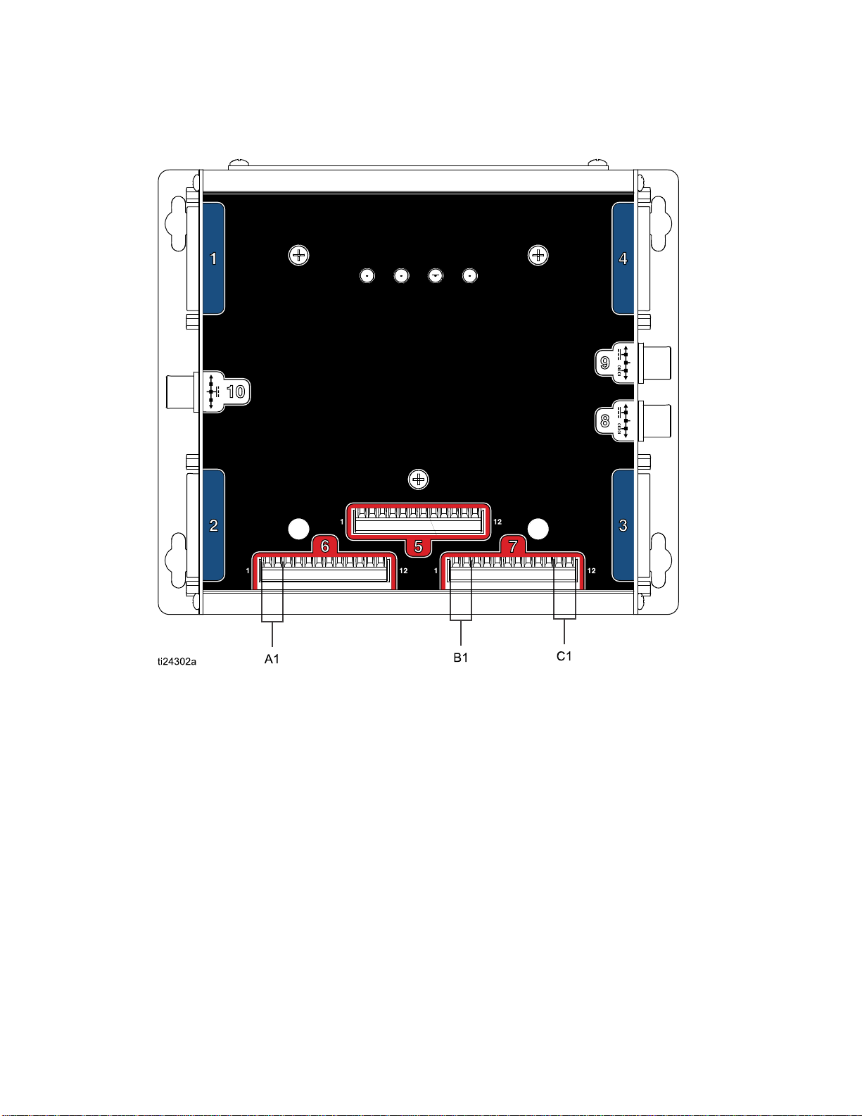
Discrete I/O
The ProMix PD
Discrete I/
is necessar
with the PLC
connection
strips on t
inside the
Table 3 and Figure 2 show where discrete I/O
connections are made on the ProMix PD2K.
Table 3 PD2K Discrete I/O Connections
I/O
Description
Gun Trigger
Input
lSet
Contro
Point
Safety
Interlock
Input
2K does not supply power for
O. A clear understanding of these inputs
y to properly integrate the ProMix PD2K
or networking device. Input and output
s are made at the Discrete I/O terminal
he Enhanced Fluid Control Module (EFCM)
control box.
EFCM
Connector
61,2
7
7
Pins Type
Normally Open
Contact
1,2 4-20 mA Input
11,12
Normally Open
Contact
4
2
332564B
Page 25
Operation Using
a Programmable Logic Controller (PLC)
Digital Inputs
• Safety Interlock: This normally open contact works
like a soft emergency stop button. If the ProMix
PD2K reads the input as CLOSED it interrupts
system operation and removes power from the
pumps regardless of the current operating mode.
If the input is read as OPEN, the system operates
normally
NOTE: This digital input is always enabled.
Do not toggle this input to put the system into
Standby mode.
• Gun Trigger: This normally open (maintained)
contact provides a signal to the system to indicate
whether or not a spray device is triggered. This
input provides timing for alarm functions and also
drives the flow control algorithm. If the input is
OPEN the system operates as though the spray
device is off. The input must be maintained
CLOSED to signal that the spray device is
triggered.
NOTE: The Gun Trigger discrete input must be
enabled via Configure Screen 5 on the ADM. If it
is set to ‘Network’ the discrete input is ignored and
the spray device trigger signal is handled via the
network communications.
If enabled, it is imperative that this signal be sent
any time the spray device is triggered. Without the
signal, the flow control features will not work.
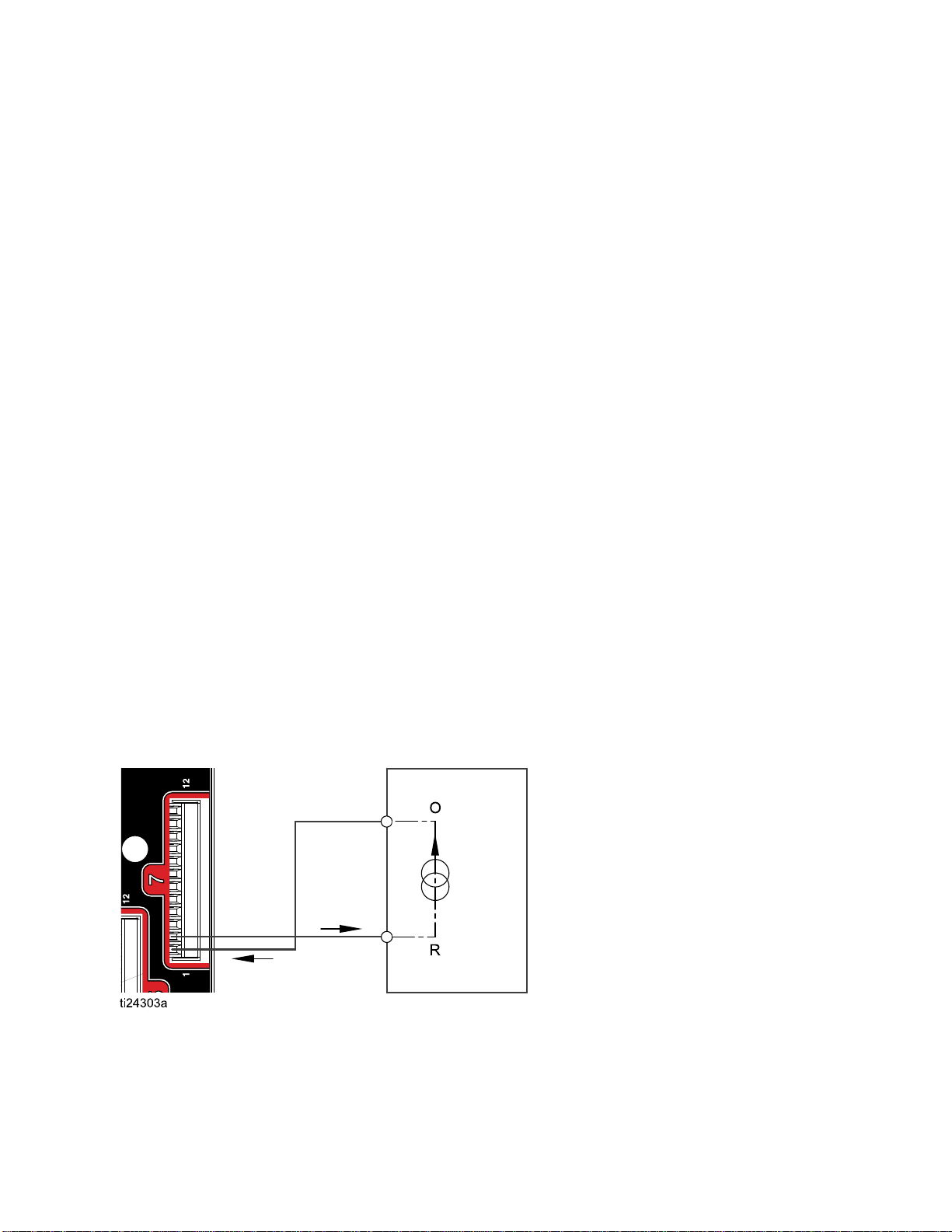
Analog Inputs
Flow Control Set Point: When enabled, this 4-20mA
signal input is used to set and adjust the operating
flow control set point. The ProMix PD2K scales the
set point linearly from 0 to the Max Set Point setting
(see System Screen 5, page 71).
• In Flow Cont
cc/min, a 4m
is 500 cc/mi
• In Pressur
500 psi, a 4
is 500 psi.
NOTE: The Flow Control discrete input must be
enabled via Configure Screen 5 on the ADM. If
set to ‘Network’ the discrete input is ignored and
set point adjustment is handled via the network
communications.
rol Mode: If the Max Set Point is 500
A signal is 0 cc/min and a 20mA signal
n.
e Control Mode: If the Max Set Point is
mA signal is 0 psi and a 20mA signal
Examples
,
PD2K Discrete Input
e10
Figur
4–20 mA
Flow Control Set Point Input
PLC (4–20 MA Signal)
O = Output
R=Return
332564B 25
Page 26
Operation Using
Figure 11
a Programmable Logic Controller (PLC)
Discrete I/O Connections on EFCM
KEY
A1
B1
C1 Safety Interlock Input
Gun Trigger Input
og Set Point Input
Anal
26 332564B
Page 27

Operation Using
a Programmable Logic Controller (PLC)
Communicatio
n Gateway Module (CGM) Details
CGM Overview
The CGM provides a control link between the PD2K
system and a selected fieldbus. This linkage provides
the means for remote monitoring and control by
external automation systems.
NOTE: The fo
files are ava
• EDS file: DeviceNet or Ethernet/IP fieldbus
networks
• GSD file: PROFIBUS fieldbus networks
• GSDML file: PROFINET fieldbus networks
llowing system network configuration
ilable at www.graco.com.
CGM Kits
The PD2K system comes with a Modbus TCP CGM.
Kits for other communication protocols are available.
Each kit includes all parts needed to install the
CGM, along with Manual 334494, which contains
installation instructions applicable to any kit. See
Manual 312864 or Manual 334183 for information
specific to each protocol, plus repair parts for each
assembly.
CGM Part No.
CGMDNO
CGMEPO
CGMPBO PROFIBUS
CGMPNO PROFINET
24W462
Fieldbus Manual
DeviceNet 312864
EtherNet/
Modbus TCP
IP
312864
312864
312864
334183
332564B
27
Page 28

Operation Using
a Programmable Logic Controller (PLC)
Network Commu
nication I/O Data Map
ProMix PD2K Network Outputs
The ProMix PD2K Network Outputs are Read-Only
and should be treated as inputs to a PLC
or other networking device. These registers
OUTPUT REGIS
The Current System Mode register contains a number that indicates the current operation mode of the PD2K
system.
Number
1
2
3
4
5
TER 00: Current System Mode
Operation Mode
Pump Off
Recipe Change The system is in the process of a color change sequence.
Recipe Change: PurgeAThe system is purging material A as part of a recipe change.
Recipe C
B
Recipe Change: Fill The system is filling the hose from the remote valves to the mix
hange: Purge
Description
The pumps a
operation
The syst
manifold with material as part of a recipe change.
em is purging material B as part of a recipe change.
provide various system and component status,
measurement, and set point values. See
Network Output Data Map (Read Only), page 33.
re currently powered down and the system is not in
.
6MixFil
7
8MixI
9 Purge A
10 Purge B
11
12
3
1
14
l
Mix The system is currently mixing/spraying material.
dle
Standby: Mix Ready
andby: Fill Ready
St
Standby: Mix Not Ready
Standby: Alarm
The system is mixing material at ratio through the mix manifold
and out the gun.
The system has paused mix operation due to the absence of a gun
trigger signal.
system is purging material A while in Standby.
The
The system is purging material B while in Standby.
e system has a valid recipe loaded out to the gun.
Th
The system has a valid recipe loaded in the pumps, but not in the
gun.
he system requires that a recipe change operation be completed.
T
The system has an active alarm.
28 332564B
Page 29

Operation Using
a Programmable Logic Controller (PLC)
OUTPUT REGISTERS 01, 02, 03, and 04: Pump
Status
ThePumpStatu
indicates the
be used for gen
or as an indica
operations.
Pump Command
Table4PumpS
Nu-
Pump
m-
State
ber
0
Off
1
Standby
2 Busy The pump i
3 Flushing
s registers contain a number that
state of Pumps 1 — 4. This status can
eral monitoring of the pump state,
tor for driving independent pump
See INPUT REGISTER 02: Flush/Prime
, page 36.
tates for Output Registers 01–04
Description
The pump is powered down or
not enabled.
The pump is powered but not
currently active.
s currently in
arecipec
operatio
The pump is currently flushing
with solvent
hange or mixing
n.
OUTPUT REGISTER 07: Actual Mix Potlife
Remaining
The Actual Pot
the current am
recipe’s potl
NOTE: If potlife is disabled for the active recipe or at
initial startup this value will be 0xFFFFFFFF.
OUTPUT REGISTER 08: Active Recipe Number
TheActiveR
number of th
• This value is 0 if the system was flushed.
• This value is 61 if the system does not know the
current loaded recipe, if the recipe is invalid, or at
initial startup.
OUTPUT REGISTER 09: Active Recipe Material A
The Activ
number of
the curre
life Remaining register contains
ount of time remaining in the active
ife in seconds.
ecipe Number register contains the
eactiverecipe(1–60).
e Recipe Material A register contains the
the Color (1 – 30) that is associated with
nt recipe.
4 Priming The pump
with mat
OUTPUT REGISTER 05: Actual Mix Flow
The Act
insta
NOTE: This register is valid only during a mix
operation.
OUTPUT REGISTER 06: Actual Mix Ratio
The A
inst
• The value reported is the ratio antecedent
Example
(Material A to Material B)
•Ift
This register is valid only during a mix operation.
ual Mix Flow register reports back the
ntaneous mixing flow rate in cc/min.
ctual Mix Ratio register contains the
antaneous calculated mix ratio.
multiplied by 100. The ratio consequent is always
1.
: Value = 250 >> A mix ratio of 2.5:1
he current recipe ratio is 0:1 (1K recipe) this
lue will be 0.
va
is currently priming
erial.
• This value is 0 if the system was flushed.
• This value is 61 if the current recipe is invalid or at
initial startup.
OUTPUT REGISTER 10: Active Recipe Material B
The Act
the num
with t
• This value is 0 if the system was flushed.
• This value is 61 if the current recipe is invalid or at
• This value is 0 if the current recipe ratio is 0:1 (1K
OUTPUT REGISTER 11: Active Recipe Material A
Flush Sequence
The
reg
(1 –
cur
If the current recipe is invalid this value reflects the
Flush Sequence associated with Material A pump
of recipe 0.
ive Recipe Material B data register contains
ber of the Catalyst (31 – 34) that is associated
he current recipe.
initial startup.
recipe).
Active Recipe Material A Flush Sequence
ister contains the number of the Flush Sequence
5) that is associated with the Color pump of the
rent recipe.
332564B 29
Page 30

Operation Using
a Programmable Logic Controller (PLC)
OUTPUT REGISTER 12: Active Recipe Material B
Flush Sequence
The Active Recipe Material B Flush Sequence
register contains the number of the Flush Sequence
(1 – 5) that is associated with the Catalyst pump of
the current recipe.
• If the current recipe is invalid this value reflects the
Flush Sequence associated with Material B pump
of recipe 0.
• This value is 0 if the current recipe ratio is 0:1 (1K
recipe)
OUTPUT REGISTER 13: Active Recipe Ratio Set
Point
The Active Recipe Ratio Set Point data register
contains the ratio set point associated with the
current recipe.
• The value reported is the ratio antecedent
multiplied by 100. The ratio consequent is always
1.
Example
(Material A to Material B)
• This value is 0 if the current recipe ratio is 0:1 (1K
: Value = 250 >> A mix ratio of 2.5:1
recipe)
OUTPUT REGISTER 19: Actual Pump 1 Fluid
Pressure
OUTPUT REGIST
Pressure
OUTPUT REGISTER 21: Actual Pump 3 Fluid
Pressure
OUTPUT REGISTER 22: Actual Pump 4 Fluid
Pressure
These regis
pressure on
OUTPUT REGISTER 23: Gun 1 Trigger Input Status
The Gun 1 Trigger Input Status register contains the
status of the Gun Trigger Discrete Input.
•Thevaluei
triggere
•Thevalue
triggere
This data register is valid only for systems configured
to use the discrete input for the Gun Trigger.
d).
d).
Gun Trigger Signal, page 71
OUTPUT REGISTER 24: Gun 2 Trigger Input Status
ER 20: Actual Pump 2 Fluid
ters contain the instantaneous fluid
the outlet of pumps 1–4 in PSI.
s0iftheinputisOPEN(gunnot
is 1 if the input is CLOSED (gun
See
.
OUTPUT REGISTER 14: Active Recipe Potlife
Timeout Set Point
The Active Recipe Potlife Timeout Set Point register
contains the set point for the potlife time associated
with the current recipe in minutes.
• This value is 0 if the potlife time is disabled for the
current recipe.
OUTPUT REGISTER 15: Actual Pump 1 Flow Rate
OUTPUT REGISTER 16: Actual Pump 2 Flow Rate
OUTPUT REGISTER 17: Actual Pump 3 Flow Rate
OUTPUT REGISTER 18: Actual Pump 4 Flow Rate
These registers contain the instantaneous flow rate
of Pumps 1–4 in cc/min.
This is NOT the mix flow rate. For mix flow rate see
Actual Mix Flow
.
OUTPUT
OUTPUT REGISTER 26: Gun 4 Trigger Input Status
REGISTER 25: Gun 3 Trigger Input Status
These registers are not used.
OUTPU
Statu
The Safety Interlock Input Status register contains
the status of the Safety Interlock Discrete Input.
• The value will be 0 if the input is OPEN (Normal).
• The value will be 1 if the input is CLOSED (Safety
See
OUTPUT REGISTERS 28 – 36: DCS Command
Structure
See Dynamic Command Description, page 47.
T REGISTER 27: Safety Interlock Input
s
Stop).
Safety Interlock in Digital Inputs, page 25
.
30 332564B
Page 31

Operation Using
a Programmable Logic Controller (PLC)
OUTPUT REGISTER 37: Time
TheTimeregis
since the Unix
• The actual value reported is not important. This
register should be used for diagnosing status of
communication between the ProMix PD2K and the
networking device.
This register is NOT currently available with the
Modbus Communications Gateway Module.
ter contains a count of total seconds
Epoch (January 1, 1970).
OUTPUT REGISTER 38 – 40: Software Version
The Software V
“minor,” and “
These registers are NOT currently available with the
Modbus Communications Gateway Module.
ersion registers contain the “major,”
build” revisions of the ADM software.
332564B 31
Page 32

Operation Using
Notes
a Programmable Logic Controller (PLC)
32 332564B
Page 33

Operation Using
Network Output Data Map (Read Only)
a Programmable Logic Controller (PLC)
Network
Output ID
00 40100
Modbus
Register
Parameter Name Data Type Units Range
uint32
Current Syste
Mode
m
NONE
1=PumpOff
2 = Recipe Change
3 = Recipe Change:
Purge A
4=RecipeCh
Purge B
5 = Recipe Change: Fill
6=MixFil
7=Mix
8=MixIdle
9=Purge
10 = Purge B
11 = Sta
12 = Standby: Fill Ready
13 = Standby: Mix Not
Ready
14 = S
ange:
l
A
ndby: Mix Ready
tandby: Alarm
01 40102
02 40104
03 40106
Pump 1 Status
ump 2 Status
P
Pump 3 Status
uint32
uint32
uint32
NONE
ONE
N
NONE
0=Off
1 = Standby
2=Busy
Flushing
3=
4 = Priming
=Off
0
1 = Standby
2=Busy
3 = Flushing
4 = Priming
0=Off
1 = Standby
2=Busy
3 = Flushing
4 = Priming
332564B 33
Page 34

Operation Using
a Programmable Logic Controller (PLC)
04 40108
05 40110 Actual Mix Flow uint32 cc/min 1 - 1600
06 40112 Actual Mix Ratio uint32
07 40114
08 40116 Active Re
09 40118 Active Recipe
10 40120 Active Recipe
11 40122 Active
12 40124 Active Recipe
Pump 4 Status
Actual Mix Potlife
Remaining
cipe
Number
Material A
Material B
Recipe
al A Flush
Materi
Sequen
Material B Flush
Sequence
ce
uint32
uint32
uint32
uint32
uint32
uint32
uint32
NONE
NONE
sec
NONE
NONE
NONE
NONE
NONE
0=Off
1 = Standby
2=Busy
3 = Flushing
4 = Priming
0 - 5000
0 – 59940
0-61
1-30,61
31 - 34, 61
1-5
1-5
13 40126 Active Recipe
Ratio Set Point
0140
4
8
134
14 4012
15 40130 Actual Pump 1
16 40132 Actual Pump 2
17 40
18 40136 Actual Pump 4
19 40138 Actual Pump 1
0
2
21 40142 Actual Pump 3
22 40144 Actual Pump 4
ve Recipe
Acti
ife Time Set
Potl
t
Poin
Flow Rate
Flow Rate
tual Pump 3
Ac
ow Rate
Fl
Flow Rate
Fluid Pressure
ctual Pump 2
A
Fluid Pressure
Fluid Pressure
Fluid Pressure
uint32
32
uint
uint32 cc/min 0 - 800
uint32 cc/min 0 - 800
nt32
ui
uint32 cc/min 0 - 800
uint32
int32
u
uint32
uint32
NONE
min 0 - 99
/min
cc
SI
P
PSI
PSI
PSI
0 - 5000
800
0-
0 - 1500
-1500
0
0 - 1500
0 - 1500
9
34 332564B
Page 35

Operation Using
a Programmable Logic Controller (PLC)
23 40146
24 40148
25 40150
26 40152
27 40154
28 40200
29 40202
30 402
04
Gun 1 Trigger
Input Status
Gun 2 Trigger
Input Status
Gun 3 Trigge
Input Stat
Gun 4 Trigger
Input Status
Safety Interlock
Input Status
Comman
Acknow
Command Return
0
Command Return
1
r
us
d
ledge
uint32
uint32
uint32
uint32
uint32
uint32
uint32 N/A N/A
t32
uin
NONE
NONE
NONE
NONE
NONE
NONE
N/A N/A
0 = Gun not triggered
1 = Gun trigger
0 = Gun not triggered
1 = Gun triggered
0=Gunnottr
1 = Gun triggered
0 = Gun not triggered
1=Guntri
0=Open
1 = Closed
0:=NOP
1=BUSY
2=ACK
3=NAK
4=ER
ed
iggered
ggered
R
31 40206
32 40208
33 40210
34 40212
35 40214
36 40216
37 N/A Time uin32
38 N/A
39 N/A
40 N/A
mmand Return
Co
2
Command Return
3
Command Return
4
Command Return
5
Command Return
6
Command Return
7
Software Version
–Major
Software Version
–Minor
Software Version
– Build
uint32 N/A N/A
uint32 N/A N/A
uint32 N/A N/A
uint32 N/A N/A
uint32 N/A N/A
uint32 N/A N/A
uint32
uint32
uint32
sec
NONE
NONE
NONE
0 – 4,294,967,295
0–99
0–99
0–999
These registers are not used.
DCS Register
332564B 35
Page 36

Operation Using
a Programmable Logic Controller (PLC)
ProMix PD2K Network Inputs
The ProMix PD2K Network Inputs are Write-Read capable, but should be treated as outputs from a PLC or
other networking device. These registers allow the user to control system operation and configure system
settings remotely. Invalid values (i.e. out of bounds or not consistent with system configuration) will be ignored
by the ProMix PD2K. All values must be written as integers. Floating point numbers are not supported.
Do not rely on
NOTE: The PD2K system does not refresh the values for these registers. At power up all input registers
initialize to invalid values.
INPUT REGISTER 00: System Mode Command
The System M
to initiate
Figures 5 –
Number
1
2 Power Pumps
3
4
5
6Mix Thesy
7
8 Purge B The system purges only Material B out through the gun.
these registers for Read status, other than to confirm data that has been written and accepted.
ode Command register accepts a number that represents a command to the PD2K system
a particular operation. Some operation modes may be initiated only under certain conditions (see
9 for details).
Operation Mode
No OP
Remote Stop The system stops all current operations and turns off power to the
Recipe
Mix Fill
Purge A The system purges only Material A out through the gun.
Change
Descripti
The system takes no action.
The system powers on or powers off the pumps.
pumps.
The sys
The system fills the mix manifold and gun with material at ratio for
a valid recipe.
on
tem initiates a recipe change. (See also Register 7.)
stem initiates a mix/spray cycle.
9
Standby The system puts all active pumps into Standby mode.
36 332564B
Page 37

Operation Using
a Programmable Logic Controller (PLC)
INPUT REGISTER 01: Pump Flush Sequence/Prime
Material Selection
ThePumpFlush
register is us
Pump Command r
below) to inde
pump.
• Write a value between 1 and 5 if flushing a pump.
• Write a value between 1 and 30 if priming a Color
pump.
• Writeavaluebetween31and34ifpriminga
Catalyst pump.
NOTE: It is important that the user know which
material is assigned to each pump. An invalid
selection will be ignored by the ProMix PD2K.
INPUT REG
The Flush/Prime Pump Command register is used in
conjunction with the Pump Flush Sequence/Prime
Material Selection register (see INPUT REGISTER
01) to independently prime or flush an inactive pump.
The desired pump MUST be in Standby mode.
Confirm by reading the corresponding Pump Status
output register (see OUTPUT REGISTERS 01 – 04).
Sequence/Prime Material Selection
ed in conjunction with the Flush/Prime
egister (see INPUT REGISTER 02
pendently prime or flush an inactive
ISTER 02: Flush/Prime Pump Command
INPUT REGISTER 03: Mix (Pump 1) Control Set
Point
The Mix Contro
adjust the mix
as the fluid con
a1Krecipe. It
system will i
• If the system is configured for Flow Control this
value can be set between 5 and 1600 cc/min for a
2K recipe, and between 5 and 800 for a 1K recipe.
See Fluid Control on System Screen 5, page 71.
• If the system is configure for Pressure Control this
value can be set between 0 and the maximum
pump pressure in PSI. See Fluid Control on
System Screen 5, page 71.
NOTE: The Flow Control must be configured to
‘Network’ via System Screen 5 on the ADM. If set
to ‘Discrete’ this register is ignored and set point
adjustment is handled via the discrete input. See
Analog Inputs, page 25.
INPUT REG
INPUT REGISTER 05: Pump 3 Control Set Point
INPUT REGISTER 06: Pump 4 Control Set Point
l Set Point register is used to set and
ing fluid control set point. It also is used
trol set point for pump 1 when running
can be changed at any time, and the
mmediately adjust to the new set point.
ISTER 04: Pump 2 Control Set Point
If an invalid Flush Sequence or invalid material
number is written to the Pump Flush Sequence/Prime
Material Selection register then the Flush/Prime
command will be ignored. The user must know
what material is assigned to each pump. (See
Color Change Kits Instruction Manual 332455 for
color/catalyst pump mapping.)
NOTE:
inact
conti
the s
is co
mode
oper
If two pumps are currently mixing and an
ive pump is commanded to flush or prime it will
nue its operation to completion without affecting
ystem mode status. When the mixing operation
mplete, the system status will reflect Standby
while the flushing/priming pump completes its
ation.
These r
INPUT REGISTER 07: Go to Recipe Number
The Go to Recipe Number register is used as a
queue for the next recipe to be loaded when a recipe
change is initiated. A number between 0 and 60 can
be written to this register. However, a recipe must be
enabled via the ADM before it can be loaded. See
Recipe Screen, page 72.
NOTE
chan
egisters are not used.
: Writing to this register does not trigger a recipe
ge.
See Color Change Sequence, page 44.
332564B 37
Page 38

Operation Using
a Programmable Logic Controller (PLC)
INPUT REGISTER 08: Clear Active Alarm
The Clear Acti
acknowledge a
may resume ope
condition has
register to ac
more than one
recent alarm
should be per
alarms. See fi
ve Alarm register is used to
n alarm remotely so that the system
ration. Be sure that the alarm
been alleviated. Write a 1 to this
knowledge the latest active alarm. If
alarm is currently active only the most
will be acknowledged. A repeated write
formed to clear any remaining active
gure 9.
(See System Errors, page 88 for more information
on clearing alarms.)
NOTE: This register is not polled by the ProMix
PD2K. An alarm is cleared only when a value of ‘1’
is written to this register. It is recommended that the
automation reset this register by writing a 0 to it at all
other times to avoid inadvertently clearing an alarm.
INPUT REG
ISTER 09: Job Complete
The Job Complete register is used to log the current
job remotely. Write a ‘1’ to the register to command
theProMixPD2Ktoflagajobcomplete.
INPUT REGISTER 10: Gun 1 Trigger
TheGun1Trigg
ProMix PD2K wh
triggered. Th
spray device i
provides timi
the flow contr
er register is used to signal the
en the automatic spray device is
is signal should be sent any time the
s triggered. The state of this register
ng for alarm functions and also drives
ol algorithm.
NOTE: If enabled, it is imperative that this signal be
sent any time the spray device is triggered. Without it
the flow control features will not work.
• Write a value of ‘1’ to signal that the gun is
triggered.
• Write a value of ‘0’ to signal that the gun is NOT
triggered.
NOTE: This
is set to ‘N
If it is se
gun trigg
Digital I
critical
provide a
register is used only if the Gun Trigger
etwork’ via System Screen 5 on the ADM.
t to ‘Discrete’ this register is ignored and
er is handled via the discrete input. See
nputs, page 25.
NOTE: Because timing is so
for flow control Graco recommends that users
discrete input to minimize latency effects.
(See Usage Screen, page 64 for more information on
Job Logs and Job Complete.)
NOTE: Th
PD2K. A
is writ
automa
other t
is register is not polled by the ProMix
job is logged only when a value of ‘1’
ten to this register. It is recommended the
tion reset this register by writing a 0 to it at all
imes to avoid inadvertently logging a job.
Input Register 10
Gun Trigger
Discrete Signal
ProMix PD2K
Gun Trigger State
e 12 Gun Trigger Timing (Network and Discrete
Figur
ls Shown
Signa
10 1 0
INPUT REGISTER 11: Gun 2 Trigger
INPUT REGISTER 12: Gun 3 Trigger
T REGISTER 13: Gun 4 Trigger
INPU
These registers are not used.
INPUT REGISTERS 14 – 21: DCS Command
Structure
e Dynamic Command Description, page 47.
Se
38 332564B
Page 39

Notes
Operation Using
a Programmable Logic Controller (PLC)
332564B 39
Page 40

Operation Using
a Programmable Logic Controller (PLC)
Network Input Data Map (Write/Read)
Network
Input ID
00 40156
01 40158
02 40160
Modbus
Register
Parameter Name Data
Type
System Mode Co
Pump Flu
Materia
Flush/Prime Pump Command
sh Sequence #/Prime
l#
mmand
uint32
uint32
uint32
Units Range
NONE
NONE
NONE
0=No
1=PowerPump
2=RemoteStop
3 = Recipe Change
4 = Mix Fill
5=Mix
6=PurgeA
7=PurgeB
8 = Standby
1 - 5, 1 - 34
0=NoOP
1=Flus
2=PrimePump1
3=FlushPump2
4=Pri
s
hPump1
me Pump 2
03 40162
0170
4
164
04 40
05 40166
06 40168
7
0
08 40172
09 40174
10 40176
11 40178
(Pump 1) Control Set Point
Mix
Pump 2 Control Set Point
Pump 3 Control Set Point
ump 4 Control Set Point
P
Go to Recipe Number
Clear Active Alarm
Job Complete
Gun 1 Trigger
Gun 2 Trigger
uint32 cc/min or
PSI
nt32
ui
uint32 cc/min or
uint32 cc/min or
int32
u
uint32
uint32
uint32
uint32
/min or
cc
I
PS
PSI
PSI
NONE
NONE 1 = Clear Active Alarm
NONE
NONE
NONE
5=FlushPump3
6=PrimePump3
ush Pump 4
7=Fl
8=PrimePump4
1 - 1600
1600
1-
1 - 1600
1 - 1600
,1-60
0
1 = Trigger job complete
0 = Gun not triggered
1 = Gun triggered
0 = Gun not triggered
1 = Gun triggered
40 332564B
Page 41

Operation Using
a Programmable Logic Controller (PLC)
12 40180
13 40182
14 40184
15 40186
16 40188
17 40190
18 40192
19 40194
20 40196
21 40198
These
Gun3Trigger
Gun4Trigger
Command Arg
Command Argument 1
Command Argument 2
Command A
Command Argument 4
Command Argument 5
Comman
DCS Command
registers are not used.
rgument 3
dArgument6
ument 0
uint32
uint32
uint32
uint32
uint32
uint32
uint32
uint32
uint32
uint32
NONE
NONE
NONE
NONE
NONE
NONE
NONE
NONE
NONE
NONE See Command Table
DCS Register
0 = Gun not triggered
1 = Gun trigger
0 = Gun not triggered
1 = Gun triggered
N/A
N/A
N/A
N/A
N/A
N/A
N/A
ed
332564B
41
Page 42

Operation Using
a Programmable Logic Controller (PLC)
Operation Flo
w Charts
Purge Mode Sequence
Purge A System Command
Write ‘6’ to Input Register 00
Is system in Standby or
System Mode = Purge A
(Output Register 00 = ‘9’)
System opens color solvent valve at remote stack to allow
solvent flow through mix manifold and out gun.
Pumps Off?
YES
NOTE: Purge B command works
similarly with the catalyst lines and
solvent flow switch 2.
NO
No action taken.
Either pumps are currently
running or an alarm condition
exists.
Purge time set according to the flush sequence assigned to
NO
System Mode = Standby: Mix Not Ready
System closes color solvent valve at remote stack.
material A in recipe.
Is solvent flow switch 1 ON?
YES YES
Purge time expired?
YES
(Output Register 00 = ‘13’)
NO
NO
Purge no flow timeout expired?
No solvent flow detected.
Generate alarm.
2
4
332564B
Page 43

Operation Using
Inactive Pump Flush and Prime Sequences
a Programmable Logic Controller (PLC)
Write Flush Sequence #
(1-5) to Output Register 01
Write
Flush Pump Command
(1,3,5,7) to Input Register 02
Is requested pump
status* = Standby?
(Output Register* = ‘1’)
YES YES
NOTE: Be sure to read to
appropriate Output Register*
for the desired pump status:
Register 01 - Pump 1
Register 02 - Pump 2
Register 03 - Pump 3
Register 04 - Pump 4
Pump is either Off or Busy
(Output Register* = ‘0’ or ‘2’)
Busy refers to a pump that is
currently involved in a mixing
operation. No action taken.
Invalid request.
No action taken.
NONO
NO
Write Prime Material #
(1-34) to Output Register 01
Write
Prime Pump Command
(2,4,6,8) to Input Register 02
Is requested pump
status* = Standby?
(Output Register* = ‘1’)
Is selected material valid
for requested pump?
Pump is flushed using
assigned sequence number.
Pump Status = Flushing
(Output Register* = ‘3’)
NO NO
Is Flush complete? Is Prime complete?
Pump is returned to Standby.
Pump Status = Standby
(Output Register* = ‘1’)
YES
Pump is primed using
assigned material.
Pump Status = Priming
(Output Register* = ‘4’)
YESYES
332564B 43
Page 44

Operation Using
a Programmable Logic Controller (PLC)
Color Change Sequence
Write Goto Recipe Number
(0,1 - 60) to Input Register 07
Recipe Change System
Command
Write ‘3’ to Input Register 00
System Mode = Recipe
(Output Register 00 = ‘2’)
NO
Purge Material B out gun.
(Output Register 00 = ‘4’)
Pump will flush then prime.
Change
Is Material B
changing?
YES
System Mode = Recipe
Change: Purge B
Is Material A
changing?
NO
YES
Is system in Standby
with no alarm conditions?
NO
Is purge complete and
are pumps primed?
Fill material out to mix
manifold.
System Mode = Recipe
Change: Fill
(Output Register 00 = ‘5’)
YES
NO
No action taken.
Either pumps are currently
running or an alarm condition
Mix material out to gun.
System Mode = Mix Fill
(Output Register 00 = ‘6’)
NO
exists.
Is mix fill complete?
YES YES
Purge Material A out gun.
System Mode = Recipe
Change: Purge A
(Output Register 00 = ‘3’)
Pump will flush then prime.
4
4
NO
Is material filled out to
mix manifold?
YES
System Mode = Standby:
Mix Ready
(Output Register 00 = ‘11’)
332564B
Page 45

Mixing Sequence
Mix System Command
Write ‘5’ to Input Register 00
Operation Using
a Programmable Logic Controller (PLC)
System Mode =
Standby: Fill Ready?
A recipe is loaded in the
pumps but not yet filled out
to the gun. Mixed material is
pumped out to the gun.
NO
Stem Mode =
Standby: Mix Ready?
System Mode = Mix
(Output Register = ‘7’)
YES
Gun Trigger = ON?
NO
YESYES
No action taken.
System is not in valid state
for mixing. Confirm pumps
are on, a recipe is loaded,
and there are no existing
alarm conditions.
NO
NO
Mix Idle Timeout
expired?
YES
NOTE: System will remain in
Mix mode until a STANDBY
command is issued or an alarm
condition exists.
No gun trigger signal for
longer than Mix Idle Timeout.
System Mode = Mix Idle
(Output Register = ‘8’)
332564B 45
Page 46

Operation Using
a Programmable Logic Controller (PLC)
Alarm Clearing Sequence
NOTE: If an alarm condition is
active the System Mode will either
be Pump Off or Standby: Alarm.
(Output Register 00 = ‘1’ or ‘14’)
Clear Active Alarm
Write ‘1’ to Input Register 08
Clear most recent active
alarm.
Remaining alarm(s) still
active.
NOTE: If more than 1 active
alarm exists a repeated write
of ‘1’ to Input Register 08 is
required for each.
YES
Is there an active
alarm?
YES
Is there more than 1
active alarm?
NO
NO
No action taken.
Clear active alarm.
46 332564B
Page 47

Operation Using
a Programmable Logic Controller (PLC)
Network Commu
nication - Dynamic Command Structure (DCS)
Dynamic Command Description
The Dynamic Command Structure (DCS) is used to 1) access data that requires some form of
argument(s) or 2) consolidate data that requires multiple registers. The DCS uses a static set of network
communication input and output registers (see Network Input Data Map (Write/Read), page 40 and
Network Output Data Map (Read Only), page 33.
Use the foll
1. Write the appropriate command arguments to INPUT REGISTERS 14 – 20. These commands may be
written sequentially or sent all at once.
2. Once all arguments have been passed, write the command ID to INPUT REGISTER 21.
3. TheProMixPD2Kwillrespondtoavalidcommandbywritinga2(Acknowledge) to OUTPUT REGISTER
28.
4. The ProMix PD2K will write appropriate return values to OUTPUT REGISTERS 29 – 36.
ProMix PD2K Inputs
(PLC Outputs)
INPUT REGISTER 14
owing sequence for the DCS.
[arg_0]
INPUT REGISTER 14+n [arg_n]
INPUT REGISTER 21
ProMix PD2K Outputs
(PLC Inputs)
OUTPUT REGISTER 28
OUTPUT REGISTER 29
OUTPUT REGISTER 29+n
13 Dynamic Command Structure Timing
Can be written together
or sequentially.
[id]
ACK = 2
[rtn_0]
[rtn_n]
Figure
332564B
47
Page 48

Operation Using
a Programmable Logic Controller (PLC)
List of DCS Commands
Table 5 Dynamic Commands with Command ID
ID
0
1 Write User ID
2WriteRecip
3
4
10 Read User ID
11 Read Reci
12
13
14
15
16
Write
The W
more
as th
Command
No OP
e
Write Flush Sequence
Write Fluid Control Mode
pe
Read Flush Sequence
Read Fluid Control Mode
Read Jo
Read Alarm Info
Read Event Info
bInfo
User ID
rite User ID command allows users to assign a User ID to a Job Log. See Usage Screen, page 64,for
details on Job Log and User ID. The User ID can be up to ten ASCII characters in length and is packaged
ree little endian segments of ASCII characters. The return registers will echo the arguments received.
NOTE: The User ID character string must be terminated with a null character.
Example: Write a User ID of “John Doe” to the ProMix PD2K.
DCS Register
DCS
Command
gument 0
Ar
rgument 1
A
Argument 2 User ID characters [9:8]
Acknowledge
Return 0 User ID characters [3:0]
Return 1 User ID characters [7:4]
Return 2 User ID characters [9:8]
Parameter Description Data
te User ID
Wri
er ID characters [3:0]
Us
SCII)
(A
ser ID characters [7:4]
U
ASCII)
(
(ASCII)
Command Acknowledged
(ASCII)
(ASCII)
(ASCII)
Type
t32
uin
nt32
ui
int32
u
uint32
uint32
uint32
uint32
uint32
Units Value Range
NONE
NONE 0x6E686F4A = [‘n’,
NONE 0x656F4420 = [‘e’,
NONE
NONE 2 = ACK
NONE
NONE
NONE
10-1
’h’, ’o’, ’J’]
’o’, ’D’, ’ ‘]
0x0 = [null] N/A
0x6E686F4A N/A
0x656F4420 N/A
0x0 N/A
A
N/
/A
N
0-4
6
48 332564B
Page 49

Operation Using
a Programmable Logic Controller (PLC)
Write Recipe
The Write Recipe command allows users to configure an entire recipe remotely. See Recipe Screen, page 72,
for more details on recipes and recipe parameters. The return registers will echo the arguments received.
NOTE: The reci
Example: Configure Recipe 6 for
= 3, Mix Ratio Set Point = 1.50:1, and Potlife = 10 minutes.
DCS Register
DCS
Command
Argument 0 Recipe Number uint32
Argument 1 Material A uint32
Argument 2 Material B uint32
Argument 3
Argumen
Argument 5
Argument 6
wledge
Ackno
Return 0 Recipe Number uint32
pe must be enabled via the ADM before it can be loaded for mixing.
Color = 2, Catalyst = 1, Color Flush Sequence = 2, Catalyst Flush Sequence
Parameter Description Data
Type
Write Recipe uint32
uint32
uint32
uint32
uint32 min 10 0 - 999
2
uint3
t4
Material A Flush Sequence
Material B Flush Sequence
Mix Rat
Potlife Time Set Point
Command Acknowledged
io Set Point
Units Value Range
NONE
NONE
NONE
NONE
NONE
NONE
NONE
NONE 2 = ACK
NONE
20-16
60-60
20–30
31 0, 31 – 34
21-5
31-5
150 = 1.50:1 0 - 5000
0-4
60-60
Return 1 Material A uint32
urn 2
Ret
Return 3
Return 4
eturn 5
R
Return 6
erial B
Mat
terial A Flush Sequence
Ma
Material B Flush Sequence
Mix Ratio Set Point
Potlife Time Set Point
t32
uin
uint32
uint32
int32
u
uint32 min 10 0 - 999
NONE
NONE
NE
NO
NONE
NONE
20–30
- 5000
0
1–34
31 0, 3
21–5
31–5
50
1
332564B 49
Page 50

Operation Using
a Programmable Logic Controller (PLC)
Write Flush Sequence
The Write Flush Sequence command allows users to configure an entire flush sequence remotely. See
Flush Screen, page 73, for more details of flush sequence parameters. The return registers will echo the
arguments received.
Example: Con
Flush Volume
DCS Register
DCS
Command
Argument 0
Argument 1
Argument 2 Initial Flush Volume uint32
Argument 3 Final Flush Volume uint32
Argumen
Argument 5
Acknowledge
n0
Retur
Return 1
Return 2 Initial Flush Volume uint32
Return 3 Final Flush Volume uint32
figuring Flush Sequence 4 for Gun Purge Time = 10 sec, Initial Flush Volume = 125 cc, Final
= 250 cc, Wash Cycles = 1, Strokes per Cycle = 2.
scription
ime
Data
Type
uint32
uint32
uint32
uint32
uint32
uint32
uint3
uint32
t4
Parameter De
Write Flush Sequence
Flush Sequence #
Gun Purge T
#WashCycles
sperWashCycle
Stroke
Command Acknowledged
Flush Sequence #
urge Time
Gun P
Units Value Range
NONE
NONE
sec
cc
cc
NONE
NONE
NONE 2 = ACK
2
NONE
sec
cc
cc
30-16
41-5
10 0 - 999
125 0 - 9999
250 0 - 9999
10-99
20-99
41-5
10 0 - 999
125 0 - 9999
250 0 - 9999
0-4
urn 4
Ret
Return 5
#WashCycles
rokes per Wash Cycle
St
t32
uin
uint32
NONE
NE
NO
10-9
20-99
9
50 332564B
Page 51

Operation Using
a Programmable Logic Controller (PLC)
Write Fluid Control Mode
The Write Fluid Control Mode command allows users to remotely change Fluid Control between ‘Flow’ and
‘Pressure’. See System Screen 5, page 71, for more details on Fluid Control mode. The return registers will
echo the arguments received.
NOTE: The Flui
powered off.
d Control mode should be changed only when the system is in Standby or when the pumps are
Do not change Fluid Control modes during a mix operation.
Example: Change to Flow Control mode.
DCS Register
DCS
Command
Acknowle
dge
Parameter Description Data
Type
Write Fluid
Fluid Control Mode
Command Acknowledged
Fluid Co
Control Mode
ntrol Mode
uint32
uint32
uint32
uint32
Units Value Range
NONE
NONE
NONE 2 = ACK
NONE
40-16
0 = Flow Mode
0
0=FlowArgument 0
1=Pressure
0-4
0=FlowReturn 0
1=Press
ure
Read User ID
The Read User ID command reads back the current User ID. See Usage Screen, page 64, for more details
on Job Log and User ID. The User ID can be up to ten ASCII characters in length and is packaged as three
little endian segments of ASCII characters. No arguments are required.
Examp
le: Read User ID that is currently “John Doe”.
DCS Register
DCS
Command
owledge
Ackn
Return 0 User ID characters [3:0]
Return 1 User ID characters [7:4]
eturn 2
R
Param
Read User ID uint32
Command Acknowledged
(ASCII)
(ASCII)
U
(
eter Description
ser ID characters [9:8]
ASCII)
Data
Type
32
uint
uint32
uint32
int32
u
Units Value Range
NONE
NONE 2 = ACK
NON
NONE 0x656F4420 = [‘e’,
NONE
10 0 - 16
E
E686F4A = [‘n’,
0x6
,’o’,’J’]
’h’
’o’, ’D’, ’ ‘]
x0 = [null]
0
0-4
N/A
N/A
/A
N
332564B 51
Page 52

Operation Using
a Programmable Logic Controller (PLC)
Read Recipe
The Read Recipe command returns all configured recipe parameters for a desiredrecipenumber. The
number of the recipe to be read is the only argument.
Example: Read
Sequence = 1, C
DCS Register
DCS
Command
Argument 0
Acknowledge
Return 0
Return 1 Material
Return 2 Material B uint32
Return 3
Return
Return 5
Return 6
4
Recipe 5 data as it is currently configured with Color = 3, Catalyst = 2 (32), Color Flush
atalyst Flush Sequence = 4, Mix Ratio Set Point = 3.25:1, and Potlife = 35 min.
knowledged
A
scription
Data
Type
uint32
uint32
uint32
uint32
uint32
uint32
uint32
uint32 min 35 0 - 999
Parameter De
Read Recipe uint32
Recipe #
Command Ac
Recipe #
Material A Flush Sequence
Material B Flush Sequence
Mix Ra
Potlife Time Set Point
tio Set Point
Read Flush Sequence
Units Value Range
NONE
NONE
NONE 2 = ACK
NONE
NONE
NONE
NONE
NONE
NONE
11 0 - 16
5
5
3 0 - 30, 61
32 0, 31 - 34, 61
11-5
41-5
325 0 - 5000
0-60
0-4
0-60
The Read Flush Sequence command returns all configured parameters for a desired flush sequence. The
number of the flush sequence to be read is the only argument.
Example: Read Flush Sequence 1 as it is currently configured with Gun Purge Time = 20 sec, Initial Flush
Volume = 0 cc, Final Flush Volume = 500 cc, Wash Cycles = 2, and Strokes per Cycle = 1.
DCS Register
DCS
Command
rgument 0
A
Acknowledge
Return 0
Return 1
Return 2 Initial Flush Volume uint32
Return 3 Final Flush Volume uint32
Return 4
Return 5
Parameter Description Data
Type
nt32
Read Flush Sequence
Flush Sequence #
Command Acknowledged
Flush Sequence #
Gun Purge Time
#WashCycles
Strokes per Wash Cycle
ui
int32
u
uint32
uint32
uint32
uint32
uint32
Units Value Range
NONE
NONE
NONE 2 = ACK
NONE
sec
cc
cc
NONE
NONE
12 0 -
11
11-5
20 0 - 999
00-9999
500 0 - 9999
20-99
10-99
16
-5
0-4
52 332564B
Page 53

Read Fluid Control Mode
Operation Using
a Programmable Logic Controller (PLC)
The Read Fluid Control Mode command is used to
read the current Fluid Control mode of the system
is currently operating under. No arguments are
required.
DCS Register
DCS
Command
Acknowledge
Parameter Description Data
Type
Read Fluid Control Mode
Command Ac
Fluid Control Mode
knowledged
uint32
uint32
uint32
Example: Read Fluid Control as currently set to
Pressure mode.
Units Value Range
NONE
NONE 2 = ACK
NONE
13 0 - 16
0-4
1 = Pressure
0=FlowReturn 0
1=Pressure
332564B 53
Page 54

Operation Using
a Programmable Logic Controller (PLC)
Read Job Info
The Read Job Info command is used to access data from any of the most recent 200 job logs. The argument is
the
chronological index
of the job log, where 0 is the most recent job log and 199 is the 200thmost recent.
The date is ret
month, day, an
The time is returned as a three-byte packet with each byte holding a two-digit value. Starting from the MSB,
the first byte can be ignored, then hour, minute, and second.
NOTE: The argument is an index not a job number. The actual job number will, however, be one of the
returned parameters. These records will match what is reported on the Jobs screen of the ADM.
(See Usage S
urnedasfour-bytepacketwitheachbyteholdingatwo-digitvaluefor(from MSB to LSB) year,
d day of the week (Monday = 01).
creen, page 64, for more details on Job Log)
Example: Read back the most recent job log, job 25, which ran recipe 2 for a totalof1234cc’sofmaterial
under User ID “John Doe”. The job was logged on Thursday May 29, 2014 at 11:22:14 AM.
DCS Register
DCS
Command
Argument 0 Job Index uint32
Acknowledge
Return
0
Parameter Description Data Type Units Value Range
Read Job Info
Command
Acknowledged
Job Dat
e
uint32
uint32
uint32 [YY:MM
NONE
NONE
NONE 2 = ACK
:DW]
:DD-
14 0 - 16
00–199
0-4
0x0E05
[14:05
1D04 =
:29:04]
N/A
Return 1 Job Time uint32 [xx:HH:MM-
:SS]
Return 2 Job Number uint32
Return 3
rn 4
Retu
Return 5
turn 6
Re
Return 7
Recipe #
olume
A+B V
User ID [3:0] (ASCII)
User ID [7:4] (ASCII)
er ID [9:8] (ASCII)
Us
uint32
32
uint
uint32
nt32
ui
uint32
NONE
NONE
cc
NONE 0x6E686F4A = [‘n’,
NONE 0x656F4420 = [‘e’,
NE
NO
0x0B160E =
[11:22:14]
25 0 - 9999
20-60
1234 N/A
’h’, ’o’, ’J’]
’o’, ’D’ ‘ ’]
0N/A
N/A
N/A
N/
A
54 332564B
Page 55

Operation Using
a Programmable Logic Controller (PLC)
Read Alarm Info
The Read Alarm Info command allows remote access to any of the last 200 alarms logged by the ProMix
PD2K. The argument is the
the 200
th
most recent.
chronological index
of the alarm log, where 0 is the most recent alarm and 199 is
The date is ret
month, day, a
Thetimeisreturnedasathree-bytepacketwitheachbyteholdingatwo-digit value. Starting from the MSB,
the first byte can be ignored, then hour, minute, and second.
The alarm code is a four-character little endian ASCII string
See System E
An example decoding algorithm is provided below.
urned as a four-byte packet with each byte holding a two-digit value for (from MSB to LSB) year,
nd day of the week (Monday = 01).
rrors, page 88, for more details on these Event Types.
Example: Read back the second most recent alarm, which was a Position Pump 1 (DK01) recorded on
Tuesday June 3, 2014 at 8:11 AM.
Parameter Description Data
DCS Regis
DCS
Command
Argument 0 Alarm Index uint32
Acknowledge
Return
ter
Type
Read Alarm Info
Command Acknowledged
0
Alarm D
ate
uint32
uint32
uint32 [YY:MM
Units Value Range
NONE
NONE
NONE 2 = ACK
:DD:DW]
15 0 - 16
10-199
0-4
0x0E06
[14:06
0302 =
:03:02]
N/A
Return 1 Alarm Time uint32
Return 2
ple ASCII Character String Decode Algorithm:
Exam
character_str[0] = Return_2 & 0xFF;
character_str[1] = (Return_2 >> 8) & 0xFF;
character_str[2] = (Return_2 >> 16) & 0xFF;
character_str[3] = (Return_2 >> 24) & 0xFF;
character_str[4] = ‘\0’;
m Code Char[3:0]
Alar
uint32
[xx:HH:MM:SS]
NONE 0x31
0x080B0B =
[08:11:11]
’0’,
304B44 = [‘1’,
’K’, ’D’]
N/A
N/A
332564B 55
Page 56

Operation Using
a Programmable Logic Controller (PLC)
Read Event Info
The Read Event Info command allows remote access to any of the last 200 events logged by the ProMix
PD2K. The argument is the
199 is the 200
th
most recent.
chronological index
of the events log, where 0 is the most recent event and
Thedateisret
month, day, a
The time is returned as a three-byte packet with each byte holding a two-digit value. Starting from the MSB,
the first byte can be ignored, then hour, minute, and second.
The event code is a four-character little endian ASCII string.
The example
urned as a four-byte packet with each byte holding a two-digit value for (from MSB to LSB) year,
nd day of the week (Monday = 01).
decoding algorithm provided above for the Alarm Code may be used for Events equivalently.
Example: Read back the fifth most recent event, which was a Setup Value(s) Changed (EC00) recorded
on Tuesday June 3, 2014 at 8:11 AM.
DCS Register
DCS
Command
Argument 0 Event Number uint32
Acknowl
Return 0 Event Date uint32 [YY:MM:DD-
edge
Parameter Description Data
Type
Read Even
Command
Acknowledged
tInfo
uint32
uint32
Units Value Range
NONE
NONE
NONE 2 = ACK
:DW]
16 0 - 16
40-199
0-4
0x0E060302 =
[14:06:03:02]
N/A
n1
Retur
Return 2
Time
Event
Event Code Char[3:0]
uint3
uint32
2
[xx:HH:MM:SS]
NONE 0x30304345 = [‘0’,
B0B =
0x080
1:11]
[08:1
’0’, ’C’, ’E’]
N/A
N/A
56 332564B
Page 57

Operation Using
a Programmable Logic Controller (PLC)
Flow Control S
ystem
Overview
Flow control is an optional feature that precisely
regulates the flow of material to an automatic spay
device, to help ensure adequate coverage and avoid
sags or runs in the finish coat. The ProMix PD2K
system can control fluid flow by directly controlling
the proportioning pumps. The pumps accurately
dispense a fixed volume of fluid during each stroke.
For this reason, the flow rate of a given pump is
directly proportional to the velocity of the pump. As
long as the gun is open and the system is stable, flow
control is the most effective method for controlling
flow rate.
The flow con
controll
Point.
recommen
controll
driven b
could be
timing.
trol system relies on two main inputs for
ing flow rate: Gun Trigger and Control Set
TE: These inputs are timing critical. Graco
NO
ds that users wire them discretely to the
er.
Alternatively these two inputs can be
y the network communications, but latency
an issue for systems requiring precise
Pressure Control
When the gun trigger signal is removed the system
automatically switches to pressure control mode to
avoidoverpressurizingthefluidlinesandtoallow
smooth transition to flow control if the gun trigger
signal returns. It also works to maintain a consistent
flow rate even though it has transitioned to pressure
control mode if the gun trigger signal is inadvertently
lost.
Gun On/Off Prediction
The pressure table also is used to predict if the gun
has been turned on or off (without a change to the
gun trigger input). The flow control system continually
monitors the desired outlet pressure compared to the
actual outlet pressure. If the actual pressure remains
50% higher than the desired pressure for longer than
10msec, then the system predicts that the gun trigger
has been released. If the actual pressure drops
below the desired pressure longer than 10msec, then
the system predicts that the gun has been triggered.
See System Screen 5, page 71, for more details on
configuring these options for ‘Discrete’ or ‘Network’.
NOTE: Flow control cannot be selected with a
manual gun system.
Normal Flow Control
The ProMix PD2K will directly control the speed of
the pump(s) to the programmed flow control set point
to maintain accurate flow rate and ratio. The flow
control set point is set by Network Communications
or the Discrete Input.
ystem is considered to be stable when the
The s
sure readings do not fluctuate and the flow rate
pres
intained. While the system is considered stable
is ma
ll store (“learn”) the associated pump pressures
it wi
table that is used if the gun trigger signal is lost
to a
emoved.
or r
The gun o
algori
too hig
exampl
trigge
to the p
for th
Syste
The pr
the t
ProM
beca
new p
(dep
n/off prediction is used in the flow control
thmtopreventthefluidpressurefrombecoming
h or too low due to a system disturbance. For
e, if a gun off prediction occurs while the gun
r input is high, the system will begin to control
ressure value last stored in the pressure table
e current flow set point.
m Startup and Defaults
essuretableisstoredinvolatilememory,so
able values will be lost after a power cycle of the
ix PD2K controller. This issue is not significant
use the system generally is able to recalculate
ressure table values within a few seconds
ending on the stability of the fluid system).
332564B 57
Page 58

Run Mode Screens
RunModeScree
NOTE: Selection fields and buttons that are
grayed-out on the screens are not currently active.
ns
Opening Screen
At power up,
approximat
screen.
the Graco logo will display for
ely 5 seconds, followed by the Home
Home Screen
The Home screen displays the current status of the
system. The following table details the information
shown.
Figure 14 Opening Screen
To view pump flow rates and pressures
(as shown), select “Diagnostic Mode” on
System Screen 1, page 67.
Figure 15 Home Screen, in Mix Mode with
Diagnostics On
58 332564B
Page 59

Home Screen Key
Key Description Details
Run Mode Screens
A Date and Time
B Menu Bar
C Status Ba
r
See Advanced Screen 1, page 82,toset.
Run Screens. U
different Ru
• Home (shown in Diagnostic Mode)
• Spray (see Spray Screen, page 62)
• Fill (see Fill Screen, page 63), available only if manual override
is enabled on System Screen 5, page 71.
• Usage (see Usage Screen, page 64)
•Jobs(seeJobs Screen, page 65)
•Errors(seeErrors Screen, page 65)
• Events (see Events Screen, page 65)
System St
•PumpOff
• Standby
•Startup
•Mix
• Fill
se left and right arrow keys to scroll through the
n screens:
atus: Displays the current mode of operation:
• Change Recipe
•Idle
• Prime Pump
• Calibrate
•StallTest
• Purge
• Shutdown
D
Error Status
ays any active error code.
Displ
• Maintenance Test
332564B 59
Page 60

Run Mode Screens
Key Description Details
E Pump Animation and
Diagnostic Information
F
G Material (A or B)
H
J
L Pump Flow Rate
M
N
P Pump Indi
SSolven
T
Pump Number (1
Available Colors
Pump Inlet C
Pump Outle
Pump Outlet Pressure
• Clear = power off
• Yellow = standby
•Green=active
Spray Device Animation
olor
tColor
cator Light
tFlowRate
–4)
Shows s
Shows mixed material in the spray device and displays active
recipe at the spray device. Gun animation changes to show:
•
olvent flow rate, if a solvent meter is attached.
•
(Mix Fill)
•
(Mix With Gun Triggered)
•
(Recipe Standby)
(Purge)
•
• (Solvent Standby)
•
Gun Not Triggered)
(Mix With
60 332564B
Page 61

Key Description Details
Run Mode Screens
U
V
W
X
Y
Z
Active Recipe (
Current Ratio (
Potlife Time
Total Volume for the Current
Job (
Current Fl
Current Pressure (
)
ow Rate (
)
)
Remaining (
)
)
)
332564B 61
Page 62

Run Mode Screens
Spray Screen
NOTE: In normal operating mode, controlled by a
PLC, the Spray Screen is display only. No changes
can be made. This section provides information
about the Spray Screen if manual override is enabled
on System Screen 5, page 71. The screens show a
system in manual override mode.
The Spray sc
• Active Recipe (can be changed on this screen)
• Target Ratio
• Actual Ratio
• Target Pressure (if Pressure Mode is selected on
System Screen 5) or Target Flow (if Flow Mode is
selected). Target pressure or flow can be changed
on this screen).
• Actual Pressure
• Actual Flow
• Potlife Remaining
• Gun Animation
In addition, the Spray screen includes three soft keys:
reen includes the following information:
Press to put the system in
Standby.
Press to spray mixed material.
Figure 16 Spray Screen, in Standby Mode
e 17 Spray Screen, in Mix Mode
Figur
Press to purge the gun.
Figure 18 Spray Screen, in Idle Mode
62 332564B
Page 63

Fill Screen
NOTE: This screen is visible only if manual override
is enabled on System Screen 5, page 71.
Run Mode Screens
The Fill scre
the pump assi
• Material. Select Color (A), Catalyst (B), or Solvent.
The pump animation at the top of the screen will
show the selected material.
• Flush Line (only for systems with color change).
Select this box if you want to flush the specified
material line. The system uses flush sequence 1.
To prime the pumps and fill the lines, first read
Prime and Fill the System, page 20.
1. Press the Edit softkey
for editing.
2. Select Color (A).
3. If the selected material is not already loaded,
press th
prime C
the sel
valve.
en displays the following information for
gned to the current color:
to open the screen
e Prime softkey
olor (A) into the selected pump through
ected color valve and out the outlet dump
. The system will
Figure 19 Fill Screen, Color (A) Selected
4. Press the Fill softkey
attempt to fill the Color (A) lines until the user
pres
cont
5. Repe
ses Stop
ainer.
at for Catalyst (B).
. Trigger the gun into a waste
. The system will
e 20 Fill Screen, Solvent Selected
Figur
332564B 63
Page 64

Run Mode Screens
Usage Screen
The first Usage screen displays the current job usage
and grand total usage of component A, B, A+B,
and solvent (S). Edits may be made only if manual
override is enabled on System Screen 5, page 71.
The second Usage screen displays the total volume
pumped for all available materials.
1. Press the Edit softkey
for editing.
2. To enter or change the User ID (
field to open the User ID Keyboard screen,
and enter the desired name (10 characters
maximum).
3. To log the current job, press the Job Complete
softkey
fields and increment to the next job number.
The Grand Totals cannot be cleared. See the
Jobs Screen, page 65, to review past jobs.
4. Press the Edit softkey
. This will clear the current usage
to open the screen
), select the
to close the screen.
Figure 22 User ID Keyboard Screen
e 23 Usage Log
Figur
Figure 21 Usage Screen
64 332564B
Page 65

Run Mode Screens
Jobs Screen
The Jobs screen displays the 200 most recent job
numbers, recipes, and A+B volumes in a log, with
date, time, and User ID.
Figure 24 Jobs Screen
Errors Screen
The Errors screen displays the 200 most recent Error
Codes in a log, with date, time, and description.
Figure 25 Errors Screen
Events Screen
The Events screen displays the 200 most recent
Event Codes in a log, with date, time, and description.
Figure 26 Events Screen
332564B 65
Page 66

Setup Mode Scree
ns
SetupModeScr
Press on any Run screen to enter the Setup
screens.
NOTE: Selection fields and buttons that are
grayed-out on the screens are not currently active.
If the system
screen disp
has a password lock, the Password
lays. See Password Screen, page 66.
eens
Password Screen
Figure 27 Password Screen
Enter the 4 digit password, then press
screen 1 will open, allowing access to the other
Setup screens.
.System
Entering an incorrect password clears the field.
Reenter the correct password.
To assign a password, see
Advanced Screen 1, page 82.
66 332564B
Page 67

Setup Mode Scree
ns
System Screen
System screen 1 includes the following fields which
define your system.
Figure 28 System Screen 1, During Standby
1
Diagnostic Mode
Select this box to display flow rate and pressure for
eachpumpontheHome Screen, page 58.
Color Pumps
Enter the number of color pumps in your system.
Catalyst Pumps
Enter the number of catalyst pumps in your system.
Non-Mix Pressure
Enter a lower pressure for use when not mixing and
spraying (for example during fill or flushing).
NOTE: Low
(0.7 MPa,
pressur
bar) low
Solvent
pressure systems may be set 100 psi
7 bar) lower than target pressure; high
e systems may be set 300 psi (2.1 MPa, 21
er than target pressure.
Meter
Select t
The Sol
Solven
Enter
his box if your system uses a solvent meter.
vent K-Factor field will then become active.
tK-Factor
the solvent meter K-Factor.
332564B 67
Page 68

Setup Mode Scree
ns
System Screen
System screen 2 sets the following system operating
parameters.
Figure 29 System Screen 2, in Standby Mode
2
Mix Pressure Tolerance
The pressure of one component must be within
a percentage (±) of the pressure of the other
component during spray or mix. Set the desired Mix
Pressure Tolerance in this field. The default is 75%.
Stall Test Pressure
Set the minimum stall test pressure. The setting
should be approximately 50 psi (0.35 MPa, 3.5 bar)
higher than the highest inlet pressure.
Pump Stall Test
Set the duration for the pump stall test. See
Calibrate Screen 1, page 77.
the system does not know if the spray device is
spraying. If a pump failed you could spray pure resin
or catalyst without knowing. This should be caught
by the Mix No Flow Timeout; the default is 5 seconds.
The Mix Idle Timeout will trigger Idle mode, which
will run a pump stall test to check for leaks, then put
the pumps in Standby (holding their current position)
after the designated period of time. Enter the desired
Mix Idle Timeout in this field.
See Digital
Mix No Flow
The Gun Tri
triggered
gun is tri
pump, you
knowing.
system to
time. The
shutdow
See Digital Inputs, page 25.
Inputs, page 25.
Timeout
gger Input signals that the gun is
. If the Gun Trigger Input indicates that the
ggered, but there is no fluid flow through a
could spray pure resin or catalyst without
The Mix No Flow Timeout will cause the
shutdown after the designated period of
default is 5 seconds. Enter the desired
ntimeinthisfield.
Low Flow Tolerance
This field is active in systems set to Flow Control.
The system will detect if the flow rate falls below a
designated percentage of the target flow rate. Set
that percentage in this field. For example, you might
want the system to time out if it detects a flow rate
that is 10 percent of the target, rather than waiting
until a no flow timeout occurs.
Low Flow Timeout
Maximum Leak Rate
Enter the maximum allowable leak rate for a pump
stall test.
Mix Idle Timeout
The Gun Trigger Input signals that the device is
triggered. If you are not using a gun trigger signal,
The low flow timeout causes the system to shut down
after the designated period of time if the flow rate
continues to be at or below the low flow tolerance set
in the previous section. The default is 5 seconds.
Enter the desired shutdown time in this field.
68 332564B
Page 69

Setup Mode Scree
ns
System Screen
System screen 3 sets the following system operating
parameters.
Figure 30 System Screen 3
3
Gun Hose Length
Enter the length of the hose from the remote mix
manifold to the spray device.
Gun Hose Diameter
Enter the diameter of the hose from the remote mix
manifold to the spray device. The minimum diameter
is 1/8 in. (3 mm).
Mix At Wall
This field is always enabled in Automatic systems.
Hose Length and Diameter
Enter the length and diameter of the hose from the
remote color stack to the remote mix manifold, for
both A and B hoses.
332564B 69
Page 70

Setup Mode Scree
ns
System Screen
System screen 4 sets the following system operating
parameters.
Figure 31 System Screen 4
4
Gateway ID
Select the desired Gateway ID from the dropdown
menu.
Enable
Uncheck Enable while setting the IP Address, Subnet
mask, Gateway, DNS1 or DNS2. When the settings
are loaded, check the Enable box to write the new
settings to the selected Gateway.
Checkthisb
that the PLC
ox to enable the selected Gateway so
can communicate with it.
DHCP
Select thi
Configurat
unique IP a
renews the
the netwo
Gateway fi
the addre
s box if your system has a Dynamic Host
ionProtocol(DHCP).Thisprotocolassigns
ddresses to devices, then releases and
se addresses as devices leave and rejoin
rk. If selected, the IP Address, Subnet, and
elds will not be editable and will display
sses supplied by the DHCP.
TCP/IP
Use the r
mask, Ga
emaining fields to set the IP address, subnet
teway, DNS1, and DNS2.
70 332564B
Page 71

Setup Mode Scree
ns
System Screen
System screen 5 sets the following system operating
parameters.
Figure 32 System Screen 5
5
Fluid Control
Select the desired operating mode (pressure or flow),
using the pull-down menu.
•InPressure Mode, the motor will adjust the pump
speed to maintain the fluid pressure set by an
external control device.
•InFlow Mode, the motor will maintain a constant
speed to maintain the target flow rate set by an
external control device.
Manual Override
are controlled through a PC, PLC, or other networked
device.
Gun Trigger Signal
Select the format of the signal indicating whether the
spray device is triggered.
• Discrete — t
hard-wired
•Network—th
other netw
Flow Contr
Select the
flow rate o
• Discrete — the signal is sent via a direct,
hard-wired connection. This selection will make
the Max Rate field active.
• Network — the signal is sent via a PC, PLC, or
other networked device.
he signal is sent via a direct,
connection
esignalissentviaaPC,PLC,or
orked device.
ol (Setpoint Signal)
format of the signal that indicates system
r pressure.
Stepup Gain and Stepdown Gain
These fields are active only for systems set to flow
control on System Screen 5. Enter a value from 1 to
100tooptimizesystemresponsetimetoachange
in fluid flow setpoint. Use the Stepup Gain field for
increases in fluid flow setpoint. Use the Stepdown
Gain field for decreases in fluid flow setpoint.
Check this box to give users system control at the
ADM. Leave the box unchecked if all system settings
332564B
71
Page 72

Setup Mode Scree
Recipe Screen
ns
Figure 33 Valid Recipe Screen
Recipe
Enter the desired recipe number (1-60).
Recipe 0
UseRecipe0toflushthesystem.
• If a recipe (1–60) is loaded: Select Recipe 0 to flush
the previously active pumps and purge the gun.
• If Recipe 0 or 61 is loaded: Select Recipe 0 to
flush all pumps and purge the gun.
Enabled
Selecting “Enabled” makes the selected recipe
accessible from the Spray screen on the ADM or to
the PLC.
Note: Recipe 0 is always enabled.
Color (A) Valve
Enter the desired color valve number (1-30).
NOTE: If you enter a number which is not valid in
your system configuration, the field will be highlighted
and the recipe becomes invalid. For example, if your
configuration has 8 color valves and you enter 30,
the field will appear as shown below.
Figure 34 Invalid Recipe Screen
Catalyst (B) Valve
Enter the desired catalyst valve number (1-4).
NOTE: If you enter a number which is not valid in
your system configuration, the field will be highlighted
and the recipe is invalid. For example, if your
configuration has 1 catalyst valve and you enter 4,
the field will be highlighted and the recipe is invalid.
Flush Sequence
Enter the desired flush sequence (1-5) for the color
(A) valve and the catalyst (B) valve. The gun purge
time for each material depends on the flush sequence
assigned to each. See Flush Screen, page 73.If
materials A and B require different purge times,
assign separate flush sequences. Set the necessary
gun purge time for each. For hard to flush colors,
select a longer sequence. 1 is the default, and should
be designated for the longest, most thorough flush
duration.
Mix Ratio
Enter the desired mix ratio (0 to 50.0):1.
Potlife Time
Enter the potlife time (0 to 999 minutes). Entering
0 disables this function.
2
7
332564B
Page 73

Flush Screen
Initial Flush
Setup Mode Scree
ns
Figure 35 Flush Screen
Flush Number
Enter the desired flush sequence (1-5). For hard
to flush colors, select a longer sequence. 1 is the
default, and should be designated for the longest,
most thorough flush duration.
Gun Purge Time
Enter the spray device purge time (0 to 999 seconds).
Enter the init
ialflushvolume(0to9999cc).
Final Flush
Enter the fina
l flush volume (0 to 9999 cc).
Wash Cycles
AWashCycle
closed, to u
the pump. E
(0 to 99). E
per Cycle fi
Strokes p
Enter the
to 99). De
se pumping motion to thoroughly clean
nter the desired number of wash cycles
ntering a number will make the Strokes
eld active.
er Wash Cycle
desired pump strokes per wash cycle (0
fault is 1.
activates the pump with the valves
332564B 73
Page 74

Setup Mode Scree
Pump Screen 1
ns
NOTE: Your system may include 2, 3, or 4 pumps.
Information for each pump is accessible under a
separate tab in the menu bar at the top of the screen.
Select the tab for the desired pump. Each pump has
three screens. Only the screens for Pump 1 are
shown here, but the same fields appear on all.
Pump screen
define the pu
Figure 36 Pump Screen 1
1 includes the following fields which
mp.
Select Color Change
Select this box if your system uses color change.
Materials
Enter the number of materials used in your system.
Each color change module controls 8 colors.
Hose Length
Compute the length of the hoses from the supply
stack to the pump and from the pump to the outlet
stack. Enter the total length.
Hose Diameter
Enter the diameter of the supply and output hoses.
Available Colors
The module displays the number of colors available
in your system. This field is not editable.
Pump Size
Select 35cc or 70cc, as appropriate.
Inlet Pressure
Select one of the following:
• Disabled
• Monitor, to track inlet pressure
4
7
332564B
Page 75

Pump Screen 2
Setup Mode Scree
ns
Pump screen 2 sets the pressure transducer settings
for the pump.
Figure 37 Pump Screen 2, Default Settings Enabled
Default Settings Selected
When the “Use Default Settings” box is selected,
default settings are used for the calibration values,
and the fields are grayed out.
Default Settings Not Selected
When the “Use Default Settings” box is not selected,
the following calibration values must be entered.
Invalid values will be over-ridden and the system will
automatically select the default settings.
•InletOffs
Pressure i
Monitor; i
valid ran
•InletSen
Inlet Pre
to Monito
valid ra
•OutletO
+01.20 m
•OutletS
to 21.2
et Factor: This field is only used if Inlet
n Pump Screen 1, page 74 is set to
t is grayed out if set to Disabled. The
ge is -01.20 to +01.20 mV/V.
sitivity Factor: This field is only used if
ssure in Pump Screen 1, page 74 is set
r; it is grayed out if set to Disabled. The
nge is 18.80 to 21.20 mV/V.
ffset Factor: The valid range is -01.20 to
V/V.
ensitivity Factor: The valid range is 18.80
0mV/V.
re 38 Pump Screen 2, Default Settings Disabled
Figu
332564B 75
Page 76

Setup Mode Scree
ns
Pump Screen 3
Pump screen 3 sets the pressure alarm limits for the
pump.
When Inlet Pr
set to Disabl
out and only t
Pressure Ala
Figure 39 Pump Screen 3, Pressure Monitoring
Disabled
When Inlet Pressure in Pump Screen 1, page 74 is
set to Monitor, all fields are active. See
Pressure Alarm and Deviation Limits, page 76.
essure in Pump Screen 1, page 74 is
ed, the inlet limit fields are grayed
he outlet limit fields are active. See
rm and Deviation Limits, page 76.
Figure 40 Pump Screen 3, Pressure Monitoring
Enabled
Pressure Alarm and Deviation Limits
Inlet fields are only active if Inlet Pressure
in Pump Screen 1, page 74 is set to Monitor; they
are grayed out if set to Disabled. Outlet fields are
active at all times.
• Alarm and Deviation ranges are 0-300 psi for
low pressure systems, and 0-1500 psi for high
pressure systems.
• Setting to 0 will disable the alarm. The Inlet Alarm
High and Outlet Alarm High cannot be disabled.
• Alarms and Deviations will display when the inlet
or outlet pressure drops below the low limit or
exceeds the high limit.
76 332564B
Page 77

Setup Mode Scree
ns
Calibration S
creens
Calibrate Screen 1
Calibrate Screen 1 initiates a pump pressure check
(stall test) for the selected pump. During the test, the
Stall Test screen will appear.
The pump and l
or catalyst
System Scre
See Pump Pre
test instru
To initiat
button for
pressure
Pressure
stroke po
by the dow
NOTE: TheLastPassedlogcanonlyberesetby
successfully completing the test.
The screen displays the number of days since the
last stall test was passed for each pump.
e the test, press the Pressure Check
. The pump will then move to the center
sition and stall test the upstroke, followed
ines must be primed with color
before doing the stall test. See
en 2, page 68 to set test parameters.
ssure Check, page 84 for complete
ctions.
the desired pump. The pump will build
in the line to a minimum of the Stall Test
nstroke.
Figure 41 Calibrate Screen 1
332564B
e 42 Stall Test Screen
Figur
77
Page 78

Setup Mode Scree
ns
Calibrate Screen 2
Calibrate Screen 2 initiates a volume test for the
selected pump. During the test, the Volume Check
screen will appear.
The pump and li
or catalyst b
Pump Volume C
instruction
To initiate
button for t
The screen displays the volume dispensed. Press
to end the test.
Press and
seconds t
o reset the volume counter.
nes must be primed with color
efore doing the Volume Check. See
heck, page 85 for complete test
s.
the test, press the Volume Check
he desired pump.
hold the Reset button
for 1-2
Figure 43 Calibrate Screen 2
Figure
44 Volume Check Screen
78 332564B
Page 79

Calibrate Screen 3
Calibrate Screen 3 initiates a calibration of an
accessory solvent meter. During the test, the Volume
Verification screen will appear.
Setup Mode Scree
ns
The meter and l
solvent befo
Solvent Mete
instruction
To initiate the calibration, press the Volume Check
button.
The screen displays the volume dispensed. Enter
the amount of solvent dispensed in the Measured
Volume field, or press
After the
Calibra
the cal
and ret
Press and hold the Reset button
seconds to reset the volume counter.
Measured Volume is entered, the Accept
tion window will appear. Press
ibration. Press
ain the previous K-factor.
ines must be primed with
re doing the calibration. See
r Calibration, page 86 for complete
s.
to end the test.
to accept
to cancel the calibration
for 1-2
Figure 46 Enter Measured Volume of Solvent
Figure 45 Calibrate Screen 3
Figure
47 Accept Calibration
332564B 79
Page 80

Setup Mode Scree
ns
Maintenance S
creens
Maintenance Screen 1
Use this screen to set maintenance intervals. Set
to 0 to disable the alarm.
NOTE: The Pum
must enter a
Figure 48 Maintenance Screen 1, Interval Settings
p Stall Test cannot be disabled. You
value other than 0.
Maintenance Screen 3
Maintenance screen 3 shows the current interval
status of the pump maintenance tests.
Press and hold the Reset button
seconds to clear the alarm and reset the counter.
NOTE: ThePumpStallTestcanonlyberesetby
successfully completing the test.
for 1-2
Maintenance Screen 2
Maintenance screen 2 shows the current interval
status of the solvent meter, fluid filter, and air filter.
Press and hold the Reset button
seconds to clear the alarm and reset the counter.
gure 49 Maintenance Screen 2, Current Status
Fi
for 1-2
Figure 50 Maintenance Screen 3, Current Pump
Status
80 332564B
Page 81

Maintenance Screen 4
Maintenance screen 4 displays cycle counts for a
selected color, catalyst, or solvent valve.
Setup Mode Scree
ns
Press and hold the Reset button
seconds to reset the counter.
If the system
or closed by
correspond
Figure 51 Maintenance Screen 4, Color Valve Resets
is in Standby, valves can be opened
selecting or deselecting the box for the
ing valve.
for 1-2
Figure 52 Maintenance Screen 4, Solvent Valve
Resets
NOTE: In Fig. 48, the number to the right of “Solvent”
is the pump number, not the material number.
332564B 81
Page 82

Setup Mode Scree
ns
Advanced Scre
Advanced screen 1 sets the following display
parameters.
Figure 53 Advanced Screen 1
en 1
Language
Defines the language of the screen text. Select:
• English (default)
• Spanish
•French
•German
• Japanese
• Chinese
• Korean
•Dutch
• Italian
uguese
•Port
•Swedish
•Russian
Date Format
Select mm/dd/yy, dd/mm/yy, or yy/mm/dd.
Date
Enter the date, using the format selected. Use two
digits for the month, day, and year.
Time
Enter current time in hours (24 hour clock) and
minutes. Seconds are not adjustable.
Password
The password is only used to enter Setup mode.
The default is 0000, which means no password is
required to enter Setup. If a password is desired,
enter a number from 0001 to 9999.
NOTE: Be
it in a s
Screen
Select
5isth
saver
Silen
Sele
audi
sure to write down the password and keep
ecure location.
Saver
the desired screen timeout in minutes (00-99).
e default. Select zero (0) to disable the screen
.
tMode
ct Silent Mode to disable the alarm buzzer and
ble feedback.
82 332564B
Page 83

Setup Mode Scree
ns
Advanced Scre
Advanced screen 2 sets display units (US or metric).
Figure 54 Advanced Screen 2
en 2
Display Units
Select the desired display units:
• Grand Total Volume (US gallon or liter)
• Pressure (psi, bar, or MPa)
Enable USB Downloads/Uploads
Select this box to enable USB downloads and
uploads. Enabling USB activates the Download
Depth field.
Download Depth
Enter the number of days for which you want to
retrieve data. For example, to retrieve data for the
previous week, enter 7.
Log 90% Full Advisory Enabled
This selection is enabled by default. When enabled,
the system will issue an advisory if the memory log
has reached 90% of capacity. Perform a download to
avoid loss of data.
Advanced Screen 4
Advanced screen 4 displays the software part
numbers and versions for the system components.
This is not an editable screen.
• Length (ft or m)
Advanced Screen 3
Advanced screen 3 enables USB downloads and
uploads.
Figure 55 Advanced Screen 3
Figure 56 Advanced Screen 4
332564B 83
Page 84

Calibration Che
cks
Calibration C
Pump Pressure
NOTE: Enter the transducer calibration data before
doing the pressure check.
Perform the pressure check:
• The first time the system is operated.
• Whenever new materials are used in the system,
especially if the materials have viscosities that
differ significantly.
• At least once per month as part of regular
maintenance.
• Whenever a pump is serviced or replaced.
During each pressure test, the dose valve will close
during an up stroke and a down stroke (in either
order). This test is to verify that the valves are
seating properly and not leaking. If leaking occurs,
the system will alarm after the test for that particular
pump direction.
NOTE: Do not trigger the spray device during the
pressure check.
hecks
Check
1. The pump and lines must be primed with color or
catalyst before doing the Pressure Check. See
PrimeandFilltheSystem,page20.
2. If the display is on a Run Mode screen, press
to access setup screens.
3. Scroll to Calibrate to display
Calibrate Screen 1, page 77.
4. Press the Pressure Check
desired pump. The pump will build pressure in
the line to a minimum of the Stall Test Pressure.
The pump will then move to the center stroke
position and stall test the upstroke, followed by
the downstroke.
5. The pressure and flow that the unit measured
are displayed on the screen. Compare
with the maximum leak rate entered on
System Screen 2, page 68. If the values are
substantially different, repeat the test.
NOTE: The stall test pressure set point is a
minimum. The system may stall at a higher
pressure depending on hose lengths and fluid
composition.
button for the
84 332564B
Page 85

Calibration Che
cks
Pump Volume Ch
1. The pump and lines must be primed with color or
catalyst before doing the Volume Check. See
Prime and Fill the System, page 20.
2. If the display is on a Run Mode screen, press
to access setup screens.
3. Scroll to Calibrate in the menu bar.
4. Scroll to Calibrate Screen 2, page 78.
5. Press the soft key
to check.
NOTE: For maximum accuracy, use a gravimetric
(mass) method to determine the actual volumes
dispensed. Verify that the fluid line is filled and
at the proper pressure before checking. Air in
thelineorpressurethatistoohighmaycause
incorrect values.
eck
for the pump you want
6. Press the Reset key
will reset to 0.
7. Trigger the gun into a graduated cylinder.
Dispense a minimum of 500cc of material.
8. The volume that the unit measured displays on
the screen.
9. Compare the amount on the screen to the
amount in the graduated cylinder.
NOTE: If the value is substantially different,
repeat the test. If the dispensed volume and
measured volume still do not match, check that
theAandBpumppositionsarenotreversed.
NOTE: Stop triggering the gun and press
to cancel the test.
. The volume counter
332564B 85
Page 86

Calibration Che
cks
Solvent Meter
1. The meter and lines must be primed with
solvent before doing the calibration. See
PrimeandFilltheSystem,page20.
2. If the display is on a Run Mode screen, press
to access setup screens.
3. Scroll to Calibrate in the menu bar.
4. Scroll to Calibrate Screen 3, page 79.
5. Press the soft key
NOTE: For maximum accuracy, use a gravimetric
(mass) method to determine the actual volumes
dispensed.
Calibration
to initiate the calibration.
6. Trigger the gu
Dispense a min
7. The volume tha
the screen.
8. Compare the a
amount in the
NOTE: If the
repeat the c
9. Enter the am
Measured V
10. After the m
controlle
K-factor a
standard m
11. Press
to cance
K-facto
value is substantially different,
alibration process.
ount of solvent dispensed in the
olume field on the screen.
easured volume is entered, the
r calculates the new solvent meter
nd displays it on the screen. The
eter K-factor is 0.021 cc/pulse.
to
l the calibration and retain the previous
r.
n into a graduated cylinder.
imum of 500cc of material.
t the unit measured displays on
mount on the screen to the
graduated cylinder.
accept the calibration. Press
NOTE: Verify that the fluid line is filled and at the
proper pressure before calibrating. Air in the line
or pressure that is too high may cause incorrect
calibration values.
86 332564B
Page 87

Color Change
Color Change
Color Change Module Kits are available as an
accessory. See manual 333282 for complete
information.
Single Color Systems
1. Follow the procedure under
Flush the System, page 23.
2. Load the new color. See
Prime and Fill the System, page 20.
3. Command the system to Mix to start spraying.
Multiple Col
1. Command the system to Standby.
2. Enable manual override on
System Screen 5, page 71.
3. Select the new recipe on the
Spray Screen, page 62. This will change
colors in the pump and initiate a gun purge.
4. The system will purge material B then material
A out of the gun. Each material will purge for
the amount of time designated by the Flush
Sequence selected for each material on the
Recipe Screen, page 72.
5. Wait for the color change to complete. The
system automatically goes from Color Change to
Mix Fill and the remote mix manifold automatically
selects the correct color.
6. Trigger the gun to complete the Mix Fill.
NOTE: There is a 10 second delay without flow
before the system will fault.
7. Wait for the system to complete the Mix Fill
operation. Command the system to Mix and
begin spraying..
or Systems
332564B 87
Page 88

System Errors
System Errors
System errors alert you of a problem and help
prevent off-ratio spraying. There are three types:
Advisory, Deviation, and Alarm.
An Advisory r
clear itself
A Deviation records an error in the system but does
not shut down the equipment. The deviation must be
acknowledged by the user.
If an Alarm occurs, operation stops.
If any of th
• Alarm buzzer sounds (unless in silent mode).
• Alarm popup screen shows the active alarm code
(see Error Codes, page 89).
• Status bar on the Advanced Display Module shows
theactivealarmcode.
• Alarm is saved in the date/time stamped log.
ecords an event in the system, and will
after 60 seconds.
e three types occur:
To Clear Error and Restart
NOTE: When a deviation or alarm occurs, be
sure to determine the error code before resetting
it. If you forget which code occurred, go to the
Errors Screen, page 65, to view the last 200 errors,
with date and time stamps.
If an alarm has occurred, correct the cause before
resuming operation.
To acknowl
may acknowledge and clear errors via a network
device. INPUT REGISTER 08: Clear Active Alarm in
ProMix PD2K Network Inputs, page 36.
edge a deviation or clear an alarm, press
on the Advanced Display Module. Users also
Gun Trigger Input Function
The Gun T
the gun i
Display
Input i
rigger Input signals the controller when
s triggered. The gun icon on the Advanced
Module shows spray when the Gun Trigger
s activated.
If a pump fails, pure resin or catalyst could spray
indefinitely if the unit does not detect the condition
and intervene, which is why the Gun Trigger Input
is so important.
If the unit detects through the Gun Trigger Input
signal that the gun is triggered, yet one or both of the
pumps are not running, a Flow Not Detected Alarm
(F8D1) occurs after 10 seconds (default) and the
system goes into Standby.
88 332564B
Page 89

System Errors
Error Codes
NOTE: When an error occurs be sure to determine the code before resetting it. If you forget which code
occurred, use the Errors Screen, page 65 to view the last 200 errors, with date, time, and description.
Purge Errors
Code
F7P1 Alarm Air Flow
SPD1
Type Description Problem
Switch On
Alarm
Gun Purge
Incomplete
The air flow switch is
indicating unexpected
atomizing air flow.
Thesystemtimedout
without reaching the
user-specified volume
of solvent for a purge.
Cause Solution
Air flow switch is stuck
in flow position.
Leak downstream in air
line or fitting.
Air supply pressure
fluctuation.
Solvent flow switch not
working.
Solvent flow is too low
to actuate the solvent
switch.
Gun is not triggered. Operator must continue
Mix manifold was not
set to flush position,
blocking solvent flow to
the spray gun.
Clean or replace switch.
Check for leaks and
tighten fittings.
Eliminate pressure
fluctuations.
Replace switch.
Increase solvent
pressure to drive a
high purge flow rate
flushing for configured
time, until the booth
control indicates purge
is completed.
Setmanifoldtoflush
position.
Mix Errors
Code
QPD1
SND1
Type Description Problem
Alarm Flow
Detected
Solvent
Gun
Alarm,
then
Deviation
Alarm Mix Fill
Potlife
Expired
Incomplete
The solvent flow
switch is indicating
unexpected solvent
flow.
Potlife time has expired
before the system has
moved the required
amount of material
(potlife volume) through
the mixed material line.
The system timed out
before the mix fill cycle
loaded the gun with
mixed material.
Cause Solution
Solvent flow switch is
stuck in flow position.
There is a leak through
the solvent cutoff valve.
Purge process was not
completed.
Solvent supply shut off
or empty.
Mix manifold not set to
spray position.
Spraygunwasnot
triggered.
Restrictions in mixer,
manifold, or spray gun.
Clean or replace switch.F7S1
Check for leaks and
repair valve.
Make sure purge
process is completed.
Verify solvent supply
is available and on,
supply valves are open.
Set manifold to spray.
Allow flow through gun
during fill process until
the fill complete LED
stops flashing.
Fix restrictions.
332564B 89
Page 90

System Errors
Pumping Errors
NOTE: In some e
applicable co
last digit in t
component is p
Code
DA0#
DE0#
mponent number, which can vary. The unit’s display will show the applicable number as the
he code. For example, the F1S# code listed in this table will be displayed as F1S1 if the affected
ump 1, F1S2 for pump 2, and so on.
Type Description Problem
Alarm Exceeded
Alarm Leak
rror codes listed below, a # symbol is shown as the last digit. This symbol represents the
Cause Solution
Maximum
Flow Pump
#
ed
Detect
Pump #
Pump was driven to
its maximum allowed
speed.
This is
test fa
pump ca
pressu
“Stal
Will f
secon
a manual stall
ilure when the
nnot build
re to the target
l Test Pressure.”
ault after 30
ds.
System has a l
or open valve
allowing un
flow.
Pump is cavitating,
cycling without
restriction.
Viscosity of material is
too thin for nozzle size.
System pressure or
Flow Setpoint is too
high (causing the pump
to work too hard).
No mate
or line
Leak in the system.
rial in the pump
.
eak
that is
restricted
Inspect syst
leaks.
Verify that the pump
is being supplied with
material.
Reduce noz
create mo
Reduce pa
to lower t
Reduce the pressure or
the Flow Setpoint.
Make su
and dow
line ar
materi
Determine if leak is
external or internal
by visually inspecting
the system for fluid
leakage. Fix all loose
or worn hoses, fittings,
and seals. Inspect
all valve seats and
needles for wear, and
replace worn piston or
throat seals.
em for
zlesizeto
re restriction.
int pressure
he flow rate.
re the pump
n stream color
eloadedwith
al.
DF0#
DG0#
rm
Ala
Alarm
No Stall Up
Pump #
No Stall
Down Pump
#
Pump failed the stall
test; did not stall on the
upstroke.
Pump failed the stall
test; did not stall on the
downstroke.
Valve failure, seal
failure, worn rod or
cylinder.
Valve failure, seal
failure, worn rod or
cylinder.
lace inlet and outlet
Rep
ve and seal for
val
stroke. Replace
up
ston and throat
pi
als. Replace rod and
se
linder as necessary.
cy
Replace inlet and outlet
valve and seal for
down stroke. Replace
piston and throat
seals. Replace rod and
cylinder as necessary.
90 332564B
Page 91

System Errors
Code
DH0#
DK0#
EBH#
EF0#
Type Description Problem
Alarm
Alarm Position
Record
Alarm Timeout
No Stall
Pump #
Pump #
Home
Complete
Pump #
Startup
Pump #
Pump failed th
test; did not s
either the ups
the downstrok
Pump was dete
be out of pos
Record of pump homing
is complete.
Pump tried but was not
abletomovetothe
home position within
a specified amount of
time.
estall
tall on
troke or
e.
cted to
ition.
Cause Solution
Valve failure
failure, worn
cylinder.
An indication on the
display that the pump
completed the home
function
Pump dose valves did
not actuate.
Motor could not drive
pumps and linear
actuator.
, seal
rod or
Replace inlet and outlet
valve and seal for up
and down strokes.
Replacepistonand
throat seals. Replace
rod and cylinder as
necessary.
Re-enable pu
to reset pum
sure inlet s
pressure is
high.
No action required.
Verify ai
to soleno
Verify t
actuati
Verify motor is driving
the pump.
mp power
p. Make
upply
not too
rpressure
id valves.
he valves are
ng.
EF1#
Alarm Timeout
Shutdown
Pump #
Pump tried but was not
abletomovetothe
park position within a
specified amount of
time.
Pump stroke length
is shortened by
mechanical system
tolerance.
Pump dose valves did
not actuate.
p is filled with thick
Pum
nt and could not
pai
ve piston to end of
dri
oke. Motor or drive
str
orn or damaged.
is w
correct assembly
Verify
ar actuator and
of line
pump p
pump m
Visually inspect valves
to ensure they are
operating properly;
verify they have air
pressure above 85 psi
(0.6 MPa, 6.0 bar).
Obs
dri
ver
gen
iston rods. See
anual.
erve motor and
ve assembly to
ify that the motor is
erating force.
332564B 91
Page 92

System Errors
Code
F1F#
F1S#
F7D#
Type Description Problem
Alarm Flow Low
Fill Pump #
Alarm Flow Low
Purge Pump
#
Alarm Flow
Detecte
Pump #
d
There has been
or low flow duri
pump fill opera
There has b
or low flow
pump purg
Thepumpflow
exceeded 20 cc/min
flowcomingintoIdle
mode.
no flow
ng a
tion.
eennoflow
during a
e operation.
Cause Solution
There is a restriction on
the outlet side of the
pump or color stack.
Thick viscos
requires mor
to pump.
The pumps do not
have to move for the
system to build enough
pressure to meet the
setpoint.
Restriction in the outlet
side of the pump or
color stack resulting in
the solvent flow being
too low.
There is
system o
open whe
went in
ity paint
e pressure
a leak in the
r the gun was
n the system
to Idle mode.
Make sure there are no
restrictions in the color
stack and that the dump
valve is actuating.
Increase non
pressure if n
to create flow
the fill funct
Increase non-mix
pressure if necessary
to create flow during
the fill function.
Make sure there are
no restrictions in the
system. Increase
non-mix pressure if
necessary to create
flow during the purge
function.
Verify there are no
leaks in the system.
Make sure the air flow
switch is actuating
properly. Do not
trigger the gun without
atomizing air.
-mix
ecessary
during
ion.
F8D1 Alarm Flow Not
Detected
F9D#
SAD
Alarm Flow
Alarm Atomizing
1
able
Unst
Pump
Solvent
#
No flow
Thepumpflowrate
did not stabilize while
entering Idle mode.
Air
act
dil
unk
the
while mixing.
flow switch is
ive while solvent,
uted material, or an
nown material is in
gun.
Restriction in the outlet
side of the pump or
color stack.
tial leak in the
Poten
em.
syst
Atomizing air supply
was not shut off before
purging or filling spray
gun.
Make sure there are
no restrictions in the
system.
Check the system for
leaks and run manual
stall test.
Make sure atomizing
air is shut off before
purging or filling the
spray gun. Use an
AA cutoff valve on the
atomizing air supply.
92 332564B
Page 93

Pressure Errors
System Errors
NOTE: In some e
applicable co
last digit in t
component is p
Code
F6F#
P1F#
P2F#
P3D#
mponent number, which can vary. The unit’s display will show the applicable number as the
he code. For example, the P6F# code listed in this table will be displayed as P6F1 if the affected
ump 1, P6F2 for pump 2, and so on.
Type Description Problem
Alarm Press.
Alarm Pressure
Deviation
Deviation
rror codes listed below, a # symbol is shown as the last digit. This symbol represents the
Cause Solution
Disconnected
transducer.
Verify trans
connected pr
Replace if r
does not eli
alarm.
Increase inlet pressure.
Increase inlet pressure.
Relieve
pressur
ducer is
operly.
econnecting
minate the
system
e.
Sens.
Removed
Inlet #
Low Inlet
Pump #
Pressure
Low Inlet
Pump #
Pressur
High Out
Pump #
e
No inlet pressure
transducer is detected
when the system is
expecting one.
The inlet pressure on
pump # is less than
the user-entered alarm
limit.
The inlet pressure on
pump # is less than the
user-entered deviation
limit.
et pressure
user entered
on limit.
let
The outl
on pump #
than the
deviati
is greater
P3F#
P4D#
P4F#
P6D#
P9D#
Deviation
Alarm Pressure
Alar
Alarm Press.
Al
m
arm
Pressure
High Inlet
Pump #
High Outlet
Pump #
sure
Pres
Inlet
High
#
Pump
Sens.
Removed
Outlet #
ess.
Pr
ns.
Se
iled
Fa
tlet #
Ou
The inlet pressure
on pump # is greater
than the user-entered
deviation limit.
Theoutletpressureon
pump # is greater than
the user entered alarm
limit.
nlet pressure on
The i
# is greater than
pump
ser-entered alarm
the u
t.
limi
No outlet pressure
transducer is detected
when the system is
expecting one.
Outlet pressure
transducer has failed.
Disconnected
transducer.
Outlet pressure
transducer has failed or
the pressure is above
the readable range.
Decrease inlet
pressure.
Relieve system
pressure.
ease inlet
Decr
sure.
pres
Verify transducer is
connected properly.
Replace if reconnecting
does not eliminate the
alarm.
lieve system
Re
essure. Verify
pr
nnections, or replace
co
reconnecting does
if
ot eliminate the alarm.
n
332564B 93
Page 94

System Errors
Code
P9F#
QADX
QBDX
Type Description Problem
Alarm Press.
Sens.
Failed Inlet
#
Alarm
Alarm
Differential
Pressure A
Over B
Differential
Pressure B
Over A
Inlet pressure
transducer has failed.
Low differential
pressure. This alarm is
active only during Mix
mode.
High differential
pressure. This alarm is
active only during Mix
mode.
Cause Solution
Inlet pressure
transducer has failed or
thepressureisabove
the readable range.
There is a lea
B side.
The B side pump is
cavitating.
There is a leak on the
A side.
The A sid
ing.
cavitat
konthe
epumpis
Relieve system
pressure. Verify
connections, or replace
if reconnecting does
not eliminate the alarm.
Check the system
for internal and
external leaks on all
catalyst manifolds and
plumbing.
Check pain
the B side,
paint supp
Check the system
for internal and
external leaks on all
color manifolds and
plumbing.
Check paint supply on
the A side, increase
paint supply pressure.
t supply on
increase
ly pressure.
94 332564B
Page 95

System Errors
System Errors
Code
EB00 Rec-
EC00
EL00 Rec-
EM00 Rec-
EMIX Advi-
ES00
Commun
Type Description Problem
ord
Record
ord
ord
sory
Advisory
ication Errors
Stop Button
Pressed
Setup
Value(s)
Changed
System
Power On
System
Power Off
Pump Off
Factory
Defaults
Recordofastopbutton
press.
Record of cha
setup variab
Record of power cycle
(ON).
Record of p
(OFF).
The pumps
powered a
unable to
Record o
being lo
nging
les.
ower cycle
are not
nd are
move.
f defaults
aded.
Cause Solution
Indicates system stop
key on ADM was
pressed.
Indicates date and time
when setup values
were changed.
Indicates date and
time when system was
started.
Indicates date and
time when system was
turned off.
Pump powe
turned of
occurred
rwas
foranerror
.
n/a
n/a
n/a
n/a
Start pumps by
pressing pump start
key on Advanced
Display module.
n/a
NOTE: In some error codes listed below, a # symbol is shown as the last digit. This symbol represents the
applicable component number, which can vary. The unit’s display will show the applicable number as the last
digit in the code. For example, the CAC# code listed in this table will be displayed as CAC1 if the affected
component is color change board 1, CAC2 for board 2, and so on.
Code
CA0X
CAC#
CADX
Type Description Problem
Alarm
Alarm
arm
Al
Comm. Error
ADM
Comm. Error
Color Change
#
Comm. Error
Fluid Module
System does not
detect the Advanced
Display Module
(ADM).
System does not
detect the Color
Change Module #.
System does not
see the Enhanced
Fluid Control Module
(EFCM).
Cause Solution
ommunication
This c
r indicates that
erro
etwork has lost
the N
unication with
comm
dvanced Display
the A
le.
Modu
This communication
error indicates that
the network has lost
communication with
the Color Change
Module #.
is communication
Th
ror indicates that
er
he Network has lost
t
ommunication with
c
he EFCM.
t
Check CAN cable
connecting ADM to
the EFCM.
Check CAN cable
connections to
the Color Change
Module # and any
interconnected
modules.
Check CAN cables
connecting ADM to
the EFCM. Replace
Cable or EFCM as
necessary.
332564B 95
Page 96

System Errors
Code
CAGX
CDC#
CDDX
Type Description Problem
Alarm
Alarm Duplicate
Alarm Duplicate
Comm. Error
Gateway
Color Change
#
Fluid Modu
le
System does no
detect a CGM th
was registere
being connect
power up.
System detects two or
more identical Color
Change Modules.
System sees two
or more identical
Enhanced Fluid
Control Modules
EFCM).
t
at
das
ed at
Cause Solution
More than one Color
Change Module with
thesameaddress
is connected in the
system .
More than one EFCM
is connected in the
system.
Check the system
and remove the extra
color change module.
Check the system
and remove the extra
EFCM.
96 332564B
Page 97

USB Errors
System Errors
Code
EAUX Advi-
EBUX Record
EQU0
EQU1
EQU2
EQU3
EQU4
Type Description Problem
sory
Advisory
Record
Record
Record
Recor
USB Busy USB drive is inserted,
download is in
progress.
USB Drive
Removed
USB Idle USB download
USB Sys.
Settings
Downloaded
USB Sys.
Setting
Uploade
USB Custom
Lang.
Downloaded
d
USB Custom
Lang.
Uploaded
s
d
USB drive was
removed while
downloading or
uploading.
completed, drive
may be removed.
Settings were
downloaded to USB
drive.
Setting
uploade
drive.
Custom language
was downloaded to
USB drive.
Custom language
was uploaded from
USB drive.
swere
dfromUSB
Cause Solution
Indicates USB port
is uploading or
downloading data.
Downloading
ingdataonUS
interrupte
USB device b
removed.
Data transfer is
completedtothe
USB device.
User installed USB
device in ADM USB
port.
User ins
device i
port.
User installed USB
device in ADM USB
port.
User installed USB
device in ADM USB
port.
/upload-
Bwas
dbythe
eing
talled USB
n ADM USB
Wait for USB Idle.
Replace the USB
device and begin
process again.
Remove USB device
from ADM.
n/a
n/a
n/a
n/a
EQU5
EVUX Advi-
UX
MM
SUX
W
Record
sory
vi-
Ad
ry
so
Advisory
ogs
USB L
loaded
Down
USB Disabled USB drive has
Maint. USB
Logs Full
SB Config.
U
rr.
E
Data logs were
downloaded to USB
drive.
been inserted,
downloading is
disabled.
USB memory is more
than 90% full.
SB configuration
U
le does not match
fi
expected; checked
on startup.
installed USB
User
ce in ADM USB
devi
.
port
Configuration of
system is blocking
data transfer.
Configuration
parameter on
system is enabled
to generate this
advisory.
software update
A
as not completed
w
successfully.
n/a
Change configuration
to enable USB
download function.
Complete download
to ensure no data is
lost.
einstall software.
R
332564B 97
Page 98

System Errors
Code
WXUD Advi-
WXUU Advi-
Type Description Problem
sory
sory
USB
Download Err.
USB Upload
Err.
An error occurred
while downloading to
the USB drive.
An error occu
while upload
the USB drive
rred
ing from
.
Cause Solution
User installed
incompatible USB
device in ADM USB
port.
User install
incompatibl
device in ADM
port.
ed
eUSB
USB
Repeat process with
compatible USB
device.
Repeat proce
compatible U
device.
ss with
SB
98 332564B
Page 99

Miscellaneous Errors
System Errors
NOTE: In some e
applicable co
digit in the co
component is p
Code
B9A0 Advi-
B9AX Advi-
B9B0 Advi-
B9BX Advi-
B9D#
mponent number, which can vary. The unit’s display will show the applicable number as the last
de. For example, the B9D# code listed in this table will be displayed as B9D1 if the affected
ump 1, B9D2 for pump 2, and so on.
Type Description Problem
sory
sory
sory
sory
Advisory
rror codes listed below, a # symbol is shown as the last digit. This symbol represents the
Cause Solution
Volume
Rollover A
Current
Volume
Rollover A
Lifetime
Volume
Rollover B
Current
Volume
Rollover B
Lifetime
Volume
er
Rollov
Pump #
Batch counte
material A ro
Grand total counter
for material A rolled
over.
Batch counter for
material B rolled over.
Grand to
for mate
over.
Grand total counter
forpump#rolled
over.
rfor
lled over.
tal counter
rial B rolled
The totalizer has
reached maximum
capable value and
started over at zero.
The totaliz
reached max
capable va
started ov
The totalizer has
reached maximum
capable value and
started over at zero.
The totalizer has
reached maximum
capable value and
started over at zero.
The tota
reache
capabl
starte
er has
imum
lue and
er at zero.
lizer has
d maximum
e value and
doveratzero.
n/a
n/a
n/a
n/a
n/a
B9S0
B9SX
WX00 Alar
Advisory
Advisory
m
Volume
Rollover
Solvent
Current
Volume
Rollover
Solvent
Lifetime
Software
Errors
Batch counter for
solvent rolled over.
Grand
for s
over
An un
soft
occ
total counter
olvent rolled
.
expected
ware error has
urred.
The totalizer has
reached maximum
capable value and
started over at zero.
The totalizer has
reached maximum
capable value and
started over at zero.
n/a
n/a
Call Graco technical
support.
332564B 99
Page 100

System Errors
Calibration Errors
NOTE: In some e
applicable co
digit in the co
component is p
Code
END#
ENS0
ENT#
mponent number, which can vary. The unit’s display will show the applicable number as the last
de. For example, the ENT# code listed in this table will be displayed as ENT1 if the affected
ump 1, ENT2 for pump 2, and so on.
rror codes listed below, a # symbol is shown as the last digit. This symbol represents the
Type Name Description
Record
Record
Record
Calibration
Calibration Solvent Meter
Calibratio
#
Pump #
nStallTestPump
A calibration test was run on the pump.
A calibration test was run on the solvent
meter.
A stall test
on pump #.
was completed successfully
100 332564B
 Loading...