

Page 1
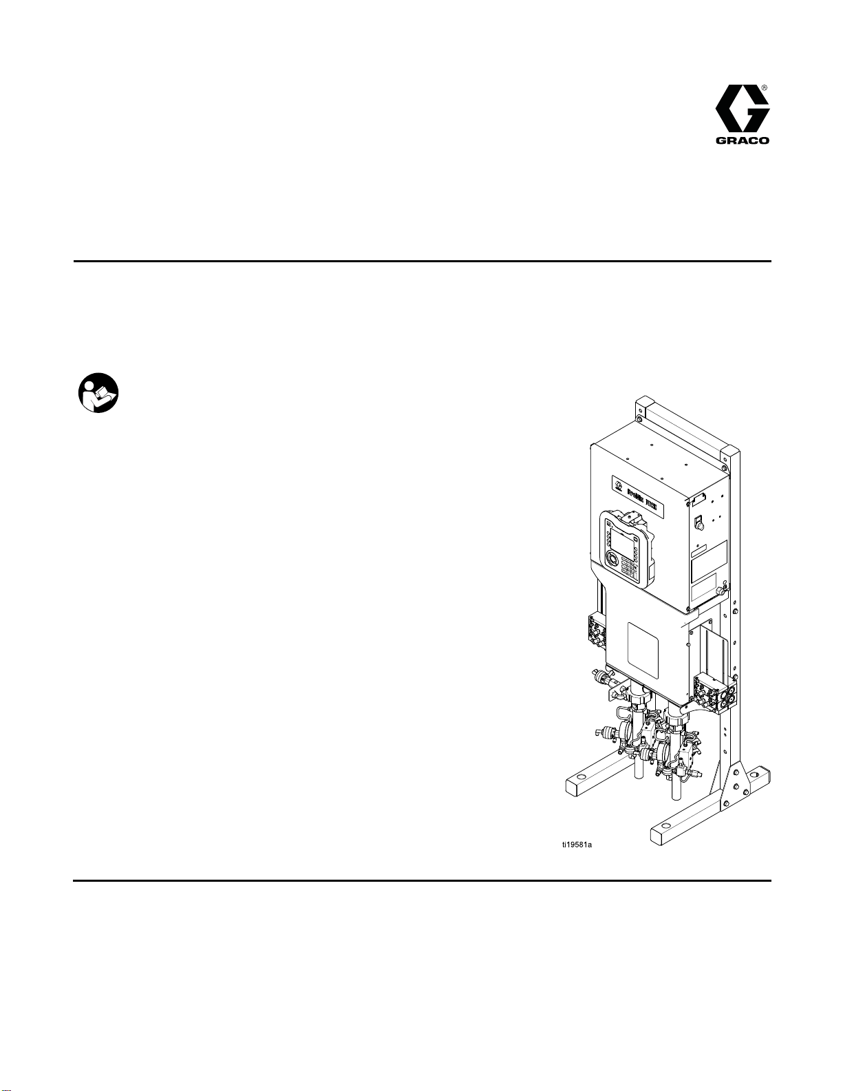
Operation
ProMix® PD2K El
ectronic
332562B
Proportioner
Positive displacement proportioning of 2-component materials helps reduce waste. Manual system with
Advanced Display Module. For professional use only.
Important Safety Instructions
Read all warnings and instructions in this manual and in your PD2K
Installation and Repair/Parts manuals.
Save these instructions.
See page 3
approvals information.
for model part numbers and
EN
PROVEN QUALITY. LEADING TECHNOLOGY.
Page 2

Contents
Models............................................................... 3
Related Manuals ................................................ 6
Warnings ........................................................... 7
Important Isocyanate (ISO) Information................ 10
Glossary of Terms .............................................. 12
Overview............................................................ 13
Usage ......................................................... 13
Component Identification and
Definition........................................ 13
Advanced Display Module................................... 16
ADM Display................................................ 16
USB Download Procedure............................ 16
USB Upload Procedure ................................ 17
ADM Keys and Indicators ............................. 18
Soft Key Icons ............................................. 19
Navigating the Screens ................................ 21
Screen Icons ............................................... 21
Booth Control ..................................................... 22
Booth Control Display................................... 22
Booth Control Keys and Indicators ................ 23
Operation........................................................... 24
Pre-operation Checklist ................................ 24
Flush Before Using Equipment...................... 24
Power On .................................................... 24
Initial System Setup ..................................... 25
Prime and Fill the System............................. 25
Spraying...................................................... 26
Purging ....................................................... 27
Pressure Relief Procedure............................ 29
Valve Settings..............................................30
Shutdown.................................................... 30
Run Mode Screens............................................. 31
Splash Screen ............................................. 31
Home Screen .............................................. 31
Spray Screen............................................... 34
Fill Screen................................................... 35
Usage Screen.............................................. 36
Jobs Screen ................................................ 37
Errors Screen .............................................. 37
Events Screen ............................................. 37
Setup Mode Screens .......................................... 38
Password Screen......................................... 38
System Screen 1 ......................................... 39
System Screen 2 ......................................... 40
System Screen 3 ......................................... 42
Information for Systems with Multiple
Guns..............................................43
System Screen 4 ......................................... 44
Recipe Screen............................................. 45
Flush Screen ............................................... 47
Pump Screen 1............................................ 48
Pump Screen 2............................................ 49
Pump Screen 3............................................ 50
Calibrate Screen 1 ....................................... 51
Calibrate Screen 2 ....................................... 51
Calibrate Screen 3 ....................................... 52
Maintenance Screen 1 ................................. 53
Maintenance Screen 2 ................................. 53
Maintenance Screen 3 ................................. 53
Maintenance Screen 4 ................................. 54
Advanced Screen 1...................................... 55
Advanced Screen 2...................................... 56
Advanced Screen 3...................................... 56
Advanced Screen 4...................................... 56
ation Checks.............................................. 57
Calibr
Pump Pr
Pump Vo
Solven
Color Change.....................................................60
Single Color Systems................................... 60
Multiple Color Systems................................. 60
System Errors ....................................................61
tenance ...................................................... 74
Main
Prev
Flus
Clea
Technical Data ...................................................75
Graco Standard Warranty.................................... 76
essure Check ................................. 57
lume Check.................................... 58
t Meter Calibration ............................. 59
entive Maintenance Schedule ................ 74
hing ...................................................... 74
ning the ADM........................................ 74
2
332562B
Page 3
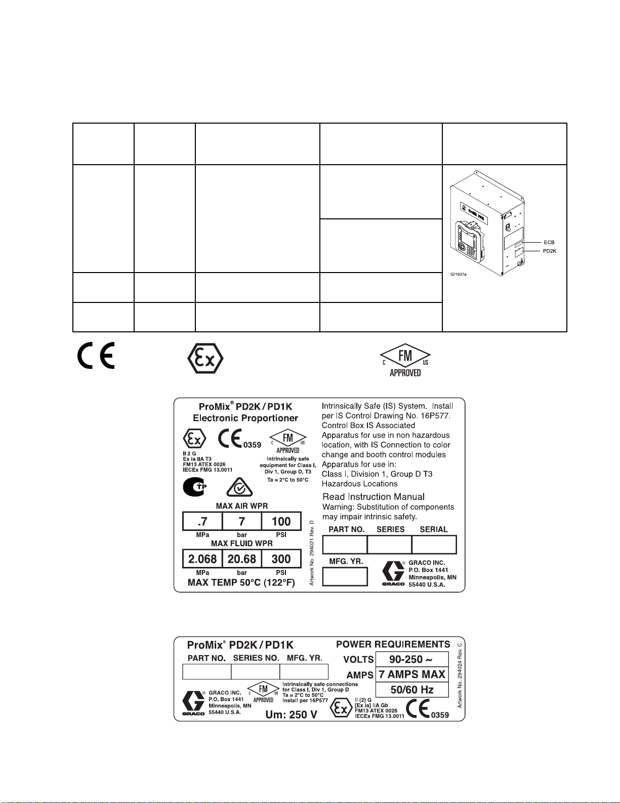
Models
See Figs. 1–7 for component identification labels, including approval information and certification.
Models
Part No.
MC0500
MC1000
MC2000
0359
Series
A
A
A
Maximum Air Working
Pressure
100 psi (0.7 MPa, 7.0 bar)
100 psi (0
100 psi (0.7 MPa, 7.0 bar) 1500 psi (10.34 MPa,
.7 MPa, 7.0 bar)
II 2 G
Maximum Fluid Working
Pressure
With low-
pressure pum
300 psi (2.0
20.68 bar)
With high-
pressure pumps:
1500 psi (10.34 MPa,
103.4 bar)
300 psi (2
20.68 bar
103.4 bar)
ps:
68 MPa,
.068 MPa,
)
Location of PD2K and
Electrical Control Box
(ECB) Labels
Figure 1 Model MC1000 (Low Pressure) Identification
Label
Figure 2 24M672 Control Box Identification Label
Continued on the next page.
332562B 3
Page 4
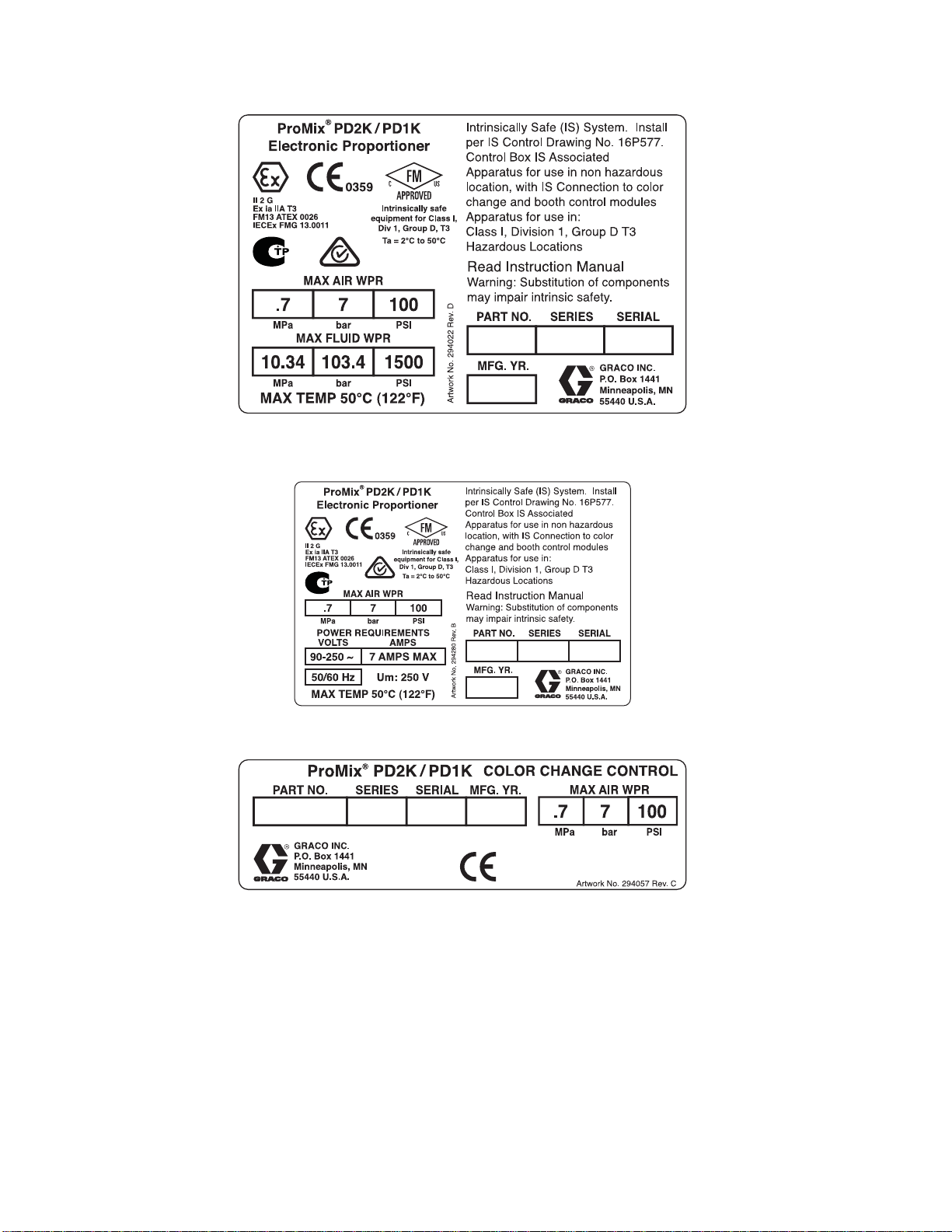
Models
Figure 3 Model MC2000 (High Pressure)
Identification Label
Figure 4 Model MC0500 Identification Label
Figure 5 Non-Intrinsically Safe Color Change Control
(Accessory) Identification Label
4
332562B
Page 5
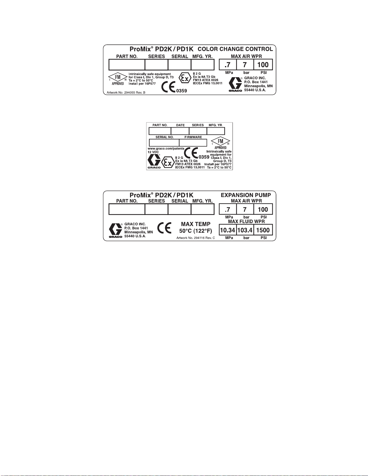
Figure 6 Intrinsically Safe Color Change Control
(Accessory) Identification Label
Figure 7 Booth Control Identification Label
Models
Figure 8 Pump Expansion Kit (Accessory)
Identification Label
332562B 5
Page 6
Related Manuals
Related Manuals
Manual No. Description
3A2800 PD2K Proporti
Manual, Manua
332457 PD2K Proportioner Installation
Manual, Manual Systems
3A2801
332339 Pump Repair-Parts Manual
332454
Mix Manifol
Manual
Color Chan
Manual
oner Repair-Parts
lSystems
d Instructions-Parts
ge Valve Repair-Parts
Manual No. Description
332455
332456 3rd and 4th Pump Kits
334512 PD1K Pump Ex
Color Change Kits InstructionsParts Manual
Instructions-Parts Manual
pansion Kits
Instructio
ns-Parts Manual
6 332562B
Page 7
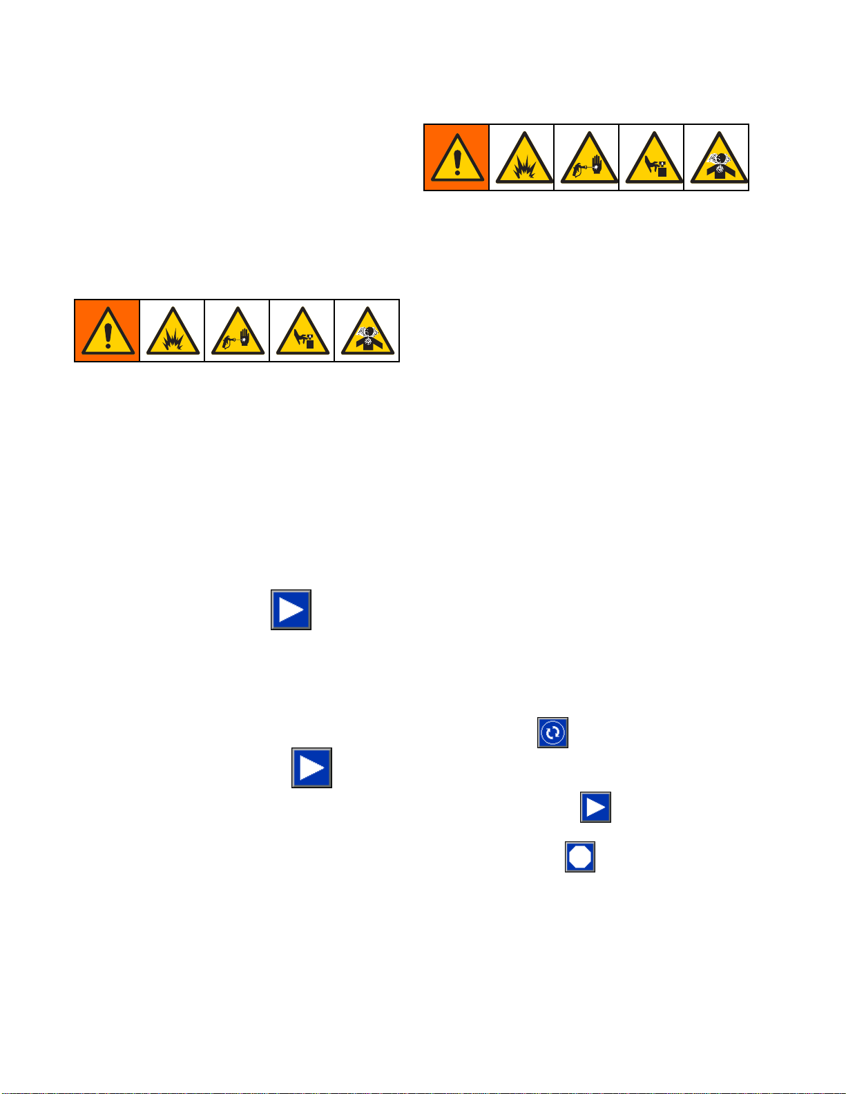
Warnings
Warnings
The following
exclamation p
risks. When th
Warnings. Pr
the body of th
warnings are for the setup, use, grounding, maintenance and repair of this equipment. The
oint symbol alerts you to a general warning and the hazard symbol refers to procedure-specific
ese symbols appear in the body of this manual or on warning labels, refer backtothese
oduct-specific hazard symbols and warnings not covered in this section may appear throughout
is manual where applicable.
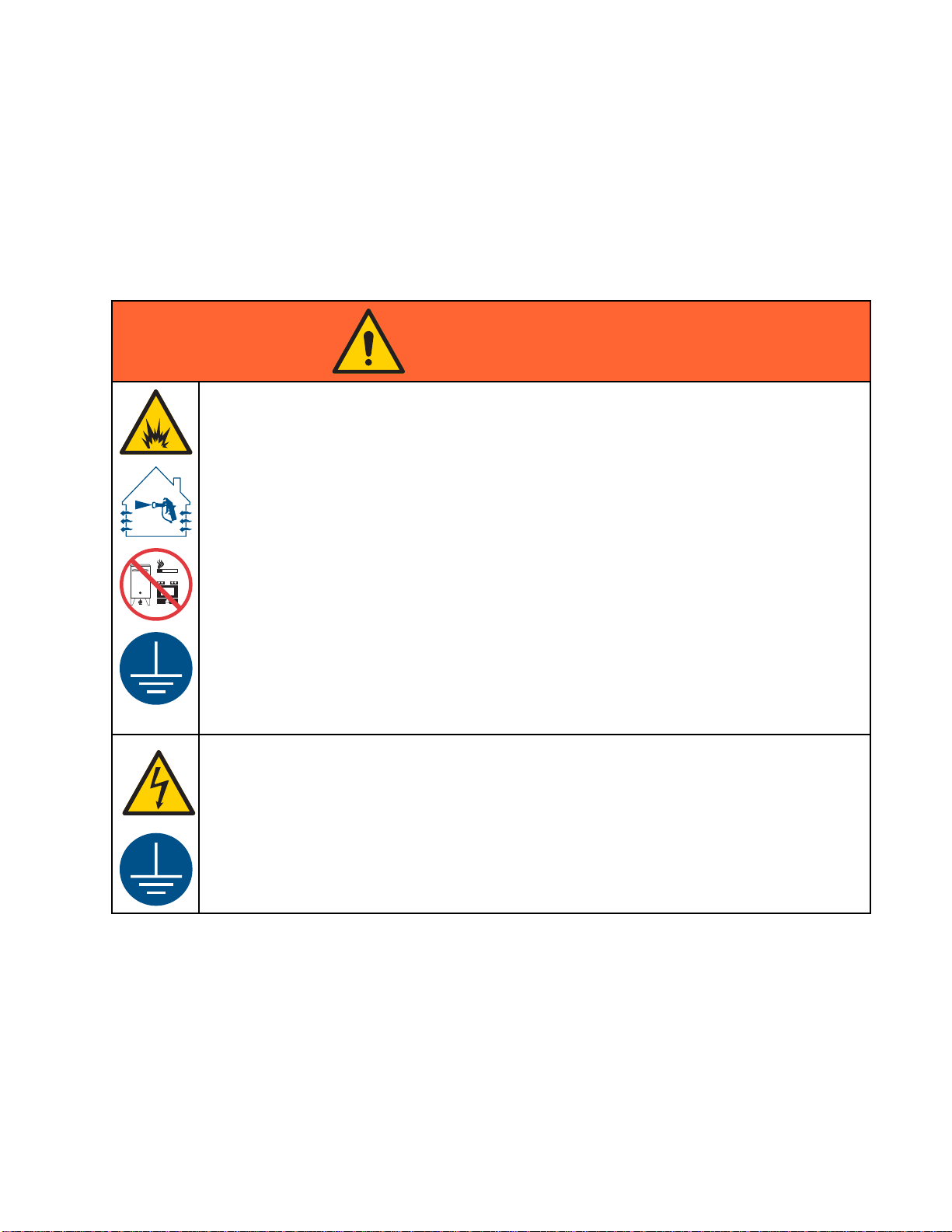
WARNING
FIRE AND EX
Flammable fumes, such as solvent and paint fumes, in work area can ignite or explode. To help
prevent fire and explosion:
• Use equipment only in well ventilated area.
• Eliminate all ignition sources; such as pilot lights, cigarettes, portable electric lamps, and
plastic drop cloths (potential static arc).
•Keepwork
• Do not plug or unplug power cords, or turn power or light switches on or off when flammable
fumes are present.
• Ground all equipment in the work area. See Grounding instructions.
•Useonly
• Hold gun firmly to side of grounded pail when triggering into pail. Do not use pail liners unless
they are antistatic or conductive.
• Stop operation immediately if static sparking occurs or you feel a shock, Do not use
equipment until you identify and correct the problem.
• Keepaw
PLOSION HAZARD
area free of debris, including solvent, rags and gasoline.
grounded hoses.
orking fire extinguisher in the work area.
332562B
ELECTRIC SHOCK HAZARD
This equipment must be grounded. Improper grounding, setup, or usage of the system can
cause electric shock.
•Turn
• Connect only to grounded power source.
• All electrical wiring must be done by a qualified electrician and comply with all local codes
off and disconnect power at main switch before disconnecting any cables and before
icing or installing equipment.
serv
and regulations.
7
Page 8
Warnings
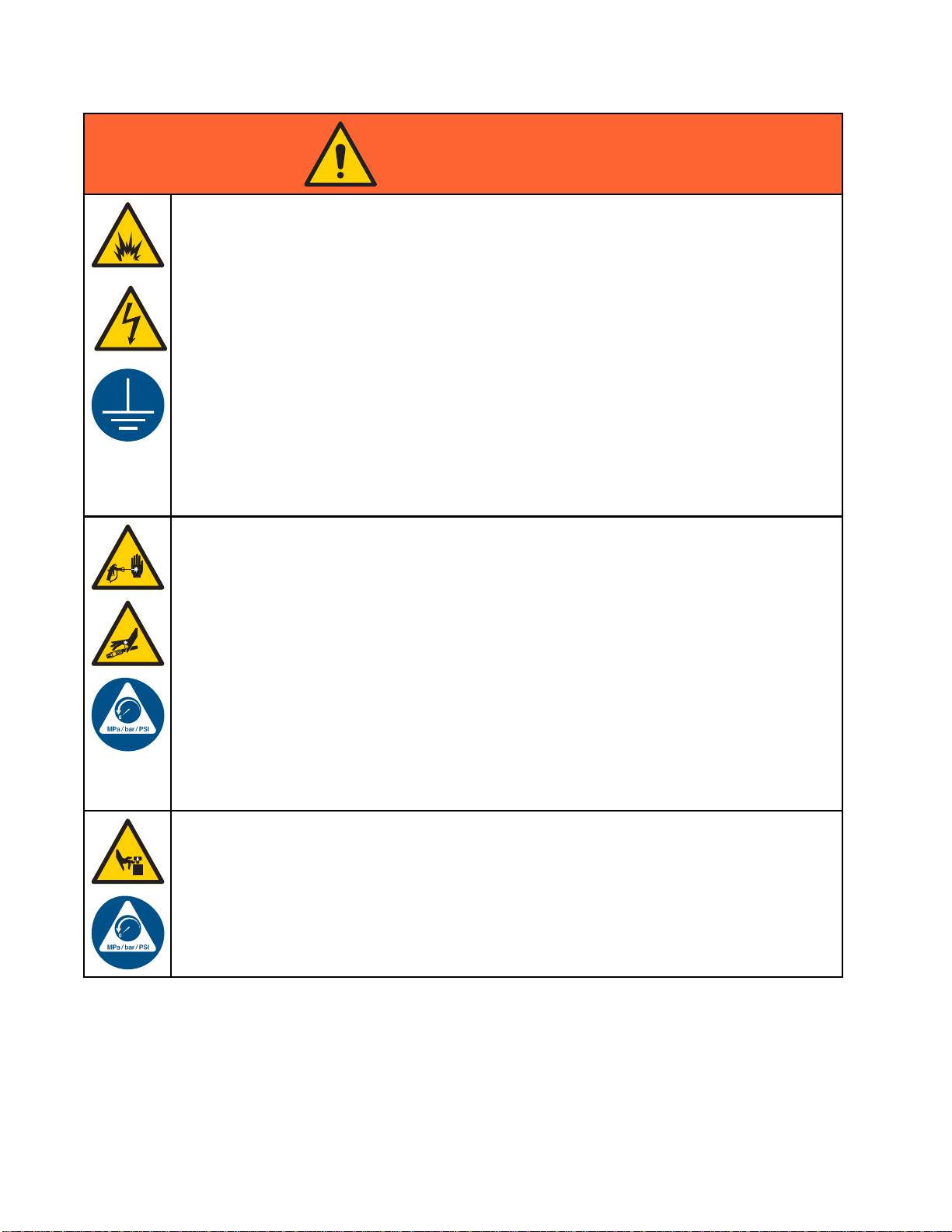
WARNING
INTRINSIC SAFETY
Intrinsical
equipment wi
Follow local
• Be sure your installation complies with national, state, and local codes for the installation of
electrical apparatus in a Class I, Group D, Division 1 (North America) or Class I, Zones 1
and 2 (Europe) Hazardous Location, including all of the local safety fire codes (for example,
NFPA 33, NEC 500 and 516, OSHA 1910.107, etc.).
•Tohelpprev
• Equipment
Safety. T
unit from
SKIN INJECTION HAZARD
High-pr
look lik
treatme
• Do not spray without tip guard and trigger guard installed.
• Engage
• Do not point gun at anyone or at any part of the body.
• Do not put your hand over the spray tip.
• Do not s
• Follow the Pressure Relief Procedure when you stop spraying/dispensing and before
cleaning, checking, or servicing equipment.
• Tighten all fluid connections before operating the equipment.
•Check
ly safe equipment that is installed improperly or connected to non-intrinsically safe
ll create a hazardous condition and can cause fire, explosion, or electric shock.
regulations and the following safety requirements.
ent fire and explosion:
• Do not install equipment approved only for a non-hazardous location in a hazardous
location. See model ID label for the intrinsic safety rating of your model.
• Do not substitute system components as this may impair intrinsic safety.
that comes in contact with the intrinsically safe terminals must be rated for Intrinsic
his includes DC voltage meters, ohmmeters, cables, and connections. Remove the
the hazardous area when troubleshooting.
essure fluid from gun, hose leaks, or ruptured components will pierce skin. This may
e just a cut, but it is a serious injury that can result in amputation. Get immediate surgical
nt.
trigger lock when not spraying.
top or deflect leaks with your hand, body, glove, or rag.
hoses and couplings daily. Replace worn or damaged parts immediately.
MOVING PARTS HAZARD
Moving parts can pinch, cut or amputate fingers and other body parts.
•Keep
• Do not operate equipment with protective guards or covers removed.
• Pressurized equipment can start without warning. Before checking, moving, or servicing
clear of moving parts.
equipment, follow the Pressure Relief Procedure and disconnect all power sources.
8 332562B
Page 9
Warnings
WARNING
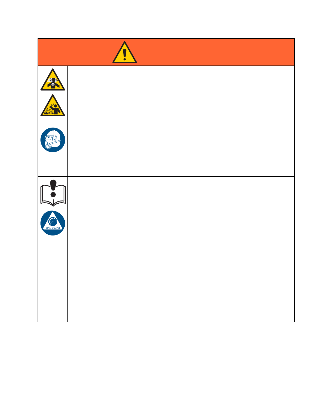
TOXIC FLUID OR FUMES
Toxic fluids or fumes can cause serious injury or death if splashed in the eyesoronskin,
inhaled, or swallowed.
• Read MSDSs to
• Store hazardous fluid in approved containers, and dispose of it according to applicable
guidelines.
• Always wear chemically impermeable gloves when spraying, dispensing, or cleaning
equipment.
PERSONAL P
Wear appro
including
equipment
• Protective eyewear, and hearing protection.
• Respirat
manufact
EQUIPMENT MISUSE HAZARD
Misuse can cause death or serious injury.
• Do not op
• Do not exceed the maximum working pressure or temperature rating of the lowest rated
system component. See Technical Data in all equipment manuals.
• Use fluids and solvents that are compatible with equipment wetted parts. See Technical Data
in all equipment manuals. Read fluid and solvent manufacturer’s warnings. For complete
information about your material, request MSDS from distributor or retailer.
• Do not
• Turn off all equipment and follow the Pressure Relief Procedure when equipment is not in use.
• Check equipment daily. Repair or replace worn or damaged parts immediately with genuine
manufacturer’s replacement parts only.
• Do not
and c
• Make sure all equipment is rated and approved for the environment in which youareusingit.
• Use equipment only for its intended purpose. Call your distributor for information.
• Rout
• Do not kink or over bend hoses or use hoses to pull equipment.
• Keep children and animals away from work area.
•Com
priate protective equipment when in the work area to help prevent serious injury,
eye injury, hearing loss, inhalation of toxic fumes, and burns. This protective
includes but is not limited to:
ors, protective clothing, and gloves as recommended by the fluid and solvent
urer.
erate the unit when fatigued or under the influence of drugs or alcohol.
leave the work area while equipment is energized or under pressure.
alter or modify equipment. Alterations or modifications may void agency approvals
reate safety hazards.
e hoses and cables away from traffic areas, sharp edges, moving parts, and hot surfaces.
ply with all applicable safety regulations.
know the specific hazards of the fluids you are using.
ROTECTIVE EQUIPMENT
332562B 9
Page 10
Important Isocy
anate (ISO) Information
Important Iso
Isocyanates (ISO) are catalysts used in two
component materials.
cyanate (ISO) Information
Isocyanate Conditions
Spraying or dispensing materials containing
isocyanates creates potentially harmful mists,
vapors, and atomized particulates.
Read material manufacturer’s warnings and
material MSDS to know specific hazards and
precautions related to isocyanates.
Prevent inhalation of isocyanate mists, vapors,
and atomized particulates by providing sufficient
ventilation in the work area. If sufficient ventilation
is not available, a supplied-air respirator is required
foreveryoneintheworkarea.
To prevent contact with isocyanates, appropriate
personal protective equipment, including
chemically impermeable gloves, boots, aprons,
and goggles, is also required for everyone in the
work area.
Keep Components A and B Separate
Cross-contamination can result in cured
material in fluid lines which could cause serious
injury or damage equipment. To prevent
cross-contamination:
• Never inte
Bwettedpa
• Never use s
contamina
rchange component A and component
rts.
olvent on one side if it has been
ted from the other side.
Moisture Sensitivity of Isocyanates
Exposure
ISO to pa
crystal
Eventua
will beg
to moisture (such as humidity) will cause
rtially cure; forming small, hard, abrasive
s, which become suspended in the fluid.
lly a film will form on the surface and the ISO
in to gel, increasing in viscosity.
NOTICE
Partially cured ISO will reduce performance and
the life of all wetted parts.
Material Self-ignition
Some materials may become self-igniting if applied
too thick. Read material manufacturer’s warnings
and material MSDS.
• Always use a sealed container with a desiccant
dryer in the vent, or a nitrogen atmosphere.
Never store ISO in an open container.
• Keep the ISO pump wet cup or reservoir (if
installed) filled with appropriate lubricant. The
lubricant creates a barrier between the ISO and
the atmosphere.
• Use only moisture-proof hoses compatible with
ISO.
• Never use reclaimed solvents, which may
contain moisture. Always keep solvent
containers closed when not in use.
• Always lubricate threaded parts with an
appropriate lubricant when reassembling.
NOTE: The amount of film formation and rate of
crystallization varies depending on the blend of ISO,
the humidity, and the temperature.
10 332562B
Page 11

Important Isocy
anate (ISO) Information
Changing Mate
rials
NOTICE
Changing the material types used in your
equipment requires special attention to avoid
equipment damage and downtime.
• When changi
multiple ti
• Always clea
flushing.
• Check with
chemical c
• When chang
or polyur
componen
have amin
often hav
ng materials, flush the equipment
mes to ensure it is thoroughly clean.
n the fluid inlet strainers after
your material manufacturer for
ompatibility.
ing between epoxies and urethanes
eas, disassemble and clean all fluid
ts and change hoses. Epoxies often
es on the B (hardener) side. Polyureas
eaminesontheA(resin)side.
332562B
11
Page 12

Glossary of Term
s
Glossary of Te
Advanced Display Module (ADM) -the
user interface for the system. See
Advanced Display Module, page 16.
Enhanced Flu
controller f
Grand Total - a non-resettable value that shows
the total amount of material dispensed through the
system.
Idle - if the gun is not triggered for a user-settable
value, the system enters Idle mode. Trigger the gun
to resume operation.
Intrinsic
certain co
Job Total - a resettable value that shows the amount
of material dispensed through the system for one job.
A job is complete when the user presses the Job
Complete key on the Booth Control or ADM.
Mix - when cross-linking of the resin (A) and catalyst
(B) occurs.
id Control Module (EFCM) -thefluid
or the system.
ally Safe (IS) - refers to the ability to locate
mponents in a hazardous location.
rms
Potlife Time - the amount of time before a material
becomes unsprayable.
Potlife Volume - the amount of material that is
required to move through the mix manifold, hose, and
applicator before the potlife timer is reset.
Pump Calibration Factor - the amount of material
dispensed per revolution of the motor.
Purge - when all mixed material is flushed from the
mix manifold, hose, and gun.
Purge Time - the amount of time required to flush all
mixed material from the gun.
Run Screens - The Run screens provide a graphical
depiction of system operation and current status.
See RunModeScreens,page31.
Setup Screens - The Setup screens allow the
user to define the system, setup recipes, and
establish system operating parameters. See
Setup Mode Screens, page 38.
Standby - refers to the status of the system.
2
1
332562B
Page 13

Overview
Usage
Overview
This electronic two-component paint proportioner
can blend most two-component paints, including
quick-setting paints (those with a pot life of 5 minutes
and greater).
• The system d
flow, and con
ispenses Material A, monitors fluid
tinually dispenses Material B at ratio.
Component Identification and Definition
Component
Electric
al Control Box
Descripti
• Enhanced
•24VPower
•48VPowe
• Solenoi
•AirFlow
•Relay
•Option
•PumpCo
•CANIso
on
Fluid Control Module (EFCM)
Supply for the barrier board and the EFCM
r Supply for pump motors
d Valves for solvent valve and gun flush box (if present)
Switch
al Pressure Switch for gun flush box (if present)
ntrol Modules (2), one for each pump
lation Board
• Can proportion at ratios from 0.1:1 to 50.0:1
(depending on material, flow rate, pump size
selection, and mix point).
• Will display the last 200 jobs, 200 errors, and 200
events with date, time, and description.
nsically Safe Power Barrier Board
•Intri
Fluid Components • Mix manifold (accessory), which can be attached to the operator’s belt.
• Color/catalyst valve stacks, including pneumatically operated valves for
Material A and B, as well as solvent valves.
• Solvent Flow Switch
• Pumps
• Pressure transducers
anced Display Module
Adv
oth Control
Bo
Use to set up, display, operate, and monitor the system. Use for daily
painting functions including choosing recipes, reading/clearing errors,
and placing the system in Spray, Standby, or Purge mode. Locate in the
non-hazardous area.
e for daily painting functions including choosing recipes,
Us
ading/clearing errors, and placing the system in Spray, Standby, or
re
urge mode. Locate in the hazardous area.
P
332562B 13
Page 14
Overview
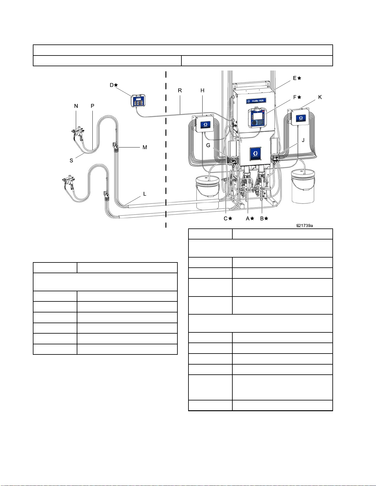
Typical Installation (MC1000, MC2000)
HAZARDOUS (CL
Figure 9
ASSIFIED) LOCATION
NON-HAZARDOU
Component
SLOCATIONONLY
Description
Component
★ Components A through F are included with the
base unit.
A★
B★
C★ Solvent Valve
D★
E★
F★ Advanced Display Module
Description
Material A (Color) Pump
Material B (Catalyst) Pump
Booth Control
Electrical Control Box
Components G through K are included in optional
color change kits.
G Color Change Valves (accessory)
H
J
K
Components L through S are accessories and
must be ordered separately.
L
M
N
P
R
S Gun Fluid Hose (accessory)
Color Change Module (accessory)
Catalyst Change Valves
(accessory)
Catalyst Change Module
(accessory)
Fluid/Air hose Bundle (accessory)
Mix Manifold (accessory)
Air Spray Gun (accessory)
Gun Air Hose (accessory)
Intrinsically Safe CAN Cable (to
connect booth control to electrical
control box)
4
1
332562B
Page 15
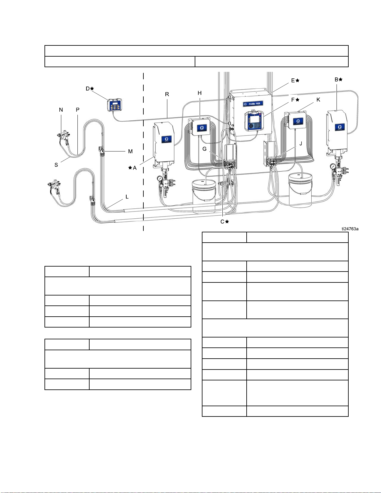
Typical Installation (MC0500)
Overview
HAZARDOUS (CL
Figure 10
ASSIFIED) LOCATION
NON-HAZARDOU
Component
SLOCATIONONLY
Description
Component
★ Components D, E, and F are included with the
base unit.
D★
E★
F★ Advanced Display Module
Component
★ Pumps A and B are required but are sold
separately for system design flexibility.
A★
B★
Description
Booth Control
Electrical Control Box
Description
Material A (Color) Pump
Material B (Catalyst) Pump
Components G through K are included in optional
color change kits.
G Color Change Valves (accessory)
H
J
K
Components L through S are accessories and
must be ordered separately.
L
M
N
P
R
S Gun Fluid Hose (accessory)
Color Change Module (accessory)
Catalyst Change Valves
(accessory)
Catalyst Change Module
(accessory)
Fluid/Air hose Bundle (accessory)
Mix Manifold (accessory)
Air Spray Gun (accessory)
Gun Air Hose (accessory)
Intrinsically Safe CAN Cable (to
connect booth control to electrical
control box)
332562B 15
Page 16
Advanced Displa
yModule
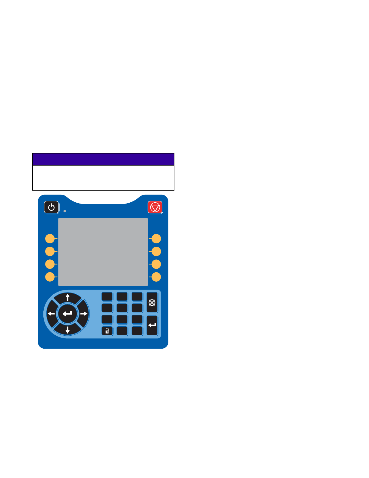
Advanced Display Module
ADM Display
The ADM displ
information
For detail on the display and individual
screens, see Run Mode Screens, page 31,or
Setup Mode Screens, page 38.
Keys are used to input numerical data, enter setup
screens, navigate within a screen, scroll through
screens, and select setup values.
ay shows graphical and text
related to setup and spray operations.
NOTICE
To preven
press the
plastic c
t damage to the softkey buttons, do not
buttons with sharp objects such as pens,
ards, or fingernails.
USB Download Procedure
Use the USB po
data.
1. Enable USB downloads. See
Advanced Screen 3, page 56.
2. Remove the cover from the USB port on the
bottom of the ADM. Insert the USB drive.
3. During the download, USB BUSY appears on the
screen.
4. When the download is complete, USB IDLE
appears on the screen. The USB drive may then
be removed.
NOTE: If the download operation takes longer
than 60 seconds, the message disappears. To
determine if the USB is busy or idle, check the
Error Status bar on the screen. If idle, remove
the USB.
5. Insert the USB flash drive into the USB port of
the computer.
6. The USB flash drive window automatically opens.
If it does not, open the USB flash drive from
within Windows® Explorer.
rt on the ADM to download or upload
1 2 3
4 5 6
7 8 9
ure 11 Advanced Display Module
Fig
0 .
7. Open Graco folder.
8. Open system folder. If downloading data from
more than one system, there will be more than
one folder. Each folder is labeled with the
corresponding serial number of the ADM. (The
serial number is on the back of the ADM.)
9. Open DOWNLOAD folder.
10. Open LOG FILES folder labeled with the highest
number. The highest number indicates the most
recent data download.
11. Open log file. Log files open in Microsoft®
Excel® by default if the program is installed.
They also can be opened in any text editor of
Microsoft® Word.
NOTE: All USB logs are saved in Unicode
(UTF-16) format. If opening the log file in
Microsoft Word, select Unicode encoding.
12. Always reinstall the USB cover after removing
the USB, to keep the drive free of dirt and dust.
16 332562B
Page 17

Advanced Displa
yModule
USB Upload Pro
Use this procedure to install a system configuration
file and/or a custom language file.
1. If necessary
Procedure, t
folder struc
2. Insert the US
the compute
3. The USB flash
If it does no
within Win
4. Open the Gr
5. Open the sy
than one sy
folder wi
labeled w
the ADM. (
the modul
o automatically generate the proper
ture on the USB flash drive.
t, open the USB flash drive from
dows Explorer.
stem folder. If working with more
stem, there will be more than one
thin the Graco folder. Each folder is
ith the corresponding serial number of
The serial number is on the back of
e.)
cedure
, follow the USB Download
B flash drive into the USB port of
r.
drive window automatically opens.
aco folder.
6. If installing the system configuration settings file,
place SETTINGS.TXT file into UPLOAD folder.
7. If installing the custom language file, place
DISPTEXT.TXT file into UPLOAD folder.
8. Remove the USB flash drive from the computer.
9. Install the USB flash drive into the USB port of
the ProMix PD2K system USB port.
10. During the upload, USB BUSY displays on the
screen.
11. Remove the USB flash drive from the USB port.
NOTE: If the custom language file was installed,
users can now select the new language from the
Language drop-down menu in the Advanced Setup
Screen 1.
332562B
17
Page 18
Advanced Displa
yModule
ADM Keys and Indicators
NOTICE
To prevent dam
press the butt
plastic card
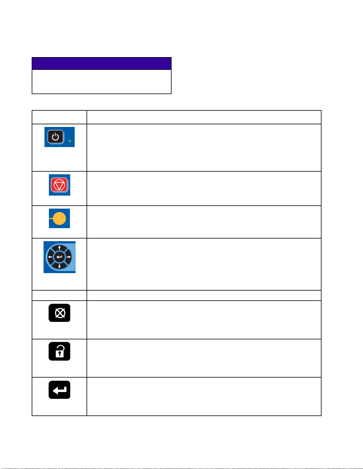
Table 1 : ADM Keys and Indicators
Key Function
Startup/Shutdown
Key and Indicator
Stop
Soft Key
age to the softkey buttons, do not
ons with sharp objects such as pens,
s, or fingernails.
Press to startup or shutdown the pump/motor.
• Solid green indicates that power is applied to the motor.
• Solid yellow indicates that power to the motor is off.
• Blinking green or yellow indicates that the system is in Setup mode.
Press to immediately stop the system and remove motor power.
Press to select the specific screen or operation shown on the display directly next to
each key. The top left soft key is the Edit key, which allows access to any settable
fields on a screen.
s
•
Left/Right Arrows:
Use to move from screen to screen.
Navigation Keys
Numeric Keypad
el
Canc
up
Set
ter
En
Up/Down Arrows:
•
menu, or multiple screens within a function.
Use to
Use to cancel a data entry field.
Press to enter or exit Setup mode.
Press to choose a field to update, to make a selection, to save a selection or value, to
enter a screen, or to acknowledge an event.
input values. See ADM Display, page 16.
Use to move among fields on a screen, items on a dropdown
18 332562B
Page 19
Soft Key Icons
Advanced Displa
yModule
The following icons appear in the ADM display,
directly to the left or right of the soft key which
activates that operation.
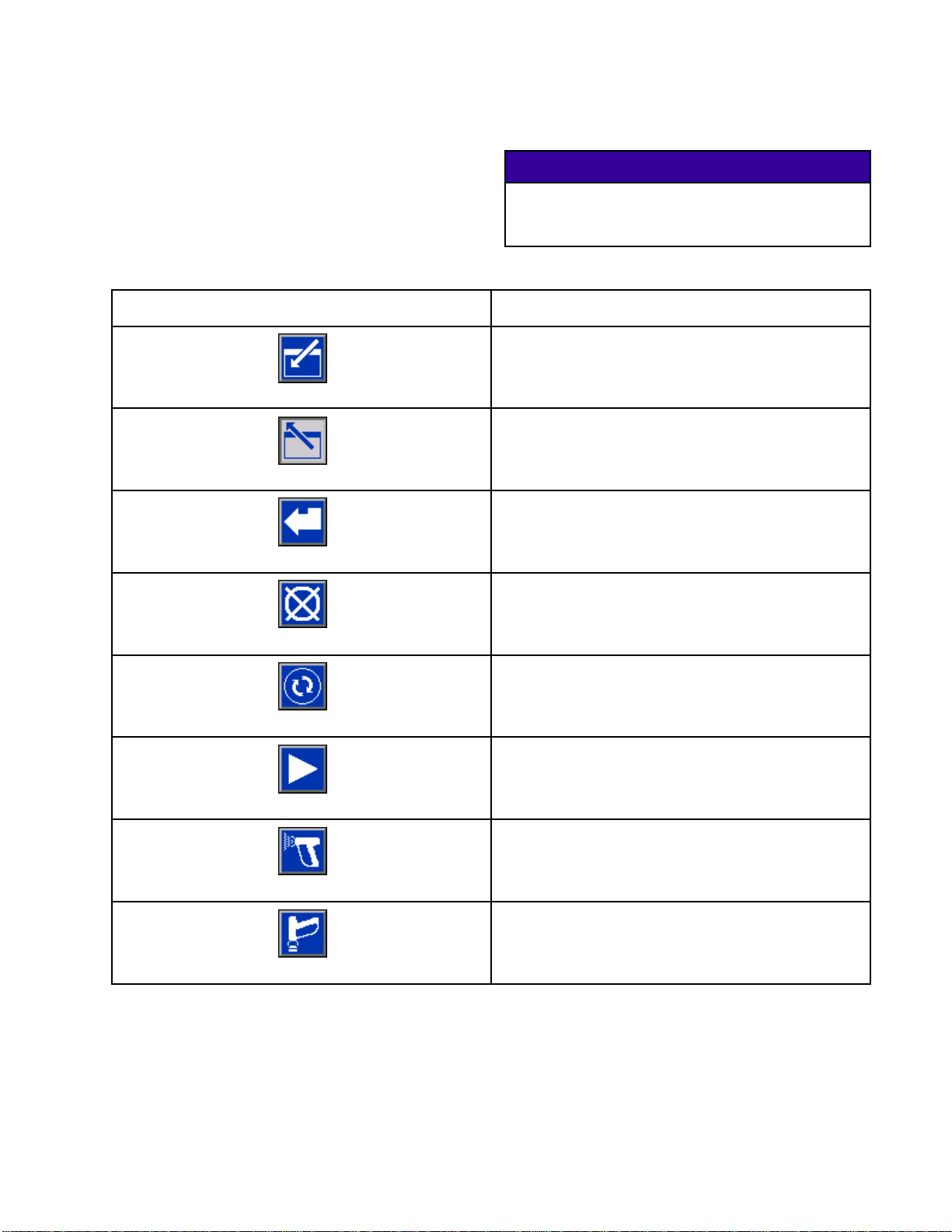
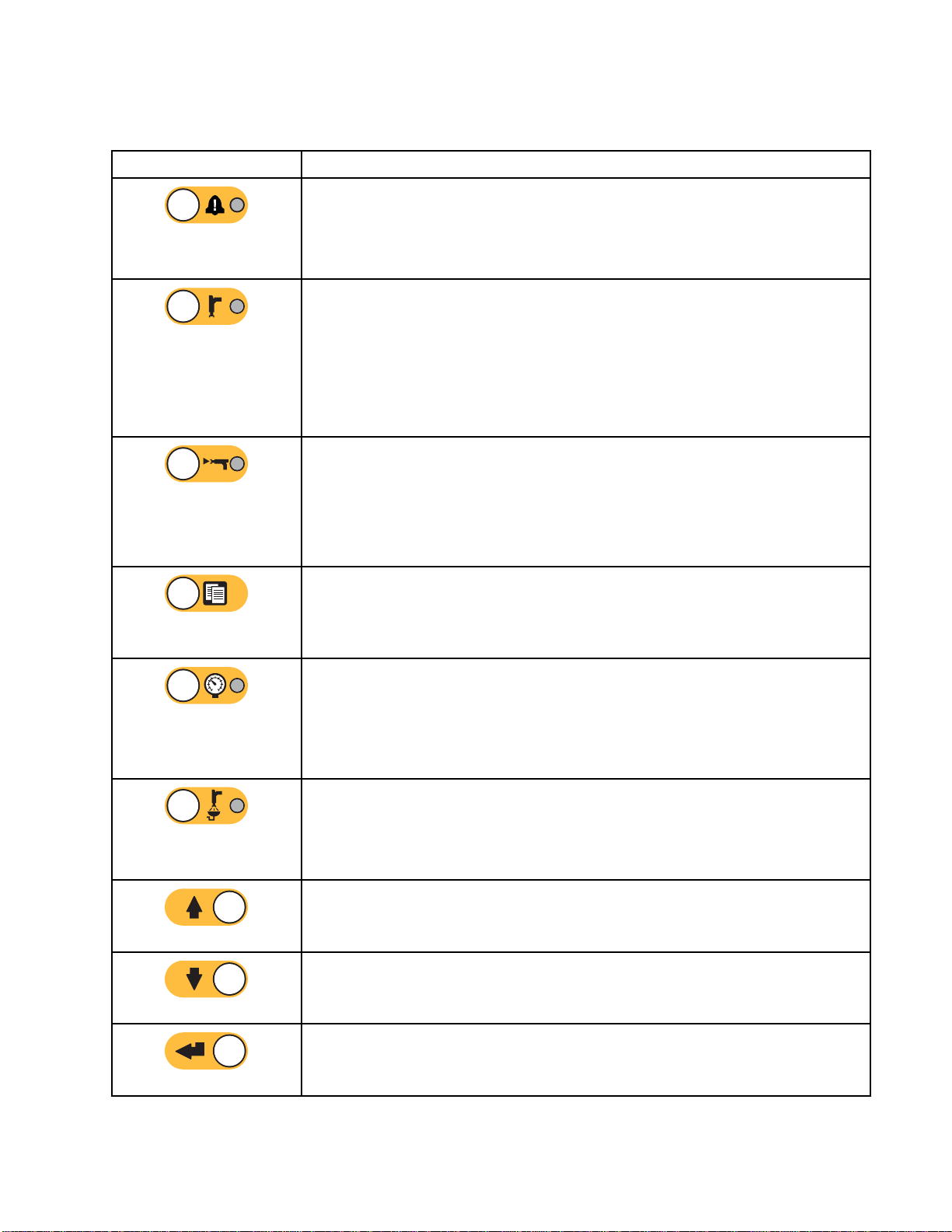
Table 2 : Soft Key Functions
Key Function
Enter Screen
Exit Screen
Accept
To prevent damage to the softkey buttons, do not
press the buttons with sharp objects such as pens,
plastic cards, or fingernails.
Press to enter screen for editing. Highlights editable
data on a screen. Use Up/Down arrows to move
between data fields on the screen.
Press to ex
Press to accept calibration value.
Press to cancel or reject calibration value.
NOTICE
it screen after editing.
Cancel
Prime Pump
Line/Fill/Run
Mix
Purge
Press to start a pump priming procedure.
Press to start a line fill procedure.
Press to start a spray procedure.
Press to start a gun purge procedure.
332562B 19
Page 20

Advanced Displa
Key Function
yModule
Standby
Stop
Pressure Check
Volume Check
Job Complete
Counter Reset
Press to stop all pumps and put system in Standby.
Presstostartapumppressurecheck.
Press to st
Press to log the material usage and increment the
job number.
Press to reset the current usage counter.
Appears on the User ID Keyboard screen. Use to
move cursor to the left.
art a pump volume check.
Move Cu
Move Cursor to Right
Upper Case/Lower Case
rsor to Left
Erase All
Backspace
Appears on the User ID Keyboard screen. Use to
move cursor to the right.
Appears on the User ID Keyboard screen. Use to
erase all characters.
ears on the User ID Keyboard screen. Use to
App
se one character at a time.
era
Appears on the User ID Keyboard screen. Use to
change case (upper/lower).
20 332562B
Page 21
Advanced Displa
yModule
Navigating th
There are two sets of screens:
• The Run screen
display syst
• The Setup scr
advanced fea
Press
screens. If the system has a password lock, the
Password screen displays. If the system is not locked
(password is set to 0000), System Screen 1 displays.
Press
Home screen.
Press the Enter soft key
function on any screen.
Press the Exit soft key
e Screens
s control mixing operations and
em status and data.
eens control system parameters and
tures.
on any Run screen to enter the Setup
on any Setup screen to return to the
to activate the editing
to exit any screen.
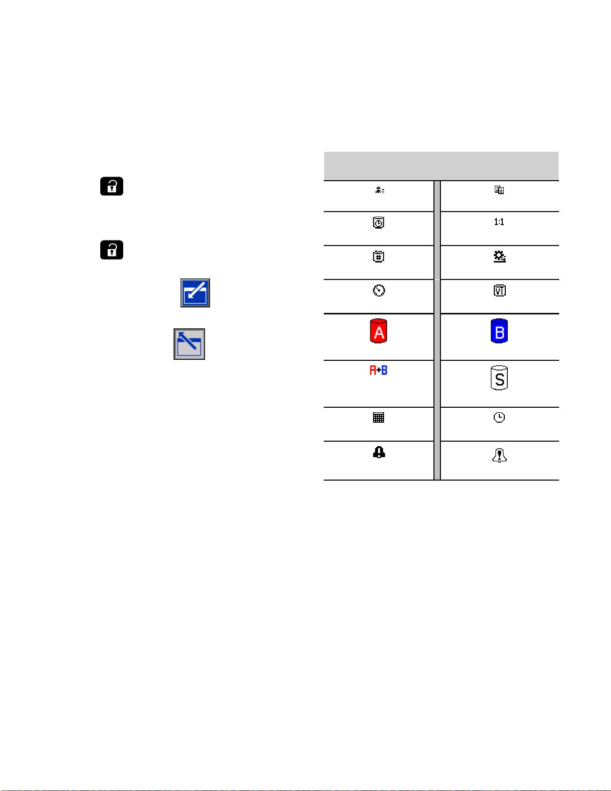
Screen Icons
As you move through the screens, you will notice
that icons are used frequently to simplify global
communication. The following descriptions explain
what each icon represents.
Screen Icons
User ID Job Number
Potlife Target Rati
Recipe Number Flow Rate
Pressure Volume
Material A Material B
o
Use the other softkeys to select the function adjacent
to them.
Material A+B
Calendar Time
Alarm/Advisory
Solven
Deviation
t
332562B
21
Page 22
Booth Control
Booth Control
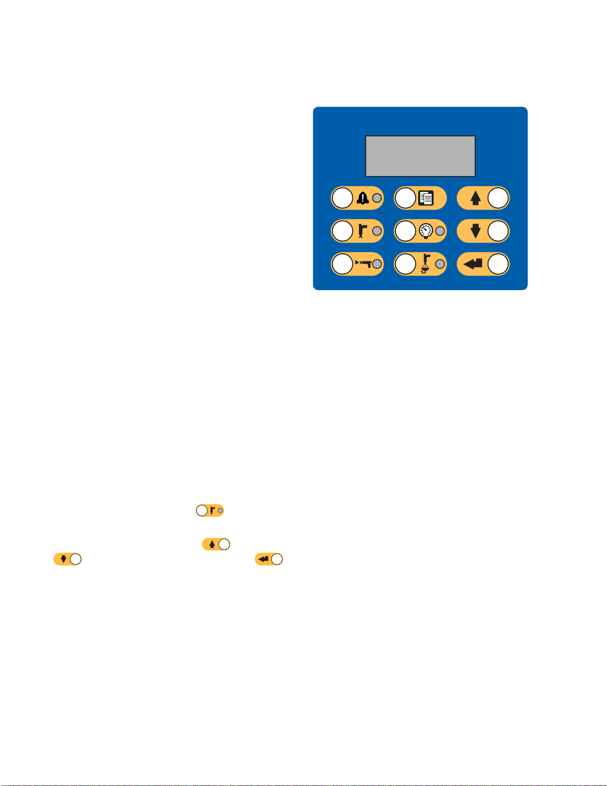
Booth Control
The booth control is the main control device
used by the operator for daily painting functions
including: changing recipes, signaling job complete,
reading/clearing alarms, and placing the system in
Standby, Mix, or Purge mode. It is typically mounted
inside the booth or near the painter.
The booth co
formats:
• R-xx (active recipe)
• P-xx (recipe loaded in the pumps)
• G-xx (recipe loaded in the gun)
The booth control display circulates through the
recipe and error status:
•Display
spray (t
same rec
not show
spray. (
•Iftheg
the pum
altern
ntrol displays the recipe in the following
s the recipe number (R-xx) when ready to
he pumps and gun are loaded with the
ipe). If the display is on steady and does
recipe 0 or 61, the system is ready to
Recipe 61 indicates an unknown material.)
un is loaded with one recipe (G-xx) and
ps with another (P-xx), the display will
ate between the two recipes.
Display
Figure 12 Booth Control
•Ifanal
and th
ackno
the LE
will a
Press and hold the Standby key
to turn the pumps on or off.
To select a new recipe, scroll Up
If Enter is not pressed within 5 seconds, the system
will revert to the existing recipe.
arm occurs, the alarm code is displayed
e red Alarm indicator will flash until
wledged. After the alarm is acknowledged,
D will be on steady and the recipe number
lternate with the code.
for 2 seconds
or Down
to the desired recipe, then press Enter .
2
2
332562B
Page 23
Booth Control
Booth Control
Key/Indicator
Alarm Reset K
Indicator
Standby Mode Key
and Indicator
Mix Mode K
Indicat
ey and
or
Keys and Indicators
Definition and Function
• Red LED is soli
• Red LED blink
ey and
any level.
• Press key to a
• Starts Standby mode.
• Green LED remains lit while in Standby mode.
• Green LED blinks when the system is on and is not mixing or purging. In Idle
mode, the Standby LED and the Mix LED both blink.
• Green LED blinks during pump maintenance checks.
• Press and hold the key to startup or shutdown the pumps.
• Starts Mix mode.
• Green LED remains lit while in Mix mode.
• Green LED blinks during a mix fill. If there is no fluid flow for 30 sec after
starting mix fill, the process must be restarted.
• In Idle mode, the Mix LED and the Standby LED both blink.
d when an alarm condition is present.
s when an event requiring user acknowledgement occurs at
cknowledge. LED shuts off after alarm is cleared.
Job Complete Key
Pressure Control Key
and Indicator
ge Mode Key and
Pur
icator
Ind
Up Key
own Key
D
• Signal
•Presst
• Starts Pressure Change mode.
• Green LED blinks while in Pressure Change mode.
• To change the pressure, press the Pressure Control key and use the Up/Down
• Starts Purge mode.
• Green LED remains lit while in Purge mode.
• Green LED blinks when gun needs to be purged and is waiting for purge to
•Sc
•Sc
• Scrolls recipe numbers down.
• Scrolls pressure value down in Pressure Change mode.
s that job is complete, and resets A, B, and solvent totalizers.
o display the current job number on the booth control. Press a second
o log the current job and increment to the next job number. Times out
time t
5 seconds of inactivity.
after
keys to select the desired pressure. Pressure Change mode times out after 5
seconds of inactivity. Stored recipe is only updated at the end of a spray mode.
begin.
rolls recipe numbers up.
rolls pressure value up in Pressure Change mode.
• Enters selected recipe and starts color change sequence.
• Accepts pressure value change.
Enter Key
332562B 23
Page 24

Operation
Operation
Pre-operatio
Go through the Pre-Operation Checklist daily, before
each use.
✔
n Checklist
Checklist
System grou
Verify all grounding connections
were made. See Grounding in the
Installation manual.
All connections tight and correct
Verify all
system co
installe
manual.
Fluid supply containers filled
Check co
solvent
Dose valves set
Check that dose valves are set
1–1/4 turns open. Start with
the settings recommended in
Valve Settings, page 30, then adjust
as needed.
nded
electrical, fluid, air, and
nnections are tight and
d according to the Installation
mponent A and B and
supply containers.
Flush Before U
The pump fluid section was tested with lightweight
oil, which is left in the fluid passages to protect parts.
To avoid contaminating your fluid with oil, flush the
equipment with a compatible solvent before using
the equipment.
sing Equipment
Power On
1. Turn the AC
2. The Graco l
initializ
3. Press the Start key
change from “System Off” to “Startup.” Once
the pumps are powered and are in the Home
position, the system status will change from
“Startup” to “Standby.”
Power Switch ON (I = ON, 0 = OFF).
ogo will display while the system
es, followed by the Home screen.
. The system status will
supply valves open and
Fluid
ure set
press
The recommended component A and
B fluid supply pressures are 1/2 to 2/3
of the target spray pressure.
NOTE: Low pressure systems may
be set within a range of ± 100 psi (0.7
MPa, 7 bar); high pressure systems
may be set within a range of ± 300 psi
(2.1 MPa, 21 bar). If the inlet pressure
is higher than the outlet pressure,
ratio accuracy may be affected.
Solenoid pressure set
85-100 psi inlet air supply (0.6-0.7
MPa, 6-7 bar).
Figure 13 Power Switch
4
2
332562B
Page 25

Operation
Initial Syste
1. Change optional setup selections to
desired parameters, as described in
Setup Mode Screens, page 38.
2. Set recipe and flush information as
described in Recipe Screen, page 45 and
Flush Screen, page 47.
m Setup
Prime and Fill the System
NOTE: See Ru
screen inf
NOTE: Be sure the mix manifold is set to the SPRAY
position.
NOTE: You must prime the input lines to the pumps
or the inputs to the color change valves before
priming the pump and filling the entire system.
n Mode Screens, page 31,forfurther
ormation, if needed.
4. If the system is powered down, press
ADM. Make sure that the system is in Standby
mode.
5. Verify that the recipes and the flush sequences
are programmed correctly by checking
the Recipe Screen, page 45 and the
Flush Screen, page 47.
6. Go to the Fill Screen, page 35.
7. Select the desired color to load. Press the Prime
Pump key
through the color stack and out the outlet stack
dump valve.
NOTE: Inasinglecolorsystem,skipstep7and
prime the pump out to the gun.
8. Press the Fill Line key
the mix manifold. The pump will run until you
press the Stop key
9. Trigger the gun into a grounded metal pail until
. The color will load the pump
to run color out to
to stop the pump.
on the
1. If using an electrostatic gun, shut off the
electrostatics before filling the lines.
2. Adjust the main air pressure. To ensure proper
operation, set the main air pressure as close to
100 psi (0.7 MPa, 7.0 bar) as possible. Do not
use less than 85 psi (0.6 MPa, 6.0 bar).
3. If this is the first time starting up the system, or if
lines may contain air, purge as instructed under
Purging, page 27. The equipment was tested
with lightweight oil, which should be flushed out
to avoid contaminating your material.
the line is full, then press the Stop key
10. Repeat for all material lines.
.
332562B 25
Page 26

Operation
Spraying
To spray in a multiple color system, also see
Multiple Color Systems, page 60.
NOTE: See Run
screen infor
Mode Screens, page 31, for further
mation, if needed.
3. Press Mix
LED will turn on solid to indicate the system is
mixing. Adjust the flow rate by changing the
target pressure. The fluid flow rate shown on the
Spray screen is the combined total of component
A and B out of the gun.
again. The Mix Mode
1. Set the desi
position.
2. Press Mix
correct mixed material volume. The Mix Mode
LED and the recipe display on the booth control
will blink during the mix fill. If the gun is loaded
with one recipe (G-xx) and the pumps with
another (P-xx), the display will alternate between
the two recipes. When the mix fill is completed,
the display will show R-xx, and the system will
go into Standby Mode.
NOTE: The system will automatically run a Mix
Fill if the recipe is not currently loaded into the
system. The Mix Fill volume calculation includes
the mix manifold volume and the mixed material
hose volume. The mixed material hose volume is
determined by the gun hose length and diameter
entered in System Screen 2, page 40.
red mix manifold to the SPRAY
. The system will load the
• If the fluid fl
spray press
booth contr
• If the fluid
spray pres
booth cont
NOTE: If sp
or booth co
the recip
changes t
4. Turn on at
pattern a
NOTE: Do not use the first 4-5 oz. (120-150 cc)
of material as it may not be thoroughly mixed due
to errors while priming the system. The Spray LED
must be on.
ow rate is too low: increase the
ure setting on the Spray screen or
ol.
flow rate is too high: decrease the
sure setting on the Spray screen or
rol.
ray pressure is adjusted at the ADM
ntrol while spraying, it is not saved in
e until the system is put in Standby. This
he pressure in the desired recipe.
omizing air to the gun. Check the spray
s instructed in your spray gun manual.
NOTICE
Do not allow a fluid supply tank to run empty.
This can damage the pumps and lead to the
proportioning of fluid and air that meets the ratio
and tolerance settings of the equipment. This can
further result in spraying uncatalyzed or poorly
catalyzed material.
26 332562B
Page 27
Purging
Operation
To purge one co
Color Change,
Flush Mixed Ma
There are times when you only want to purge the mix
manifold and gun, such as:
• end of potli
•breaksinsp
• overnight
• before ser
1. Press Standby
2. If you are using a high pressure gun or an
electrostatic gun, shut off the atomizing air.
lor and fill with a new color, see
page 60.
terial
fe
raying that exceed the potlife
shutdown or end of shift
vicing the mix manifold, hose or gun.
.
3. Trigger the gun to relieve pressure.
4. Set the solvent supply pressure regulator at the
lowest pressure possible, to avoid splashing or
an injection injury. Generally a setting of 25–50
psi (0.18–0.35 MPa, 1.8–3.5 bar) is sufficient.
5. Set the mix manifold to the FLUSH position.
6. Press Purg
a grounded
is complet
automati
signalli
7. If the sys
NOTE: Fo
sequenc
8. Trigger
trigger
cally switches to Standby mode,
ng the user to release the trigger.
tem is not completely clean, repeat.
e times so only one cycle is required.
the gun to relieve pressure. Engage the
lock.
e
metal pail until the purge sequence
e. When done purging, the system
r optimal efficiency, adjust purge
. Trigger the gun into
If you ar
the tri
clean i
If using an electrostatic gun, shut off the
electrostatics before flushing the gun.
e using a high pressure gun, engage
gger lock. Remove the spray tip and
t separately.
9. If the s
10. Adjust
normal
NOTE: T
solve
he mix manifold and gun remain full of
nt after purging.
pray tip was removed, reinstall it.
the solvent supply regulator back to its
operating pressure.
332562B
27
Page 28
Operation
Flush the System
Follow this procedure before:
• the first time m
• servicing
• shutting dow
of time
• putting equi
Single Colo
1. Relieve th
Pressure R
2. Disconnec
from the pu
regulate
3. Set the so
lowest pr
an inject
psi (0.1
4. Set the m
5. On the AD
aterial is loaded into the equipment
n equipment for an extended period
pment into storage
rSystem
epressure. See
elief Procedure, page 29.
t the color and catalyst supply lines
mp inlet manifolds, and connect
d solvent supply lines.
lvent supply pressure regulator at the
essure possible, to avoid splashing or
ion injury. Generally a setting of 25–50
8–0.35 MPa, 1.8–3.5 bar) is sufficient.
ix manifold to the SPRAY position.
M, go to the Fill screen. Set the
Color Change System
1. Relieve the pressure. See
Pressure Relief Procedure, page 29.
2. Attach regulated solvent supply lines as follows:
• Multiple col
color side, d
line from the
connect a re
designated
manifold. O
the catalys
of Pump B, a
supply lin
• Multiple c
Connect re
the desig
and catal
solvent s
manifold
3. Set the s
lowest p
an injec
psi (0.1
or/single catalyst system: On the
o not disconnect the color supply
inlet manifold of Pump A. Instead,
gulated solvent supply line to the
solvent valve on the color valve
n the catalyst side, disconnect
t supply line from the inlet manifold
nd connect a regulated solvent
e.
olor/multiple catalyst system:
gulated solvent supply lines to
nated solvent valves on the color
yst valve manifolds. Do not connect
upply lines directly to the inlet
s of the pumps.
olvent supply pressure regulator at the
ressure possible, to avoid splashing or
tion injury. Generally a setting of 25–50
8–0.35 MPa, 1.8–3.5 bar) is sufficient.
Material to Color (A). Press
will pump solvent through pump A all the way to
the gun.
6. Hold a metal part of the gun firmly to a grounded
metal pail. Trigger the gun until clean solvent
dispenses.
7. On the ADM, go to the Fill screen. Set the
Material to Catalyst (B). Press
system will pump solvent through pump B all the
way to the gun.
8. Relieve the pressure. See
Pressure Relief Procedure, page 29
. The system
.The
4. Set the m
5. On the A
(A). En
6. Select
7. If the
Prime softkey
solvent into the selected pump and out the outlet
dump valve.
8. Press the Fill softkey
the selected Color (A) line with solvent until the
user presses Stop
9. Hold a metal part of the gun firmly to a grounded
metal pail. Trigger the gun until clean solvent
dispenses.
10. Repeat for each color line.
11. Relieve the pressure. See
Pressure Relief Procedure, page 29.
ix manifold to the SPRAY position.
DM, go to the Fill screen. Select Color
ter the color number in the box to the right.
the Flush Line box.
solvent is not already loaded, press the
. The system will prime
. The system will flush
.
28 332562B
Page 29

Operation
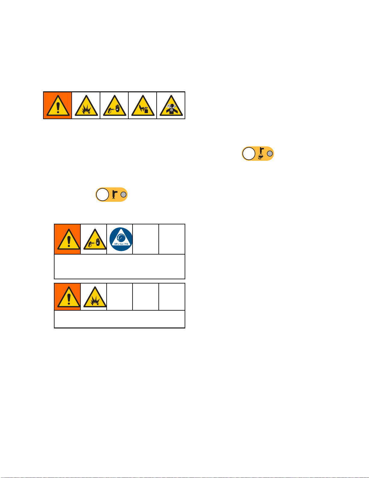
Pressure Reli
Follow the Pressure Relief Procedure
whenever you see this symbol.
This equipment stays pressurized until pressure
is manually relieved. To help prevent serious
injury from pressurized fluid, such as skin injection,
splashing fluid and moving parts, follow the
Pressure Relief Procedure whenyoustopspraying
and before cleaning, checking, or servicing the
equipment.
ef Procedure
Without Color Change
NOTE: The following procedure relieves all fluid and
air pressure in the system.
1. Turn off the supply pumps. Open the drain valve
on the supply line fluid filter to relieve pressure
in the supply line.
NOTE: If your system does not include a drain
valve on the supply line, set the mix manifold
With Color Change
NOTE: The following procedure relieves all fluid and
air pressure in the system.
1. Turn off the su
on the supply l
the supply li
NOTE: If your
valveonthes
SPRAY and pr
B dosing pum
pumps. Repe
If you are using a high pressure gun, engage
the trigger lock. Remove the spray tip and
clean it separately.
If using
statics before flushing the gun.
electro
pply pumps. Open the drain valve
ine fluid filter to relieve pressure in
nes. Do this for each color.
system does not include a drain
upply line, set the mix manifold to
ess
ps a couple of times to drain the
at for each color.
an electrostatic gun, shut off the
.CycletheAand
to SPRAY and press
and B dosing pumps a couple of times to drain
the pumps.
2. Press Standby
relieve pressure.
3. Set the mix manifold to FLUSH.
Flush the mix manifold and gun. See
Flush Mixed Material, page 27.
4. Shut off the solvent supply pump. To relieve
pressure, press Purge
the gun. Press Standby
pressure is relieved, to avoid getting a Purge
Incomplete alarm.
NOTE: If pressure remains in the solvent line
between the solvent supply pump and the solvent
valve,VERYSLOWLYloosenafittingtorelieve
pressure gradually.
.CycletheA
. Trigger the gun to
and trigger
when
2. Set the mix manifold to SPRAY. Trigger the gun
to relieve pressure. Repeat for each color.
3. Press Purge
Hold the gun trigger open after the solvent valve
shuts off to relieve all pressure.
4. Set the system to Recipe 0 to flush the system
from the pumps to the gun. When flushing is
complete the system will go to Standby.
5. Shut off the solvent supply pump. To relieve
pressure, press Purge
the gun. Press Standby
pressure is relieved, to avoid getting a Purge
Incomplete alarm.
NOTE: If pressure remains in the solvent line
between the solvent supply pump and the solvent
valve, VERY SLOWLY loosen a fitting to relieve
pressure gradually.
. Repeat for each color.
and trigger
when
332562B 29
Page 30

Operation
Valve Setting
Dose valves and purge valves are factory set with the
hex nut (E) 1-1/4 turns out from fully closed.
Figure 14 Valve Adjustment
s
Shutdown
1. Flush out the mixed material to avoid potlife errors
and fluid setup in the lines. See Purging, page 27.
2. Follow the Pressure Relief Procedure, page 29.
3. Close the main air shutoff valve on the air supply
line and on the control box.
4. Press
power to the pumps.
5. Shut off system power (0 position).
on the Display Module to turn off
30 332562B
Page 31

Run Mode Screens
Run Mode Scree
NOTE: Selection fields and buttons that are
grayed-out on the screens are not currently active.
ns
Splash Screen
At power up,
approximat
screen.
the Graco logo will display for
ely 5 seconds, followed by the Home
Home Screen
The Home screen displays the current status of the
system. The following table details the information
shown.
Figure 15 Splash Screen
To view pump flow rates and pressures
(as shown), select “Diagnostic Mode” on
System Screen 1, page 39.
Figure 16 Home Screen, in Mix Mode with
Diagnostics On
332562B 31
Page 32
Run Mode Screens
Home Screen Key
Key Description Details
ADateandTime
BMenuBar
C Status B
ar
See Advanced Screen 1, page 55,toset.
Run Screens. U
different Ru
• Home (shown in Diagnostic Mode)
• Spray (see Spray Screen, page 34)
• Fill (see Fill Screen, page 35)
• Potlife (present only when “Multiple Guns is selected on System Screen 3, page 42.Seealso
Information for Systems with Multiple Guns, page 43.
• Usage (see Usage Screen, page 36)
•Jobs(seeJobs Screen, page 37)
•Errors(seeErrors Screen, page 37)
•Events(seeEvents Screen, page 37)
System S
•PumpOff
• Standby
•Startup
•Mix
se left and right arrow keys to scroll through the
n screens:
tatus: Displays the current mode of operation:
• Change Recipe
•Idle
•PrimePump
• Calibrate
• Fill
•Purge
• Shutdown
D
Error Status
ays any active error code.
Displ
•StallTest
• Maintenance Test
32 332562B
Page 33

Key Description Details
E Pump Animation and
Diagnostic Information
Run Mode Screens
F
G Material (A or B)
H
J
K Pump Inlet Pressure
L Pump Flow Rate
M
N
P Pump Indicator Light
S Solvent Flow Rate Shows solvent flow rate, if a solvent meter is attached.
T
Pump Number (1
Available Colors
Pump Inlet C
Pump Outlet Color
Pump Outl
• Clear = power off
• Yellow = standby
• Green = active
Gun An
imation
–4)
olor
et Pressure
Shows
Gun an
•
mixed material in gun and displays active recipe at gun.
imation changes to show:
(Mix
Fill)
•
PurgeinGFB)
(Gun
U
V
W
X
Y
Z
Active Recipe (
Current Ratio (
Potlife Time Remaining (
Total Volume for the Current
Job (
Current Flow Rate (
Current Pressure (
)
)
)
)
)
•
•
•
)
(Mix With Air Flow)
(Recipe Standby)
urge)
(P
•
Standby, in GFB)
•
•
(Purged Gun in
(Solvent Standby)
MixWithNoAirFlow)
(
332562B 33
Page 34

Run Mode Screens
Spray Screen
The Spray screen displays the following information:
• Active Recipe
• Target Ratio
• Actual Ratio
• Target Press
• Actual Pres
• Actual Flow
• Potlife Re
•GunAnimat
sure
maining
(can be changed on this screen)
ure (can be changed on this screen)
ion
Figure 18 Spray Screen, in Mix Mode
Figure 17 Spray Screen, in Standby Mode
e 19 Spray Screen, in Idle Mode
Figur
34 332562B
Page 35

Fill Screen
The Fill screen displays the following information for
the pump assigned to the current color:
Run Mode Screens
• Material. Se
The pump anim
show the sele
enter the pum
• Flush Line (
Select this
material li
sequence 1.
To prime the pumps and fill the lines,firstread
Prime and Fill the System, page 25.
1. Press the Edit softkey
for editing.
2. Select Color (A).
3. Enter the color number in the box to the right.
4. If the selected material is not already loaded,
press the Prime softkey
prime Color (A) into the selected pump through
the selected color valve and out the outlet dump
valve.
lect Color (A), Catalyst (B), or Solvent.
ation at the top of the screen will
cted material. If solvent is selected,
pnumberintheboxtotheright.
only for systems with color change).
box if you want to flush the specified
ne with solvent. The system uses flush
to open the screen
. The system will
Figure 20 Fill Screen, Color (A) Selected
5. Press the Fill softkey
attempt to fill the Color (A) lines until the user
presses Stop
container.
6. Repeat for Catalyst (B).
ush the system (pump and fluid lines), see
To fl
sh the System, page 28.
Flu
To flush only the pump:
1. Press the Edit softkey
for editing.
2. Select Solvent.
3. Enter the pump number in the box to the right.
4. Press the Prime softkey
flush solvent through the selected pump and out
thedumpvalve.
. Trigger the gun into a waste
. The system will
to open the screen
. The system will
e 21 Fill Screen, Solvent Selected
Figur
332562B 35
Page 36

Run Mode Screens
Usage Screen
The first Usage screen displays the current job usage
and grand total usage of component A, B, A+B, and
solvent (S). The second Usage screen displays the
total volume pumped for all available materials.
1. Press the Edit softkey
for editing.
2. To enter or change the User ID (
field to open the User ID Keyboard screen,
and enter the desired name (10 characters
maximum).
3. To log the current job, press the Job Complete
softkey
fields and increment to the next job number.
The Grand Totals cannot be cleared. See the
Jobs Screen, page 37, to review past jobs.
4. Press the Edit softkey
. This will clear the current usage
to open the screen
), select the
to close the screen.
Figure 23 User ID Keyboard Screen
e 24 Usage Log
Figur
Figure 22 Usage Screen
36 332562B
Page 37

Run Mode Screens
Jobs Screen
The Jobs screen displays the 200 most recent job
numbers, recipes, and A+B volumes in a log, with
date, time, and User ID.
Figure 25 Jobs Screen
Errors Screen
The Errors screen displays the 200 most recent Error
Codes in a log, with date, time, and description.
Figure 26 Errors Screen
Events Screen
The Events screen displays the 200 most recent
Event Codes in a log, with date, time, and description.
Figure 27 Events Screen
332562B 37
Page 38

Setup Mode Scree
ns
SetupModeScr
Press on any Run screen to enter the Setup
screens.
NOTE: Selection fields and buttons that are
grayed-out on the screens are not currently active.
If the system
screen disp
has a password lock, the Password
lays. See Password Screen, page 38.
eens
Password Screen
Figure 28 Password Screen
Enter the 4 digit password, then press
screen 1 will open, allowing access to the other
Setup screens.
.System
Entering an incorrect password clears the field.
Reenter the correct password.
To assign a password, see
Advanced Screen 1, page 55.
38 332562B
Page 39

Setup Mode Scree
ns
System Screen
System screen 1 includes the following fields which
define your system.
Figure 29 System Screen 1, During Standby
1
Diagnostic Mode
Select this box to display flow rate and pressure for
eachpumpontheHome Screen, page 31.
Color Pumps
Enter the number of color pumps in your system.
Catalyst Pumps
Enter the number of catalyst pumps in your system.
Non-Mix Pressure
Enter a lower pressure for use when not mixing and
spraying (for example during fill or flushing).
NOTE: Low
(0.7 MPa,
pressur
bar) low
Solvent
pressure systems may be set 100 psi
7 bar) lower than target pressure; high
e systems may be set 300 psi (2.1 MPa, 21
er than target pressure.
Meter
Figure 30 System Screen 1, During Idle
Select t
The Sol
Solven
Enter
Selec
Selec
The A
Auto
Sele
his box if your system uses a solvent meter.
vent K-Factor field will then become active.
tK-Factor
the solvent meter K-Factor.
t Gun Flush Box
t this box if your system uses a gun flush box.
utodump function will then become selectable.
dump
ct this box to activate the Autodump function.
332562B 39
Page 40

Setup Mode Scree
ns
System Screen
System screen 2 sets the following system operating
parameters.
Figure 31 System Screen 2, in Standby Mode
2
Mix Pressure Tolerance
The pressure of one component must be within
a percentage (±) of the pressure of the other
component during spray or mix. Set the desired Mix
Pressure Tolerance in this field. The default is 75%.
Mix Idle Timeout
The air flow switch (AFS) detects air flow to the gun
and signals that the gun is triggered. If you are not
using an air flow switch, the system does not know if
the gun is spraying. If a pump failed you could spray
pure resin or catalyst without knowing. This should
be caught by the Mix No Flow Timeout; the default
is 5 seconds. The Mix Idle Timeout will trigger Idle
mode, which will run a pump stall test to check for
leaks, then put the pumps in Standby (holding their
current position) after the designated period of time.
Enter the desired Mix Idle Timeout in this field.
See Air F
Mix No Fl
low Switch (AFS) Function, page 61.
ow Timeout
re 32 System Screen 2, in Mix Mode
Figu
The air
and sig
switch
no fluid
resin o
Timeou
desig
Enter
See Air Flow Switch (AFS) Function, page 61.
flow switch (AFS) detects air flow to the gun
nals that the gun is triggered. If the air flow
indicates that the gun is triggered, but there is
flow through a pump, you could spray pure
r catalyst without knowing. The Mix No Flow
t will cause the system to shutdown after the
nated period of time. The default is 5 seconds.
the desired shutdown time in this field.
40 332562B
Page 41

Setup Mode Scree
ns
Stall Test Pressure
Set the minimum stall test pressure. The setting
should be approximately 50 psi (0.35 MPa, 3.5 bar)
higher than the highest inlet pressure.
Pump Stall Test
Set the duration for the pump stall test. See
Calibrate Screen 1, page 51.
Maximum Leak Rate
Enter the maximum allowable leak rate for a pump
stall test.
Mix Fill Set Point
Set a higher pressure for use while mix filling.
This higher pressure decreases the time needed
to fill the gun. Once the gun is filled, the system
uses the recipe’s target pressure setpoint (set on
Recipe Screen, page 45)formixing.
The default v
ignores the M
Non-Mix Pres
while mix fil
alue is 0. When set to 0, the system
ix Fill Set Point and instead uses the
sure (set on System Screen 1, page 39)
ling.
332562B
41
Page 42

Setup Mode Scree
ns
System Screen
System screen 3 sets the following system operating
parameters.
Figure 33 System Screen 3
3
Multiple Guns
Enable this option if multiple guns will be loaded
with mixed material at the same time. This feature
will track the pot life of up to 60 different guns. See
Information for Systems with Multiple Guns, page 43.
Gun Hose Length
Enter the length of the hose from the mix manifold
to the gun.
Gun Hose Diameter
Enter the diameter of the hose from the mix manifold
to the gun. The minimum diameter is 1/8 in. (3 mm).
Mix At Wall
Select this box if a remote mix manifold is used in
your system.
NOTE: If Multiple Guns is enabled, the Gun Hose
Length, Gun Hose Diameter, and Mix at Wall fields
are disabled.
gure 34
Fi
Figure 35
Hose Length and Diameter
Enter the length and diameter of the hose from the
remote color stack to the remote mix manifold, for
both A and B hoses.
NOTE: These fields are enabled only if Mix at Wall
is enabled.
2
4
332562B
Page 43

Setup Mode Scree
ns
Information f
The Multiple guns feature enables the ability to
simultaneously track up to 60 different mixed material
recipes, each loaded into a dedicated gun. This
feature is enabled on System Screen 3, page 42.
Recipe Scree
Because the s
recipe, the
could be uni
disabled on
appear on th
hose lengt
aparticul
h and diameter for a gun that will spray
ar recipe.
or Systems with Multiple Guns
n
ystem has a dedicated gun for each
associated hose length and diameters
que. Therefore, these parameters are
System Screen 3, page 42, and now
e Recipe Screen, page 45. Enter the
Changing Recipes or Purging
When Multiple Guns is enabled, the Spray Screen
allows the user either to change the active recipe
(the recipe that is loaded in the pumps) or to purge
a particular gun (recipe). Select either Recipe or
Purge from the dropdown menu and enter the recipe
number. Use the Purge soft key to purge the active
recipe.
These actio
Control. Us
the active
Booth Cont
active cur
the desir
Purge is n
will reve
nsalsocanbedoneusingtheBooth
e the normal procedure to change
recipe or to purge the active gun. See
rol, page 22. To purge a gun that is not
rently, scroll Up
ed recipe. Then press Purge
ot pressed within 5 seconds, the system
rt to the active recipe number.
or Down to
.If
Figure 36
Potlife Screen
In Run mode, the Potlife Screen appears in the menu
bar between Fill and Usage. This screen displays
how much time remains in the potlife of any given
recipe (gun). Recipes are highlighted and show
remaining potlife time only if that gun is filled with
mixed material and has a non-zero potlife.
igure 37
F
Figure 38
332562B 43
Page 44
Setup Mode Scree
ns
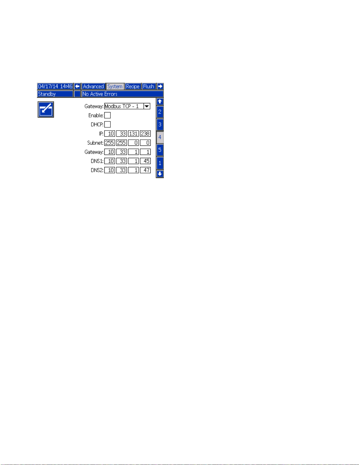
System Screen
System screen 4 sets the following system operating
parameters. This screen is needed only for systems
that use AWI.
Figure 39 System Screen 4
4
Gateway ID
Select the desired Gateway ID from the dropdown
menu.
Enable
Uncheck Enable while setting the IP Address, Subnet
mask, Gateway, DNS1 or DNS2. When the settings
are loaded, check the Enable box to write the new
settings to the selected Gateway.
Checkthisb
that the PLC
ox to enable the selected Gateway so
can communicate with it.
DHCP
Select thi
Configurat
unique IP a
renews the
the netwo
Gateway fi
the addre
s box if your system has a Dynamic Host
ionProtocol(DHCP).Thisprotocolassigns
ddresses to devices, then releases and
se addresses as devices leave and rejoin
rk. If selected, the IP Address, Subnet, and
elds will not be editable and will display
sses supplied by the DHCP.
TCP/IP
Use the r
mask, Ga
emaining fields to set the IP address, subnet
teway, DNS1, and DNS2.
4
4
332562B
Page 45

Recipe Screen
Setup Mode Scree
ns
Figure 40 Valid Recipe Screen
Recipe
Enter the desired recipe number (1-60).
Recipe 0
UseRecipe0toflushthesystem.
• If a recipe (1–60) is loaded: Select Recipe 0 to flush
the previously active pumps and purge the gun.
• If Recipe 0 or 61 is loaded: SelectRecipe0to
flush all pumps and purge the gun.
Enabled
Selecting “Enabled” makes the selected recipe
accessible from the booth control, in addition to the
ADM. The booth operator can then quickly select a
desired recipe, without scrolling through all 60.
Color (A) Valve
Enter the desired color valve number (1-30).
NOTE: If you enter a number which is not valid in
your system configuration, the field will be highlighted
and the recipe becomes invalid. For example, if your
configuration has 8 color valves and you enter 30,
the field will appear as shown below.
Figure 41 Invalid Recipe Screen
Catalyst (B) Valve
Enter the desired catalyst valve number (1-4).
NOTE: If you enter a number which is not valid in
your system configuration, the field will be highlighted
and the recipe is invalid. For example, if your
configuration has 1 catalyst valve and you enter 4,
the field will be highlighted and the recipe is invalid.
Flush Sequence
Enter the desired flush sequence (1-5). For hard
to flush colors, select a longer sequence. 1 is the
default, and should be designated for the longest,
most thorough flush duration.
If Mix at Wall is enabled on System Screen 3, enter
the desired flush sequence (105) for the color (A)
valve and the catalyst (B) valve. The gun purge time
for each material depends on the flush sequence
assigned to each. See Flush Screen, page 47.If
materials A and B require different purge times,
assign separate flush sequences. Set the necessary
gun purge time for each. For hard to flush colors,
select a longer sequence. Flush sequence 1 is the
default, and should be designated for the longest,
most thorough flush duration.
Mix Ratio
Enterthedesiredmixratio(0to50.0):1.
Potlife Time
Enter the potlife time (0 to 999 minutes). Entering
0 disables this function.
332562B 45
Page 46

Setup Mode Scree
ns
Pressure Low Limit
Enter the lowest target pressure which the operator
is allowed to enter from the Spray screen or booth
control. The default is 5 psi (.035 MPa, 0.35 bar).
Target Pressure
Enter the desired target spray pressure. This is the
pressure the pumps will maintain at the outlet. The
default is 20 psi (0.14 MPa, 1.4 bar).
Pressure High Limit
Enter the highest target pressure which the operator
is allowed to enter from the Spray screen or booth
control. The default is 300 psi (2.1 MPa, 21.0 bar).
NOTE: If you en
system’s par
the recipe is
psi (10.5 MPa
the field will
invalid.
ter an invalid pressure for your
ameters, the field will be highlighted and
invalid. For example, if you enter 1500
, 105 bar) in a low pressure system,
be highlighted and the recipe becomes
46 332562B
Page 47

Flush Screen
Figure 42 Flush Screen
Flush Number
Setup Mode Scree
ns
Gun Purge Time
Enter the gun purge time (0 to 999 seconds).
Initial Flush
Entertheinitialflushvolume(0to9999cc).
Final Flush
Enter the final flush volume (0 to 9999 cc).
Wash Cycles
A Wash Cycle activates the pump with the valves
closed, to use pumping motion to thoroughly clean
the pump. Enter the desired number of wash cycles
(0 to 99). Entering a number will make the Strokes
per Cycle field active.
Enter the desired flush sequence (1-5). For hard
to flush colors, select a longer sequence. 1 is the
default, and should be designated for the longest,
most thorough flush duration.
Strokes per Wash Cycle
Enter the desired pump strokes per wash cycle (0
to 99). Default is 1.
332562B
47
Page 48

Setup Mode Scree
Pump Screen 1
ns
NOTE: Your system may include 2, 3, or 4 pumps.
Information for each pump is accessible under a
separate tab in the menu bar at the top of the screen.
Select the tab for the desired pump. Each pump has
three screens. Only the screens for Pump 1 are
shown here, but the same fields appear on all.
Pump screen
define the pu
Figure 43 Pump Screen 1 — Resin Pump
1 includes the following fields which
mp.
Select Color Change
Select this box if your system uses color change.
Materials
Enter the number of materials used in your system.
Each color change module controls 8 colors.
Total Hose Length
Compute the length of the hoses from the supply
stack to the pump and from the pump to the outlet
stack. Enter the total length.
Pump Hose Diameter
Enter the diameter of the supply and output hoses.
Valve Mapping
Remote Valve Map
NOTE: Th
if the pu
selecte
System
is valve mapping dropdown menu displays
mp is a resin pump with Color Change
d on this screen and Mix at Wall enabled on
Screen 3, page 42.
Figure 44 Pump Screen 1 — Catalyst Pump
Pump Size
Select 35cc or 70cc, as appropriate.
Inlet Pressure
Select one of the following:
• Disabled
Select whether to use the standard color change
valve mapping or one of two alternate color change
valve mappings for the remote valve stack. See the
Color Change and Remote Mix Manifold manual
333282 for more information.
Valve Map
NOTE:
if th
sele
Select whether to use the standard color change
valve mapping or the alternate color change valve
mapping for the catalyst pump(s). See the Color
Change and Remote Mix Manifold manual 333282
for more information.
This valve mapping dropdown menu displays
e pump is a catalyst pump with Color Change
cted on this screen.
Available Colors
The module displays the number of colors available
in your system. This field is not editable.
• Monitor, to track inlet pressure
48 332562B
Page 49

Pump Screen 2
Setup Mode Scree
ns
Pump screen 2 sets the pressure transducer settings
for the pump.
Figure 45 Pump Screen 2, Default Settings Enabled
Default Settings Selected
When the “Use Default Settings” box is selected,
default settings are used for the calibration values,
and the fields are grayed out.
Default Settings Not Selected
When the “Use Default Settings” box is not selected,
the following calibration values must be entered.
Invalid values will be over-ridden and the system will
automatically select the default settings.
•InletOffs
Pressure i
Monitor; i
valid ran
•InletSen
Inlet Pre
to Monito
valid ra
•OutletO
+01.20 m
•OutletS
to 21.2
et Factor: This field is only used if Inlet
n Pump Screen 1, page 48 is set to
t is grayed out if set to Disabled. The
ge is -01.20 to +01.20 mV/V.
sitivity Factor: This field is only used if
ssure in Pump Screen 1, page 48 is set
r; it is grayed out if set to Disabled. The
nge is 18.80 to 21.20 mV/V.
ffset Factor: The valid range is -01.20 to
V/V.
ensitivity Factor: The valid range is 18.80
0mV/V.
re 46 Pump Screen 2, Default Settings Disabled
Figu
332562B 49
Page 50

Setup Mode Scree
ns
Pump Screen 3
Pump screen 3 sets the pressure alarm limits for the
pump.
When Inlet Pr
set to Disabl
out and only t
Pressure Ala
Figure 47 Pump Screen 3, Pressure Monitoring
Disabled
When Inlet Pressure in Pump Screen 1, page 48 is
set to Monitor, all fields are active. See
Pressure Alarm and Deviation Limits, page 50.
essure in Pump Screen 1, page 48 is
ed, the inlet limit fields are grayed
he outlet limit fields are active. See
rm and Deviation Limits, page 50.
Figure 48 Pump Screen 3, Pressure Monitoring
Enabled
Pressure Alarm and Deviation Limits
Inlet fields are only active if Inlet Pressure
in Pump Screen 1, page 48 is set to Monitor; they
are grayed out if set to Disabled. Outlet fields are
active at all times.
• Alarm and Deviation ranges are 0-300 psi for
low pressure systems, and 0-1500 psi for high
pressure systems.
• Setting to 0 will disable the alarm. The Inlet Alarm
High and Outlet Alarm High cannot be disabled.
• Alarms and Deviations will display when the inlet
or outlet pressure drops below the low limit or
exceeds the high limit.
50 332562B
Page 51

Setup Mode Scree
ns
Calibrate Scr
Calibrate Screen 1 initiates a pump pressure check
(stall test) for the selected pump. During the test, the
Stall Test screen will appear.
The pump and lines must be primed with color
or catalyst before doing the stall test. See
System Screen 2, page 40 to set test parameters.
See Pump Pressure Check, page 57 for complete
test instructions.
To initiate the test, press the Pressure Check
button for the desired pump. The pump will build
pressure in the line to a minimum of the Stall Test
Pressure. The pump will then move to the center
stroke position and stall test the upstroke, followed
by the downstroke.
NOTE: TheLastPassedlogcanonlyberesetby
successfully completing the test.
The screen displays the number of days since the
last stall test was passed for each pump.
een 1
Calibrate Scr
Calibrate Screen 2 initiates a volume test for the
selected pump. During the test, the Volume Check
screen will appear.
The pump and l
or catalyst b
Pump Volume C
instructio
To initiate
button for
The screen displays the volume dispensed. Press
Press an
seconds
ns.
the test, press the Volume Check
the desired pump.
to end the test.
d hold the Reset button
to reset the volume counter.
een 2
ines must be primed with color
efore doing the Volume Check. See
heck, page 58 for complete test
for 1-2
Figure 51 Calibrate Screen 2
Figure 49 Calibrate Screen 1
igure 52 Volume Check Screen
F
Figure 50 Stall Test Screen
332562B 51
Page 52

Setup Mode Scree
ns
Calibrate Scr
Calibrate Screen 3 initiates a calibration of an
accessory solvent meter. During the test, the Volume
Verification screen will appear.
The meter and
solvent befo
Solvent Mete
instructio
To initiate the calibration, press the Volume Check
The screen displays the volume dispensed. Enter
the amount of solvent dispensed in the Measured
Volume field, or press
After the
Calibra
the cal
and ret
ns.
button.
Measured Volume is entered, the Accept
tion window will appear. Press
ibration. Press
ain the previous K-factor.
een 3
lines must be primed with
re doing the calibration. See
r Calibration, page 59 for complete
to end the test.
to accept
to cancel the calibration
Figure 54 Enter Measured Volume of Solvent
Press and hold the Reset button
seconds to reset the volume counter.
Figure 53 Calibrate Screen 3
for 1-2
e 55 Accept Calibration
Figur
52 332562B
Page 53

Setup Mode Scree
ns
Maintenance S
Use this screen to set maintenance intervals. Set
to0todisablethealarm.
NOTE: The Pum
must enter a v
Figure 56 Maintenance Screen 1, Interval Settings
creen 1
p Stall Test cannot be disabled. You
alue other than 0.
Maintenance Screen 2
Maintenance S
Maintenance screen 3 shows the current interval
status of the pump maintenance tests.
Press and hold the Reset button
seconds to clear the alarm and reset the counter.
NOTE: ThePumpStallTestcanonlyberesetby
successfully completing the test.
creen 3
for 1-2
Maintenance screen 2 shows the current interval
status of the solvent meter, fluid filter, and air filter.
Press and hold the Reset button
seconds to clear the alarm and reset the counter.
Figure 57 Maintenance Screen 2, Current Status
for 1-2
Figure 58 Maintenance Screen 3, Current Pump
Status
332562B 53
Page 54

Setup Mode Scree
ns
Maintenance S
Maintenance screen 4 displays cycle counts for a
selected color, catalyst, or solvent valve.
Press and hold the Reset button
seconds to reset the counter.
If the syste
or closed by
correspond
NOTE: Gun valves are available only if Mix at Wall is
enabled on System Screen 3, page 42.
m is in Standby, valves can be opened
selecting or deselecting the box for the
ing valve.
creen 4
for 1-2
Figure 60 Maintenance Screen 4, Solvent Valve
Resets
NOTE: When Solvent is selected in the Material
field, the number to the right of “Solvent” is the pump
number, not the material number.
Figure 59 Maintenance Screen 4, Color Valve Resets
54 332562B
Page 55

Setup Mode Scree
ns
Advanced Scre
Advanced screen 1 sets the following display
parameters.
Figure 61 Advanced Screen 1
en 1
Language
Defines the language of the screen text. Select:
• English (default)
• Spanish
•French
•German
• Japanese
•Chinese
•Korean
•Dutch
• Italian
uguese
•Port
•Swedish
•Russian
Date Format
Select mm/dd/yy, dd/mm/yy, or yy/mm/dd.
Date
Enter the date, using the format selected. Use two
digits for the month, day, and year.
Time
Enter current time in hours (24 hour clock) and
minutes. Seconds are not adjustable.
Password
The password is only used to enter Setup mode.
The default is 0000, which means no password is
required to enter Setup. If a password is desired,
enter a number from 0001 to 9999.
NOTE: Be
it in a s
Screen
Select
5isth
saver
Silen
Sele
audi
sure to write down the password and keep
ecure location.
Saver
the desired screen timeout in minutes (00-99).
e default. Select zero (0) to disable the screen
.
tMode
ct Silent Mode to disable the alarm buzzer and
ble feedback.
332562B 55
Page 56

Setup Mode Scree
ns
Advanced Scre
Advanced screen 2 sets display units (US or metric).
Figure 62 Advanced Screen 2
en 2
Display Units
Select the desired display units:
• Grand Total Volume (US gallon or liter)
• Pressure (psi, bar, or MPa)
Enable USB Downloads/Uploads
Select this box to enable USB downloads and
uploads. Enabling USB activates the Download
Depth field.
Download Depth
Enter the number of days for which you want to
retrieve data. For example, to retrieve data for the
previous week, enter 7.
Log 90% Full Advisory Enabled
This selection is enabled by default. When enabled,
the system will issue an advisory if the memory log
has reached 90% of capacity. Perform a download to
avoid loss of data.
Advanced Screen 4
Advanced
numbers
This is n
screen 4 displays the software part
and versions for the system components.
ot an editable screen.
• Length (ft or m)
Advanced Screen 3
Advanced screen 3 enables USB downloads and
uploads.
Figure 63 Advanced Screen 3
Figure 64 Advanced Screen 4
56 332562B
Page 57

Calibration Che
cks
Calibration C
Pump Pressure
NOTE: Enter the transducer calibration data before
doing the pressure check.
Perform the pressure check:
• The first time the system is operated.
• Whenever new materials are used in the system,
especially if the materials have viscosities that
differ significantly.
• At least once per month as part of regular
maintenance.
• Whenever a pump is serviced or replaced.
During each pressure test, the dose valve will close
during an up stroke and a down stroke (in either
order). This test is to verify that the valves are
seating properly and not leaking. If leaking occurs,
the system will alarm after the test for that particular
pump direction.
NOTE: Do not trigger the gun during the pressure
check.
1. Set the mix manifold to the SPRAY position.
hecks
Check
2. The pump and lines must be primed with color or
catalyst before doing the Pressure Check. See
PrimeandFilltheSystem,page25.
3. If the display is on a Run Mode screen, press
to access setup screens.
4. Scroll to Calibrate to display
Calibrate Screen 1, page 51.
5. Press the Pressure Check
desired pump. The pump will build pressure in
the line to a minimum of the Stall Test Pressure.
The pump will then move to the center stroke
position and stall test the upstroke, followed by
the downstroke.
6. The pressure and flow that the unit measured
are displayed on the screen. Compare
with the maximum leak rate entered on
System Screen 2, page 40. If the values are
substantially different, repeat the test.
NOTE: The stall test pressure set point is a
minimum. The system may stall at a higher
pressure depending on hose lengths and fluid
composition.
button for the
332562B 57
Page 58

Calibration Che
cks
Pump Volume Ch
1. Set the mix manifold to the SPRAY position.
2. The pump and lines must be primed with color or
catalyst before doing the Volume Check. See
PrimeandFilltheSystem,page25.
3. If the display is on a Run Mode screen, press
to access setup screens.
4. Scroll to Calibrate in the menu bar.
5. Scroll to Calibrate Screen 2, page 51.
6. Press the soft key
to check.
NOTE: For maximum accuracy, use a gravimetric
(mass) method to determine the actual volumes
dispensed. Verify that the fluid line is filled and
at the proper pressure before checking. Air in
the line or pressure that is too high may cause
incorrect values.
eck
for the pump you want
7. Press the Reset key
will reset to 0.
8. Trigger the gun into a graduated cylinder.
Dispense a minimum of 500cc of material.
9. The volume that the unit measured displays on
the screen.
10. Compare the amount on the screen to the
amount in the graduated cylinder.
NOTE: If the value is substantially different,
repeat the test. If the dispensed volume and
measured volume still do not match, check that
the A and B pump positions are not reversed.
NOTE: Stop triggering the gun and press
to cancel the test.
. The volume counter
58 332562B
Page 59

Calibration Che
cks
Solvent Meter
1. Set the mix manifold to the FLUSH position.
2. The meter and lines must be primed with
solvent before doing the calibration. See
Prime and Fill the System, page 25.
3. If the display is on a Run Mode screen, press
to access setup screens.
4. Scroll to Calibrate in the menu bar.
5. Scroll to Calibrate Screen 3, page 52.
6. Press the soft key
NOTE: For maximum accuracy, use a gravimetric
(mass) method to determine the actual volumes
dispensed.
NOTE: Verifythatthefluidlineisfilledandatthe
proper pressure before calibrating. Air in the line
or pressure that is too high may cause incorrect
calibration values.
Calibration
to initiate the calibration.
7. Trigger the gu
Dispense a min
8. The volume tha
the screen.
9. Compare the a
amount in the
NOTE: If the
repeat the c
10. Enter the am
Measured V
11. After the m
controlle
K-factor a
standard m
12. Press
to cance
K-facto
value is substantially different,
alibration process.
ount of solvent dispensed in the
olume field on the screen.
easured volume is entered, the
r calculates the new solvent meter
nd displays it on the screen. The
eter K-factor is 0.021 cc/pulse.
to
l the calibration and retain the previous
r.
n into a graduated cylinder.
imum of 500cc of material.
t the unit measured displays on
mount on the screen to the
graduated cylinder.
accept the calibration. Press
332562B 59
Page 60

Color Change
Color Change
Color Change Module Kits are available as an
accessory. See manual 332455 for complete
information.
Single Color Systems
1. Follow the p
Flush the Sy
2. Load the new
Prime and F
3. Press the M
rocedure under
stem, page 28.
color. See
ill the System, page 25.
ix key
to start spraying.
Multiple Color Systems
1. Press Standby .
2. Set the current mix manifold to FLUSH.
3. Select the new recipe at the Booth Control or
on the Spray Screen, page 34. This will change
colors in the pump and initiate a gun purge. The
Standby and Purge indicators should be blinking.
NOTE: The booth control only displays enabled
recipes. If an invalid recipe is entered, the
display will show 4 dashes (— — — — ). See
Recipe Screen, page 45 to enable a recipe.
NOTE: If Mix at Wall is enabled on
System Screen 3, page 42, the system
will purge Material B first, then Material A
out of the gun. Each material will purge for
the amount of time designated by the Flush
Sequence selected for that material on the
Recipe Screen, page 45.
4. Hold a metal part of the gun firmly to a grounded
metal pail. Trigger the gun. Make sure there is
enough flow to open the solvent flow switch.
5. Release the trigger when the solvent flow stops
and the Purge indicator stops blinking.
NOTE: If you are using quick-disconnects at the
mix manifold, disconnect the gun from the purged
mix manifold and connect it to the new color line.
6. Wait for the color change to complete (the
Standby indicator is on solid).
7. Set the mix manifold to SPRAY.
8. Press the Mix key
control. The Mix indicator will be blinking.
9. Trigger the gun to complete the Mix Fill.
NOTE: There is a 30 second delay without flow
before the system will fault.
10. Wait for atomizing air and for the Mix indicator to
be on solid, then resume spraying.
on the booth
60 332562B
Page 61

System Errors
System Errors
System errors alert you of a problem and help
prevent off-ratio spraying. There are three types:
Advisory, Deviation, and Alarm.
An Advisory r
clear itself
A Deviation records an error in the system but does
not shut down the equipment. The deviation must be
acknowledged by the user.
If an Alarm occurs, operation stops.
If any of th
• Alarm buzzer sounds (unless in silent mode).
• Alarm popup screen shows the active alarm code
(see Error Codes, page 62).
• Status bar on the Advanced Display Module shows
the active alarm code.
• Alarm is saved in the date/time stamped log.
ecords an event in the system, and will
after 60 seconds.
e three types occur:
To Clear Error and Restart
NOTE: When a deviation or alarm occurs, be
sure to determine the error code before resetting
it. If you forget which code occurred, go to the
Errors Screen, page 37, to view the last 200 errors,
with date and time stamps.
If an alarm has occurred, correct the cause before
resuming operation.
To acknowl
on the Booth Control.
edge a deviation or clear an alarm, press
on the Advanced Display Module or
Air Flow Switch (AFS) Function
The air fl
and sign
The gun i
spray wh
If a pump fails, pure resin or catalyst could spray
indefinitely if the unit does not detect the condition
and intervene, which is why the AFS is so important.
ow switch (AFS) detects air flow to the gun
als the controller when the gun is triggered.
con on the Advanced Display Module shows
en the AFS is activated.
If the unit detects through the AFS signal that the gun
is triggered, yet one or both of the pumps are not
running, a Flow Not Detected Alarm (F8D1) occurs
after 10 seconds (default) and the system goes into
Standby.
332562B 61
Page 62

System Errors
Error Codes
NOTE: When an error occurs be sure to determine the code before resetting it. If you forget which code
occurred, use the Errors Screen, page 37 to view the last 200 errors, with date, time, and description.
Purge Errors
Code
F7P1 Alarm Air Flow
SPD1
Type Description Problem
Switch On
Alarm
Gun Purge
Incomplete
Theairflowswitchis
indicating unexpected
atomizing air flow.
The system timed out
without reaching the
user-specified volume
of solvent for a purge.
Cause Solution
Air flow switch is stuck
in flow position.
Leak downstream in air
line or fitting.
Air supply pressure
fluctuation.
Solvent flow switch not
working.
Solvent flow is too low
to actuate the solvent
switch.
Gun is not triggered. Operator must continue
Mix manifold was not
set to flush position,
blocking solvent flow to
the spray gun.
Clean or replace switch.
Check for leaks and
tighten fittings.
Eliminate pressure
fluctuations.
Replace switch.
Increase solvent
pressure to drive a
high purge flow rate
flushing for configured
time, until the booth
control indicates purge
is completed.
Set manifold to flush
position.
Mix Errors
Code
QPD1
SND1
Type Description Problem
Alarm Flow
Detected
Solvent
Gun
Alarm,
then
Deviation
Alarm Mix Fill
Potlife
Expired
Incomplete
The solvent flow
switch is indicating
unexpected solvent
flow.
Potlife time has expired
before the system has
moved the required
amount of material
(potlife volume) through
the mixed material line.
The system timed out
before the mix fill cycle
loaded the gun with
mixed material.
Cause Solution
Solvent flow switch is
stuck in flow position.
There is a leak through
the solvent cutoff valve.
Purge process was not
completed.
Solvent supply shut off
or empty.
Mix manifold not set to
spray position.
Spray gun was not
triggered.
Restrictions in mixer,
manifold, or spray gun.
Clean or replace switch.F7S1
Check for leaks and
repair valve.
Make sure purge
process is completed.
Verify solvent supply
is available and on,
supply valves are open.
Setmanifoldtospray.
Allow flow through gun
during fill process until
the fill complete LED
stops flashing.
Fix restrictions.
62 332562B
Page 63

Pumping Errors
System Errors
NOTE: In some e
applicable co
last digit in t
component is p
Code
DA0#
DE0#
mponent number, which can vary. The unit’s display will show the applicable number as the
he code. For example, the F1S# code listed in this table will be displayed as F1S1 if the affected
ump 1, F1S2 for pump 2, and so on.
Type Description Problem
Alarm Exceeded
Alarm Leak
rror codes listed below, a # symbol is shown as the last digit. This symbol represents the
Cause Solution
Maximum
Flow Pump
#
ed
Detect
Pump #
Pump was driven to
its maximum allowed
speed.
This is
test fa
pump ca
pressu
“Stal
Will f
secon
a manual stall
ilure when the
nnot build
re to the target
l Test Pressure.”
ault after 30
ds.
System has a l
or open valve
allowing un
flow.
Pump is cavitating,
cycling without
restriction.
Viscosity of material is
too thin for nozzle size.
System pressure or
Flow Setpoint is too
high (causing the pump
to work too hard).
No mate
or line
Leak in the system.
rial in the pump
.
eak
that is
restricted
Inspect syst
leaks.
Verify that the pump
is being supplied with
material.
Reduce noz
create mo
Reduce pa
to lower t
Reduce the pressure or
the Flow Setpoint.
Make su
and dow
line ar
materi
Determine if leak is
external or internal
by visually inspecting
the system for fluid
leakage. Fix all loose
or worn hoses, fittings,
and seals. Inspect
all valve seats and
needles for wear, and
replace worn piston or
throat seals.
em for
zle size to
re restriction.
int pressure
he flow rate.
re the pump
n stream color
e loaded with
al.
DF0#
DG0#
rm
Ala
Alarm
No Stall Up
Pump #
No Stall
Down Pump
#
Pump failed the stall
test; did not stall on the
upstroke.
Pump failed the stall
test; did not stall on the
downstroke.
Valve failure, seal
failure, worn rod or
cylinder.
Valve failure, seal
failure, worn rod or
cylinder.
lace inlet and outlet
Rep
ve and seal for
val
stroke. Replace
up
ston and throat
pi
als. Replace rod and
se
linder as necessary.
cy
Replace inlet and outlet
valve and seal for
down stroke. Replace
piston and throat
seals. Replace rod and
cylinder as necessary.
332562B 63
Page 64

System Errors
Code
DH0#
DK0#
EBH#
EF0#
Type Description Problem
Alarm
Alarm Position
Record
Alarm Timeout
No Stall
Pump #
Pump #
Home
Complete
Pump #
Startup
Pump #
Pump failed th
test; did not s
either the ups
the downstrok
Pump was dete
be out of pos
Record of pump homing
is complete.
Pump tried but was not
able to move to the
home position within
a specified amount of
time.
estall
tall on
troke or
e.
cted to
ition.
Cause Solution
Valve failure
failure, worn
cylinder.
An indication on the
display that the pump
completed the home
function
Pump dose valves did
not actuate.
Motor could not drive
pumps and linear
actuator.
, seal
rod or
Replace inlet and outlet
valve and seal for up
and down strokes.
Replace piston and
throat seals. Replace
rod and cylinder as
necessary.
Re-enable pu
to reset pum
sure inlet s
pressure is
high.
No action required.
Verify ai
to soleno
Verify t
actuati
Verify motor is driving
the pump.
mp power
p. Make
upply
not too
rpressure
id valves.
he valves are
ng.
EF1#
Alarm Timeout
Shutdown
Pump #
Pump tried but was not
able to move to the
park position within a
specified amount of
time.
Pump stroke length
is shortened by
mechanical system
tolerance.
Pump dose valves did
not actuate.
p is filled with thick
Pum
nt and could not
pai
ve piston to end of
dri
oke. Motor or drive
str
orn or damaged.
is w
correct assembly
Verify
ar actuator and
of line
pump p
pump m
Visually inspect valves
to ensure they are
operating properly;
verify they have air
pressure above 85 psi
(0.6 MPa, 6.0 bar).
Obs
dri
ver
gen
iston rods. See
anual.
erve motor and
ve assembly to
ify that the motor is
erating force.
64 332562B
Page 65

System Errors
Code
F1F#
F1S#
F7D#
Type Description Problem
Alarm Flow Low
Fill Pump #
Alarm Flow Low
Purge Pump
#
Alarm Flow
Detecte
Pump #
d
There has been
or low flow duri
pump fill opera
There has b
or low flow
pump purg
The pump flow
exceeded 20 cc/min
flow coming into Idle
mode.
no flow
ng a
tion.
een no flow
during a
e operation.
Cause Solution
There is a restriction on
the outlet side of the
pump or color stack.
Thick viscos
requires mor
to pump.
The pumps do not
have to move for the
system to build enough
pressure to meet the
setpoint.
Restriction in the outlet
side of the pump or
color stack resulting in
the solvent flow being
too low.
There is
system o
open whe
went in
ity paint
e pressure
aleakinthe
r the gun was
n the system
to Idle mode.
Make sure there are no
restrictions in the color
stack and that the dump
valve is actuating.
Increase non
pressure if n
to create flow
the fill funct
Increase non-mix
pressure if necessary
to create flow during
the fill function.
Make sure there are
no restrictions in the
system. Increase
non-mix pressure if
necessary to create
flow during the purge
function.
Verify there are no
leaks in the system.
Make sure the air flow
switch is actuating
properly. Do not
trigger the gun without
atomizing air.
-mix
ecessary
during
ion.
F8D1 Alarm Flow Not
Detected
F9D#
SAD
Alarm Flow
Alarm Atomizing
1
able
Unst
Pump
Solvent
#
No flow
Thepumpflowrate
did not stabilize while
entering Idle mode.
Air
act
dil
unk
the
while mixing.
flow switch is
ive while solvent,
uted material, or an
nown material is in
gun.
Restriction in the outlet
side of the pump or
color stack.
tial leak in the
Poten
em.
syst
Atomizing air supply
was not shut off before
purging or filling spray
gun.
Make sure there are
no restrictions in the
system.
Check the system for
leaks and run manual
stall test.
Make sure atomizing
air is shut off before
purging or filling the
spray gun. Use an
AA cutoff valve on the
atomizing air supply.
332562B 65
Page 66

System Errors
Pressure Errors
NOTE: In some e
applicable co
last digit in t
component is p
Code
F6F#
P1F#
P2F#
P3D#
mponent number, which can vary. The unit’s display will show the applicable number as the
he code. For example, the P6F# code listed in this table will be displayed as P6F1 if the affected
ump 1, P6F2 for pump 2, and so on.
Type Description Problem
Alarm Press.
Alarm Pressure
Deviation
Deviation
rror codes listed below, a # symbol is shown as the last digit. This symbol represents the
Cause Solution
Disconnected
transducer.
Verify trans
connected pr
Replace if r
does not eli
alarm.
Increase inlet pressure.
Increase inlet pressure.
Relieve
pressur
ducer is
operly.
econnecting
minate the
system
e.
Sens.
Removed
Inlet #
Low Inlet
Pump #
Pressure
Low Inlet
Pump #
Pressur
High Out
Pump #
No inlet pressure
transducer is detected
when the system is
expecting one.
The inlet pressure on
pump#islessthan
the user-entered alarm
limit.
The inlet pressure on
pump#islessthanthe
user-entered deviation
limit.
e
let
The outl
on pump #
than the
deviati
et pressure
user entered
on limit.
is greater
P3F#
P4D#
P4F#
P6D#
P9D#
Deviation
Alarm Pressure
Alar
Alarm Press.
Al
m
arm
Pressure
High Inlet
Pump #
High Outlet
Pump #
sure
Pres
Inlet
High
#
Pump
Sens.
Removed
Outlet #
ess.
Pr
ns.
Se
iled
Fa
tlet #
Ou
The inlet pressure
on pump # is greater
than the user-entered
deviation limit.
The outlet pressure on
pump # is greater than
the user entered alarm
limit.
nlet pressure on
The i
# is greater than
pump
ser-entered alarm
the u
t.
limi
No outlet pressure
transducer is detected
when the system is
expecting one.
Outlet pressure
transducer has failed.
Disconnected
transducer.
Outlet pressure
transducer has failed or
thepressureisabove
the readable range.
Decrease inlet
pressure.
Relieve system
pressure.
ease inlet
Decr
sure.
pres
Verify transducer is
connected properly.
Replace if reconnecting
does not eliminate the
alarm.
lieve system
Re
essure. Verify
pr
nnections, or replace
co
reconnecting does
if
ot eliminate the alarm.
n
66 332562B
Page 67

System Errors
Code
P9F#
QADX
QBDX
Type Description Problem
Alarm Press.
Sens.
Failed Inlet
#
Alarm
Alarm
Differential
Pressure A
Over B
Differential
Pressure B
Over A
Inlet pressure
transducer has failed.
Low differential
pressure. This alarm is
active only during Mix
mode.
High differential
pressure. This alarm is
active only during Mix
mode.
Cause Solution
Inlet pressure
transducer has failed or
the pressure is above
the readable range.
There is a lea
Bside.
The B side pump is
cavitating.
There is a leak on the
Aside.
The A sid
ing.
cavitat
konthe
epumpis
Relieve system
pressure. Verify
connections, or replace
if reconnecting does
not eliminate the alarm.
Check the system
for internal and
external leaks on all
catalyst manifolds and
plumbing.
Check pain
the B side,
paint supp
Check the system
for internal and
external leaks on all
color manifolds and
plumbing.
Check paint supply on
the A side, increase
paint supply pressure.
t supply on
increase
ly pressure.
332562B 67
Page 68
System Errors
System Errors
Code
EB00 Rec-
EC00
EL00 Rec-
EM00 Rec-
EMIX Advi-
ES00
Commun
Type Description Problem
ord
Record
ord
ord
sory
Advisory
ication Errors
Stop Button
Pressed
Setup
Value(s)
Changed
System
Power On
System
Power Off
Pump Off
Factory
Defaults
Recordofastopbutton
press.
Record of cha
setup variab
Record of power cycle
(ON).
Record of p
(OFF).
The pumps
powered a
unable to
Record o
being lo
nging
les.
ower cycle
are not
nd are
move.
f defaults
aded.
Cause Solution
Indicates system stop
key on ADM was
pressed.
Indicates date and time
when setup values
were changed.
Indicates date and
time when system was
started.
Indicates date and
time when system was
turned off.
Pump powe
turned of
occurred
rwas
foranerror
.
n/a
n/a
n/a
n/a
Start pumps by
pressing pump start
key on Advanced
Display module.
n/a
NOTE: In some error codes listed below, a # symbol is shown as the last digit. This symbol represents the
applicable component number, which can vary. The unit’s display will show the applicable number as the last
digit in the code. For example, the CAC# code listed in this table will be displayed as CAC1 if the affected
component is color change board 1, CAC2 for board 2, and so on.
Code
CA0X
CAC#
CADX
Type Description Problem
Alarm
Alarm
arm
Al
Comm. Error
ADM
Comm. Error
Color Change
#
Comm. Error
Fluid Module
System does not
detect the Advanced
Display Module
(ADM).
System does not
detect the Color
Change Module #.
System does not
see the Enhanced
Fluid Control Module
(EFCM).
Cause Solution
ommunication
This c
r indicates that
erro
etwork has lost
the N
unication with
comm
dvanced Display
the A
le.
Modu
This communication
error indicates that
the network has lost
communication with
the Color Change
Module #.
is communication
Th
ror indicates that
er
he Network has lost
t
ommunication with
c
he EFCM.
t
Check CAN cable
connecting ADM to
the EFCM.
Check CAN cable
connections to
the Color Change
Module # and any
interconnected
modules.
Check CAN cables
connecting ADM to
the EFCM. Replace
Cable or EFCM as
necessary.
68 332562B
Page 69

System Errors
Code
CAGX
CDC#
CDDX
Type Description Problem
Alarm
Alarm Duplicate
Alarm Duplicate
Comm. Error
Gateway
Color Change
#
Fluid Modu
le
System does no
detect a CGM th
was registere
being connect
power up.
System detects two or
more identical Color
Change Modules.
System sees two
or more identical
Enhanced Fluid
Control Modules
EFCM).
t
das
ed at
at
Cause Solution
More than one Color
Change Module with
thesameaddress
is connected in the
system .
More than one EFCM
is connected in the
system.
Check the system
and remove the extra
color change module.
Check the system
and remove the extra
EFCM.
332562B 69
Page 70

System Errors
USB Errors
Code
EAUX Advisory
EBUX Record
EQU0
EQU1
EQU2
EQU3
EQU4
EQU5
EVUX Advisory
MMUXAdv
WSUX
WXUD Advisory
WXUU Advisory
Type Description Problem
Advisory
Record
Record
Record
Record
Record
isory
Advisory
USB Busy USB drive is inserted,
download is in
progress.
USB Drive
Removed
USB Idle USB downloa
USB Sys.
Settings
Downloaded
USB Sys.
Settings
Uploaded
USB Cust
Lang.
Downlo
USB Custom
Lang.
Uploaded
USB Logs
Downloaded
USB D
Maint. USB
Logs Full
USB Config.
Err.
U
E
USB Upload
Err.
aded
isabled
SB Download
rr.
USB drive was
removed while
downloading or
uploading.
completed,
be removed.
Settings were
downloaded to USB
drive.
Settings were
uploaded from USB
drive.
om
Custom l
downloa
drive.
Custom language was
uploaded from USB
drive.
Data logs were
downloaded to USB
drive.
rive has been
USB d
rted, downloading
inse
sabled.
is di
USBmemoryismore
than 90% full.
USB configuration
file does not match
expected; checked on
startup.
An error occurred
while downloading to
the USB drive.
An error occurred
while uploading from
the USB drive.
d
drive may
anguage was
dedtoUSB
Cause Solution
Indicates USB port
is uploading or
downloading data.
Downloading/uploadingdataonUSBwas
interrupted by the USB
device being removed.
Data transf
completed t
USB device.
User installed USB
device in ADM USB
port.
User installed USB
device in ADM USB
port.
User ins
device i
port.
User installed USB
device in ADM USB
port.
User installed USB
device in ADM USB
port.
Confi
em is blocking
syst
data
Configuration
parameter on system
is enabled to generate
this advisory.
A software update
was not completed
successfully.
User installed
incompatible USB
device in ADM USB
port.
User installed
incompatible USB
device in ADM USB
port.
er is
othe
talled USB
nADMUSB
guration of
transfer.
Wait for USB Idle.
Replace the USB
device and begin
process again.
Remove USB d
from ADM.
n/a
n/a
n/a
n/a
n/a
ge configuration
Chan
able USB
to en
load function.
down
Complete download to
ensure no data is lost.
Reinstall software.
Repeat process with
compatible USB
device.
Repeat process with
compatible USB
device.
evice
70 332562B
Page 71

Miscellaneous Errors
System Errors
NOTE: In some e
applicable co
digit in the co
component is p
Code
B9A0 Advi-
B9AX Advi-
B9B0 Advi-
B9BX Advi-
B9D#
mponent number, which can vary. The unit’s display will show the applicable number as the last
de. For example, the B9D# code listed in this table will be displayed as B9D1 if the affected
ump 1, B9D2 for pump 2, and so on.
Type Description Problem
sory
sory
sory
sory
Advisory
rror codes listed below, a # symbol is shown as the last digit. This symbol represents the
Cause Solution
Volume
Rollover A
Current
Volume
Rollover A
Lifetime
Volume
Rollover B
Current
Volume
Rollover B
Lifetime
Volume
er
Rollov
Pump #
Batch counte
material A ro
Grand total counter
for material A rolled
over.
Batch counter for
material B rolled over.
Grand to
for mate
over.
Grand total counter
forpump#rolled
over.
rfor
lled over.
tal counter
rial B rolled
The totalizer has
reached maximum
capable value and
started over at zero.
The totaliz
reached max
capable va
started ov
The totalizer has
reached maximum
capable value and
started over at zero.
The totalizer has
reached maximum
capable value and
started over at zero.
The tota
reache
capabl
starte
er has
imum
lue and
er at zero.
lizer has
d maximum
e value and
doveratzero.
n/a
n/a
n/a
n/a
n/a
B9S0
B9SX
WX00 Alar
Advisory
Advisory
m
Volume
Rollover
Solvent
Current
Volume
Rollover
Solvent
Lifetime
Software
Errors
Batch counter for
solvent rolled over.
Grand
for s
over
An un
soft
occ
total counter
olvent rolled
.
expected
ware error has
urred.
The totalizer has
reached maximum
capable value and
started over at zero.
The totalizer has
reached maximum
capable value and
started over at zero.
n/a
n/a
Call Graco technical
support.
332562B
71
Page 72

System Errors
Calibration Errors
NOTE: In some e
applicable co
digit in the co
component is p
Code
END#
ENS0
ENT#
mponent number, which can vary. The unit’s display will show the applicable number as the last
de. For example, the ENT# code listed in this table will be displayed as ENT1 if the affected
ump 1, ENT2 for pump 2, and so on.
rror codes listed below, a # symbol is shown as the last digit. This symbol represents the
Type Name Description
Record
Record
Record
Calibration
Calibration Solvent Meter
Calibratio
#
Pump #
nStallTestPump
A calibration test was run on the pump.
A calibration test was run on the solvent
meter.
A stall test
on pump #.
was completed successfully
2
7
332562B
Page 73

Maintenance Errors
System Errors
NOTE: In some e
applicable co
displayed as M
Because some components are assigned a 2–digit number, the last digit of the code is displayed as an
alphanumeric character. The second table below correlates the alphanumeric digit to its component number.
For example, code MEDZ represents outlet valve 30.
Code
MAD#
MAT#
MEB#
MED#
MEF#
MEG#
MES#
MFF#
MFS0
rror codes listed below, a # symbol is shown as the last digit. This symbol represents the
mponent number, which can vary. For example, the MAD# code listed in this table will be
AD1 if the affected component is pump 1, MAD2 for pump 2, and so on.
Type Name Description
Advisory
Advisory
Advisory
Advisory
Advisory
Advisory
ry
Adviso
Advisory
Advisory
Maint. Outlet Pump #
Maint. Stal
Pump #
Maint. Valve Catalyst
(B) #
Maint. Valve Outlet #
Maint. V
Maint. Valve Gun #
Maint. Valve Solvent
#
Maint
Maint. Meter Solvent
lTest
alve Inlet #
. Meter Flow #
Maintenanc
Maintenance stall test is due on pump.
Maintenance is due on catalyst valve.
Maintena
Maintenance is due on inlet valve.
Maintenance is due on gun valve.
Mainte
Maint
Maintenance stall test is due on solvent meter.
e is due on pump.
nce is due on outlet valve.
nance is due on solvent valve.
enance is due on flow meter.
sory
MGH0
0
MGP
hanumeric Last Digits
Alp
hanumeric Digit
Alp
11
22
33
44
55
66
77
88
99
A10
B11
C
D13
Advi
Advisory Maint. Filter Air
Component Number
12
t. Filter Fluid
Main
Maintenance is due on fluid filter.
ntenance is due on air filter.
Mai
hanumeric Digit
Alp
G
H17
J18
K1
L20
M21
N22
P23
R24
T25
U26
V27
W28
Component Number
16
9
E14
F15
Y29
Z30
332562B 73
Page 74

Maintenance
Maintenance
Preventive Maintenance Schedule
The operatin
determine ho
Establish a p
recording w
needed, and
checking yo
g conditions of your particular system
w often maintenance is required.
reventive maintenance schedule by
hen and what kind of maintenance is
then determine a regular schedule for
ur system.
Flushing
• Flush before changing fluids, before fluid can dry
in the equipment, at the end of the day, before
storing, and before repairing equipment.
• Flush at the lowest pressure possible. Check
connectors for leaks and tighten as necessary.
• Flush with a fluid that is compatible with the fluid
being dispensed and the equipment wetted parts.
Cleaning th
Use any alcohol-based household cleaner, such as
glass cleaner, to clean the ADM.
eADM
4
7
332562B
Page 75

Technical Data
Technical Data
Positive Displacement
Proportioner
Maximum fluid working
pressure:
MC0500 Systems with
Low-Pressure Pumps
MC0500 Systems with
High-Pressure Pumps
MC1000 Air Spray Systems
MC2000 Air-Assisted Spray
Systems
Maximum w
Air supply: 85–100 psi
Air filt
Air filt
(user-
Air fil
(user
Mixing ratio range:
Fluids handled:
orking air pressure:
er inlet size:
ration for air logic
supplied):
tration for atomizing air
-supplied):
30 mic
r two component:
one o
• solvent and waterborne paints
U.S.
300 psi 2.1 MPa, 21 ba
1500 psi 10.5 MPa, 10
300 psi 2.1 MPa, 21
1500 psi 10.5 MPa,
100 psi 0.7 MPa, 7
5micro
n (minimum) filtration required; clean and dry air
ron (minimum) filtration required; clean and dry air
3/8 npt
1 — 50:1, ±1%
0.1:
(f)
0.6–0.7
Metric
r
5bar
bar
105 bar
.0 bar
MPa, 6.0–7.0 bar)
• polyurethanes
•epoxies
• acid catalyzed varnishes
• moisture sensitive isocyanates
–5000 centipoise
Viscosity range of fluid:
Fluid filtration (user-supplied):
Maximum fluid flow: 800 cc/minute (depending on material viscosity)
Fluid outlet size:
External power supply
requirements:
Operating temperature range: 36 to 122°F 2 to 50°C
Storage temperature range: –4 to 158°F –20 to 70°C
Weight (approximate):
Sound data: Less than 75 dB(A)
Wetted parts:
90 - 250 Vac, 50/60 Hz, 7 amps maximum draw
15 amp maximum circuit breaker required
8 to 14 AWG power supply wire gauge
195lb 88kg
17–4PH, 303, 304 SST, Tungsten carbide (with nickel binder),
perfluoroelastomer; PTFE, PPS, UHMWPE
20
00 mesh minimum
1
1/4 npt(m)
332562B 75
Page 76

Graco Standard Warranty
Graco warrants all equipment referenced in this document which is manufactured by Graco and bearing its
name to be free from defects in material and workmanship on the date of sale to the original purchaser for use.
With the exception of any special, extended, or limited warranty published by Graco, Graco will, for a period of
twelve months from the date of sale, repair or replace any part of the equipment determined by Graco to be
defective. This warranty applies only when the equipment is installed, operated and maintained in accordance
with Grac
This warranty does not cover, and Graco shall not be liable for general wear and tear, or any malfunction,
damage o
maintenance, negligence, accident, tampering, or substitution of non-Graco component parts. Nor shall Graco
be liable for malfunction, damage or wear caused by the incompatibility of Graco equipment with structures,
accessories, equipment or materials not supplied by Graco, or the improper design, manufacture, installation,
operation or maintenance of structures, accessories, equipment or materials not supplied by Graco.
This warranty is conditioned upon the prepaid return of the equipment claimed to be defective to an authorized
Graco distributor for verification of the claimed defect. If the claimed defect is verified, Graco will repair or replace
free of charge any defective parts. The equipment will be returned to the original purchaser transportation
prepaid. If inspection of the equipment does not disclose any defect in material or workmanship, repairs will be
made at a reasonable charge, which charges may include the costs of parts, labor, and transportation.
THIS WARRANTY IS EXCLUSIVE, AND IS IN LIEU OF ANY OTHER WARRANTIES, EXPRESS OR IMPLIED,
INCLUDING BUT NOT LIMITED TO WARRANTY OF MERCHANTABILITY OR WARRANTY OF FITNESS
FOR A PARTICULAR PURPOSE.
Graco’s sole obligation and buyer’s sole remedy for any breach of warranty shall be as set forth above. The
buyer agrees that no other remedy (including, but not limited to, incidental or consequential damages for lost
profits, lost sales, injury to person or property, or any other incidental or consequential loss) shall be available.
Any action for breach of warranty must be brought within two (2) years of the date of sale.
GRACO MAKES NO WARRANTY, AND DISCLAIMS ALL IMPLIED WARRANTIES OF MERCHANTABILITY
AND FITNESS FOR A PARTICULAR PURPOSE, IN CONNECTION WITH ACCESSORIES, EQUIPMENT,
MATERIALS OR COMPONENTS SOLD BUT NOT MANUFACTURED BY GRACO. These items sold, but not
manufactured by Graco (such as electric motors, switches, hose, etc.), are subject to the warranty, if any, of
their manufacturer. Graco will provide purchaser with reasonable assistance in making any claim for breach of
these warranties.
In no event will Graco be liable for indirect, incidental, special or consequential damages resulting from Graco
supplying equipment hereunder, or the furnishing, performance, or use of any products or other goods sold
hereto, whether due to a breach of contract, breach of warranty, the negligence of Graco, or otherwise.
FOR GRACO CANADA CUSTOMERS
The Parties acknowledge that they have required that the present document, as well as all documents, notices
and legal proceedings entered into, given or instituted pursuant hereto or relating directly or indirectly hereto, be
drawn up in English. Les parties reconnaissent avoir convenu que la rédaction du présente document sera en
Anglais, ainsi que tous documents, avis et procédures judiciaires exécutés, donnés ou intentés, à la suite de ou
en rapport, directement ou indirectement, avec les procédures concernées.
o’s written recommendations.
r wear caused by faulty installation, misapplication, abrasion, corrosion, inadequate or improper
Graco Information
For the latest information about Graco products, visit www.graco.com.
To place an order, contact your Graco Distributor or call to identify the nearest distributor.
Phone: 612-623-6921 or Toll Free: 1-800-328-0211 Fax: 612-378-3505
All written and visual data contained in this document reflects the latest product information available at the time of publication.
Graco reserves the right to make changes at any time without notice.
For patent information, see www.graco.com/patents.
Original Instructions. This manual contains English. MM 332562
Graco Headquarters: Minneapolis
International Offices: Belgium, China, Japan, Korea
GRACO INC. AND SUBSIDIARIES • P.O. BOX 1441 • MINNEAPOLIS MN 55440-1441 • USA
Copyright 2014, Graco Inc. All Graco manufacturing locations are registered to ISO 9001.
www.graco.com
Revision B, January 2015
 Loading...