

Page 1

Instructions
®
Dyna-Star
HP and
332514J
HF Pump
Provides lubricant flow and pressure to operate a single line automatic lubrication
system. For automatic lubrication systems only. For professional use only.
Not approved for use in explosive atmospheres or hazardous locations.
Important Safety Instructions
Read all warnings and instructions in this
manual. Save these instructions.
Models: Page 2
EN
Page 2

Models
Models
Pump
Models
77X000 X X X
77X001 X X X X
77X002 X X X X
77X003 X X X X
77X011 X X X X X
77X012 X X X X X
77X013 X X X X X
77X014 X X X
77X015 X X X
77X016 X X X
Tube in
Tube
HP
Pump
HF
Pump
Vent
Valve
Compatible Reservoirs Maximum Working Pressure
35/60
Pound
90/120
Pound
400
Pound
3500 psi
24.1 MPa, 241 bar
5000 psi
34.47 MPa, 344 bar
2 332514J
Page 3

Warnings
WARNINGWARNINGWARNING
WARNING
Warnings
The following warnings are for the setup, use, grounding, maintenance, and repair of this equipment. The exclamation point symbol alerts you to a general warning and the hazard symbols refer to procedure-specific risks. When
these symbols appear in the body of this manual or on warning labels, refer back to these Warnings. Product-specific
hazard symbols and warnings not covered in this section may appear throughout the body of this manual where
applicable.
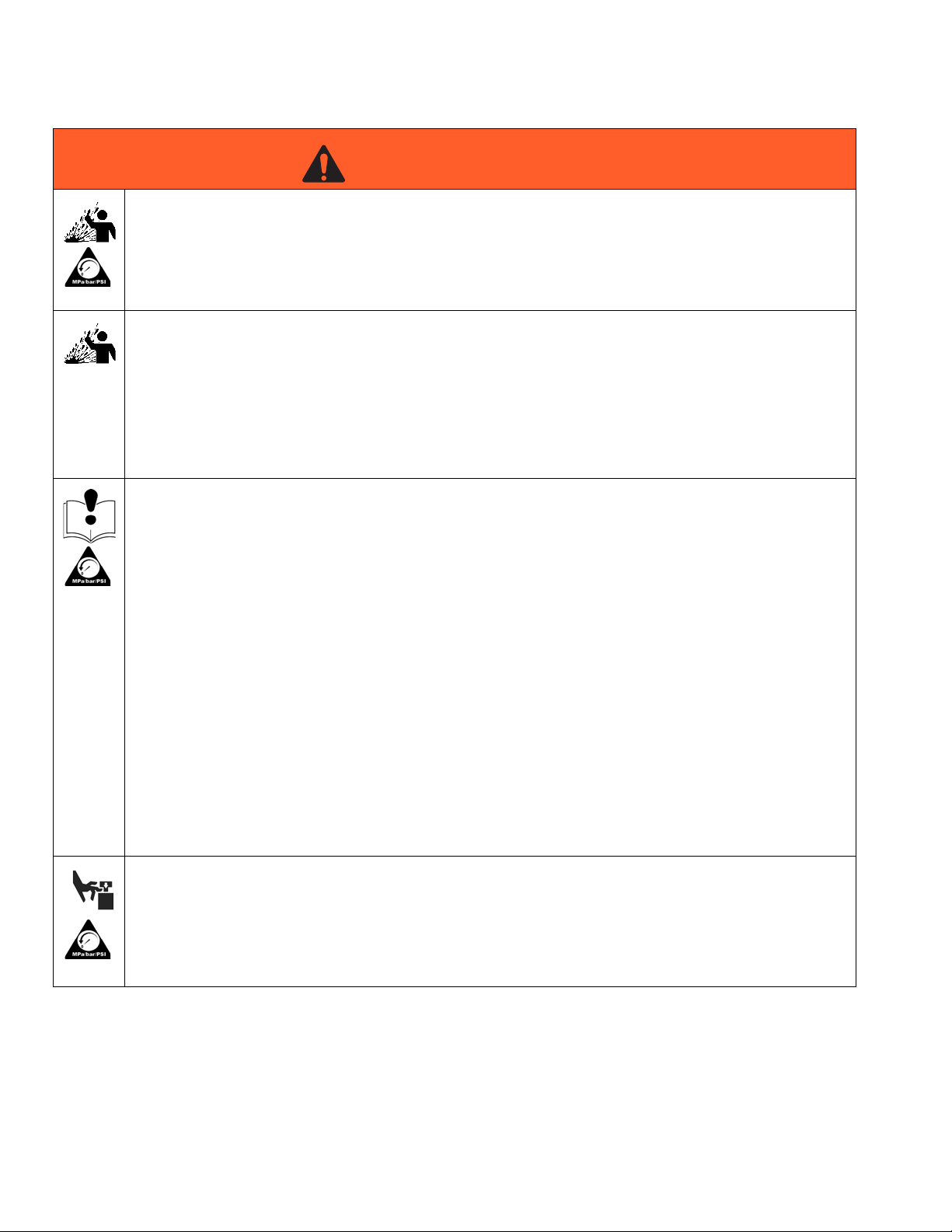
FIRE AND EXPLOSION HAZARD
When flammable fluids are present in the work area, such as gasoline and windshield wiper fluid, be
aware that flammable fumes can ignite or explode. To help prevent fire and explosion:
• Use equipment only in well ventilated area.
• Eliminate all ignition sources, such as cigarettes and portable electric lamps.
• Keep work area free of debris, including rags and spilled or open containers of solvent and gasoline.
• Do not plug or unplug power cords or turn lights on or off when flammable fumes are present.
• Ground all equipment in the work area.
• Use only grounded hoses.
• Stop operation immediately if static sparking occurs or you feel a shock. Do not use equipment
until you identify and correct the problem.
• Keep a working fire extinguisher in the work area.
SKIN INJECTION HAZARD
High-pressure fluid from dispensing device, hose leaks, or ruptured components will pierce skin. This
may look like just a cut, but it is a serious injury that can result in amputation. Get immediate surgical
treatment.
• Do not point dispensing device at anyone or at any part of the body.
+
• Do not put your hand over the fluid outlet.
• Do not stop or deflect leaks with your hand, body, glove, or rag.
• Follow the Pressure Relief Procedure when you stop dispensing and before cleaning, checking, or
servicing equipment.
• Tighten all fluid connections before operating the equipment.
• Check hoses and couplings daily. Replace worn or damaged parts immediately.
332514J 3
Page 4
Warnings
WARNINGWARNINGWARNING
WARNING
PRESSURIZED EQUIPMENT HAZARD
Over-pressurization can result in equipment rupture and serious injury.
• A pressure relief valve is required at each pump outlet.
• Follow Pressure Relief Procedure in this manual before servicing.
PRESSURIZED ALUMINUM PARTS HAZARD
Use of fluids that are incompatible with aluminum in pressurized equipment can cause serious chemical
reaction and equipment rupture. Failure to follow this warning can result in death, serious injury, or property damage.
• Do not use 1,1,1-trichloroethane, methylene chloride, other halogenated hydrocarbon solvents or
fluids containing such solvents.
• Many other fluids may contain chemicals that can react with aluminum. Contact your material supplier for compatibility.
EQUIPMENT MISUSE HAZARD
Misuse can cause death or serious injury.
• Do not operate the unit when fatigued or under the influence of drugs or alcohol.
• Do not exceed the maximum working pressure or temperature rating of the lowest rated system
component. See Technical Data in all equipment manuals.
• Use fluids and solvents that are compatible with equipment wetted parts. See Technical Data in all
equipment manuals. Read fluid and solvent manufacturer’s warnings. For complete information
about your material, request MSDS from distributor or retailer.
• Turn off all equipment and follow the Pressure Relief Procedure when equipment is not in use.
• Check equipment daily. Repair or replace worn or damaged parts immediately with genuine manufacturer’s replacement parts only.
• Do not alter or modify equipment. Alterations or modifications may void agency approvals and create
safety hazards.
• Make sure all equipment is rated and approved for the environment in which you are using it.
• Use equipment only for its intended purpose. Call your distributor for information.
• Route hoses and cables away from traffic areas, sharp edges, moving parts, and hot surfaces.
• Do not kink or over bend hoses or use hoses to pull equipment.
• Keep children and animals away from work area.
• Comply with all applicable safety regulations.
MOVING PARTS HAZARD
Moving parts can pinch, cut or amputate fingers and other body parts.
• Keep clear of moving parts.
• Do not operate equipment with protective guards or covers removed.
• Pressurized equipment can start without warning. Before checking, moving, or servicing equipment,
follow the Pressure Relief Procedure and disconnect all power sources.
4 332514J
Page 5
Warnings
WARNINGWARNINGWARNING
WARNING
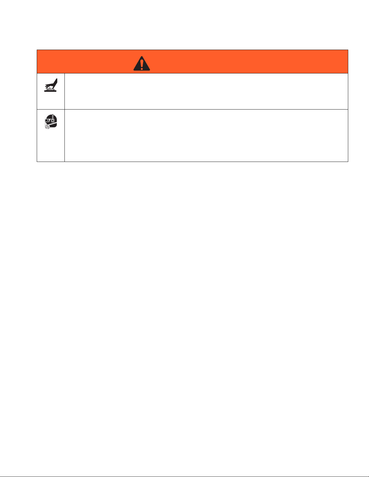
BURN HAZARD
Equipment surfaces and fluid that’s heated can become very hot during operation. To avoid severe
burns:
• Do not touch hot fluid or equipment.
PERSONAL PROTECTIVE EQUIPMENT
Wear appropriate protective equipment when in the work area to help prevent serious injury, including
eye injury, hearing loss, inhalation of toxic fumes, and burns. This protective equipment includes but is
not limited to:
• Protective eyewear, and hearing protection.
• Respirators, protective clothing, and gloves as recommended by the fluid and solvent manufacturers.
332514J 5
Page 6

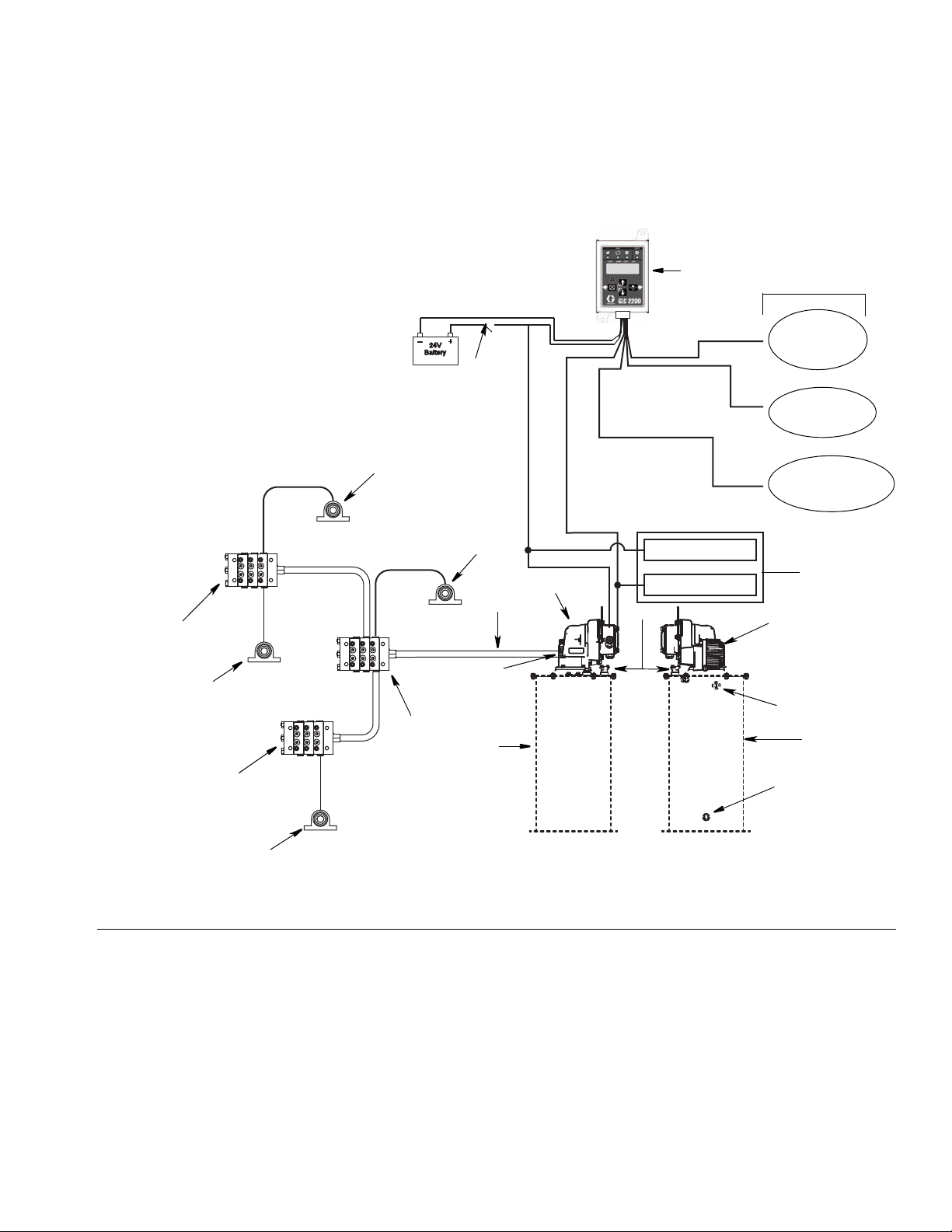
Typical Installation: Injector System
E
D
C
F
B
H
K
G
FrontBack
Low Reservoir
Level Switch
(Level Indicator,
optional)
Pressure Switch
for System Control
Remote Alarm Device
(Light or Horn)
(user provided
Controller
Capabilities
J
K
L
A
M
Motor Control
Board
Pump Power
Pump Signal
Vent Valve
Typical Installation: Injector System
The installation shown in below is only a guide for selecting and installing system components. Contact your Graco
distributor for assistance in planning a system to suit your needs.
FIG. 1
Key:
A Lubricant output connection
B Pump
C Ignition switch*
D High-pressure lubricant supply lines*
E Injector banks*
F Lubrication controller*
G Fill port (for reference only; non-tube-in-tube models only)
H Overflow port (for reference only)
J Breather (for reference only)
K Reservoir / Tank
L Vent Valve (for reference only)
M Motor
*User provided
6 332514J
Page 7
Typical Installation: Series Progressive System
E
D
C
F
B
H
K
G
FrontBack
Low Reservoir
Level Switch
(Level Indicator,
optional)
Pressure Switch
for System Control
Remote Alarm Device
(Light or Horn)
(user provided
Controller
Capabilities
J
K
A
M
L
N
N
L
N
N
Motor Control
Board
Pump Power
Pump Signal
Typical Installation: Series Progressive System
The installation shown below is only a guide for selecting and installing system components. Contact your Graco distributor for assistance in planning a system to suit your needs.
FIG. 2
Key:
A Lubricant output connection
B Pump
C Ignition switch*
D High-pressure lubricant supply lines*
E Primary metering device*
F Lubrication controller*
G Fill port (for reference only; non-tube-in-tube models only)
H Overflow port (for reference only)
J Breather (for reference only)
K Reservoir / Tank (for reference only)
L Secondary metering device
M Motor
N Bearing
*User provided
332514J 7
Page 8

Installation
a
b
c
126
128
Installation
Pressure Relief
Follow the Pressure Relief Procedure whenever
you see this symbol.
This equipment stays pressurized until pressure is
manually relieved. To help prevent serious injury
from pressurized fluid, such as skin injection,
splashing fluid and moving parts, follow the Pressure
Relief Procedure when you stop dispensing and
before cleaning, checking, or servicing the
equipment.
To relieve pressure in the system, use two wrenches
working in opposite directions on pump outlet fitting to
slowly loosen fitting only until fitting is loose; no more
lubricant or air is leaking from fitting as shown in F
IG. 3.
• Install tank / reservoir cover on tank / reservoir.
Tighten screws to secure cover to tank / reservoir.
1. Remove pump mounting screws (a) and washers
(b) from tank / reservoir cover. Save these parts.
Gasket (c) should not be removed from the cover.
These parts will be used to install the pump to the
tank / reservoir cover for reassembly.
FIG. 4: 120 Pound Cover Shown
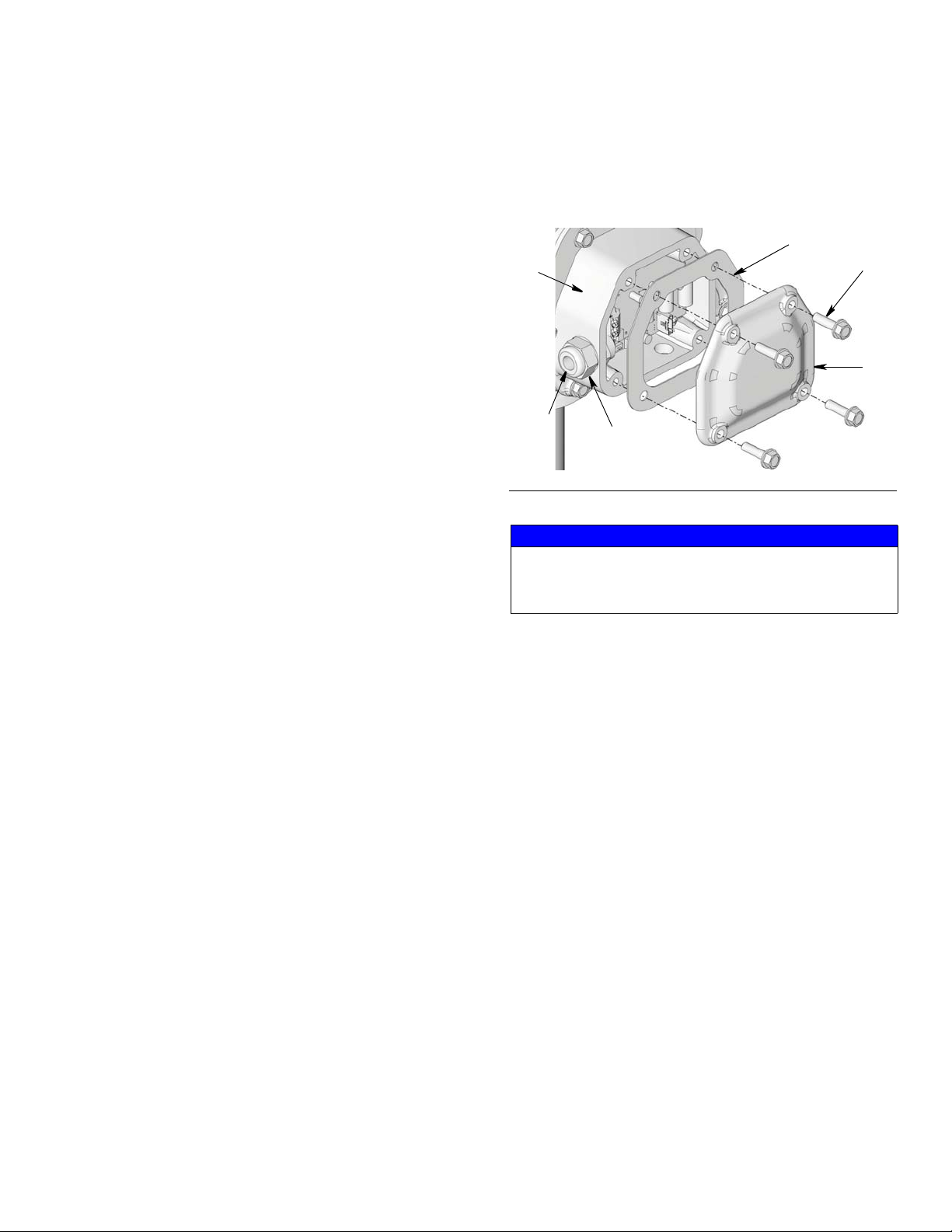
2. Loosen bolts (128) and remove cover (126) from
Dyna-Star pump (F
IG. 5).
FIG. 3
Pump Module
Reference numbers used in the following instructions
refer to Parts, page 35. Upper case reference letters
used in the following instructions refer to Typical Installation Drawings provided on pages 6 and 7.
NOTE:
• Tank / reservoir covers and reservoirs are available
from Graco. Contact your Graco Distributor or
Graco Customer Service for assistance ordering
these parts. See Parts, page 38 for a complete list
of accessories.
• Before installing pump on tank / reservoir, use bolts
to secure tank / reservoir to it’s installation location.
8 332514J
FIG. 5
3. Remove protective cap (d) from pump down-tube
(208) (F
IG. 6). Discard cap. You will not use it again.
Page 9

208
d
c
e
e
e
FIG. 8
a
b
J
115
133
Installation
FIG. 6
4. Verify gasket (c) is in place on top the reservoir
cover, laying flat and that the holes (e) in the gasket
align with the holes in the cover (F
IG. 7).
FIG. 7
HEAVY EQUIPMENT HAZARD
Lifting or moving heavy equipment incorrectly can
cause serious injury. To avoid serious injuries, such as
muscle strain or back injuries, when moving pump
always use a lifting aid secured to the pump lift ring .
See Technical Data, included in the pump instruction
manual for pump weight information.
5. Install pump down-tube through opening in the center of the gasket and tank / reservoir cover and into
tank / reservoir.
6. Align holes in pump base with holes in tank / reservoir cover (F
IG. 8). Securely fasten pump to tank /
reservoir cover using screws (a) and washers (b)
removed in Step 1, page 8.
NOTE: When the pump is correctly installed on the
Graco tank, the breather (J) will be below the control
box (115) as shown in F
IG. 9.
FIG. 9
NOTICE
To prevent damage to the unit:
• Check breather (J) vent for proper operation
before filling reservoir.
• Open overflow port (H) before filling reservoir to
visually inspect lubrication level.
• Do not fill reservoir beyond overflow port (H).
• Do not use breather vent as a port to fill
reservoir.
7. Reinstall cover (126) using bolts (128). Use a
wrench to tighten bolts securely (F
IG. 10).
332514J 9
Page 10

Wiring
126
128
0
D
Wiring
Grounding
The equipment must be bonded (grounded)
directly to the truck. Grounding reduces the risk of
static shock due to static build up on the
equipment.
FIG. 10
8. Connect the timer/controller (F) (user supplied, if
used).
9. Connect High Pressure Lubricant Supply Line (D) to
the Lubricant Output Connection (0) (F
Vent Valve or Manifold.
NOTE: The High Pressure Lubricant Supply Line
(D) is disconnected from the Lubricant Output Connection (0) during Priming, page 15.
FIG. 11: Lubricant Outlet Connection
IG. 11) on the
System Configuration and Wiring
NOTE: Cable wiring harness kits are available from
Graco. See Parts page 38 for a complete list of available
kits.
Fuses
NOTICE
Fuses (user supplied) are required on all models. To
avoid equipment damage:
• Never operate the Dyna-Star Pump models without
a fuse installed.
• A fuse of the correct voltage and amperage must
be installed in line with the power entry to the system. Graco recommends using 35A fuses.
10 332514J
Page 11
Wiring
116
120
SR
119
115
CN
Installation Instructions
Reference numbers used in the following instructions
refer to Parts, page 36.
1. Remove screws (116), cover (120) and gasket (119)
to access motor lead wires (F
2. Feed the incoming power source wires through the
strain relief body (SR) and into the gear housing
(F
IG. 12).
a. Tighten the strain relief body (SR) to the gear
housing (115) to 5.1 ft.-lbs (7.0 N.m).
b. Tighten the compression nut (CN) to 3.7 ft.-lbs
(5.0 N.m).
NOTE: See Technical Data, page 39 for wire O.D. specifications to verify correct cable is used.
3. Make all source to input power connections (A and
B, page 13) and pump control connections (C and
D, page 13). Refer to F
wiring diagrams and Control Board diagram, page
13.
IG. 12).
IG. 13 or FIG. 14, page 12 for
4. Route wires into box. Replace gasket (119) cover
(120) and screws (116), being careful not to pinch
any wires. Tighten bolts securely. Torque bolts to
17-19 ft.-lbs (23-26 N.m).
FIG. 12
NOTICE
To avoid equipment damage, remove power before
switching modes from signal to power or power to signal.
332514J 11
Page 12

Wiring
35 A
18 - 32VDC
5 - 32VDC
Sig In
Sig In
SigPwr
Electric
Vent *
Valve
Motor Control Board
Lubrication
Controller
Pump Output
Pump Output
40A Relay
Sig In
Sig In
SigPwr
35 A
Pump Output
Pump Output
18 - 32VDC
5 - 32VDC
Electric
Vent *
Valve
Motor Control Board
Lubrication
Controller
24 VDC With Signal Input
FIG. 13: Pump control switch shown in signal mode
*A Vent Valve is only used in an injector-based system.
24 VDC With External Relay
FIG. 14: Pump controls switch shown in power mode
*A Vent Valve is only used in an injector-based system.
12 332514J
Page 13

DC Models - Motor Control Board
MAX
MAX
MIN
MIN
SPEED
CURRENT
SIGPWR
BLUE
YELLOW
GREEN
HJ
A
B
C
D
F E
G
K
L
M
N
Wiring
FIG. 15
Key
A - (Negative) Power Input
B + (Positive) Power Input
C Turn On Signal
D Turn On Signal +
E Red (Fault) LED - Blinks type of fault (See Fault Table)
F Green (Power) LED -
• Blinks: Power ON, Pump running
• Solid: Power/Pump OFF
G Current Control Potentiometer (Minimum: Turn Knob
Counter-Clockwise / Maximum: Turn Knob Clockwise)
H Flow Control Potentiometer (Minimum: Turn Knob
Counter-Clockwise / Maximum: Turn Knob Clockwise)
J Pump Control Switch*
• PWR - Turns pump on when power is applied
• SIG - Turns pump on when voltage is applied to:
- SIG IN
K Blue Motor Wire Connection
L Yellow Motor Wire Connection
M Green Motor Wire Connection
N J5 Connector - Motor Hall Cable Connector
332514J 13
- SIG IN +
Fault Table: Red LED (E)
Fault Blinks
Over Current 1
Locked Rotor 2
Low or High Voltage 3
High Motor temp 4
Missing Temp Sensor 5
High Board Temp 6
Bad Hall Cable 7
*NOTE: Be sure power to pump is OFF before switching
between the PWR and SIG modes.
Page 14

Wiring
2
30
23
20
10
4
40
30
in3/min.
2
30
23
10
5
2
20
15
in3/min.
Current Control and Flow Motor Control Settings
Current and Flow control are adjusted on the Motor Control Board using the Current Control Potentiometer Knob (G)
and the Flow Control Potentiometer Knob (H) (page 13). Turn knob to clockwise to increase setting value. Turn knob
counter-clockwise to decrease setting value.
The Current Control knob (G) governs flow. The Current setting has precedence over the Flow Rate setting. You may
be limited in achievable Flow Rate by the Current setting.
See Performance Charts, page 41 for Flow Rate and Current information.
NOTE: Values are based on lab test conditions at ambient temperature 72°F (22°C) with an input voltage of 24V.
Actual results may very and should be verified in the application.
HF Current HF Flow
15
8
Amps
HP Current HP Flow
15
8
Amps
14 332514J
Page 15

Operation
Upper case letters used in the following instructions
refer to Typical Installation provided on page 6 or 7.
• Be sure unit is securely mounted and grounded
before operation.
• Do not lift pressurized equipment.
Priming
Operation
COMPONENT RUPTURE HAZARD
The maximum working pressure of each component
in the system may not be the same. Over pressurizing any component can result in rupture, fire, explosion, property damage and serious injury.
To reduce the risk of over pressurizing any component in the system, be sure you know the maximum
working pressure of each component. Never exceed
the maximum working pressure of the lowest rated
component in the system.
1. After reservoir/tank is completely filled, remove high
pressure lubricant supply line (D) from the outlet.
2. Connect power to pump.
3. Start pump and run pump until all air has been
expelled and fluid flow is continuous.
4. Reconnect the high pressure lubricant supply line
(D) to outlet.
Fill Reservoir
Do not insert finger into the overflow port while filling
a reservoir equipped with a follower plate. Injury or
amputation could result.
NOTICE
To prevent damage to the unit:
• Check breather (J) vent for proper operation
before filling reservoir.
• Open overflow port (H) before filling reservoir to
visually inspect lubrication level.
• Do not fill reservoir beyond overflow port (H).
• Do not use breather vent as a port to fill
reservoir.
Regulate pressure to the pump so that no fluid line,
component or accessory is over pressurized.
NOTICE
Never allow pump to run dry of the fluid being
pumped. Running a pump dry can damage the
pump.
Shutdown
For normal system shut down, disconnect power to
lubricator controller (F) and pump (B) to control board.
332514J 15
Page 16

Troubleshooting
Troubleshooting
Problem Cause Solution
Pump not powering ON, green LED
is not ON
Pump is powered on, green LED is
ON but pump is not cycling
Pump is powered on, green LED is
blinking, pump cycles continuously
instead of turning OFF
Pump is cycling but there is no
lubricant output from the outlet
Pump is cycling slow
Pump is cycling, there is output of
fluid at the outlet, pump pressure is
not building
Wiring not done correctly, polarity is
wrong or loose wire(s)
Fuse not in place or fuse is faulty Check fuse rating. If incorrect fuse is
Lubrication controller is in OFF mode Set lubrication controller to correct
Motor is not wired properly to control
board
Pump control switch (J) is set to
PWR mode. Pump cycling is not
controlled by signal output
Lubricant level in tank/reservoir is too
low
Damaged tank or reservoir Replace tank/reservoir.
Pump is cavitating
Pump seals are worn or damaged Replace pump seals. See Seal
Current Control Potentiometer Knob
(G) on motor control board is set too
low
Flow Control Potentiometer Knob (H)
on motor control board is set too low
Leakage in a lubrication line Check lubrication line for leakage.
Pump seals are worn or damaged Replace pump seals. See Seal
Check wire connections. Verify they
are all tight. Correct polarity.
used, install fuse of the correct
amperage.
lube cycle.
Connect wires to correct color
terminals.
Change pump control switch (J) to
signal mode (SIG).
Refill tank/reservoir.
Shake tank/reservoir to redistribute
grease.
Install a follower plate to help
distribute grease during pump
operation.
Replacement instructions, page 19.
Increase the current limit by turning
the Current Control Potentiometer
Knob (G), clockwise.
Increase the flow limit by turning the
Flow Control Potentiometer Knob
(H), clockwise.
Replace any lines that are leaking
and/or damaged.
Replacement instructions, page 19.
16 332514J
Page 17

Troubleshooting
Problem Cause Solution
Red fault LED (E) on control board,
blinking
Over current fault - 1 blink System pressure too high Reduce system pressure by installing
larger diameter lubrication tubes
Current Control Potentiometer Knob
(G) on motor control board is set too
low
Increase the current limit by turning
the Current Control Potentiometer
Knob (G), clockwise.
System pressure too high Reduce system pressure by installing
larger diameter lubrication tubes
Current Control Potentiometer Knob
(G) on motor control board is set too
low
Increase the current limit by turning
the Current Control Potentiometer
Knob (G), clockwise.
Separate motor from pump and run
Motor is damaged
Locked rotor - 2 blinks
Pump lower is plugged
motor. If motor is damaged, replace
motor. See Motor Replacement
instructions, page 28.
Follow Seal Replacement instructions to disassemble pump lower.
Inspect and clean parts as needed
prior to using them for reassembly.
Replace all damaged and worn
parts. See Seal Replacement
instructions, page 19.
Low or high voltage - 3 blinks Faulty input line voltage Use a multi-meter to check input line
voltage measure 18-32 volts DC.
System pressure too high Reduce system pressure by installing
larger diameter lubrication tubes.
Current Control Potentiometer Knob
(G) on control board is set too low
Increase the current limit by turning
the Current Control Potentiometer
Knob (G), clockwise.
Separate motor from pump and run
Motor temperature is high - 4
blinks
Motor is damaged
motor. If motor is damaged, replace
motor. See Motor Replacement
instructions, page 28.
Motor control switch (J) is set to PWR
mode. Pump cycling is controlled by
Change motor control switch (J) to
signal mode (SIG).
signal output and pump is running
continuously
High duty cycle Reduce duty cycle.
Loose or damaged HALL sensor
cable
Missing temperature sensor blinks - 5 blinks
Motor is damaged
Verify HALL sensor cable is securely
attached. Tighten connection.
Replace damaged cable.
Separate motor from pump and run
motor. If motor is damaged, replace
motor. See Motor Replacement
instructions, page 28.
332514J 17
Page 18

Troubleshooting
Problem Cause Solution
Control board temperature is
high - 6 blinks
Loose or damaged HALL sensor
cable - 7 blinks
Motor runs but pump does not
Control board LED’s blink erratically
System pressure too high Reduce system pressure by installing
larger diameter lubrication tubes.
Current Control Potentiometer Knob
(G) on control board is set too low
Increase the current limit by turning
the Current Control Potentiometer
Knob (G), clockwise.
Separate motor from pump and run
Motor is damaged
motor. If motor is damaged, replace
motor. See Motor Replacement
instructions, page 28.
Motor control switch (J) is set to PWR
mode. Pump cycling is not controlled
Change motor control switch (J) to
signal mode (SIG).
by signal output and pump is running
continuously
High duty cycle Reduce duty cycle.
HALL sensor cable not securely
attached
Verify HALL sensor cable is securely
attached. Tighten connection.
Damaged HALL sensor cable Replace motor.
Motor shaft/gears are stripped or
damaged
Gear box is damaged. Replace
pump.
Damaged control board Replace motor control board. See
Motor Control Board Replacement
instructions, page 31.
18 332514J
Page 19

Repair
0
D
126
128
a
b
Repair
Seal Replacement
Kits 24T860 - HP Models or 24T861 - HF Models
• Reference numbers used in the following instruc-
tions refer to Parts pages beginning on page 35.
• Upper case letters used in the following instructions
refer to Typical Installation provided on page 6 or 7.
• Lower case letters used in the following instructions
refer to component parts or user provided parts.
• Unless otherwise noted, keep all parts for reassem-
bly. Inspect and clean parts as needed prior to using
them for reassembly.
• Use all new parts included in kit for reassembly.
Disassembly
1. Disconnect Dyna-Star pump from main power
source.
5. Loosen bolts (128) and remove cover (126) from
Dyna-Star pump (F
FIG. 17
6. Remove screws (a) and washers (b) holding
Dyna-Star Pump to cover and remove pump from
cover (F
table top protected with a drop cloth.
IG. 18). Place pump on a workbench or
IG. 17).
2. Relieve pressure (see Pressure Relief procedure,
page 8).
3. Disconnect Timer/Controller (F) (user supplied, if
used).
4. Disconnect High Pressure Lubricant Supply Line (D)
to the Lubricant Output Connection (0) (F
the Vent Valve or Manifold.
FIG. 16: Lubricant Outlet Connection
IG. 11) on
FIG. 18
332514J 19
Page 20

Repair
4
3
5
2
101
123
124
125
122
6
2
7. For Tube-In-Tube models only: Remove bolts (4)
holding tube (3) to pump adapter (2). Remove tube
and gasket (5) and set these parts aside to use for
reassembly (F
IG. 19).
FIG. 19
8. Observe location of priming rod (215) and shovel
piston (216) inside the shovel cylinder (208) (See
Pump Parts, page 38). If the piston is not located in
the lowest position inside the cylinder:
c. Remove screws (125) and washers (124) hold-
ing motor (123) to gear box housing (101) (F
IG.
20).
e. Use a screw driver to turn motor shaft clockwise
until shovel piston (216) is seated in the lowest
position inside the shovel cylinder (208).
NOTICE
Pump has a one way clutch. Do not use a power
screwdriver to turn shaft or not turn shaft
counter-clockwise. These actions could damage
pump/motor.
FIG. 21
f. Verify o-ring (122) is still in place and correctly
seated in motor (123) (F
IG. 20).
d. Remove motor.
FIG. 20
g. Reinstall motor (123) to gear housing box (101)
using screws (125) and washers (124). Use a
wrench to tighten screws securely. Torque to 12
- 14 ft lbs (16 - 19 N.m) (F
9. Remove screws (6) from pump adapter (2) (F
IG. 20).
IG. 22).
FIG. 22
20 332514J
Page 21

Repair
2
8
2
8
7
212
102a
102
212
8
2
9
8
10. Pull pump adapter (2) down to access retaining
spring (8) (F
IG. 23).
FIG. 23
11. Slide spring (8) out of groove (102a) in connecting
rod (102) to expose pump pin (7) (F
IG. 24). Push or
tap pump pin (7) out of hole.
12. Separate displacement rod (212) from connecting
rod (102) and separate these sections. Put section
(102) in a safe place. You will need it for reassembly. (F
IG. 25).
NOTE: Be careful when pulling these sections apart
that you do not lose spring (8).
FIG. 25
13. Remove spring (8) and two seals (9). Put spring in a
safe place to use it for reassembly. The seals (9)
can be discarded. Use the new seals included in the
kit for reassembly (F
IG. 26).
FIG. 24
FIG. 26
14. Secure pump adapter (2) section in a brass vise.
NOTE: To protect the outside surface of the pump,
place a rag around the pump body before putting
pump in vise jaws.
15. The pump cylinder is comprised of 3 separate sections. Separate the shovel cylinder section (208)
from the pump cylinder (204) first, using two pipe
332514J 21
Page 22

Repair
208
216
215
204
211a
211
209
204
215
205
215
217
206
204
213
214
207
2
rod assembly
wrenches, working in opposite directions to loosen
shovel cylinder. When cylinder (208) is loose
enough, use your hands to unscrew and remove it
from the other sections (F
V
IG. 27).
FIG. 27
16.
HP Pump: Use wrench on flats of priming rod (215)
and socket to loosen and remove shovel piston
(216) (F
IG. 27).
HF Pump:
a. Use wrench on flats of priming rod (215).
Remove hex nut (219).
b. Unscrew shovel (216) and remove it from prim-
ing rod (215).
18. Separate pump cylinder (204) from spacer cylinder
(205) using two strap wrenches, working in opposite
directions to loosen spacer cylinder. When cylinder
(204) is loose enough, use your hand to unscrew
and remove it from the other section (F
IG. 29).
FIG. 29
19. Remove intake seal (207) and seal (206). Discard
these parts. Use new parts included in the kit for
reassembly.
20. Use a hammer or rubber mallet to tap the rod
assembly out of the pump adapter (2) in the direction shown in F
IG. 30.
17. Use a wrench on the flats (211a) of seal retainer
(211) and a strap wrench working in the opposite
direction, on pump cylinder (204), to loosen and
remove adapter and o-ring (209) from pump cylinder (204) (F
IG. 28). Discard o-ring. Use the new
o-ring included in the kit for reassembly.
FIG. 28
FIG. 30
22 332514J
Page 23

21. Use a punch and hammer to tap out pins (217) hold-
215
217
213
214
217
212
201
2
2
202
212
ing the rod sections together (F
IG. 31). Use your
hands to unscrew shovel rod (215) and spacer rod
(212) from piston (213).
FIG. 31
Repair
FIG. 32
27. Use the displacement rod (212) to push the packing
u-cup (202) out of the pump adapter (2) in the direction shown in F
IG. 33. Discard u-cup (202). A new
one is included in the kit.
22. Remove piston seal (214) from piston (213). Discard piston seal (214) and pins (217). New replacement parts are included in the kit.
23. Visually inspect rod sections and the inside surface
of pump cylinder (204) to verify they are not bent or
damaged following disassembly. A pump with bent
and/or damaged parts will not hold pressure and/or
operate efficiently.
24. Separate spacer cylinder (205) from pump adapter
(2) using a strap wrench to loosen cylinder. When
cylinder (205) is loose enough, use your hands to
unscrew and remove it from the pump.
25. Remove gasket seal (206) from inside pump
adapter (2) if it did not come out with the spacer cylinder (205). Discard gasket seal. Use gasket seal
included in the kit for reassembly.
26. Use a socket to loosen hex nut (201) and remove it
from the pump adapter (2) (F
IG. 32).
FIG. 33
332514J 23
Page 24

Repair
2
202
lips
down
202
201
2
212
2
213
214
213a
Reassembly
NOTE:
• Before reassembly carefully clean and inspect all
parts and pump surfaces for scratches and damage.
A pump with damaged parts will not hold pressure
or operate efficiently.
• Use all new parts included in kit for reassembly.
1. Apply a thin layer of grease to the packing u-cup
(202).
2. Use a flat, blunt-end tool to seat u-cup (202), with
the lips facing down, into the pump adapter (2) (F
34).
NOTE: Do not damage u-cup seal on threads during
installation.
NOTICE
Sliding displacement rod (212) into the pump adapter
from the other side of the pump adapter (2) could
damage the throat seal (201), resulting in a poor seal
and fluid leakage during operation.
IG.
FIG. 35
5. Slide together piston rod (213) and piston seal (214)
(FIG. 36).
FIG. 36
FIG. 34
3. Install hex nut (201) inside pump adapter (2). Use a
wrench to tighten nut securely (F
IG. 34). Torque to
18-22 ft lbs (24 - 30 N.m)
4. Apply a thin layer of grease to the surface of displacement rod (212). Slide rod into the pump
adapter (2) in the direction shown in F
IG. 35 only.
6. Thread piston rod (213) into end of displacement
rod (212). Hand tighten the two pieces together
securely, ending with hole (213a) (F
with hole (212a) (F
IG. 37).
IG. 36) aligned
24 332514J
Page 25

Repair
212a
212
217
217
213b
215a
215
213
206
205
2
207
206
204
lips up
214
7. Install pin (217) through the aligned holes [(213a
(F
IG. 36) and 212a (FIG. 37)]. Support rods (212 and
213) as needed to ensure the rods do not bend. Use
a pick and hammer to seat the pin inside the rods.
NOTE: Be sure pin is centered in the hole. A pin
that is not entirely seated could scratch the bore of
the pump cylinder (204) during pump operation; preventing pressure from building and causing fluid to
leak.
FIG. 37
8. Thread priming rod (215) into end of piston rod
(213). Hand tighten the two pieces together
securely, ending with hole (215a) aligned with hole
(213b) (F
IG. 38).
9. Install pin (217) through the aligned holes [215a and
213b (F
IG. 38)]. Support rods (215 and 213) as
needed to ensure the rods do not bend. Use a pick
and hammer to seat the pin inside the rods.
NOTE: Be sure pin is centered in the hole. A pin
that is not entirely seated could scratch the bore of
the pump cylinder (204) during pump operation; preventing pressure from building and causing fluid to
leak.
10. Apply a thin layer of grease around gasket (206).
Install gasket over end of spacer cylinder (205).
Slide cylinder over rod assembly as shown in F
IG.
39. Thread end of cylinder into bottom of pump
adapter (2). Use a pipe wrench to turn cylinder until
tightened securely. Torque to 45 - 55 ft lbs (61-74
N.m).
FIG. 39
11. Apply a thin layer grease to seal (206) and install
around pump cylinder (204) (F
IG. 40).
12. Apply a thin layer of grease to piston seal (214).
13. Thread pump cylinder (204) to spacer cylinder
(205). Use a wrench to tighten securely. Torque to
45-55 ft lbs (61-74 N.m).
14. Apply a thin layer of grease to intake seal (207) and
install seal with lips facing up inside pump cylinder
(204) as shown in F
IG. 40.
FIG. 38
FIG. 40
332514J 25
Page 26

Repair
211
209
204
211a
208
216
215
204
9
2 212
8
212a
2a
8
2
212
7
102b
102
102a
15. Apply a thin layer of grease to o-ring (209) and
install around the seal retainer (211) (F
IG. 41).
16. Thread seal retainer (211) to pump cylinder (204)
with the seal end installed inside the pump cylinder
as shown in F
IG. 41. Use a wrench on the nut (211a)
to tighten adapter nut securely. Torque to 18-22 ft
lbs (24 - 30 N.m).
FIG. 41
HF Pump:
a. Thread shovel piston (216) to the end of priming
rod (215). Hand tighten.
b. Tighten nut using a socket wrench on nut (219)
and a second wrench on flats of priming rod
(215) turning in the opposite direction.
17. Thread shovel cylinder (208) to pump cylinder (204)
(F
IG. 42). Use a wrench to tighten securely.
18. Push displacement rod assembly up until displacement rod (212) is extending out the top of the pump
adapter (2) as shown in F
IG. 43.
19. Apply a thin layer of grease to gasket seals (9).
Install seals in pump adapter (2) as shown in F
IG. 43
HP Pump: Thread shovel piston (216) to the end of
priming rod (215). Use a socket wrench on piston
(216) and wrench on the flats of priming rod (215) to
securely tighten shovel piston (F
IG. 42). Torque to
145 to 155 in. lbs (16 - 17 N.m).
NOTE: Be careful when tightening the nut that the
rod assembly does not twist and break the support
pins (217) or bend any of the rod sections.
FIG. 42
FIG. 43
20. Place spring (8) over the end of displacement rod
(212) as shown in F
IG. 44.
26 332514J
FIG. 44
Page 27

Repair
9
103b
103
2
6
2
pu
4
5
2
3
a
b
21. Remove pump assembly from vise. Align hole
(212a) in displacement rod (212) (F
necting rod hole (102b) (F
IG. 44). Insert pin (7)
IG. 43) with con-
through hole.
22. Slide spring (8) over pin (7) to secure pin in place.
Seat spring in groove (102a) in connecting rod (102)
to prevent it from moving during pump operation.
23. Align the two gasket seals (9) in pump adapter (2)
with two holes (103b) in gear box pump bracket
(103). Push the pump lower and pump assembly
together (F
IG. 45).
25. For Tube-In-Tube models only: Install gasket (5)
and Tube-In-Tube (3). Secure Tube-In-Tube to
pump adapter (2) using screws (4). Use a socket to
tighten bolts securely (F
IG. 47). Torque to 7-9 ft lbs
(9-12 N.m).
NOTE: Tube-In-Tube Replacement Kits 24T863 for
60 pound pumps, 24T864 for 90 pound pumps, and
24T865 for 400 pound pumps are available from
Graco. See Parts, page 38 for information about
ordering these kits or contact your Graco Distributor
or Graco Customer Service.
FIG. 47
26. Align holes in pump base with holes in tank / reservoir cover. Securely fasten pump to tank / reservoir
FIG. 45
cover using screws (a) and washers (b) (F
IG. 48).
24. Secure pump adapter (2) to pump upper (pu) using
screws (6). Use a socket to tighten screws securely
(F
IG. 46). Torque to 7-9 ft lbs (9-12 N.m).
Be careful when installing pump to base that wire har-
NOTICE
ness to motor is not caught between the pump and the
hole on top of the reservoir. If the wire harness is
caught between the pump and reservoir, the wires
could be damaged.
FIG. 46
332514J 27
FIG. 48
Page 28

Repair
J
115
126
128
0
D
0
D
NOTE: When the pump is correctly installed, the
breather (J) will be below the control box (115) as
shown in F
IG. 49.
FIG. 49
27. Reinstall cover (126) using bolts (128). Use a
wrench to tighten bolts securely (F
IG. 50).
Motor Replacement: Kit 24T862
• Reference numbers used in the following instruc-
tions refer to Parts pages beginning on page 35.
• Upper case letters used in the following instructions
refer to Typical Installation provided on page 6 or 7.
• Lower case letters used in the following instructions
refer to component parts or user provided parts.
• Unless otherwise noted, keep all parts for reassem-
bly. Inspect and clean parts as needed prior to using
them for reassembly.
• Use all new parts included in kit for reassembly.
Disassembly
1. Disconnect Dyna-Star pump from main power
source.
FIG. 50
28. Connect the timer/controller (F) (user supplied, if
used).
29. Connect High Pressure Lubricant Supply Line (D) to
the Lubricant Output Connection (0) (F
IG. 51) on the
Vent Valve or Manifold.
FIG. 51: Lubricant Outlet Connection
30. Connect power to pump.
31. See Operation instructions for pump priming and
reservoir filling instructions, page 15.
2. Relieve pressure (see Pressure Relief procedure,
page 8).
3. Disconnect Timer/Controller (F) (user supplied, if
used).
4. Disconnect High Pressure Lubricant Supply Line (D)
to the Lubricant Output Connection (0) (F
IG. 52) on
the Vent Valve or Manifold.
FIG. 52: Lubricant Outlet Connection
28 332514J
Page 29

Repair
116
120
119
134
117a
115
134
135
a
115
101
123
124
125
122
5. Remove screws (116) from motor control box cover
(120) and remove cover and gasket (119) (F
IG. 53).
FIG. 53
6. Remove nuts (134) as shown in F
IG. 54. Remove
washers (135) and motor wires from terminals.
Save these parts to use them for reassembly.
7. Disconnect sensor cable (117a) from motor control
board (F
IG. 54).
8. Use a wrench to loosen strain relief (a) and remove
wiring harness from housing (F
IG. 55).
FIG. 55
9. Remove screws (125) and washers (124) holding
motor (123) to gear box housing (101). Remove
motor. Verify o-ring (122) was removed with motor.
(F
IG. 56)
If o-ring (122) is still inside the gear box housing
(101), remove it.
Discard these parts in accordance with all safety
regulations.
FIG. 56
FIG. 54
332514J 29
Page 30

Repair
101
123
124
125
122
115a
115
a
CN
SR
134
117a
115
134
135
Reassembly
NOTE:
• Use all new parts included in kit for reassembly.
1. Apply a thin coating of Gleitmo 585K grease to shaft
of the new motor.
2. Apply a thin layer of grease to o-ring (122). Install
o-ring in motor (123) (F
FIG. 57
3. Install new motor (123) using screws (125) and
washers (124) (F
screws securely. Torque to 17-19 ft lbs (23 - 25
N.m).
IG. 57).
IG. 57). Use a wrench to tighten
5. Match green, yellow and blue wires to terminals of
same color (written on the motor control board).
Secure wires to terminals using washers and nuts
(134 and 135) (F
IG. 59). Torque to 8-10 in. lbs (0.9 -
1.1 N.m).
4. Feed motor wire harness (a) through strain relief
opening (115a) in housing (115) (F
IG. 58).
Thread strain relief body (SR) into opening (115a).
Tighten to 3.5 ft.-lbs (4.7 N.m). Tighten coupling nut
(CN) to 2.0 ft.-lbs (2.7 N.m).
FIG. 59
6. Connect sensor cable (117a) (F
IG. 59).
7. Replace control board gasket (119) and cover (120)
with screws (116) being careful not to pinch any
FIG. 58
30 332514J
Page 31

Repair
116
120
119
0
D
0
D
wires. Tighten screws securely. Torque to 17-19 ft
lbs (23 -25 N.m).
FIG. 60
8. Connect the timer/controller (F) (user supplied, if
used).
9. Connect High Pressure Lubricant Supply Line (D) to
the Lubricant Output Connection (0) (F
Vent Valve or Manifold.
IG. 61) on the
Motor Control Board Replacement: Kit 24T867
• Reference numbers used in the following instruc-
tions refer to Parts pages beginning on page 35.
• Upper case letters used in the following instructions
refer to Typical Installation provided on page 6 or 7.
• Lower case letters used in the following instructions
refer to component parts or user provided parts.
• Unless otherwise noted, keep all parts for reassem-
bly. Inspect and clean parts as needed prior to using
them for reassembly.
• Use all new parts included in kit for reassembly.
Disassembly
1. Disconnect Dyna-Star pump from main power
source.
FIG. 61: Lubricant Outlet Connection
10. Connect power to pump.
11. See Operation instructions for pump priming and
reservoir filling instructions, page 15.
2. Relieve pressure (see Pressure Relief procedure,
page 8).
3. Disconnect Timer/Controller (F) (user supplied, if
used).
4. Disconnect High Pressure Lubricant Supply Line (D)
to the Lubricant Output Connection (0) (F
the Vent Valve or Manifold.
FIG. 62: Lubricant Outlet Connection
IG. 62) on
332514J 31
Page 32

Repair
116
120
119
134
117a
115
134
135
A
B
C
D
117a
118
117
115
5. Remove screws (116) from motor control box cover
(120) and remove cover and gasket (119) (F
IG. 63).
FIG. 63
6. Remove nuts (134) as shown in F
IG. 64. Remove
washers (135) and motor wires from terminals.
7. Disconnect sensor cable (117a) from motor control
board (F
IG. 65).
8. Disconnect source to power input (A and B) and
pump control connections (C and D) (See F
IG. 65
and Control Panel, page 13).
FIG. 64
FIG. 65
9. Remove screws (118) securing motor control board
(117) to housing (115) (F
IG. 66).
FIG. 66
10. Remove motor control board from housing and dispose in accordance with all safety regulations.
32 332514J
Page 33

Repair
118
117
115
A
B
C
D
134
117a
115
134
135
Reassembly
NOTE:
• Use all new parts included in kit for reassembly.
1. Install new motor control board (117) in housing
(115) using screws (118) (F
in. lbs (0.9 - 1.1 N.m).
IG. 67). Torque to 8 - 10
3. Match green, yellow and blue wires of motor to terminals of same color (written on the control board).
Secure wires to terminals using washers (135) and
nuts (134) (F
IG. 59). Torque to 8 - 10 in. lbs (0.9 -
1.1 N.m).
FIG. 67
2. Connect source to power input (A and B) and pump
signal connections (C and D) (F
IG. 65 and A,B,C,D,
page 13). Torque to 5.5 - 7 in. lbs (0.62 - 0.79 N.m).
FIG. 69
4. Connect sensor cable (117a) (F
IG. 69).
FIG. 68
332514J 33
Page 34

Repair
116
120
119
0
D
5. Replace motor control board gasket (119) and cover
(120) with screws (116) (F
IG. 70) being careful not
to pinch any wires. Tighten screws securely. Torque
to 17 - 19 ft lbs (23 - 25 N.m).
FIG. 70
6. Connect the timer/controller (F) (user supplied, if
used).
7. Connect High Pressure Lubricant Supply Line (D) to
the Lubricant Output Connection (0) (F
IG. 71) on the
Vent Valve or Manifold.
FIG. 71: Lubricant Outlet Connection
8. Connect power to pump.
9. See Operation instructions for pump priming and
reservoir filling instructions, page 15.
34 332514J
Page 35

Parts List
1
3
5
4
6
8
7
9
13
12
11
14
16
18
19
15
2
30
29
31/32
33
Main Assembly All Models
Parts List
Ref.
No. Part No. Description Qty
1 BOX, gear, model (page 36)
2 24T897 KIT, adapter, pump, HP models
24T898 KIT, adapter, pump, HF models
3 TUBE-IN-TUBE, 60#, includes 4,
model 77X001, 77X011
TUBE-IN-TUBE, 120#, includes 4,
model 77X002, 77X012
TUBE-IN-TUBE, 400#, includes 4,
model 77X003, 77X013
4 SCREW, shcs M6 x 25, models
77X001, 77X002 and 77X003
5 GASKET, fill tube flange, models
77X001, 77X002, 77X003, 77X011,
77X012, 77X013
6 SCREW, shcs, M6-1.0X90 SST
7 15F856 PIN, pump
8 119778 SPRING, retaining
9
†
11
12
@
13
@ SCREW, cap, models 77X011,
14 LABEL, name, serial
15
@
16 16V999 VALVE, pressure relief, 5000 psi
115122@VALVE, pressure relief, 4000 psi (27.6
18 77X540 KIT, vent valve, also includes 12, 13,
19 24T862 KIT, motor replacement
16U728 LABEL, safety, warning
29
15H108 LABEL, safety, pinch
30
31 = CABLE, gland
32 = O-RING, M25
33 ASSEMBLY, pump lower (see page
GASKET, seal
ADAPTER, outlet, models 77X000,
77X001, 77X002, 77X003, 77X014,
77X015, 77X016
O-RING, -014 FKM 75 Duro
SCREW, cap, models 77X000,
77X001, 77X002, 77X003, 77X014,
77X015, 77X016
77X012, 77X013, included in kit
77X540
PLUG, pipe
(34.47 MPa, 344 bar), models
77X000, 77X001, 77X002, 77X003,
MPa, 276 bar), models 77X011,
77X012, 77X013, 77X014, 77X015,
77X016
15, 16, 17; included with models
77X011, 77X012, 77X013 only. Can
be added to other models
37 and 38)
1
1
1
1
1
1
4
1
4
1
1
2
1
2
3
3
1
1
1
1
1
1
1
2
1
1
1
Replacement Danger and Warning labels, tags, and cards
are available at no cost.
Included in Tube-In-Tube Kit 24T863 (60 pound),
24T864 (90 pound), 24T865 (400 pound).
Included in Seal Kit 24T860.
† Included in Seal Kit 24T861.
Included in Outlet Manifold Kit 16X171.
@Included in Vent Valve Kit 77X540.
= Included in Cable Gland Kit 77X533.
332514J 35
Page 36

Parts List
116
120
119
117
115
134
105
102
103
122
128
126
123
124
125
101
130
104
135
116
133
112
113
114
Gear Box
Ref.
No. Part No. Description Qty
101 HOUSING, gear box
102 ROD, connecting
103 BRACKET, gear box to pump
104 SCREW, M8
105 BOLT, M8
112 PACKING, o-ring
113 GEAR, first stage, w bearing
114 RING, retaining, internal
115 HOUSING, gear
116 $ SCREWS, M8
117 BOARD, control
118 SCREW, machine, phillips pan head
119 $ SEAL, control box cover
120 $ COVER, control box
1
1
1
2
2
1
1
1
1
11
1
4
1
1
122
123
124
125
126 COVER, shroud
128 BOLT, M6
133 RING, lift plate
134 NUT
135 WASHER
162841
PACKING, o-ring
MOTOR, 24VDC
WASHER, lock
SCREW, cap, hex head
Included in Control Board Kit 24T867.
Included in Shroud Kit 24T866.
Included in Motor Kit 24T862
$ Included in Motor Control Board Seal Kit 24U827
NOTE: Kit 24U827 only includes quantity 4 - #116
Screws.
1
1
3
3
1
2
1
3
6
36 332514J
Page 37

Parts List
HP Model Pump Lower: 16T857, 16N700, 16T757
Ref.
No. Part No. Description Qty
2 24T897 KIT, adapter, pump
201 15C530 NUT, retainer
202 PACKING, u-cup, throat, hp
204 15C537 CYLINDER, pump
205 16N718 CYLINDER, spacer, 35/60# (model
16T857)
16N686 CYLINDER, spacer, 90/120# (model
16N700)
16T753 CYLINDER, spacer, 400# (model
16T757)
206 GASKET, seal
207 SEAL, intake
208 192539 CYLINDER, shovel
209 O-RING
211 SEAL, retainer
212 16N719 ROD, displacement, 35/60# (model
16T857)
16N687 ROD, displacement, 90/120# (model
16N700)
16T754 ROD, displacement, 400# (model
16T757)
213 15G098 ROD, piston
214 SEAL, piston
215 15F296 ROD, shovel, 225, hp
216 16W249 PISTON, shovel, 50:1 hp
217 PIN, straight
Included in Seal Kit 24T860.
1
1
1
1
1
1
1
2
1
1
1
1
1
1
1
1
1
1
1
2
HF Model Pump Lower: 16T706, 16T821, 16T822
Ref.
No. Part No. Description Qty
2 24T898 KIT, adapter, pump
201 16F947 NUT, retainer
202 † PACKING, u-cup
204 16F774 CYLINDER, pump
205 16T704 CYLINDER, 90/120#, spacer (model
16T706)
16T818 CYLINDER, spacer, 400# (model
16T821)
16T819 CYLINDER, spacer, 35/60# (model
16T822)
206 † GASKET
207 † SEAL, intake
208 16F775 CYLINDER, shovel
209 † O-RING
211 † SEAL, retainer
212 16T703 ROD, displacement, 90/120# (model
16T706)
16T810 ROD, displacement, 400# (model
16T821)
16T811 ROD, displacement, 35/60# (model
16T822)
213 16F771 ROD, piston, 50:1
214 † SEAL, piston
215 16F943 ROD, priming
216 16F944 PISTON, shovel, 50:1 hp
217 † PIN, straight
219 16C022 NUT, hex
† Included in Seal Kit 24T861.
1
1
1
1
1
1
1
2
1
1
1
1
1
1
1
1
1
1
2
1
332514J 37
Page 38

Parts List
201
202
212
217
217
208
216
211
209
204
207
215
213
214
205
206
206
216
219
208
HF Models
HP Models
2
Pump Lower Parts Cable Harness Kits
Part No. Description
77X527 CABLE, power, series progressive system
only. Use with 77X528.
77X529 CABLE, power, injector system only. Use
with77X528.
77X528 CABLE, power, extension, 15 ft (4.6 m). Used
with 77X527 and 77X529
24N402 CABLE, 6 ft, vent valve, 2 pin for vent valve
control
77X533 KIT, cable, gland
Repair Kits
Part No. Description
24T860 KIT, seal, HP models
24T861 KIT, seal, HF models
24T862 KIT, motor replacement
24T863 KIT, tube-in-tube, 60 pound
24T864 KIT, tube-in-tube, 90 pound
24T865 KIT, tube-in-tube, 400 pound
24T866 KIT, shroud
24T867 KIT, control board replacement
24T897 KIT, adapter, pump, HP models
24T898 KIT, adapter, pump, HF models
24U827 KIT, motor control board seal
Accessories
Related
Part No. Description
77X522 Low Level and Dipstick 332515
77X511 Follower Plate, 120# tank / reservoir 312738
77X512 Follower Plate, 400# tank / reservoir 312738
77X514 Cover, 120# tank / reservoir 312738
77X515 Cover, 400# tank / reservoir 312738
77X500 Follower Plate - 60# Tank 332517
77X513 Mounting Bracket for 35# Bucket 332517
77X510 Follower Plate, 35# Bucket 332517
77X530 Dip Stick, 90# 332515
77X531 Dip Stick, 60# 332515
77X540 Vent Valve, pump mounted 332519
77X535 60 lb Tank 332540
77X536 90 lb Tank 332540
16X171 KIT, outlet manifold NA
16V999 VALVE, pressure relief, 5000 psi
(34.47 MPa, 344.7 bar)
115122 VALVE, pressure relief, 4000 psi
(27.6 MPa, 276 bar)
Manual
NA
NA
38 332514J
Page 39

Technical Data
Dyna-Star HP or HF Lubrication Pump
US Metric
Maximum Working Pressure
HF Models 3500 psi 24.1 MPa, 241 bar
HP Models 5000 psi 34.47 MPa, 344 bar
Electrical Requirements
All Models 24VDC
Wire Terminal AWG Size for Control Board 24 to 10 AWG
Input Voltage Range
24 VDC 18 to 32 VDC
ON/OFF Signal Voltage Range and Current
Voltage Range 5 to 32 VDC
Drive Resistance 1.1K
Peak Operating Current
24 VDC 35A
Peak Power
24 VDC 720W
Pump Output
HF Models
HP Models
Weight - Pump Only
35 - 60 lb Tank / Reservoir 50 lb. 22.7 kg
90 - 120 lb Tank / Reservoir 55 lb. 25.0 kg
400 lb Tank / Reservoir 60 lb. 27.2 kg
Wetted Parts
Pump Wetted Parts steel, polyurethane, acetal, buna-N, aluminum,
Operating Temperature
HP Models -40° to 149°F -40° to 65°C
HF Models 14° to 149°F -10° to 65°C
Storage Temperature HP and HF Models -40° to 149°F -40° to 65°C
Humidity Level 90%
IP Rating IP69K
Audible Sound Pressure*
1000 psi (6.89 MPa, 58.95 bar) Models 70.7 dB(A)
2000 psi (13.79 MPa, 137.9 bar) Models 71.4 dB(A)
3000 psi (20.68 MPa, 206.84 bar) Models 71.4 dB(A)
4000 psi (27.58 MPa, 275.79 bar) Models 71.2 dB(A)
5000 psi (34.47 MPa, 374.74 bar) Models 70.6 dB(A)
Cable
Cable Gland Thread M25
Cable Range 0.36 - 0.64 in.
See Performance Charts, beginning on page 41
polyester elastomer
9 - 16 cm
Technical Data
*Sound power was measured per ISO-9614-2.
332514J 39
Page 40

Dimensions
C
A
B
D
E
Dimensions
C
60 Pound Models 90 lb Models 400 lb Models
Ref
A
B
C
D
E
US (inch) Metric (mm) US (inch) Metric (mm) US (inch) Metric (mm)
29 737 36.5 927 44.3 1125
16.8 427 16.8 427 16.8 427
10.6 268 10.6 268 10.6 268
11.0 279 11.0 279 11 279
11.1 283 11.1 283 11.1 283
40 332514J
Page 41

Performance Charts
(655.48)
(573.55)
(491.61)
(409.68)
(327.74)
(245.81)
(163.87)
(81.94)
Dimensions
To find the Current (Amp) at a specified Flow Rate
3
/min.):
(in
1. Locate the specified Flow Rate on the vertical axis.
2. Follow the horizontal line to the intersection with the
System Operating Pressure.
3. Follow the vertical line down to determine the average current required.
Graph 1: HF Model at Ambient Temperature
To find the Flow Rate (in
3
/min.) at a specified cur-
rent (Amp):
1. Locate the specified Current on the horizontal axis.
2. Follow the vertical line up to the intersection with the
System Operating Pressure.
3. Follow the horizontal line across to determine the
Flow Rate.
332514J 41
Page 42

Dimensions
(573.55)
(491.61)
(409.98)
(327.74)
(245.81)
(81.94)
(163.87)
Graph 2: HF Model at 14°F (-10°C)
42 332514J
Page 43

Graph 3: HP Model at Ambient Temperature
(327.74)
(294.97)
(262.19)
(229.42)
(196.64)
(163.87)
(131.10)
(98.32)
(65.55)
(32.77)
Dimensions
332514J 43
Page 44

Dimensions
(229.42)
(32.77)
(65.55)
(98.32)
(131.10)
(163.87)
(196.64)
Graph 4: HP Model at -40°F (-40°C)
44 332514J
Page 45

Notes
Notes
332514J 45
Page 46

Graco Standard Warranty
Graco warrants all equipment referenced in this document which is manufactured by Graco and bearing its name to be free from defects in
material and workmanship on the date of sale to the original purchaser for use. With the exception of any special, extended, or limited warranty
published by Graco, Graco will, for a period of twelve months from the date of sale, repair or replace any part of the equipment determined by
Graco to be defective. This warranty applies only when the equipment is installed, operated and maintained in accordance with Graco’s written
recommendations.
This warranty does not cover, and Graco shall not be liable for general wear and tear, or any malfunction, damage or wear caused by faulty
installation, misapplication, abrasion, corrosion, inadequate or improper maintenance, negligence, accident, tampering, or substitution of
non-Graco component parts. Nor shall Graco be liable for malfunction, damage or wear caused by the incompatibility of Graco equipment with
structures, accessories, equipment or materials not supplied by Graco, or the improper design, manufacture, installation, operation or
maintenance of structures, accessories, equipment or materials not supplied by Graco.
This warranty is conditioned upon the prepaid return of the equipment claimed to be defective to an authorized Graco distributor for verification of
the claimed defect. If the claimed defect is verified, Graco will repair or replace free of charge any defective parts. The equipment will be returned
to the original purchaser transportation prepaid. If inspection of the equipment does not disclose any defect in material or workmanship, repairs
will be made at a reasonable charge, which charges may include the costs of parts, labor, and transportation.
THIS WARRANTY IS EXCLUSIVE, AND IS IN LIEU OF ANY OTHER WARRANTIES, EXPRESS OR IMPLIED, INCLUDING BUT NOT
LIMITED TO WARRANTY OF MERCHANTABILITY OR WARRANTY OF FITNESS FOR A PARTICULAR PURPOSE.
Graco’s sole obligation and buyer’s sole remedy for any breach of warranty shall be as set forth above. The buyer agrees that no other remedy
(including, but not limited to, incidental or consequential damages for lost profits, lost sales, injury to person or property, or any other incidental or
consequential loss) shall be available. Any action for breach of warranty must be brought within two (2) years of the date of sale.
GRACO MAKES NO WARRANTY, AND DISCLAIMS ALL IMPLIED WARRANTIES OF MERCHANTABILITY AND FITNESS FOR A
PARTICULAR PURPOSE, IN CONNECTION WITH ACCESSORIES, EQUIPMENT, MATERIALS OR COMPONENTS SOLD BUT NOT
MANUFACTURED BY GRACO. These items sold, but not manufactured by Graco (such as electric motors, switches, hose, etc.), are subject to
the warranty, if any, of their manufacturer. Graco will provide purchaser with reasonable assistance in making any claim for breach of these
warranties.
In no event will Graco be liable for indirect, incidental, special or consequential damages resulting from Graco supplying equipment hereunder, or
the furnishing, performance, or use of any products or other goods sold hereto, whether due to a breach of contract, breach of warranty, the
negligence of Graco, or otherwise.
FOR GRACO CANADA CUSTOMERS
The Parties acknowledge that they have required that the present document, as well as all documents, notices and legal proceedings entered into,
given or instituted pursuant hereto or relating directly or indirectly hereto, be drawn up in English. Les parties reconnaissent avoir convenu que la
rédaction du présente document sera en Anglais, ainsi que tous documents, avis et procédures judiciaires exécutés, donnés ou intentés, à la suite
de ou en rapport, directement ou indirectement, avec les procédures concernées.
Graco Information
For the latest information about Graco products, visit www.graco.com.
TO PLACE AN ORDER, contact your Graco distributor or call to identify the nearest distributor.
Phone: 612-623-6928 or Toll Free: 1-800-533-9655, Fax: 612-378-3590
All written and visual data contained in this document reflects the latest product information available at the time of publication.
GRACO INC. AND SUBSIDIARIES • P.O. BOX 1441 • MINNEAPOLIS MN 55440-1441 • USA
Copyright 2013, Graco Inc. All Graco manufacturing locations are registered to ISO 9001.
Graco reserves the right to make changes at any time without notice.
For patent information, see www.graco.com/patents.
Original instructions. This manual contains English. MM 332514
Graco Headquarters: Minneapolis
International Offices: Belgium, China, Japan, Korea
www.graco.com
February 2015
 Loading...