

Page 1
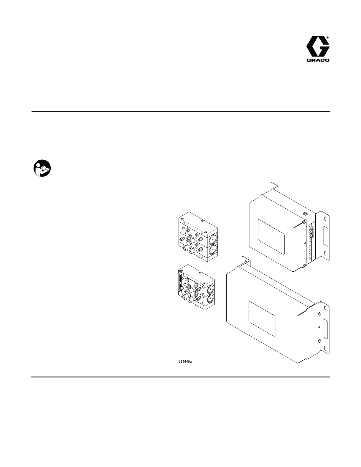
Instructions-Parts
Color Change K
To add optional color change function to ProMix® PD2K Electronic Proportioners. Kits include low or
high pressure color/catalyst change valves and a Non-IS or IS control module.
For professional use only.
Important Safety Instructions
Read all warnings and instructions in this manual and in your PD2K
proportioner manual. Save these instructions.
See page 4
numbers a
informat
for model part
nd approvals
ion.
its
332455F
EN
PROVEN QUALITY. LEADING TECHNOLOGY.
Page 2

Contents
Related Manuals ................................................ 3
Models............................................................... 4
Non-Intrinsically Safe Kits............................. 4
Intrinsically Safe Kits.................................... 6
Warnings ........................................................... 7
Important Isocyanate (ISO) Information................ 10
Isocyanate Conditions.................................. 10
Material Self-ignition..................................... 10
Keep Components A and B Separate............ 10
Moisture Sensitivity of Isocyanates................ 10
Changing Materials ...................................... 11
Setup the Modules.............................................. 12
Setup Non-IS Control Modules...................... 12
Setup IS Control Modules............................. 15
Installa
tion..........................................................17
Mounting
Air Suppl
Groundi
Non-Haz
Hazardo
Install
Install
Connec
the Color Change Control
Module........................................... 17
y.................................................... 17
ng ................................................... 17
ardous Location.............................. 18
us Location ..................................... 20
the Valve Manifolds ............................ 21
the Back Pressure Regulator (High
Pressu
t the Valve Air Lines.......................... 23
re Systems Only)..................23
Connect the Fluid Lines................................ 24
Install an Expansion Kit ................................ 28
Troubleshooting.................................................. 30
Color Change Solenoid Valves ..................... 30
Color Change Board .................................... 32
Electrical S
Repair................................................................ 41
Parts.................................................................. 44
Dimensi
Weights ............................................................. 69
Technical Data ...................................................73
Graco S
chematics.......................................... 34
Optional Ca
Replace a Color Valve.................................. 41
Replace a Solenoid...................................... 42
Replace the ColorChangeBoard Fuse........... 42
Replace the Color Change Board.................. 43
Non-IS Color Change Kits ............................ 45
IS Color Change Kits.................................... 47
Valve Manifolds ........................................... 49
Color Change Control Module Kits ................ 60
Expansion Kits............................................. 64
ons ........................................................ 66
tandard Warranty.................................... 74
bles and Modules....................... 40
2
332455F
Page 3

Related Manuals
Related Manuals
Manual No. Description
3A2800 PD2K Proporti
Manual, Manua
332457 PD2K Proportioner Installation
Manual, Manual Systems
332562
3A2801
PD2K Propor
Manual, Man
Mix Manifold Instructions-Parts
Manual
oner Repair-Parts
lSystems
tioner Operation
ual Systems
Manual No. Description
332339 Pump Repair-P
332454
332456 3rd and 4th P
Color Change Valve Repair-Parts
Manual
Instructio
ns-Parts Manual
arts Manual
ump Kits
332455F 3
Page 4
Models
Models
Non-Intrinsically Safe Kits
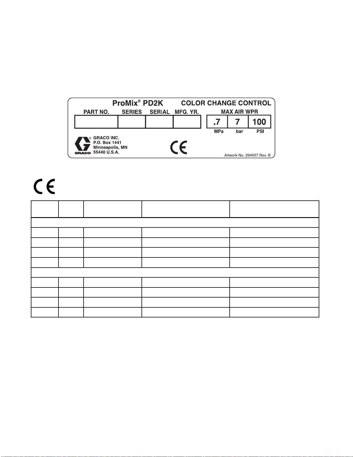
See the modul
information
Figure 1 Non-Intrinsically Safe Color Change Control
Module Label
Kit No.
24R915 A 2 color or 2 catalyst
24R916 A 4 color
e identification label for product part number, maximum air working pressure, and approval
and certification.
Series
Kit Description Maximum Air Working Pressure
(Control Module)
Low Pres
or 4 catalyst
sure Non-Circulating Color Change Kits
100 psi (0.7 MPa, 7.0 bar) 300 psi (2.068 MPa, 20.68 bar)
100 psi (0.7 MPa, 7.0 bar) 300 psi (2.068 MPa, 20.68 bar)
Maximum Fluid Working
Pressure (Valves)
24R917 A 6 color
24R918 A 8 color
24R919 A 2 color
24R920 A 4 color
921
24R
24R922 A 8 color
A6co
lor
100 psi
100 psi (0.7 MPa, 7.0 bar) 300 psi (2.068 MPa, 20.68 bar)
Low Pressure Circulating Color Change Kits
100 p
100 psi (0.7 MPa, 7.0 bar) 300 psi (2.068 MPa, 20.68 bar)
100 psi (0.7 MPa, 7.0 bar) 300 psi (2.068 MPa, 20.68 bar)
10
(0.7 MPa, 7.0 bar)
si (0.7 MPa, 7.0 bar)
0psi(0.7MPa,7.0bar)
300 psi
300 p
30
(2.068 MPa, 20.68 bar)
si (2.068 MPa, 20.68 bar)
0 psi (2.068 MPa, 20.68 bar)
4
332455F
Page 5
Models
Kit No.
24R959 A 2 color or 2 cat
24R960 A 4 color or 4 catalyst
24R961 A 6 color
24R962 A 8 color
24T579 A
24T580 A
24R963 A 2 color
24R96
24R965 A 6 color
24R966 A 8 color
Series
4
Kit Descriptio
High Press
2 catalyst (acid
compatible)
4 catalyst (acid
compatible)
A4colo
r
n
High Pressure Non-Circulating Color Change Kits
alyst
ure Acid Compatible Non-Circulating Catalyst Change Kits
High Pr
Maximum Air Wor
(Control Modul
100 psi (0.7 MPa, 7.0 bar) 1500 psi (10.34 MPa, 103.4 bar)
100 psi (0.7 M
100 psi (0.7 MPa, 7.0 bar) 1500 psi (10.34 MPa, 103.4 bar)
100 psi (0.7 MPa, 7.0 bar) 1500 psi (10.34 MPa, 103.4 bar)
100 psi (0.7 MPa, 7.0 bar) 1500 psi (10.34 MPa, 103.4 bar)
100 psi (0.7 MPa, 7.0 bar) 1500 psi (10.34 MPa, 103.4 bar)
essure Circulating Color Change Kits
100 psi (0.7 MPa, 7.0 bar) 1500 psi (10.34 MPa, 103.4 bar)
100 psi (0.7 MPa, 7.0 bar) 1500 psi (10.34 MPa, 103.4 bar)
100 ps
100 psi (0.7 MPa, 7.0 bar) 1500 psi (10.34 MPa, 103.4 bar)
i(0.7MPa,7.0bar)
king Pressure
e)
Pa, 7.0 bar)
Maximum Fluid W
Pressure (Valv
1500 psi (10.
1500 p
si (10.34 MPa, 103.4 bar)
orking
es)
34 MPa, 103.4 bar)
332455F 5
Page 6
Models
Intrinsicall
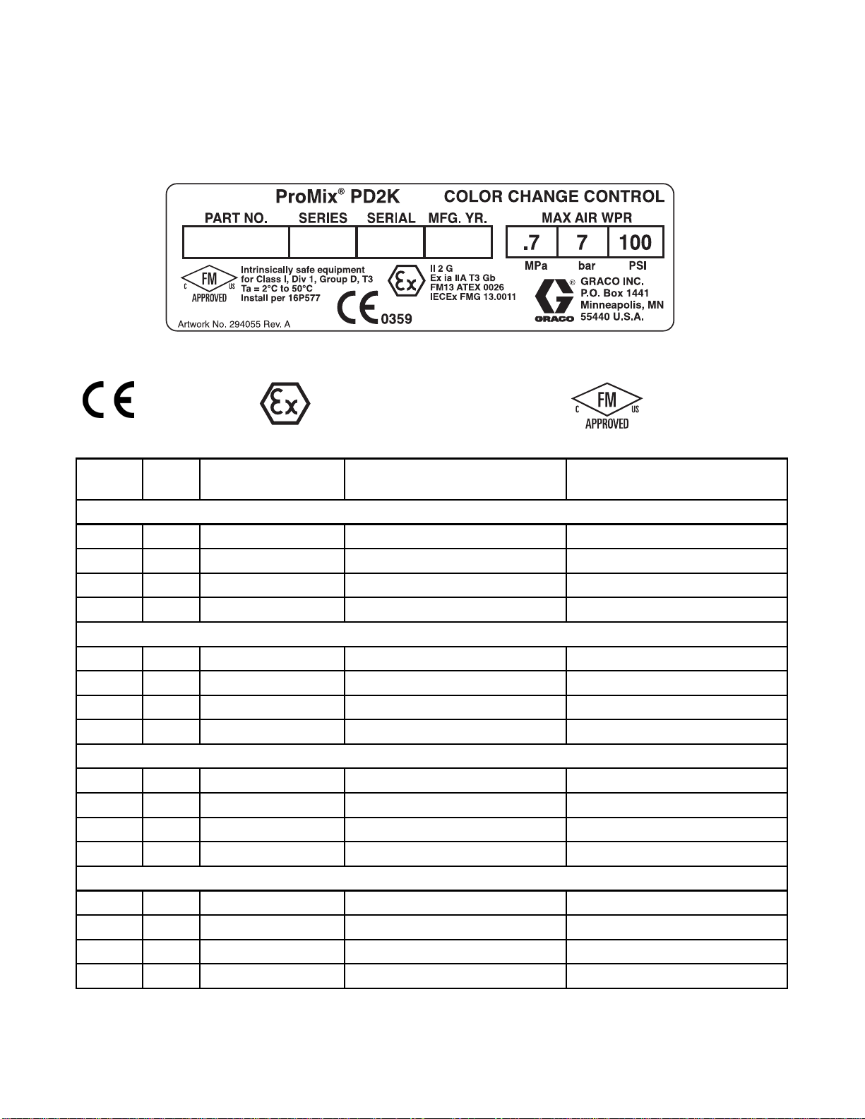
See the module identification label for product part number, maximum air working pressure, and approval
information and certification.
Figure 2 Intrinsically Safe Color Change Control
Module Label
Kit No.
ySafeKits
0359
Series
II 2 G
Kit Description Maximum Air Working Pressure
(Control Module)
Low Pressure Non-Circulating Color Change Kits
Maximum Fluid Working
Pressure (Valves)
24T343 A 2 color or 2 catalyst
24T344 A 4 color or 4 catalyst
24T345 A 6 color
24T346 A 8 color
Low Pressure Circulating Color Change Kits
24T347 A 2 color
24T348 A 4 color
24T349 A 6 color
24T350 A 8 color
High Pressure Non-Circulating Color Change Kits
24T351 A 2 color or 2 catalyst
24T352 A 4 color or 4 catalyst
24T353 A 6 color
24T354 A 8 color
High Pressure Circulating Color Change Kits
24T355 A 2 color
24T356 A 4 color
100 psi (0.7 MPa, 7.0 bar) 300 psi (2.068 MPa, 20.68 bar)
100 psi (0.7 MPa, 7.0 bar) 300 psi (2.068 MPa, 20.68 bar)
100 psi (0.7 MPa, 7.0 bar) 300 psi (2.068 MPa, 20.68 bar)
100 psi (0.7 MPa, 7.0 bar) 300 psi (2.068 MPa, 20.68 bar)
100 psi (0.7 MPa, 7.0 bar) 300 psi (2.068 MPa, 20.68 bar)
100 psi (0.7 MPa, 7.0 bar) 300 psi (2.068 MPa, 20.68 bar)
100 psi (0.7 MPa, 7.0 bar) 300 psi (2.068 MPa, 20.68 bar)
100 psi (0.7 MPa, 7.0 bar) 300 psi (2.068 MPa, 20.68 bar)
100 psi (0.7 MPa, 7.0 bar) 1500 psi (10.34 MPa, 103.4 bar)
100 psi (0.7 MPa, 7.0 bar) 1500 psi (10.34 MPa, 103.4 bar)
100 psi (0.7 MPa, 7.0 bar) 1500 psi (10.34 MPa, 103.4 bar)
100 psi (0.7 MPa, 7.0 bar) 1500 psi (10.34 MPa, 103.4 bar)
100 psi (0.7 MPa, 7.0 bar) 1500 psi (10.34 MPa, 103.4 bar)
100 psi (0.7 MPa, 7.0 bar) 1500 psi (10.34 MPa, 103.4 bar)
24T357 A 6 color
24T358 A 8 color
100 psi (0.7 MPa, 7.0 bar) 1500 psi (10.34 MPa, 103.4 bar)
100 psi (0.7 MPa, 7.0 bar) 1500 psi (10.34 MPa, 103.4 bar)
6 332455F
Page 7
Warnings
Warnings
The following
exclamation p
risks. When th
Warnings. Pr
the body of th
warnings are for the setup, use, grounding, maintenance and repair of this equipment. The
oint symbol alerts you to a general warning and the hazard symbol refers to procedure-specific
ese symbols appear in the body of this manual or on warning labels, refer backtothese
oduct-specific hazard symbols and warnings not covered in this section may appear throughout
is manual where applicable.
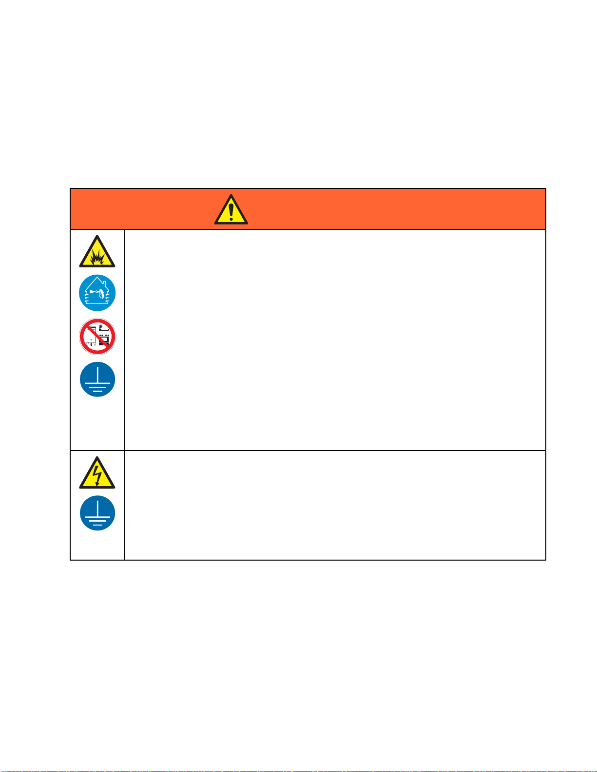
WARNING
FIRE AND EXPLOSION HAZARD
Flammable
prevent fir
• Use equipment only in well ventilated area.
• Eliminat
plastic d
• Keep work area free of debris, including solvent, rags and gasoline.
• Do not plug or unplug power cords, or turn power or light switches on or off when flammable
fumes are present.
•Grounda
• Use only grounded hoses.
• Hold gun firmly to side of grounded pail when triggering into pail. Do not use pail liners unless
they are antistatic or conductive.
• Stop op
equipm
• Keep a working fire extinguisher in the work area.
fumes, such as solvent and paint fumes, in work area can ignite or explode. To help
e and explosion:
e all ignition sources; such as pilot lights, cigarettes, portable electric lamps, and
rop cloths (potential static arc).
ll equipment in the work area. See Grounding instructions.
eration immediately if static sparking occurs or you feel a shock, Do not use
ent until you identify and correct the problem.
332455F
ELECTRIC SHOCK HAZARD
This equipment must be grounded. Improper grounding, setup, or usage of the system can
cause electric shock.
• Turn off and disconnect power at main switch before disconnecting any cables and before
servicing or installing equipment.
• Connect only to grounded power source.
lectrical wiring must be done by a qualified electrician and comply with all local codes
•Alle
egulations.
and r
7
Page 8
Warnings
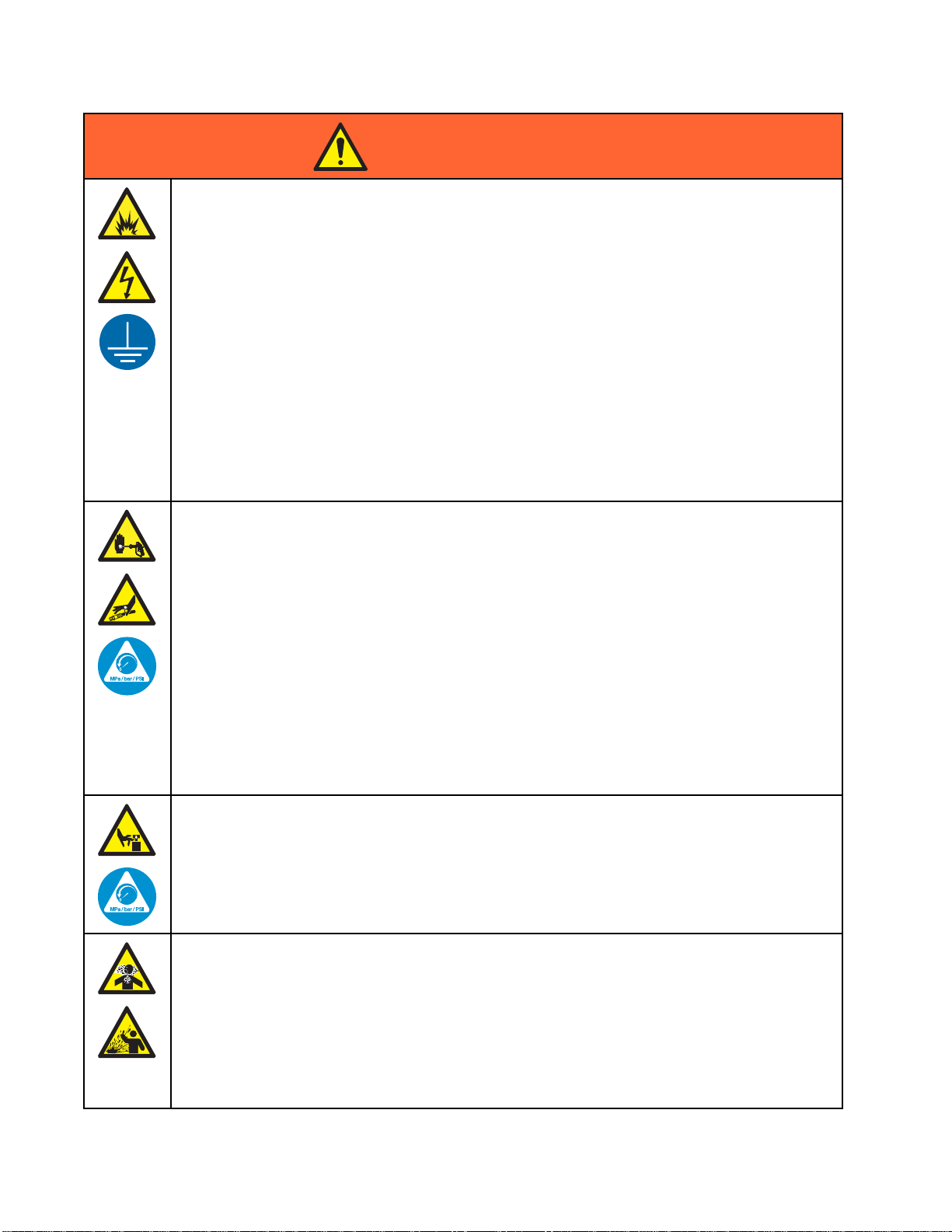
WARNING
INTRINSIC SAFETY
Intrinsically safe equipment that is installed improperly or connected to non-intrinsically safe
equipment will create a hazardous condition and can cause fire, explosion, or electric shock.
Follow local regulations and the following safety requirements.
• Besureyouri
electrical a
and 2 (Europ
NFPA 33, NEC
• To help prevent fire and explosion:
• Do not install equipment approved only for a non-hazardous location in a hazardous
location. See model ID label for the intrinsic safety rating of your model.
• Do not subs
• Equipment that comes in contact with the intrinsically safe terminals must be rated for Intrinsic
Safety. This includes DC voltage meters, ohmmeters, cables, and connections. Remove the
unit from the hazardous area when troubleshooting.
SKIN INJECTION HAZARD
High-pressure fluid from gun, hose leaks, or ruptured components will pierce skin. This may
look like just a cut, but it is a serious injury that can result in amputation. Get immediate surgical
treatment.
•Donotsp
• Engage trigger lock when not spraying.
• Do not point gun at anyone or at any part of the body.
•Donotp
• Do not stop or deflect leaks with your hand, body, glove, or rag.
• Follow the Pressure Relief Procedure when you stop spraying/dispensing and before
cleaning, checking, or servicing equipment.
•Tight
• Check hoses and couplings daily. Replace worn or damaged parts immediately.
en all fluid connections before operating the equipment.
nstallation complies with national, state, and local codes for the installation of
pparatus in a Class I, Group D, Division 1 (North America) or Class I, Zones 1
e) Hazardous Location, including all of the local safety fire codes (for example,
500 and 516, OSHA 1910.107, etc.).
titute system components as this may impair intrinsic safety.
ray without tip guard and trigger guard installed.
ut your hand over the spray tip.
MOVING PARTS HAZARD
Moving parts can pinch, cut or amputate fingers and other body parts.
• Keep clear of moving parts.
• Do not operate equipment with protective guards or covers removed.
ssurized equipment can start without warning. Before checking, moving, or servicing
•Pre
ipment, follow the Pressure Relief Procedure and disconnect all power sources.
equ
ICFLUIDORFUMES
TOX
ic fluids or fumes can cause serious injury or death if splashed in the eyes or on skin,
Tox
aled, or swallowed.
inh
• Read MSDSs to know the specific hazards of the fluids you are using.
ore hazardous fluid in approved containers, and dispose of it according to applicable
•St
idelines.
gu
• Always wear chemically impermeable gloves when spraying, dispensing, or cleaning
equipment.
8 332455F
Page 9

Warnings
WARNING
PERSONAL PROTECTIVE EQUIPMENT
Wear appropriate protective equipment when in the work area to help prevent serious injury,
including eye injury, hearing loss, inhalation of toxic fumes, and burns. This protective
equipment includes but is not limited to:
• Protective eyewear, and hearing protection.
• Respirators, protective clothing, and gloves as recommended by the fluid and solvent
manufacturer.
EQUIPMENT M
Misuse can
• Do not operate the unit when fatigued or under the influence of drugs or alcohol.
• Do not exce
system com
• Use fluids and solvents that are compatible with equipment wetted parts. See Technical Data
in all equipment manuals. Read fluid and solvent manufacturer’s warnings. For complete
information about your material, request MSDS from distributor or retailer.
• Do not leave the work area while equipment is energized or under pressure.
•Turnoffa
• Check equipment daily. Repair or replace worn or damaged parts immediately with genuine
manufacturer’s replacement parts only.
• Do not alter or modify equipment. Alterations or modifications may void agency approvals
and create safety hazards.
•Makesu
• Use equipment only for its intended purpose. Call your distributor for information.
• Route hoses and cables away from traffic areas, sharp edges, moving parts, and hot surfaces.
•Donotk
• Keep children and animals away from work area.
• Comply with all applicable safety regulations.
ISUSE HAZARD
cause death or serious injury.
ed the maximum working pressure or temperature rating of the lowest rated
ponent. See Technical Data in all equipment manuals.
ll equipment and follow the Pressure Relief Procedure when equipment is not in use.
re all equipment is rated and approved for the environment in which you are using it.
ink or over bend hoses or use hoses to pull equipment.
332455F 9
Page 10
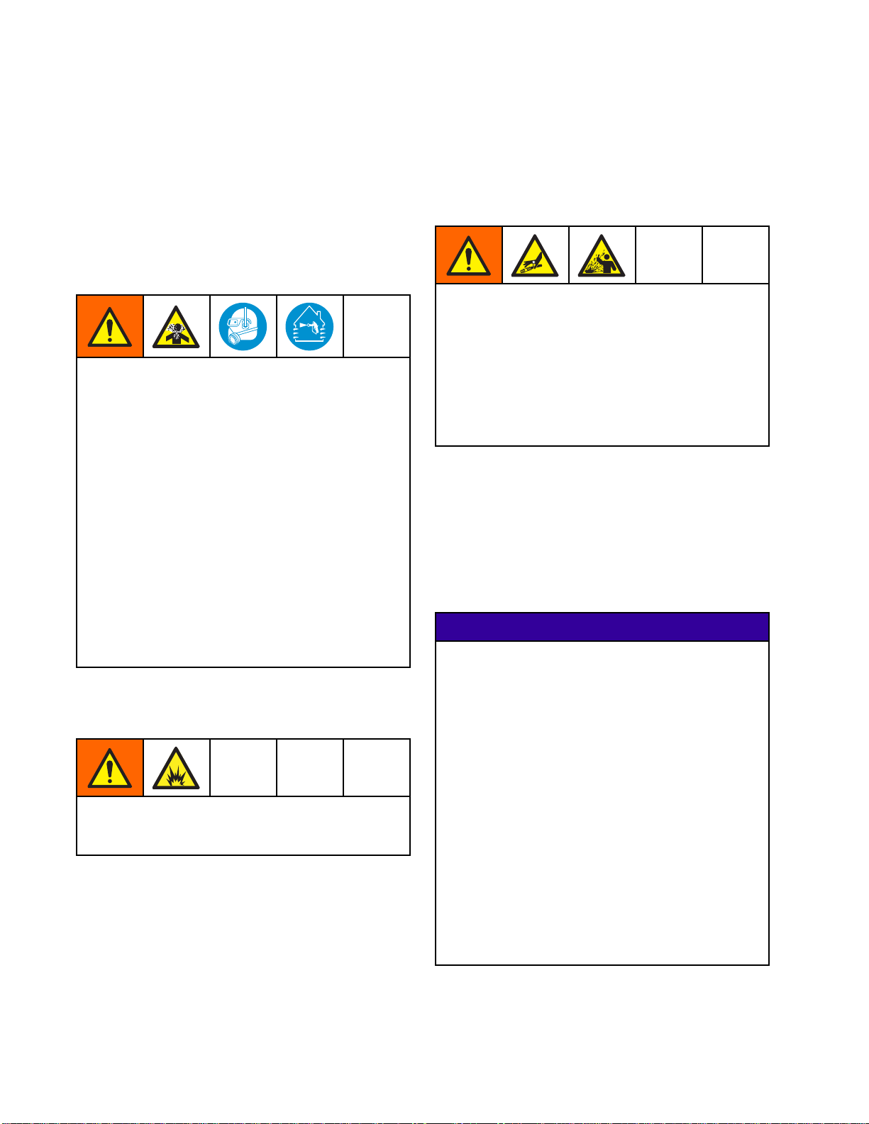
Important Isocy
anate (ISO) Information
Important Iso
Isocyanates (ISO) are catalysts used in two
component materials.
cyanate (ISO) Information
Isocyanate Conditions
Spraying or dispensing materials containing
isocyanates creates potentially harmful mists,
vapors, and atomized particulates.
Read material manufacturer’s warnings and
material MSDS to know specific hazards and
precautions related to isocyanates.
Prevent inhalation of isocyanate mists, vapors,
and atomized particulates by providing sufficient
ventilation in the work area. If sufficient ventilation
is not available, a supplied-air respirator is required
foreveryoneintheworkarea.
To prevent contact with isocyanates, appropriate
personal protective equipment, including
chemically impermeable gloves, boots, aprons,
and goggles, is also required for everyone in the
work area.
Keep Components A and B Separate
Cross-contamination can result in cured
material in fluid lines which could cause serious
injury or damage equipment. To prevent
cross-contamination:
• Never interchange component A and component
Bwettedparts.
• Never use solvent on one side if it has been
contaminated from the other side.
Moisture Sensitivity of Isocyanates
Exposure to moisture (such as humidity) will cause
ISO to partially cure; forming small, hard, abrasive
crystals, which become suspended in the fluid.
Eventually a film will form on the surface and the ISO
will begin to gel, increasing in viscosity.
NOTICE
Partially cured ISO will reduce performance and
the life of all wetted parts.
• Always use a sealed container with a desiccant
Material Self-ignition
Some materials may become self-igniting if applied
too thick. Read material manufacturer’s warnings
and material MSDS.
10 332455F
dryer in the vent, or a nitrogen atmosphere.
Never store ISO in an open container.
• Keep the ISO pump wet cup or reservoir (if
installed) filled with appropriate lubricant. The
lubricant creates a barrier between the ISO and
the atmosphere.
• Use only moisture-proof hoses compatible with
ISO.
• Never use reclaimed solvents, which may
contain moisture. Always keep solvent
containers closed when not in use.
• Always lubricate threaded parts with an
appropriate lubricant when reassembling.
NOTE: The amount of film formation and rate of
crystallization varies depending on the blend of ISO,
the humidity, and the temperature.
Page 11

Important Isocy
anate (ISO) Information
Changing Mate
rials
NOTICE
Changing the material types used in your
equipment requires special attention to avoid
equipment damage and downtime.
• When changi
multiple ti
• Always clea
flushing.
• Check with
chemical c
• When chang
or polyur
componen
have amin
often hav
ng materials, flush the equipment
mes to ensure it is thoroughly clean.
n the fluid inlet strainers after
your material manufacturer for
ompatibility.
ing between epoxies and urethanes
eas, disassemble and clean all fluid
ts and change hoses. Epoxies often
es on the B (hardener) side. Polyureas
eaminesontheA(resin)side.
332455F
11
Page 12
Setup the Module
s
Setup the Modu
Setup Non-IS C
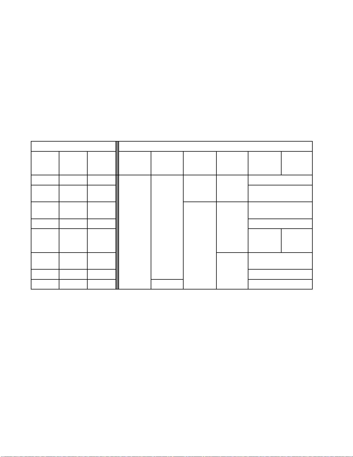
NOTE: The PD2K System can use up to four pumps
and six color change modules in the non-hazardous
area. Use the following table to understand how
many color change modules are needed for the
number of pumps in your system, and which module
should be associated to which pump.
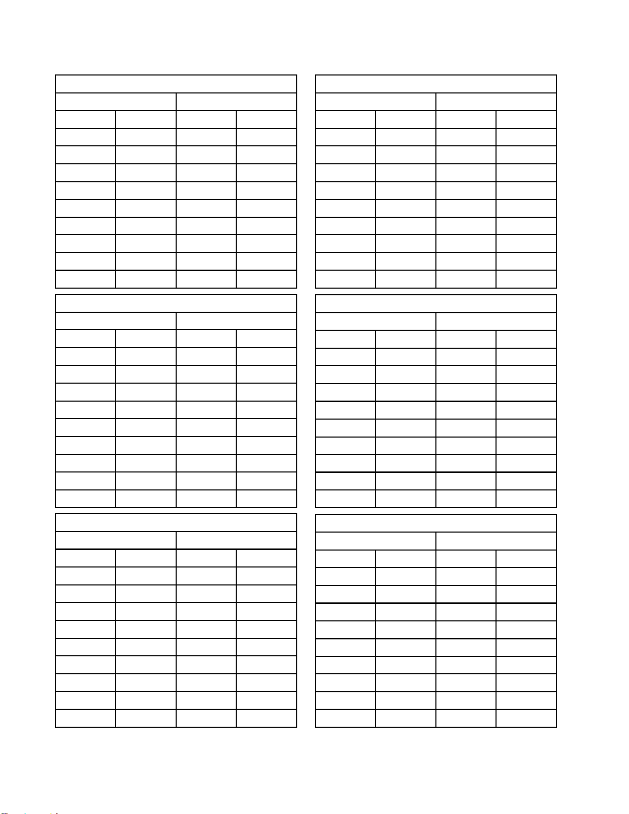
Table 1 . Relationship of Non-IS Color Change Control Modules to Pumps
System Pump Configuration Color Change Control Modules, Colors, and Catalysts
Color
Pump(s)
1 0 1 Not Applicable
112
213
Catalyst
Pump(s)
ontrol Modules
Total
Pumps
les
Module 1
(Colors
1–8)
Module 2
(Colors
9–16)
All Non-IS modules ship from the factory as Module
1 (Colors 1–8). Labels for Modules 2 through 6
areprovidedwiththemodulekit. Affixthelabels
according to your system configuration.
Module
3(Colors
17–24)
Pump # 1 Pump # 1
Module 4
(Colors
25–30)
Catalyst
1–2
Module # 5
Pump # 2
Module
Pump # 2
Catalyst
3–4
#5
2 0 2 Not Applicable
Pump # 1
224
314
303
404
Pump # 1
Pump#3
Pump # 2
Pump # 3
Pump # 4
Module
#5
Pump # 2
Module # 5
Pump # 2
Not Applicable
Not Applicable
Module
#6
Pump # 4
2
1
332455F
Page 13

Setup the Module
s
Configure each module according to its designated
number, as follows:
NOTICE
To avoid damaging the circuit boards, wear Part
No. 112190 grounding strap on your wrist and
ground appropriately.
To avoid elec
system power
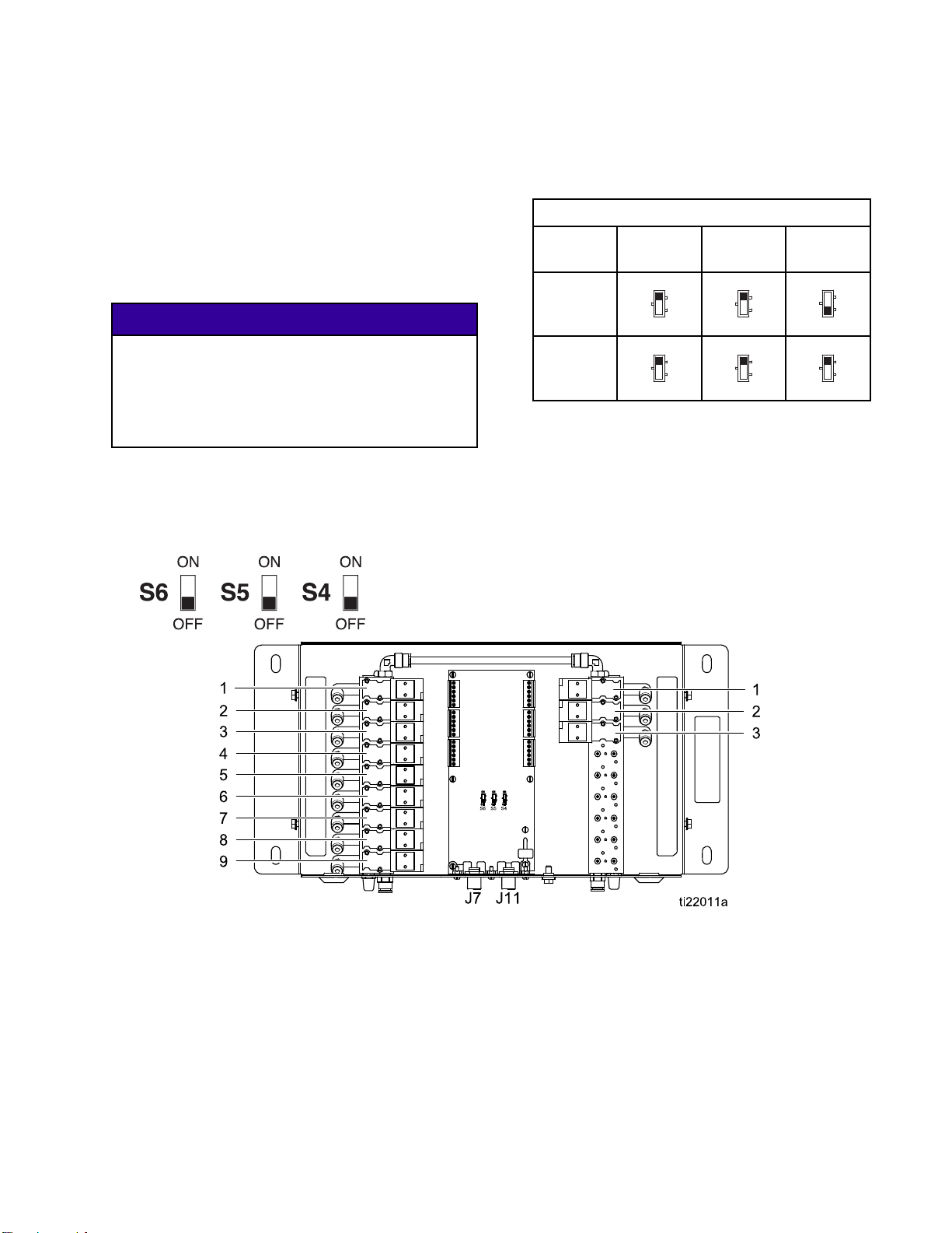
1. Remove elec
2. Open the col
S4, S5, and S
switches a
3. For each module, set the switches to ON or OFF,
as shown in the following table.
trical component damage, remove all
before plugging any connectors.
trical power from the system.
or change module. Locate switches
6 on the control module board. The
re shipped in the OFF position.
Non-IS Control Module Switch Settings
Control
S6 S5 S4
Module
Module 1
Module 2
Module 3
Module 4
Module 5
Module 6
ON
OFF
ON
OFF
ON
OFF
ON
OFF
ON
OFF
ON
OFF
ON
OFF
ON
OFF
ON
OFF
ON
OFF
ON
OFF
ON
OFF
ON
OFF
ON
OFF
ON
OFF
ON
OFF
ON
OFF
ON
OFF
4. Use the following figure and tables to determine
the solenoid valve assigned to each valve in the
valve manifold.
NOTE: There can be only one solvent valve and one
dump valve per pump.
Inlet Manifold Outlet Manifold
Figure 3 Non-IS Control Module
332455F 13
Page 14
Setup the Module
s
Non-IS Control Module 1
Inlet Manifol
Solenoid
1
2
3
4
5
6
7
8
9
Inlet Manifold Outlet Manifold
Solenoid
1
2
3
4
5
6
7
8
d
Valve
Solvent
Color 1
Color 2
Color 3
Color 4
Color 5
Color 6
Color 7
Color 8
Non-IS Control Module 2
Valve
(Solvent)*
Color 9
Color 10
Color 11
Color 12
Color 13
Color 14
Color 15
Outlet Manifo
Solenoid
1Dump
2
3
4
5
6
7
8
9
Solenoid
1
2
3
4
5
6
7
8
ld
Valve
Color 1
Color 2
Color 3
Color 4
Color 5
Color 6
Color 7
Color 8
Valve
(Dump)*
Color 9
Color 10
Color 11
Color 12
Color 13
Color 14
Color 15
Non-IS Control Module 4
Inlet Manifol
Solenoid
1
2
3
4
5
6
7
8 Not Used 8 Not Used
9NotUse
Inlet Manifold Outlet Manifold
Solenoid
1
2
3
4
5
6 Not Used 6 Not Used
7
8 Not Used 8 Not Used
d
Valve
(Solvent)*
Color 25
Color 26
Color 27
Color 28
Color 29
Color 30
d
Non-IS Control Module 5
Valve
(Solvent)*
Catalyst 1
Catalyst 2
Catalyst 3
Catalyst 4
Not Used
Outlet Manifo
Solenoid
1
2
3
4
5
6
7
9NotUse
Solenoid
1
2
3
4
5
7
ld
Valve
(Dump)*
Color 25
Color 26
Color 27
Color 28
Color 29
Color 30
Valve
(Dump)*
Catalyst 1
Catalyst 2
Catalyst 3
Catalyst 4
Not Used
d
9
Inlet Manifold Outlet Manifold
Solenoid
1
2
3
4
5
6
7
8
9
* There should be only one solvent valve and one dump valve per pump.
4
1
Color 16
Non-IS Control Module 3
Valve
(Solvent)*
Color 17
Color 18
Color 19
Color 20
Color 21
Color 22
Color 23
Color 24
9
Solenoid
1
2
3
4
5
6
7
8
9
Color 16
Valve
(Dump)*
Color 17
Color 18
Color 19
Color 20
Color 21
Color 22
Color 23
Color 24
9 Not Used 9 Not Used
Non-IS Control Module 6
Inlet Manifold Outlet Manifold
Solenoid
1
2
3
4 Not Used 4 Not Used
5
6 Not Used 6 Not Used
7
8 Not Used 8 Not Used
9 Not Used 9 Not Used
Valve
(Solvent)*
Catalyst 3
Catalyst 4
Not Used
Not Used
Solenoid
1
2
3
5
7
Valve
(Dump)*
Catalyst 3
Catalyst 4
Not Used
Not Used
332455F
Page 15
Setup the Module
s
Setup IS Contr
ol Modules
NOTE: Two color change control modules may be
installed in the hazardous area. The modules are
labeled 7 or 8. An alternate label is provided with
the module kit for Module 8 (Colors 13–30). Affix the
label according to your system configuration.
Configure eac
number, as f
h module according to its designated
ollows:
NOTICE
To avoid dam
No. 112190
ground app
To avoid electrical component damage, remove all
system power before plugging any connectors.
1. Remove electrical power from the system.
2. Open the color change module. Locate switches
S4, S5, and S6 on the control module board. The
switches may be shipped in the OFF position.
aging the circuit boards, wear Part
grounding strap on your wrist and
ropriately.
3. For each module, set the switches to ON or OFF,
as shown in the following table.
IS Control Mod
Control
ule Switch Settings
S6 S5 S4
Module
Module 7
Module 8
ON
OFF
ON
OFF
ON
OFF
ON
OFF
ON
OFF
ON
OFF
4. Use the following figure and tables to determine
the solenoid valve assigned to each valve in the
valve manifold.
Figure 4 IS Control Module
332455F 15
Page 16

Setup the Module
s
Solenoid
1
2
3
4
5
6
7
8
9
IS Control Module 7
Valve
Color
Solvent
Color 1
Color 2
Color 3
Color 4
Color 5
Color 6
Color 7
Color 8
Solenoid
1
2
3
4
5
6
7
8
9
Valve
Catalyst
Solvent
Catalyst 1
Catalyst 2
Catalyst 3
Catalyst 4
Color 9
Color 10
Color 11
Color 1
2
Inlet Manifol
Solenoid
1
2
3
4
5
6
7
8
9
IS Control Module 8
d
Valve
Color 13
Color 14
Color 15
Color 16
Color 17
Color 18
Color 19
Color 2
Color 21
0
Solenoid
1
2
3
4
5
6
7
8
9
Outlet Manifo
Valve
Color 22
Color 23
Color 24
Color 25
Color 26
Color 27
Color 28
Color 2
Color 30
ld
9
16 332455F
Page 17
Installation
• To avoid electric shock, turn off power at
the main circuit breaker before opening the
enclosure.
Installation
3. Using the equipment as a template, mark the
mounting holes on the wall at a convenient height
for the operator and so the equipment is easily
accessible for maintenance.
4. Drill mounting holes in the wall. Install anchors
as needed.
• All electrical wiring must be done by a qualified
electrician and comply with all local codes and
regulations.
• Do not substitute or modify system components
as this may impair intrinsic safety.
• Do not install equipment approved only for
non-hazardous location in a hazardous location.
See the identification label for the intrinsic safety
rating for your model.
This equipment stays pressurized until pressure
is manually relieved. To help prevent serious
injury from pressurized fluid, such as skin injection,
splashing fluid and moving parts, follow the
Pressure Relief Procedure in the PD2K Operation
Manual before installing the kit.
Mounting the Color Change Control Module
1. See Dimensions, page 66.
2. Ensure that the wall and mounting hardware
are strong enough to support the weight of the
equipment, fluid, hoses, and stress cause during
operation.
5. Bolt the equipment securely.
Air Supply
Connect a clean and dry air supply to the color
change control module air inlet fitting (317); the fitting
is for 1/4 in. (6 mm) OD tubing. Use a 5 micron filter.
Regulate the air pressure to 85–100 psi (0.6–0.7
MPa, 6.0–7.0 bar).
Grounding
This equipment must be grounded to reduce the
risk of static sparking and electric shock. Electric
or static sparking can cause fumes to ignite or
explode. Improper grounding can cause electric
shock. Grounding provides an escape wire for the
electric current.
Connect a ground wire from the color change module
to a true earth ground.
Intrinsically safe color change modules located in the
hazardous area must be connected to a true earth
ground in the hazardous area.
332455F
17
Page 18
Installation
Non-Hazardous Location
NOTE: Non-IS c
control for th
change valves
in the system,
be installed
1. Mount the first non-IS color control module as
described in Mounting the Color Change Control
Module, page 17.
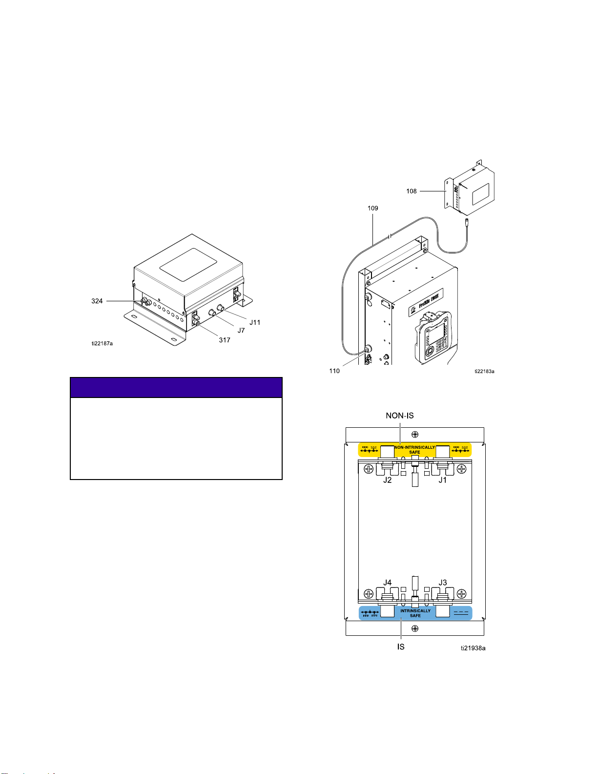
2. Connect the 5–pin CAN cable (109) to J7 on the
color control module (108).
Figure 5 Cable Connector J7 at Non-IS Color
Control Module
olor change control modules provide
e pump’s inlet and outlet color/catalyst
. Depending on the number of valves
as many as six control modules may
in the non-hazardous location.
NOTICE
To avoid damaging the circuit boards, wear
Part No. 112190 grounding strap on your wrist
and ground appropriately.
of the previou
next control m
8. Replace the co
box before tur
Figure 6 Cable Connection at PD2K Electrical
Control Box
s color control module to J7 of the
odule.
ver of the PD2K electrical control
ning on power to the system.
To avoi
remove
conne
3. Remove electrical power from the system.
4. Remove the cover from the PD2K electrical
control box.
5. Install the supplied 2–cable grommet (110) on
the cable (109) and secure the grommet to the
side of the electrical control box.
6. Connect the cable (109) to J2 on the non-IS side
of the isolation board inside the electrical control
box. See Electrical Schematics, page 34 for a list
of M12 CAN cables for use in a non-hazardous
area.
7. To install additional color control modules (six
maximum), mount the module(s) as described
in Mounting the Color Change Control Module,
page 17. Connect a 5–pin CAN cable from J11
d electrical component damage,
all system power before plugging any
ctors.
Figure 7 Detail of Isolation Board Cable Connections
18 332455F
Page 19

Notes
Installation
332455F 19
Page 20

Installation
Hazardous Location
NOTE: IS color
control for co
hazardous loc
modules may be
See IS Color C
alistofmodu
hazardous lo
change control modules provide
lor/catalyst change valves located in the
ation. A maximum of two IS control
installed in the hazardous location.
hange Control Modules, page 62 for
les approved for installation in a
cation.
NOTICE
To avoid dam
No. 112190 g
ground appr
To avoid electrical component damage, remove all
system power before plugging any connectors.
Only approved cables may be used in the
hazardous location. Hazardous location cables are
marked with a light blue flag next to each connector.
See Optional Cables and Modules, page 40 for a
list of M12 CAN cables for use in a hazardous area.
1. Remove electrical power from the system.
2. Mount the first color control module as described
in Mounting the Color Change Control Module,
page 17.
aging the circuit boards, wear Part
rounding strap on your wrist and
opriately.
3. Connect the ha
on the color co
Figure 9 Cable Connectors J7 and J11 at IS
Color Control Module
4. Remove the cover from the PD2K electrical
control box. Install the grommet (G) on the
supplied cable (C1) and secure the grommet
to the side of the electrical control box. Locate
J4ontheISsideoftheisolationboardinthe
electrical control box. Connect the cable (C1) to
J4. See Electrical Schematics, page 34.
zardous location cable (C1) to J7
ntrol module (108).
Figure 10 Detail of Isolation Board Cable
Connections
Figure 8 Intrinsically Safe Cable Connections
20 332455F
Page 21

Installation
5. Mount a second color control module as
described in Mounting the Color Change
Control Module, page 17. Connect the supplied
hazardous location cable (C2) from J11 on the
first color control module to J7 on the second
module.
6. Replace the cover of the PD2K electrical control
box before turning on power to the system.
Install the
NOTE: Always label the color connections to prevent
cross-connections. Label the inlet manifold, outlet
manifold, and each color valve with its assigned color.
The solvent and dump valves should be furthest from
the manifold stack primary inlet or outlet.
1. Install a m
with four
For stabi
(103) to t
Valve Manifolds
ounting bracket (101) on the PD2K
screws (103). High pressure systems:
lity, be sure to fasten the bottom screws
he pump bracket.
2. Install the inlet and outlet valve manifolds (102)
on the mounting bracket (101) with four screws
(104), washers (105), and nuts (106).
NOTE: On low pressure systems, the supplied
bracket (101) will accommodate a manifold
with 16 valve positions (14 colors). On high
pressure systems, the supplied bracket (101) will
accommodate a manifold with 14 valve positions
(12 colors). A larger valve stack will require a
customer supplied/sourced bracket.
3. Repeat for the opposite side of the PD2K.
4. Connect the air lines from the solenoids to the
valves. See Connect the Valve Air Lines, page 23.
NOTE: On high pressure systems, see
Install the Back Pressure Regulator (High
Pressure Systems Only), page 23.
5. Connect the fluid supply lines to the valves. See
Connect the Fluid Lines, page 24.
332455F
Figure 11 Install the Valve Manifolds
21
Page 22

Installation
Notes
2
2
332455F
Page 23
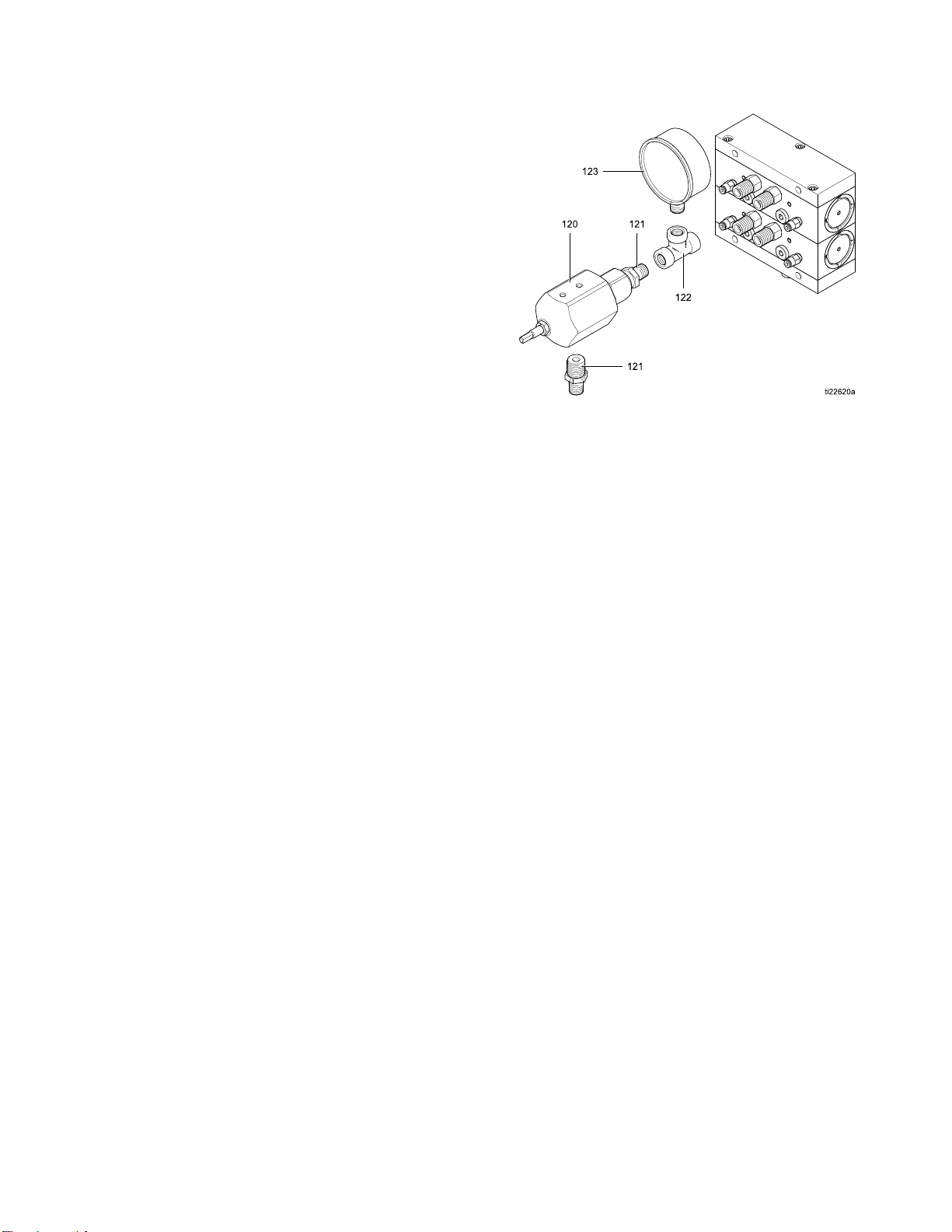
Install the Back Pressure Regulator (High Pressure Systems Only)
NOTE: The back pressure regulator is required on
high pressure systems to prevent the system’s feed
pumps from overdriving the dosing pumps during
color change pump flush and color fill operations.
Adjust the back pressure during the dump process to
be approximately 75% of the supply pressure from
the feed pumps, but never more than 300 psi (2.1
MPa, 21 bar) less than the supply pressure.
Install the back pressure regulator (120) and
attaching hardware at the dump valve of the outlet
manifold stack.
1. Screw the t
the outlet
ee (122) onto the dump valve fitting of
manifold stack.
Installation
Figure 12 Install Back Pressure Regulator at Dump
Valve of Outlet Stack
2. Assemble t
pressure
assembly
3. Install t
tee (122)
4. Connect
facing n
5. Connect
Connect
regulator (120). Screw the regulator
he gauge (123) in the open port of the
.
a 1/4 npt(f) dump line to the downward
ipple (121).
the fluid supply lines to the valves. See
the Fluid Lines, page 24.
he two nipples (121) to the back
Connect the Valve Air Lines
into the tee (122) as shown.
1. Connect 5/32 in. (4 mm) OD air tubes from the
inlet solenoids to the air inlets of each inlet valve,
using the label inside the color control module as
a guide. See Setup the Modules, page 12.
2. Repeat for the outlet valves.
332455F 23
Page 24

Installation
Connect the Fl
uid Lines
Connect Non-Circulating Fluid Lines
NOTE: There can be only one solvent valve (S) and
one dump valve (D) per pump.
NOTE: On high
Install the
Systems Onl
1. Use the top valve of the inlet valve stack as the
solvent valve (S). Connect a solvent supply line
to the 1/4 npt(m) solvent valve inlet on the color
and catalyst valve stacks.
pressure systems, see
Back Pressure Regulator (High Pressure
y), page 23.
INLET COLOR VALVE STACK OUTLET COLOR VALVE STACK
2. Usethetopvalveoftheoutlet valve stack as the
dump valve (D). Connect a waste dump line to
the 1/4 npt(m) dump valve outlet on the color and
catalyst valve stacks.
3. Connect the supply line for each color to the
corresponding color valve fitting (C1, C2, etc.) on
the inlet color valve stack.
4. Connect a supply line from the bottom fitting of
the inlet color valve stack to the inlet manifold of
the material A dosing pump.
5. Connect a supply line from the outlet manifold of
the material A dosing pump to the bottom fitting
of the outlet color valve stack.
Valve Manifold Stack Schematic
4
2
332455F
Page 25

6. Connect a dedicated gun supply line for each
color to the corresponding color valve fitting (C1,
C2, etc.) on the outlet color valve stack. Connect
theotherendofthislinetotheAsideofthemix
manifold at the gun.
7. Connect the supply line for each catalyst to the
corresponding catalyst valve fitting on the inlet
catalyst valve stack.
8. Connect a supply line from the bottom fitting of
the inlet catalyst valve stack to the inlet manifold
of the material B dosing pump.
Installation
9. Connect a supply line from the outlet manifold of
the material B dosing pump to the bottom fitting
of the outlet catalyst valve stack.
10. Connect a dedicated gun supply line for each
catalyst to the corresponding catalyst valve fitting
on the outlet catalyst valve stack. Connect the
other end of this line to the B side of the mix
manifold at the gun.
NOTE: If your system uses more colors than
catalysts, branch the catalyst line to connect it to
each mix manifold. Install a check valve on each
branch of the catalyst line.
NOTE: For ease of maintenance, install a ball
valve at all fluid line tees.
11. The mix manifold is belt-mounted. Connect a
fluid hose between the manifold outlet and the
gun inlet.
Figure 13 Color Change Connections
(Non-Circulating System)
KEY
A Air inlet
W
S Solvent fitting
C1 Color 1 fi
C2 Color 2 fitting
Seal weep and
lubrication port
tting
332455F 25
Page 26

Installation
Connect Circulating Fluid Lines
Circulation valves enable constant circulation of a
color when that color is not being sprayed:
•Whenacolorva
the dosing pum
inlet color v
a circulatio
manifold, th
• When a color v
shut off. Th
A dosing pum
sprayed, as
NOTE: There can be only one solvent valve (S) and
one dump valve (D) per pump.
NOTE: On high pressure systems, see
Install the Back Pressure Regulator (High Pressure
Systems Only), page 23.
1. Connect a
Connect N
These lin
spraying
2. Connect
a. Connect a 1/4 npt(f) circulation line for each
color from the color valve’s circulation fitting
(R1, R2, etc.) on the inlet color valve stack
(B) to the corresponding circulation fitting
(R1, R2, etc.) on the outlet color valve
stack (C). This circulation line bypasses the
material A dosing pump when the color valve
is closed, allowing continuous circulation of
that color.
b. Install a Y fitting (D) in the A side of the mix
manifold (F). Install a fluid shutoff valve (E)
in one branch of the Y fitting. Connect a fluid
lve is closed, the system bypasses
p by directing that color from the
alve to the outlet color valve through
n line, then to a Y fitting at the mix
en back to the color supply.
alve is open, the circulation line is
e color is directed through the material
p and out to the gun to be mixed and
in normal operation.
ll fluid lines as described in
on-Circulating Fluid Lines, page 24.
es are used during normal mixing and
.
the circulation lines as follows:
return line (H) to the shutoff valve, to circulate
the color back to the color supply (A).
NOTE: The fluid shutoff valve (E) must be
closed when spraying, to allow proper ratio
mixing and flow from the gun (G).
c. Connect a dedicated gun supply line for
each color to the corresponding color valve
(C1, C2, etc.) on the outlet color valve stack.
Connect the other end of this line to the open
branch of the Y fitting (D).
Figure 14 Valve Manifold Connections (Circulating
System)
KEY
SSolven
C1 Color 1 fitting
C2 Color 2 fitting
R1
R2
Colo
Color 2 circulation fitting
tfitting
r 1 circulation fitting
26 332455F
Page 27

Fluid Flow Schematic Diagram in Circulating Mode (Pump Not Shown for Clarity)
Installation
KEY
A
B Inlet color stack
C Outlet color stack
D
Color supply
Y fitting at mix manifold
Aport
KEY
E
F
G Spray gun
H
Fluid shutoff valve
Mix manifold
Returnlinetofluid
supply
332455F
27
Page 28

Installation
Install an Expansion Kit
Expansion Kits are available to add
valves or manifolds to your system. See
Expansion Kits, page 64 for available kits.
1. Remove elect
2. Relieve pres
Operation M
3. Open the con
solenoid(s
position(
Setup the M
of the tubi
4. Connect th
pins on th
Electric
NOTE: If i
necessar
shownint
step 6.
5. If your k
the scre
the rods
t order. Install the new manifold block (1).
correc
The new
in correct location of the solvent and dump
mainta
. Screw the rods (16) included in the kit
valves
e existing rods. Slide the existing manifold
into th
s onto the rods, being sure that they are in
block
me positions as before. Ensure all o-rings
the sa
) are in place, then install the screws (10).
(6, 17
rical power from the system.
sure as described in your PD2K
anual.
trol module cover. Install the
) and air fitting(s) at the appropriate
s) in the solenoid manifold. See
odules, page 12. Connect one end
ng to the solenoid’s air fitting.
e solenoid wires to the appropriate
e control module board. See
al Schematics, page 34.
nstalling a one valve kit, it is not
y to disassemble the manifold stack as
he figure. Skip step 5 and go on to
it is adding a manifold block (1), remove
ws (10). Slide the existing manifolds off
(15, 16), keeping the manifolds in the
block must be in the bottom position to
6. Install the valves as follows:
a. For a one valve kit, remove the plug
(4) and o-ring (2). Install a new o-ring
(2), the valve (3), and retainer (5),
using the valve installation tool. See
Replace a Color Valve, page 41.
b. For a manifold kit with one valve, install
the o-ring (2), valve (3), and retainer (5),
using the valve installation tool. See
Replace a Color Valve, page 41.Installthe
plug (4) in the unused manifold port.
c. For a manifold kit with two valves, install
the o-rings (2), valves (3), and retainers
(5), using the valve installation tool. See
Replace a Color Valve, page 41.
7. Install the o-ring(s) (12) and fluid fitting(s) (13).
Connect fluid lines to the fittings.
8. Install the air fitting(s) (14). Connect the tubing
from the solenoid valve(s) (see step 3) to the
fitting(s).
9. Install the control module cover.
10. Return the unit to service.
28 332455F
Page 29

Installation
Install an Exp
ansion Kit (Low Pressure
Valve Manifold Shown)
Non-Circul
ating
Circulating
332455F 29
Page 30

Troubleshootin
g
Troubleshooting
NOTE: Check all possible remedies before disassembling the system.
Color Chang
NOTE: Refer to Electrical Schematics, page 34. If the color change valves are not turning on or off correctly, it
could be caused by one of the following.
Cause Solution
1. Air regulator pressure
set too high or too low.
2. Airore
damaged o
are loos
3. Solenoid failure. Check the applicable solenoid’s LED; see Color Change Board, page 32. If lit,
e.
e Solenoid Valves
Check that air pressure is at least 85 psi (0.6 MPa, 6.0 bar). Do not go above 100
psi (0.7 MPa, 7.0 bar).
lectrical lines
r connections
Visually inspect air and electrical lines for kinks, damage, or loose connections.
Service or replace as needed.
proceed with the following checks. If not lit, go to Cause 4.
Remove
the pin
• In a non-hazardous location, replace the solenoid if voltage is 24 Vdc.
• In a hazardous location, replace the solenoid if voltage is between 9–15 Vdc.
Test the valves as explained under Maintenance Screen 4 in your PD2K
Operation manual. Valves should open and close quickly. If the valves actuate
slowly, it could be caused by:
•Airp
the connector for the applicable solenoid and measure voltage across
s on the board:
ressuretothevalveactuatorsistoolow. SeeCause1.
•Sole
•Some
noid is clogged. Make sure the air supply has a 5 micron filter installed.
thing is restricting the solenoid or tubing. Check for air output from the
ine for the corresponding solenoid when the valve is actuated. Clear the
air l
triction.
res
30 332455F
Page 31

Cause Solution
Troubleshootin
g
4. Control boa
failure.
rd or cable
Ifthereisnov
LEDs D8, D9, an
in the module a
If D9 is not lit:
• Verify the condition of the fuse (F1) and replace if necessary. See
Replace the Color Change Board Fuse, page 42.
• Check if the cable is disconnected or damaged.
• Check the isolation board. See the PD2K Repair-Parts manual.
If D8 is not b
• Cycle the system power.
• Check if the cable is disconnected or damaged.
• Check the isolation board. See the PD2K Repair-Parts manual.
If D10 is not occasionally blinking:
• Check if t
• Check the
oltage across the pins on the board or it is less than 9 Vdc, check
d D10. If they are lit and functioning properly, or other solenoids
re working properly, replace the color change board.
linking:
he cable is disconnected or damaged.
isolation board. See the PD2K Repair-Parts manual.
332455F 31
Page 32

Troubleshootin
g
Color Change B
oard
NOTICE
To avoid damaging the circuit boards, wear Part
No. 112190 grounding strap on your wrist and
ground appropriately.
To avoid electrical component damage, remove all
system power before plugging any connectors.
Figure 15 Color Change Board
32 332455F
Page 33

Color Change Board Diagnostics
Troubleshootin
g
Component or
Indicator
D8
D9
D10
D27–D39,
D41, D43–D46
F1 Fuse, 0.12
Description Diagnosis
LED (green) Blinks (heartbeat) during normal operation.
LED (green)
LED (yellow)
LED (green)
5A,125V
Turns on when
board.
Turns on when board is communicating with
electronic control.
Turn on when a signal is sent to actuate the
related solenoid valve.
power is supplied to the
332455F 33
Page 34

Electrical Sche
matics
Electrical Sc
hematics
NOTE: The electrical schematic illustrates all possible
wiring expansions in a ProMix PD2K system. Some
components shown are not included with all systems.
NOTE: See Optional Cables and Modules, page 40,
for a list of cable options.
RELAY
(16U820)
16W159
BREAKOUT MODULE PUMP 2
BREAKOUT MODULE PUMP 4
POWER MODULE
(24R257)
16W159
16W159
(24N527)
(24N527)
SPLITTER
(16P243)
4
CABLE (16T659)
CABLE (16T659)
CABLE (16T659)
CABLE (16T659)
(24P658)
ENCODER AND MOTOR
(16P036, 16P037)
WIRE HARNESS
(24P684, 24P685)
PUMP INLET
TRANSDUCER
(16P289, 16P290)
PUMP OUTLET
TRANSDUCER
(16P289, 16P290)
PUMP V/P FOR
FLUID REG.
UP
DOWN
(16P812)
SOLENOID
MAC SERIES 46
FLOW SENSOR
(120278)
OR G3000 METER
(239716, 258718
16M510, 16M519)
(24P658)
ENCODER AND MOTOR
(16P036, 16P037)
WIRE HARNESS
(24P684, 24P685)
PUMP INLET
TRANSDUCER
(16P289, 16P290)
PUMP OUTLET
TRANSDUCER
(16P289, 16P290)
PUMP V/P FOR
FLUID REG.
UP
DOWN
(16P812)
SOLENOID
MAC SERIES 46
FLOW SENSOR
(120278)
OR G3000 METER
(239716, 258718
16M510, 16M519)
POWER IN
FAN
FAN
2 POSITION
SWITCH
(16U725)
CABLE
16T658
LINE FILTER
(16V446)
CABLE
16H078
TERMINAL BLOCK
(114095)
BREAKOUT MODULE PUMP 1
BREAKOUT MODULE PUMP 3
24V
POWER
SUPPLY
(16T660)
(24N527)
(24N527)
48V-10A POWER SUPPLY
TERMINAL BLOCKS WITH FUSES
16W159
FAN
(24P658)
ENCODER AND MOTOR
(16P036, 16P037)
WIRE HARNESS
(24P684, 24P685)
PUMP INLET
TRANSDUCER
(16P289, 16P290)
PUMP OUTLET
TRANSDUCER
(16P289, 16P290)
PUMP V/P FOR
FLUID REG.
UP
DOWN
(16P812)
SOLENOID
MAC SERIES 46
FLOW SENSOR
(120278)
OR G3000 METER
(239716, 258718
16M510, 16M519)
FAN
(24P658)
ENCODER AND MOTOR
(16P036, 16P037)
WIRE HARNESS
(24P684, 24P685)
PUMP INLET
TRANSDUCER
(16P289, 16P290)
PUMP OUTLET
TRANSDUCER
(16P289, 16P290)
PUMP V/P FOR
FLUID REG.
UP
DOWN
(16P812)
SOLENOID
MAC SERIES 46
FLOW SENSOR
(120278)
OR G3000 METER
(239716, 258718
16M510, 16M519)
Figure 16 Electrical Schematic, Sheet 1
COMMUNICATION
MODULE
(24R910)
3
COMMUNICATION
CABLE (15V206)
MODULE
(24R910)
2
CABLE
3
16T072
CAN
IS BOARD
(24M485)
CABLE
(16T280)
BARRIER
BOARD
(248192)
065161, 065159
5
CABLE
(121227)
5
(121227)
CABLE
3
(121227)
6
(24N935)
MODULE 1
COLOR CHANGE
CABLE
2
(15V206)
GCA
MODULE
EFCM
(24N913)
FLOW RATE ANALOG IN
FLOW RATE ANALOG IN
1
CABLE (16V429)
2
CABLE
(15V206)
6
(24N935)
MODULE 2
COLOR CHANGE
FLOW RATE ANALOG IN
FLOW RATE ANALOG IN
2
CABLE
(15V206)
6
6
6
(24N935)
(24N935)
MODULE 3
COLOR CHANGE
COLOR CHANGE
CABLE
2
(15V206)
GUN TRIGGER INPUTS
119159
119159
119159
119159
SOLENOID (121324)
PRESSURE SWITCH
(121323)
SOLVENT FLOW SWITCH (120278)
SOLVENT METER (258718)
3
ADVANCED
CABLE
DISPLAY MODULE
(121003)
(24E451)
CABLE
1
(24N935)
MODULE 4
MODULE 5
CATALYST CHANGE
CABLE
2
(15V206)
COLOR CHANGE MODULE 7
(24R219)
COLOR CHANGE MODULE 8
(24R219)
(16V426)
BOOTH CONTROL (24M731)
HAZARDOUS LOCATION
NON-HAZARDOUS LOCATION
6
(24N935)
MODULE 6
CATALYST CHANGE
GFB
INTERFACES
LIGHT
TOWER
(15X472)
CABLE
1
(16V426)
7
7
34 332455F
Page 35

Electrical Sche
matics
POWER
SUPPLY
(16T660)
L (BROWN)
N03 N03
2 POSITION
SWITCH
(16U725)
N04 N04
CABLE
(16T658)
L N
LINE
FILTER
(16V446)
L GRND N
CABLE
(16H078)
L N GRND
TERMINAL
BLOCK
(114095)
L N GRND
24V
GRND (GRN/YEL)
N (BLUE)
CABLE (16V429)
1
SPLITTER
(16P243)
2
345
1
UNUSED
UNUSED
UNUSED
13 A1(+) A2(-)
RELAY
14
N L GRND
48V-10A
POWER SUPPLY
(16U820)
+ -
+ - + - + - + -
F4
F3
F2
F1
+ - + - + - + -
DETAIL A, LOW PRESSURE
PUMPS (24M706, 24M714)
BREAKOUT MODULE
(24N527)
2
1 2 3 4 5 1 2 3 4
WIRE HARNESS
(24P684)
CONTINUED ON PAGE 3
2
CABLE
(15V206)
1 2 3 4 5
CAN IS BOARD
2
(NON IS)
(IS)
4
(24M485)
1 2 3 4 5
1
UNUSED
2
3
RED WIRE (065161)
BLACK WIRE (065159)
1 2 3 4 5 1 2 3 4
(24R257)
POWER MODULE
3
DRAIN/FOIL
CABLE (121227)
3
16T072
1 2 3 4 5
CABLE
1
1
2
2
3
3
4
4
5
5
(121227)
1
UNUSED
5
COMM MODULE (24R910)
GFB
INTERFACE
SOLVENT CUTOFF
PWR (RED)
SIG (WHITE)
COM (BLACK)
SHIELD/GRN
SOLVENT
METER
(258718)
GROUND BAR
1 2 3 4 5
CABLE
(16T280)
1 2 3
BARRIER
BOARD
(248192)
3
UNUSED
BREAKOUT MODULE PUMP 1 (24N527)
2
ENCODER/MOTOR
AND
WIRE HARNESS
PUMP 1
SEE DETAIL A OR B
3
1 2 3 4 5 1 2 3 4 5 1 2
TWISTED PAIR CABLE (16W159)
5
4
PUMP 1
PUMP 1
(16P289 OR 16P290)
INLET TRANSDUCER
OUTLET TRANSDUCER
DETAIL B, HIGH PRESSURE
PUMPS (24M707, 24M715)
BREAKOUT MODULE
2
1 2 3 4 5 1 2 3 4
1
2
3
4
5
3
5
6
1 2 3 4
PUMP 1
(16P289 OR 16P290)
V/P FOR FLUID REG.
(24N527)
WIRE HARNESS
(24P685)
UNUSED
5
UNUSED
4
3
10
2
UNUSED
1
CABLE
1
2
3
4
5
3
(121227)
1
2
3
8
4
5
COMM MODULE (24R910)
+12VDC
COM
UNUSED
UNUSED
+12VDC
COM
+12VDC
COM
UNUSED
1
2
3
4
5
6
5
7
8
9
10
11
12
25 PIN D-SUB CABLE
1
7
3 4
5 6 7 8
COM
COM
+24VDC
+24VDC
PWR (RED)
SIG (WHITE)
COM (BLACK)
SHIELD/GRN
UP
DOWN
PUMP 1
PUMP 1
MANIFOLD
G3000
METER
PUMP 1
(EITHER, 239716,
258718,16M510,
OR 16M519)
(16P812 QTY 2)
MAC SERIES 46
SCREW
GRND
3
DRAIN/FOIL
(16T659)
1 2 3 4
+48V
COM
CONTINUED ON PAGE 3
GCA MODULE
EFCM
(24N913)
12
4
252423222120191817161413121110 15987654321
BREAKOUT MODULE PUMP 2 (24N527)
2
1 2 3 4 5 1 2 3 4
+48V
COM
ENCODER/MOTOR
AND
WIRE HARNESS
PUMP 2
SEE DETAIL A OR B
(24P658)
FAN PUMP 1
252423222120191817161413121110 15987654321 252423222120191817161413121110 15987654321
3
1 2 3 4 5 1 2 3 4 5 1 2
4
PUMP 2
(16P289 OR 16P290)
INLET TRANSDUCER
5
PUMP 2
OUTLET TRANSDUCER
TWISTED PAIR CABLE (16W159)
6
1 2 3 4
PUMP 2
(16P289 OR 16P290)
V/P FOR FLUID REG.
25 PIN
(16T659)
D-SUB CABLE
4
1
3 4
COM
COM
+24VDC
+24VDC
UP
DOWN
PUMP 2
PUMP 2
MANIFOLD
(16P812 QTY 2)
MAC SERIES 46
7
5 6 7 8
G3000
METER
PUMP 2
(EITHER, 239716,
258718,16M510,
OR 16M519)
PWR (RED)
SIG (WHITE)
COM (BLACK)
SHIELD/GRN
GRND
SCREW
1 2 3 4
+48V
88
COM
+48V
FAN PUMP 2
252423222120191817161413121110 15987654321
COM
(24P658)
DRAIN/FOIL
UNUSED UNUSED
UNUSED
UNUSED
UNUSED
UNUSED
UNUSED
UNUSED
UNUSED
UNUSED UNUSED
UNUSED
UNUSED UNUSED
POWER IN
UNUSED
UNUSED
DRAIN/FOIL
1 2 3 4 5 6 7 8 9
PUMP ENCODER AND MOTOR
MOTOR
MOUNTING
SCREW
UNUSED
UNUSED UNUSED
UNUSED
12
11
10
(16P037)
UNUSED
UNUSED
1 2 3 4 5 6 7 8 9
UNUSED
UNUSED UNUSED UNUSED
UNUSED
12
11
1 2
MOTOR
MOUNTING
SCREW
1 2 3 4 5 6 7 8 9
PUMP ENCODER AND MOTOR
10
10
(16P036)
1 2 3 4 5 6 7 8 9
UNUSED
10
Figure 17 Electrical Schematic, Sheet 2, Part 1
TINUED ON THE NEXT PAGE
CON
332455F 35
Page 36

Electrical Sche
matics
GUN TRIGGER INPUTS
SIG
1
COM
2
SIG
3
COM
4
SIG
5
COM
6
6
7
SIG
8
COM
9
SIG
10
COM
11
SIG
12
1
2
3
4
5
6
7
7
8
9
10
11
12
1
2
3
9
4
5
COM
FLOW RATE ANALOG IN 1
FLOW RATE ANALOG COMMON 1
FLOW RATE ANALOG IN 2
FLOW RATE ANALOG COMMON 2
FLOW RATE ANALOG IN 3
FLOW RATE ANALOG COMMON 3
FLOW RATE ANALOG IN 4
FLOW RATE ANALOG COMMON 4
UNUSED
UNUSED
UNUSED
UNUSED
CABLE
(121003)
3
GCA MODULE
EFCM
(24N913)
34
252423222120191817161413121110 15987654321 252423222120191817161413121110 15987654321
119159
GFB PRESSURE SWITCH (121323)
SOLVENT FLOW SWITCH (120278)
1
ADVANCED
2
DISPLAY MODULE
3
4
(24E451)
5
1
2
3
4
5
LIGHT
TOWER
(15X472)
25 PIN
(16T659)
D-SUB CABLE
4
1
BREAKOUT MODULE PUMP 3 (24N527)
3
2
1 2 3 4 5 1 2 3 4 1 2 3 4 5 1 2 3 4
ENCODER/MOTOR
WIRE HARNESS
PUMP 3
SEE DETAIL A OR B
1 2 3 4 5 1 2 3 4 5 1 2
AND
4
PUMP 3
(16P289 OR 16P290)
INLET TRANSDUCER
5
PUMP 3
(16P289 OR 16P290)
OUTLET TRANSDUCER
1 2 3 4
TWISTED PAIR CABLE (16W159)
e18 ElectricalSchematic,Sheet2,Part2
Figur
CONTINUED ON THE NEXT PAGE
252423222120191817161413121110 15987654321
6
PUMP 3
V/P FOR FLUID REG.
3 4
COM
+24VDC
+24VDC
UP
PUMP 3
PUMP 3
MANIFOLD
(16P812 QTY 2)
MAC SERIES 46
COM
DOWN
7
5 6 7 8
G3000
METER
PUMP 3
(EITHER, 239716,
258718,16M510,
OR 16M519)
PWR (RED)
SIG (WHITE)
COM (BLACK)
SCREW
25 PIN D-SUB CABLE
8
1 2 3 4
+48V
+48V
COM
SHIELD/GRN
FAN PUMP 3
GRND
COM
(24P658)
(16T659)
2
SEE DETAIL A OR B
4
ENCODER/MOTOR
AND
WIRE HARNESS
PUMP 4
5
PUMP 4
(16P289 OR 16P290)
OUTLET TRANSDUCER
252423222120191817161413121110 15987654321
6
1 2 3 4
PUMP 4
V/P FOR FLUID REG.
3 4
COM
+24VDC
+24VDC
UP
PUMP 4
PUMP 4
MANIFOLD
(16P812 QTY 2)
MAC SERIES 46
7
COM
DOWN
1
BREAKOUT MODULE PUMP 4 (24N527)
3
4
1 2 3 4 5 1 2 3 4 5 1 2 1 2 3 4
PUMP 4
(16P289 OR 16P290)
INLET TRANSDUCER
TWISTED PAIR CABLE (16W159)
5 6 7 8
PWR (RED)
SIG (WHITE)
G3000
METER
PUMP 4
(EITHER, 239716,
258718,16M510,
OR 16M519)
+48V
COM (BLACK)
SHIELD/GRN
GRND
SCREW
COM
8
+48V
COM
(24P658)
FAN PUMP 4
36 332455F
Page 37

Electrical Sche
matics
FLUSH
COLOR 1
COLOR 2
COLOR 3
COLOR 4
COLOR 5
COLOR 6
COLOR 7
COLOR 8
*FLUSH
COLOR 9
COLOR 10
COLOR 11
COLOR 12
COLOR 13
COLOR 14
COLOR 15
COLOR 16
CABLE (15V206)
2
MANIFOLD
MANIFOLD
+12VDC
COM
+12VDC
COM
+12VDC
COM
+12VDC
COM
+12VDC
COM
+12VDC
COM
+12VDC
COM
+12VDC
COM
+12VDC
COM
+12VDC
COM
+12VDC
COM
+12VDC
COM
+12VDC
COM
+12VDC
COM
+12VDC
COM
+12VDC
COM
+12VDC
COM
+12VDC
COM
1
2
3
4
5
6
1
2
3
4
5
6
1
2
3
4
5
6
2
1
2
3
4
5
6
1
2
3
4
5
6
1
2
3
4
5
6
FROM CAN IS BOARD (24M485) ON PAGE 2
2
345
1
COLOR
CHANGE
MODULE 1
(COLORS
1
+12VDC
2
COM
3
+12VDC
J9
4
COM
5
+12VDC
6
COM
1
+12VDC
2
COM
3
+12VDC
4
COM
5
+12VDC
6
COM
1
+12VDC
2
COM
3
+12VDC
4
COM
5
+12VDC
6
COM
J8
J15
J14
1 THRU 8)
6
2
345
1
J16
J10
CABLE
J8
J15
J14
2
345
1
COLOR
CHANGE
MODULE 2
(COLORS
9 THRU 16)
6
2
345
1
J16
J10
J9
(15V206)
1
2
3
4
5
6
1
2
3
4
5
6
1
2
3
4
5
6
+12VDC
COM
+12VDC
COM
+12VDC
COM
+12VDC
COM
+12VDC
COM
+12VDC
COM
+12VDC
COM
+12VDC
COM
+12VDC
COM
MANIFOLD
MANIFOLD
DUMP
COLOR 1
COLOR 2
COLOR 3
COLOR 4
COLOR 5
COLOR 6
COLOR 7
COLOR 8
DUMP*
COLOR 9
COLOR 10
COLOR 11
COLOR 12
COLOR 13
COLOR 14
COLOR 15
COLOR 16
FLUSH
CATALYST 1
CATALYST 2
CATALYST 3
CATALYST 4
FROM CAN IS BOARD (24M485) ON PAGE 2
MANIFOLD
+12VDC
COM
+12VDC
COM
+12VDC
COM
+12VDC
COM
+12VDC
COM
UNUSED
UNUSED
UNUSED
UNUSED
UNUSED
UNUSED
UNUSED
UNUSED
1
2
3
4
5
6
1
2
3
4
5
6
1
2
3
4
5
6
CATALYST
CHANGE
MODULE 5
(CATALYST
1 THRU 4)
J8
J15
J14
2
1
6
345
J16
J10
+12VDC
COM
+12VDC
COM
+12VDC
COM
+12VDC
COM
+12VDC
COM
UNUSED
UNUSED
UNUSED
UNUSED
UNUSED
UNUSED
UNUSED
UNUSED
MANIFOLD
DUMP
CATALYST 1
CATALYST 2
CATALYST 3
CATALYST 4
1
2
3
J9
4
5
6
1
2
3
4
5
6
1
2
3
4
5
6
2
*FLUSH
COLOR 17
COLOR 18
COLOR 19
COLOR 20
COLOR 21
COLOR 22
COLOR 23
COLOR 24
MANIFOLD
+12VDC
COM
+12VDC
COM
+12VDC
COM
+12VDC
COM
+12VDC
COM
+12VDC
COM
+12VDC
COM
+12VDC
COM
+12VDC
COM
CABLE
1
17 THRU 24)
2
3
4
J8
5
6
1
2
3
J15
4
5
6
1
2
3
J14
4
5
6
2
345
1
COLOR
CHANGE
MODULE 3
(COLORS
6
2
4
5
3
J9
J16
J10
1
(15V206)
1
2
3
4
5
6
1
2
3
4
5
6
1
2
3
4
5
6
+12VDC
COM
+12VDC
COM
+12VDC
COM
+12VDC
COM
+12VDC
COM
+12VDC
COM
+12VDC
COM
+12VDC
COM
+12VDC
COM
Figure 19 Electrical Schematic, Sheet 3
* May be unused in some configurations.
CONTINUED ON THE NEXT PAGE
MANIFOLD
DUMP*
COLOR 17
COLOR 18
COLOR 19
COLOR 20
COLOR 21
COLOR 22
COLOR 23
COLOR 24
2
COLOR 25
COLOR 26
COLOR 27
COLOR 28
COLOR 29
COLOR 30
CABLE (15V206)
*FLUSH
MANIFOLD
+12VDC
COM
+12VDC
COM
+12VDC
COM
+12VDC
COM
+12VDC
COM
+12VDC
COM
+12VDC
COM
UNUSED
UNUSED
UNUSED
UNUSED
22
1
2
3
4
5
6
1
2
3
4
5
6
1
2
3
4
5
6
CABLE
2
345
1
COLOR
CHANGE
MODULE 4
(COLORS
25 THRU 32)
J8
6
J15
J14
2
345
1
J9
J16
J10
(15V206)
1
2
3
4
5
6
1
2
3
4
5
6
1
2
3
4
5
6
+12VDC
COM
+12VDC
COM
+12VDC
COM
+12VDC
COM
+12VDC
COM
+12VDC
COM
+12VDC
COM
UNUSED
UNUSED
UNUSED
UNUSED
MANIFOLD
DUMP*
COLOR 25
COLOR 26
COLOR 27
COLOR 28
COLOR 29
COLOR 30
332455F 37
Page 38

Electrical Sche
matics
CATALYST 3
CATALYST 4
CATALYST 1
CATALYST 2
FLUSH
FLUSH
MANIFOLD
MANIFOLD
+12VDC
COM
+12VDC
COM
+12VDC
COM
UNUSED
UNUSED
UNUSED
UNUSED
UNUSED
UNUSED
UNUSED
UNUSED
UNUSED
UNUSED
UNUSED
UNUSED
+12VDC
COM
+12VDC
COM
+12VDC
COM
UNUSED
UNUSED
UNUSED
UNUSED
UNUSED
UNUSED
UNUSED
UNUSED
UNUSED
UNUSED
UNUSED
UNUSED
1
2
3
4
5
6
1
2
3
4
5
6
1
2
3
4
5
6
22
1
2
3
4
5
6
1
2
3
4
5
6
1
2
3
4
5
6
CATALYST
CHANGE
MODULE 6
(CATALYST
3 THRU 4)
J8
J15
J14
2
1
CABLE
5
4
CATALYST
CHANGE
MODULE 5
(CATALYST
1 THRU 2)
J8
J15
J14
2
1
6
345
2
3
6
J16
345
J9
J16
J10
1
J9
J10
1
2
3
4
5
6
1
2
3
4
5
6
1
2
3
4
5
6
(15V206)
1
2
3
4
5
6
1
2
3
4
5
6
1
2
3
4
5
6
+12VDC
COM
+12VDC
COM
+12VDC
COM
UNUSED
UNUSED
UNUSED
UNUSED
UNUSED
UNUSED
UNUSED
UNUSED
UNUSED
UNUSED
UNUSED
UNUSED
+12VDC
COM
+12VDC
COM
+12VDC
COM
UNUSED
UNUSED
UNUSED
UNUSED
UNUSED
UNUSED
UNUSED
UNUSED
UNUSED
UNUSED
UNUSED
UNUSED
MANIFOLD
DUMP
CATALYST 3
CATALYST 4
MANIFOLD
DUMP
CATALYST 1
CATALYST 2
Figure 20 Electrical Schematic, Sheet 3, Alternate
Configuration for Catalyst Change Control
INUED ON THE NEXT PAGE
CONT
2
CABLE
2
345
1
COLOR
CHANGE
MODULE 4
(COLORS
25 THRU 32)
(15V206)
38 332455F
Page 39

FROM CAN IS BOARD (24M485) ON PAGE 2
Electrical Sche
matics
COLOR FLUSH
COLOR 1
COLOR 2
COLOR 3
COLOR 4
COLOR 5
COLOR 6
COLOR 7
COLOR 8
COLOR 13
COLOR 14
COLOR 15
COLOR 16
COLOR 17
COLOR 18
COLOR 19
COLOR 20
COLOR 21
MANIFOLD
MANIFOLD
+12VDC
COM
+12VDC
COM
+12VDC
COM
+12VDC
COM
+12VDC
COM
+12VDC
COM
+12VDC
COM
+12VDC
COM
+12VDC
COM
+12VDC
COM
+12VDC
COM
+12VDC
COM
+12VDC
COM
+12VDC
COM
+12VDC
COM
+12VDC
COM
+12VDC
COM
+12VDC
COM
1
2
3
4
5
6
1
2
3
J15
4
5
6
1
2
3
4
J14
5
6
1
1
2
3
4
5
6
1
2
3
4
5
6
1
2
3
4
5
6
2
345
1
COLOR
CHANGE
MODULE 7
(COLORS
33 THRU 40)
J8
7
2
345
1
CABLE
2
345
1
COLOR
CHANGE
MODULE 8
(COLORS
41 THRU 48)
J8
7
J15
J14
5
3
4
J16
J10
J16
J10
2
J9
J9
1
1
2
3
4
5
6
1
2
3
4
5
6
1
2
3
4
5
6
(16V426)
1
2
3
4
5
6
1
2
3
4
5
6
1
2
3
4
5
6
NON-HAZARDOUS LOCATION
HAZARDOUS LOCATION
MANIFOLD
+12VDC
COM
+12VDC
COM
+12VDC
COM
+12VDC
COM
+12VDC
COM
+12VDC
COM
+12VDC
COM
+12VDC
COM
+12VDC
COM
+12VDC
COM
+12VDC
COM
+12VDC
COM
+12VDC
COM
+12VDC
COM
+12VDC
COM
+12VDC
COM
+12VDC
COM
+12VDC
COM
MANIFOLD
CATALYST FLUSH
CATALYST 1
CATALYST 2
CATALYST 3
CATALYST 4
COLOR 9
COLOR 10
COLOR 11
COLOR 12
COLOR 22
COLOR 23
COLOR 24
COLOR 25
COLOR 26
COLOR 27
COLOR 28
COLOR 29
COLOR 30
1
re 21 Electrical Schematic, Sheet 3, Hazardous
Figu
ation
Loc
CABLE
5
BOOTH CONTROL
3
4
(24M731)
2
(16V426)
1
332455F 39
Page 40

Electrical Sche
matics
Optional Cabl
NOTE: Thetotallengthofallcableusedinthesystemmustnotexceed150ft(45m). See the
Electrical Schematics, page 34.
M12 CAN Cables
NOTE: The total length of cable used in the
hazardous location must not exceed 120 ft (36 m).
Cable Part N
16V423
16V424
16V425
16V426
16V427
16V428
16V429
0
16V43
M12 CA
es and Modules
, for Hazardous Locations
o.
N Cables, for Non-Hazardous
Loca
Length ft (m
2.0 (0.6)
3.0 (1.0)
6.0 (2.0)
10.0 (3.0)
15.0 (5.0)
25.0 (8
50.0 (16.0)
100.0 (32.0)
tions Only
.0)
CAN Cables, fo
Locations On
Cable Part No. Length ft (m)
)
125306
123422
121000
121227
121001
121002
121003
120952
121201
04
1210
121228
r Non-Hazardous
ly
1.0 (0.3)
1.3 (0.4)
1.6 (0.5)
2.0 (0.6)
3.0 (1.0
5.0 (1.5)
10.0 (3.0)
13.0 (
20.0 (6.0)
25.0 (8.0)
50.0
)
4.0)
(15.0)
15U531
532
15U
15V205
15V206
V207
15
15V208
15U533
15V213
Alternates for Communication Module
24R910, for Non-Hazardous Locations Only
Module Part No. Module Part No.
15V759 15V761
15V760 15V762
2.0 (0.6)
3.0 (1.0)
(2.0)
6.0
10.0 (3.0)
15.0 (5.0)
5.0 (8.0)
2
50.0 (16.0)
100.0 (32.0)
25 Pin D-SUB Cables, for Non-Hazardous
Locations Only
659
16T
16V659
ternates for Color Change Modules
Al
Part Number (Factory Configuration), for
by
n-Hazardous Locations Only
No
Module Part No. Description
24T557 2 color/2 catalyst
4T558
2
24T559 6 color/6 catalyst
24T560 8 color/8 catalyst
Alternates for Color Change Modules
by Part Number (Factory Configuration), for
Hazardous Locations Only
24T571 2 color/2 catalyst
24T572 4 color/2 catalyst
2.5 (0.8)
0 (1.8)
6.
color/4 catalyst
4
24T573 6 color/2 catalyst
24T574 8 color/2 catalyst
40 332455F
Page 41

Repair
• To avoid electric shock, turn off power at the
main circuit breaker before opening the control
module.
• All electrical wiring must be done by a qualified
electrician and comply with all local codes and
regulations.
• Do not substitute or modify system components
as this may impair intrinsic safety.
Figure 22 R
Repair
emove Retainer
NOTICE
To avoid da
No. 112190
ground app
To avoid electrical component damage, remove all
system power before plugging any connectors.
Replace a Color Valve
1. Flush and relieve pressure as described in your
PD2K operation manual.
2. Engage the pins of the tool (114) with the notches
in the retainer (5) and unscrew the retainer.
maging the circuit boards, wear Part
grounding strap on your wrist and
ropriately.
3. Using the o
the way ont
the manifo
Figure 23 Remove the Valve
NOTE: See manual 332454 to repair the valve.
4. Install the valve in the reverse order of
disassembly. Be sure all o-rings are in place
and lubricated, and that the valve is seated
completely in the manifold.
5. Return the system to service.
ther end of the tool (114), screw it all
o the valve (3). Pull the valve from
ld.
332455F
41
Page 42

Repair
Replace a Sole
1. Remove electrical power from the system.
2. Remove air supply pressure from the system.
3. Remove the color change module cover (304).
4. Disconnect the two solenoid wires from
the color change board (302). See the
color change board wiring diagrams in the
Electrical Schematics, page 34.
5. Remove the solenoid (310) from the manifold
(309).
6. Install the new solenoid.
7. Connect the two solenoid wires to the
color change board (302). See the color
change board wiring diagrams in the
Electrical Schematics, page 34.
8. Reinsta
ll the cover.
noid
Replace the Co
lor Change Board
Fuse
NOTE: Replacing the fuse with a non-Graco fuse
voids the IS system safety approval.
Fuse Part
No.
F1 12369
0
1. Remove ele
2. Remove the
3. Locate fus
Pull the f
4. Install t
5. Reinstal
the syste
he new fuse.
Description
Fuse; 125 mA, intrinsically safe
ctrical power from the system.
color change module cover (304).
e F1 (302a) on the color change board.
use away from the board.
l the cover. Restore electrical power to
m.
2
4
332455F
Page 43

Repair
Replace the Co
lor Change Board
NOTICE
To avoid dama
No. 112190 gr
ground appro
To avoid electrical component damage, remove all
system power before plugging any connectors.
1. Remove electrical power from the system.
2. Remove the color change module cover (304).
ging the circuit boards, wear Part
ounding strap on your wrist and
priately.
3. Note where eac
disconnect al
board connect
4. Remove the se
theboard(30
5. Install the n
6. Reconnect t
connectors
Electrical
7. Reinstall
power to th
l cables from the color change
2).
ew board. Reinstall the screws.
he cables to the proper
, as noted in step 3. See
Schematics, page 34.
the cover (304). Restore electrical
esystem.
h cable is connected, then
ors.
ven mounting screws (303) and
Figure 24 Control Module Repair (Non-IS Module
Shown)
332455F 43
Page 44

Parts
Parts
Non-IS System
Shown
Detail of Back Pressure Regulator (High Pressure Outlet Stack only)
4
4
332455F
Page 45

Parts
Non-IS Color C
Ref.
No.
101 24U237
102
103 100157
104 103195
105 100016
106 100015 NUT, hex; 1/4–20 4
107 24N346
108
109 15V206
110 16V819
111 24U236
114
Part
No.
◆
◆
◆
hange Kits
Description
BRACKET, mounting
KIT, manifold, valve
SCREW, cap, hex head;
1/4–20 x 0.375 in. (10 mm)
SCREW, cap, hex head;
1/4–20 x 4.0 in. (101 mm)
WASHER, lock; 1/4
HOSE, fluid; 1/4 npsm (fbe);
2.5 ft (0.76 m); ptfe
KIT, module, control 1
CABLE, CAN; 5–pin female;
10 ft (3.05 m)
GROMMET, cable
TOOL, repair, valve (not
shown)
TOOL, installation, valve (not
shown)
Qty
1
2
4
4
4
2
1
1
1
1
Ref.
No.
115 598095
120 222200
121 113070 NIPPLE; 3/8 npt x 1/4 npt; sst;
122 110290
123 112564
Part
No.
Description
TUBE; nylon; 5/32 in. (4 mm)
OD
REGULATOR, back pressure;
used on high pressure kits
only (see detail drawing); see
manual 307892
used on high pressure kits
only (see detail drawing)
TEE; 1/4 npt(f); sst; used on
high pressure kits only (see
detail drawing)
GAUGE, pressure, fluid; used
on high pressure kits only (see
detail drawing)
Qty
◆
1
2
1
1
◆ See the following tables for the part number used
in your color change kit.
Low Pressure Non-IS Kits
Kit No. Kit Description
Standard Valve
Manifold Kits
(102) [see
Low Pressure
Valve Manifold
Kits, page 49 for
Control Module
Kit (108) [see
Non-IS Color
Change Control
Modules, page
60 for parts]
all available
kits]
Low Pressure Non-Circulating Color Change Kits
24R915 2 color or 2
24T458 24T557 24U239
catalyst
24R916 4 color or 4
24T460 24T558 24U239
catalyst
24R917 6 color 24T462 24T559 24U239
24R918 8 color 24T464 24T560 24U239
Low Pressure Circulating Color Change Kits
24R919 2 color 24T488 24T557 24U239
24R920 4 color 24T490 24T558 24U239
24R921 6 color 24T492 24T559 24U239
Tool (114)
Tube Length
(115)
60 ft (18.3 m)
120 ft (36.6 m)
210 ft (64.05 m)
360 ft (109.8 m)
60 ft (18.3 m)
120 ft (36.6 m)
210 ft (64.05 m)
24R922 8 color 24T494 24T560 24U239
360 ft (109.8 m)
332455F 45
Page 46

Parts
High Pressure Non-IS Kits
Kit No. Kit Description
High Pressure Non-Circulating Color Change Kits
24R959 2 color or 2
catalyst
24R960 4 color or 4
catalyst
24R961 6 color 24T652 24T559 24U240
24R962 8 color 24T654 24T560 24U240
High Pre
24T579 2 catalyst 24U182 24T557 24U240
24T580 4 catal
24R963 2 color 24T678 24T557 24U240
ssure Acid Compatible Non-Circulating Catalyst Change Kits
yst
Standard Valve
Manifold Kits
(102) [see
High Pressure
Valve Manifold
Kits, page 55 for
all available
kits]
24T648 24T557 24U240
24T650 24T558 24U240
24U183 24T558 24U240
High P
ressure Circulating Color Change Kits
Control Module
Kit (108) [see
Non-IS Color
Change Control
Modules, page
60 for parts]
Tool (114)
Tube Length
(115)
60 ft (18.3 m
120 ft (36.6 m)
210 ft (64.05 m)
360 ft (109.8 m)
60 ft (18.3 m)
120 ft (36.6 m)
60 ft (18.3 m)
)
64
24R9
24R965 6 color 24T682 24T559 24U240
24R966 8 color 24T684 24T560 24U240
4col
or
24T6
80
24T5
58
24U2
40
120 ft (36.6 m)
ft (64.05 m)
210
360 ft (109.8 m)
46 332455F
Page 47

Parts
IS Color Chang
Ref.
No.
101 24U237
102
103 100157
104 103195
105 100016
106 100015 NUT, hex; 1/4–20 4
107 24N346
Part
No.
◆
eKits
Description
BRACKET, mounting
KIT, manifold, valve; must
be ordered separately. See
Valve Manifolds, page 49 for
available kits.
SCREW, cap, hex head;
1/4–20 x 0.375 in. (10 mm)
SCREW, cap, hex head;
1/4–20 x 4.0 in. (101 mm)
WASHER, lock; 1/4
HOSE, fluid; 1/4 npsm (fbe);
2.5 ft (0.76 m); ptfe
Low Pressure IS Kits
Kit No. Kit Description
Standard Valve
Manifold Kits
(102) [see
Low Pressure
Valve Manifold
Kits, page 49 for
all available
kits]
Qty
1
2
4
4
4
2
Ref.
No.
108
109 16V426
110 16V819
111 24U236
114
115 598095
Part
No.
◆
◆
Description
KIT, module, control 1
CABLE, CAN, intrinsically
safe; 5–pin female; 10 ft (3.05
m)
GROMMET, cable
TOOL,repair,valve
TOOL, installation, valve
TUBE; nylon; 5/32 in. (4 mm)
OD
◆ See the following tables for the part number used
in your color change kit.
Control Mod-
ule Kit (108)
Tool (114)
Tube Length
(115)
[see IS Color
Change Control
Modules, page
62 for parts]
Qty
1
1
1
1
◆
Low Pressure Non-Circulating Color Change Kits
24T343 2 color or 2
24T458 (2)
catalyst
24T344 4 color or 4
catalyst
24T458,
24T460
24T345 6 color 24T458,
24T462
24T346 8 color 24T458,
24T464
Low Pressure Circulating Color Change Kits
24T347 2 color 24T458,
24T488
24T348 4 color 24T458,
24T490
24T349 6 color 24T458,
24T492
24T350 8 color 24T458,
24T494
24T571 24U239
24T572 24U239
24T573 24U239
24T574 24U239
24T571 24U239
24T572 24U239
24T573 24U239
24T574 24U239
60 ft (18.3 m)
120 ft (36.6 m)
210 ft (64.05 m)
360 ft (109.8 m)
60 ft (18.3 m)
120 ft (36.6 m)
210 ft (64.05 m)
360 ft (109.8 m)
332455F
47
Page 48

Parts
High Pressure IS Kits
Kit No. Kit Description
High Pressure Non-Circulating Color Change Kits
24T351 2 color or 2
catalyst
24T353 4 color or 4
catalyst
24T353 6 color 24T648,
24T354 8 color 24T648,
24T355 2 color 24T648,
24T356 4 color 24T648
Standard Valve
Manifold Kits
(102) [see
High Pressure
Valve Manifold
Kits, page 55 for
all available
kits]
24T648 (2)
24T648,
24T650
24T652
24T654
High Pressure Circulating Color Change Kits
24T678
24T680
Control Module Kit (108)
[see IS Color
Change Control
Modules, page
62 for parts]
24T571 24U240
24T572 24U240
24T573 24U240
24T574 24U240
24T571 24U240
,
24T572 24U240
Tool (114)
Tube Length
(115)
60 ft (18.3 m
120 ft (36.6 m)
210 ft (64.05 m)
360 ft (1
60 ft (1
120 ft (36.6 m)
)
09.8 m)
8.3 m)
24T357 6 color 24T648,
24T682
24T358 8 color 24T648,
24T684
24T573 24U240
24T574 24U240
210 ft (64.05 m)
(109.8 m)
360 ft
48 332455F
Page 49

Parts
Valve Manifol
ds
Low Pressure Valve Manifold Kits
Non-Circulating Valve Manifold Kits
Kit No.
24T457 A 2 valves
24T458 A 3 valves
24T459 A 4 valves
24T460 A 5 valves
24T461 A 6 valves
24T462 A 7 valves
24T463 A 8 valves
24T464 A 9 valves
24T465 A 10 valve
24T466 A 11 valves
24T467 A 12 valves
24T468 A 13 valv
Series
Kit Description
es
Circulating Valve Manifold Kits
Kit No.
24T487 A 2 valves
24T488 A 3 valves
24T489 A 4 valves
24T490 A 5 valves
24T491 A 6 valves
24T492 A 7 valves
24T493 A 8 valves
24T494 A 9 valves
s
24T495 A 10 valve
24T496 A 11 valves
24T497 A 12 valves
24T498 A 13 valv
Series
Kit Description
s
es
24T469 A 14 valves
24T470 A 15 valves
1
24T47
24T472 A 17 valves
24T473 A 18 valves
74
24T4
24T475 A 20 valves
24T476 A 21 valves
477
24T
24T478 A 23 valves
24T479 A 24 valves
T480
24
24T481 A 26 valves
24T482 A 27 valves
4T483
2
24T484 A 29 valves
24T485 A 30 valves
A16val
A19va
A22v
A25
A2
ves
lves
alves
valves
8valves
24T499 A 14 valves
24T500 A 15 valves
1
24T50
24T502 A 17 valves
24T503 A 18 valves
04
24T5
24T505 A 20 valves
24T506 A 21 valves
507
24T
24T508 A 23 valves
24T509 A 24 valves
T510
24
24T511 A 26 valves
24T512 A 27 valves
4T513
2
24T514 A 29 valves
24T515 A 30 valves
A16val
A19va
A22v
A25
A2
ves
lves
alves
valves
8valves
24T486 A 31 valves
24T516 A 31 valves
332455F 49
Page 50

Parts
Valve Manifold Kit Parts
Non-Circula
Kits
ting
Circulating Kits
50 332455F
Page 51

Parts
Ref.
No.
116P259
2
3
424R051
5
6 111457
7
8 24T522
9 157974
10 104092
11 100179 NUT, he
Part
No.
111450
24T441
24T442
16N256 RETAINER, nut
24T521
Description
MANIFOLD
O-RING; chemically resistant
VALVE, for non-circulating
kits; includes item 2
VALVE, for circulating kits;
includes item 2
PLUG, cc valve
O-RING; ptfe
PLATE, outlet, manifold
PLATE, en
WASHER, plain
SCREW, cap, socket head;
10–24 x 0.625 in. (16 mm)
d, manifold
x; 10–24
Qty
★
Ref.
No.
12 104893
13 24T523
14 111328
15 24T525
16 24T524
17 111504
18 557716
19 104644
22 24T441
★ See the following tables to determine the quantity
of each part in your valve manifold kit.
ow Pressure Non-Circulating Valve Manifold Kit Part Quantities
L
Part
No.
Description
O-RING; ptfe
FITTING, fluid; 7/16–20 x 1/4
npt(m)
CONNECTOR, t
10–32(m) x 5/
mm) OD tube
ROD, connecting; 3 in. (76
mm)
ROD, connecting; 1.5 in. (38
mm)
O-RING; chemically resistant
PLUG; 7/16–20
PLUG, screw; 10–32 x 0.156
in. (4 mm)
VALVE, f
include
or circulating kits;
sitem2
ube;
32 in. (4
Qty
★
Kit No.
24T457
24T458
5
123
1
22 022 1133 320312 0
2
43 143 1134 43301
4
6
Reference Numbers
7
8 101213141516171819
24T459 2 4 4 0 4 3 1 1 3
24T460 3 6
24T461
24T462
24T463
24T464
24T465
24T466
24T467
24T468
24T469
24T470
24T471
24T472
24T473
24T474
3
4
4
5
5
6
6
7
7
8
8
9
9
10
5
164 1136 6
66064 113
7
8
18
8808
5
11388
5
1139986 018 0
10 9 1 10 6 1 1 3 10 10 9 6 3 1 11 2
10100106 1131111106 31100
12 11 1 12
12 12 0 12
7
113121211901132
7
113131312901120
14131148 1131414139 31152
14140148 1131515149 31140
16151169 1131616151201172
16160169 1131717161201160
18 17 1 18 10 1 1 3 18 18 17 12 3 1 19 2
18 18 0 18 10 1 1 3 19 19 18 12 3 1 18 0
20 19 1 20 11 1 1 3 20 20 19 15 0 1 21 2
55
77
5
2
3
4
5
0140
331
7
2
63316 0
7
60192
332455F 51
Page 52

Parts
Kit No.
24T475
24T476
24T477
24T478
24T479
24T480
24T481
24T482
24T483
24T484
24T485
24T486
Reference Numbers
5
123
10
20 20 0 20 11 1 1 3 21 21 20 15 0 1 20 0
11
22 21 1 22 12 1 1 3 22 22 21 15 3 1 23 2
11
22 22 0 22 12 1 1 3 23 23 22 15 3 1 22 0
12
24 23 1 24 13 1 1 3 24 24 23 18 0 1 25 2
12
24 24 0 24 13 1 1 3 25 25 24 18 0 1 24 0
13
26 25 1 26 14 1 1 3 26 26 25 18 3 1 27 2
13
26 26 0 26 14 1 1 3 27 27 26 18 3 1 26 0
14
28 27 1 28 15 1 1 3 28 28 27 21 0 1 29 2
14
28 28 0 28 15 1 1 3 29 29 28 21 0 1 28 0
15
30 29 1 30 16 1 1 3 30 30 29 21 3 1 31 2
15
30 30 0 30 16 1 1 3 31 31 30 21 3 1 30 0
16
32 31 1 32 17 1 1 3 32 32 31 24 0 1 33 2
4
7
6
8 101213141516171819
52 332455F
Page 53

Low Pressure Circulating Valve Manifold Kit Part Quantities
Parts
Kit No.
5
4
6
24T487
24T488
123
1
21022 113
2
42143 113
24T489243 043 113994
Reference Numbers
7
8 10121314151617181922
55
77
20310 01
33012 21
3
01001
24T490364 164 113111153312 21
24T491
24T492
24T493
24T494
24T495
24T496
24T497
24T498
24T499
24T500
24T501
24T502
24T503
24T50
24T505
24T506
07
24T5
24T508
24T509
T510
24
24T511
24T512
4T513
2
24T514
24T515
24T516
3
4
4
5
5
6
6
7
7
8
8
9
9
10
4
10
11
11
12
12
13
13
14
4
1
15
15
16
5
6
8618
8
064 113131363310 01
5
113151576012 21
7
08
5
113171786 01001
1081106 113191996312 21
1090106 1132121106 310 01
12 10 1 12
12 11 0 12
7
1132323119012 21
7
1132525129010 01
14121148 1132727139 31221
14130148 1132929149 31001
16141169 1133131151201221
16150169 1133333161201001
1816118101133535171231221
1817018101133737181231001
2018120111133939191501221
2019020111134141201501001
2220122121134343211531221
2221022121134545221531001
2422124131134747231801221
2423024131134949241801001
2624126141135151251831221
2625026141135353261831001
282612815113
282
7
0281
5
113
55 55
57 57
27 21 0 1 2 2 1
282101001
3028130161135959292131221
3029030161136161302131001
3230132171136363312401221
332455F 53
Page 54

Parts
Notes
54 332455F
Page 55

High Pressure Valve Manifold Kits
Parts
Non-Circulating Valve Manifold Kits
Kit No.
24T647 A 2 valves
24T648 A 3 valves
24T649 A 4 valves
24T650 A 5 valves
24T651 A 6 valves
24T652 A 7 valves
24T653 A 8 valves
24T654 A 9 valves
24T655 A 10 valves
24T656 A 11 valves
24T657 A 12 valves
24T658 A 13 valve
24T659 A 14 valves
24T660 A 15 valves
24T661 A 16 valv
Series
Kit Description
es
Circulating Valve Manifold Kits
Kit No.
24T677 A 2 valves
24T678 A 3 valves
24T679 A 4 valves
24T680 A 5 valves
24T681 A 6 valves
24T682 A 7 valves
24T683 A 8 valves
24T684 A 9 valves
24T685 A 10 valves
24T686 A 11 valves
24T687 A 12 valves
s
24T688 A 13 valve
24T689 A 14 valves
24T690 A 15 valves
24T691 A 16 valv
Series
Kit Description
s
es
24T662 A 17 valves
24T663 A 18 valves
4
24T66
24T665 A 20 valves
24T666 A 21 valves
67
24T6
24T668 A 23 valves
24T669 A 24 valves
T670
24
24T671 A 26 valves
24T672 A 27 valves
4T673
2
24T674 A 29 valves
24T675 A 30 valves
24T676 A 31 valves
24T845 (acidcatalyzed)
24T846 (acidcatalyzed)
A19val
A22va
A25
A2
A3valves
A5valves
ves
lves
valves
8valves
24T692 A 17 valves
24T693 A 18 valves
4
24T69
24T695 A 20 valves
24T696 A 21 valves
97
24T6
24T698 A 23 valves
24T699 A 24 valves
T700
24
24T701 A 26 valves
24T702 A 27 valves
4T703
2
24T704 A 29 valves
24T705 A 30 valves
24T706 A 31 valves
A19val
A22va
A25
A2
ves
lves
valves
8valves
332455F 55
Page 56

Parts
Valve Manifold Kit Parts
Non-Circula
Kits
ting
Circulating Kits
56 332455F
Page 57

Parts
Ref.
No.
1
2
3
4 24R052
5
6 111457
7
8 24T726
10 111820
Part No. Description
16N271
111450
24T581
24T582
24T583
16N269 RETAINER, nut
24T725
MANIFOLD, for circulating kits
O-RING; chemically resistant
VALVE, for non
kits; includ
VALVE, for circulating kits;
includes item 2
VALVE, for non-circulating,
acid compatible kits; includes
item 2
PLUG, cc valve
O-RING; ptfe
PLATE, outlet, manifold
PLATE, end, manifold
SCREW, cap, socket head;
10–24 x 0.75 in. (19 mm)
es item 2
-circulating
Qty
★
Ref.
No.
12 104893
13 24T523
14 111328
15 24T729
16 24T728
18 557716
19 104644
22 24T581
★ See the following tables to determine the quantity
of each part in your valve manifold kit.
High Pressure Non-Circulating Valve Manifold Kit Part Quantities
Part No. Description
O-RING; ptfe
FITTING, fluid; 7/16–20 x 1/4
npt(m)
CONNECTOR, t
10–32(m) x 5/
mm) OD tube
ROD, connecting; 3.290 in.
(84 mm)
ROD, connecting; 1.645 in.
(42 mm)
PLUG; 7/16–20
PLUG, screw; 10–32 x 0.156
in. (4 mm)
VALVE, for circulating kits;
includes item 2
Qty
ube;
32 in. (4
★
Kit No.
24T647
24T648
Referenc
5
123
1
22 022 1133 32010 0
2
43 143 1134 43101 2
4
7
6
eNumbers
8 1012 131415 1618 19
24T649 2 4 4 0 4 3 1 1 3
24T650 3 6
24T651
24T652
24T653
24T654
24T655
24T656
24T657
24T658
24T659
24T660
24T661
24T662
24T663
24T664
24T665
3
4
4
5
5
6
6
7
7
8
8
9
9
10
10
5
164 1136 6
66064 113
7
8
18
8808
5
1138 8
5
1139 982 000
1091106 113101092112
10100106 1131111102 10 0
12 11 1 12
12 12 0 12
7
1131212113 012
7
1131313123 000
14131148 1131414133 11 2
14140148 1131515143 10 0
16151169 1131616154 01 2
16160169 1131717164 00 0
181711810113181817411 2
181801810113191918410 0
201912011113202019
202002011113212120
55
77
1
4
5
000
1112
6110 0
7
2012
5
012
5
000
332455F 57
Page 58

Parts
Kit No.
24T666
24T667
24T668
24T669
24T670
24T671
24T672
24T673
24T674
24T675
24T676
24T845
24T846
Reference Numbers
5
123
11
22 21 1 22 12 1 1 3 22 22 21
11
22 22 0 22 12 1 1 3 23 23 22
12
24 23 1 24 13 1 1 3 24 24 23 6 0 1 2
12
24 24 0 24 13 1 1 3 25 25 24 6 0 0 0
13
26 25 1 26 14 1 1 3 26 26 25 6 1 1 2
13
26 26 0 26 14 1 1 3 27 27 26 6 1 0 0
14
28 27 1 28 15 1 1 3 28 28 27
14
28 28 0 28 15 1 1 3 29 29 28
15
30 29 1 30 16 1 1 3 30 30 29
15
30 30 0 30 16 1 1 3 31 31 30
16
32 31 1 32 17 1 1 3 32 32 31 8 0 1 2
2
43143 1134 43101 2
3
6
4
5
164 1136 6
7
6
8 10121314151618 19
5
112
5
100
7
012
7
000
7
112
7
100
5
1112
58 332455F
Page 59

High Pressure Circulating Valve Manifold Kit Part Quantities
Parts
Kit No.
24T677
24T678
5
123
1
21 022 113
2
42 143 113
4
6
Reference Numbers
7
8 101213141516181922
55
77
2010 01
3102 21
24T679243043 1139 94
24T680364164 1131111
24T681
24T682
24T683
24T684
24T685
24T686
24T687
24T688
24T689
24T690
24T691
24T692
24T693
24T69
24T695
24T696
97
24T6
24T698
24T699
T700
24
24T701
24T702
4T703
2
24T704
24T705
24T706
3
4
4
5
5
6
6
7
7
8
8
9
9
10
4
10
11
11
12
12
13
13
14
4
1
15
15
16
5
6
8618
8
064 11313136110 01
5
1131515720221
7
08
5
113171782 0001
10 8 1 10 6 1 1 3 19 19 9 2 1 2 2 1
10 9 0 10 6 1 1 3 21 21 10 2 1 0 0 1
12 10 1 12
12 11 0 12
7
113232311302 21
7
113252512300 01
14121148 1132727133 1221
14130148 1132929143 1001
16141169 1133131154 0221
16 15 50 16 9 1 1 3 33 33 16 4 0 0 0 1
18 16 1 18 10 1 1 3 35 35 17 4 1 2 2 1
18 17 0 18 10 1 1 3 37 37 18 4 1 0 0 1
20 18 1 20 11 1 1 3 39 39 19
20 19 0 20 11 1 1 3 41 41 20
22 20 1 22 12 1 1 3 43 43 21
22 21 0 22 12 1 1 3 45 45 22
24 22 1 24 13 1 1 3 47 47 23 6 0 2 2 1
24 23 0 24 13 1 1 3 49 49 24 6 0 0 0 1
26 24 1 26 14 1 1 3 51 51 25 6 1 2 2 1
26 25 0 26 14 1 1 3 53 53 26 6 1 0 0 1
28 26 1 28 15 1 1 3
282
7
0281
5
113
55 55
57 57
30 28 1 30 16 1 1 3 59 59 29
30 29 0 30 16 1 1 3 61 61 30
32 30 1 32 17 1 1 3 63 63 31 8 0 2 2 1
5
27
2
8
1
0001
11221
5
0221
5
0001
5
1221
5
1001
7
0221
7
0001
7
1221
7
1001
332455F 59
Page 60

Parts
Color Change C
Non-IS Color Change Control Modules
ontrol Module Kits
60 332455F
Page 61

Parts
Ref.
No.
301 16P855 PANEL 1
302 24T566
302a 123690
303 112324
304 24T562
305 119162
307 116343
308 123691
309 24T563
310 16P316
311 117831
312 103833
313 24T565
314 113418
315 10013
Part
No.
Description
BOARD, circuit
FUSE; 125 mA
SCREW, machine, pan head;
4–40 x 0.25 in. (6 mm)
COVER
CONNECTOR,
SCREW, ground; M5 x 0.8
HOLDER, fuse
MANIFOLD
SOLENOID
SCREW, machine, pan head;
6–32 x 0.5 in. (13 mm)
SCREW,
10–32 x
PLUG; 5/8–32; includes item
314
O-RING; buna-N
9
PLUG, pipe; 1/8 npt
6–position
machine, pan head;
0.375 in. (10 mm)
Qty
1
1
6
1
★
1
1
2
★
4
8
★
14
3
Ref.
No.
316
317 115671
318 112698
319 590332
320 598095
321
322
324 114263
332 151395
Part
No.
C06061
———
———
Description
MUFFLER 2
FITTING, connector; 1/8
npt(m) x 1/4 in. (6 mm) OD
tube
ELBOW; 1/8 np
(6 mm) OD tube
TUBE; polyethylene; 1/4 in. (6
mm) OD
TUBE; nylon; 5/32 in. (4 mm)
OD
STRAP, tie
FERRULE ★
FITTING, connector; 1/8
npt(m) x 5/32 in. (4 mm) OD
tube
WASHER
t(m) x 1/4 in.
Qty
1
2
1
1
★
★
4
★ See the following table to determine the quantity of
each part in your control module kit.
Parts labeled — — — are not available separately.
Non-IS Control Module Part Quantities
Find your module kit no. in the left column and the desired reference number inthetoprowtofindthepart
quantity used in your control module kit.
Kit No. Kit
Description
6–Position
Connector
(305)
Solenoid
(310)
Plug (313) Tie Strap
(321)
Ferrule
(322)
Connector
Fitting
(324)
24T557 2 color 2 6 12 4 12 6
24T558 4 color 4 10 8 4 20 10
24T559 6 color 6 14 4 4 28 14
24T560 8 color 6 18 0 4 36 18
332455F 61
Page 62

Parts
IS Color Change Control Modules
62 332455F
Page 63

Parts
Ref.
No.
301 16U742 PANEL 1
302 24T566
302a 123690
303 112324
304 24U567
305 119162
307 116343
308 123691
309 15T636
310 121324
311
Part
No.
16M00
7
312 103833
313 121628
314 113418
315 100139
316
C06061
Description
BOARD, circuit
FUSE; 125 mA
SCREW, machine, pan head;
4–40 x 0.25 in. (6 mm)
COVER
CONNECTOR,
SCREW, ground; M5 x 0.8
HOLDER, fuse
MANIFOLD
SOLENOID
SCREW, machine, serrated
head; 10–32 x 0.5 in. (13 mm)
SCREW, machine, pan head;
10–32 x 0.375 in. (10 mm)
SCREW, self-sealing; 4–40 x
0.25 in. (6 mm)
O-RING; buna-N
pipe; 1/8 npt
PLUG,
MUFFLER 2
6–position
Qty
1
1
6
1
★
1
1
2
★
4
4
★
14
3
Ref.
No.
317 115671
318 112698
319 590332
320 598095
321
322
324 109193
331 16U743
332 16U744 PLATE, n
333 16U745 PLATE, ground 1
334 16U746
335
★Seeth
each p
Part
No.
———
———
C19289
e following table to determine the quantity of
art in your control module kit.
Description
FITTING, connector; 1/8
npt(m) x 1/4 in. (6 mm) OD
tube
ELBOW; 1/8 npt(m) x 1/4 in.
(6 mm) OD tube
TUBE; polyet
mm) OD
TUBE; nylon; 5/32 in. (4 mm)
OD
STRAP, tie
FERRULE ★
ELBOW, connector; 10–32
(m) x 5/32 in. (4 mm) OD tube
SPACER
SCREW, pan-head; 4–40
NUT; 4–40 3
hylene; 1/4 in. (6
on-conductive
Qty
1
2
1
1
★
★
6
1
3
Parts labeled — — — are not available separately.
IS Control Module Part Quantities
our module kit no. in the left column and the desired reference number in the toprowtofindthepart
Find y
tity used in your control module kit.
quan
Kit N
o.
Kit
Desc
ription
6–Position
Connector
Solenoid
(310)
Plug (313) Tie Strap
(321)
Ferr
(322
ule
)
(305)
24T571 2 color and
26124126
2 catalyst
572
24T
24T573 6 color and
4co
2ca
lor and
talyst
410842010
614442814
2 catalyst
24T574 8 color and
618043618
2 catalyst
Connector
Fitting
(324)
332455F 63
Page 64

Parts
Expansion Kits
Non-IS Expans
The following
instructions
.
ion Kits
kits are available to add color valves in a non-IS area. See Install an Expansion Kit, page 28 for
Low Pressure Expansion Kits
Kit No. Kit Description
24T443 One non-circulating valve
(replaces a plug). Includes valve,
solenoid, fittings, and tubing.
24T444 One circula
plug). Incl
fittings, a
24T445 Manifold with one non-circulating
valve. Includes valve, plug,
solenoid, fittings, and tubing.
24T446 Manifold with one circulating valve.
Includes valve, plug, solenoid,
fittings, and tubing.
24T447 Manifold with two non-circulating
valves. Includes valves, solenoids,
fittings, and tubing.
24T448 Manifold with two circulating
valves. Includes valves, solenoids,
fittings, and tubing.
ting valve (replaces a
udes valve, solenoid,
nd tubing.
High Pressure Expansion Kits
Kit No. Kit Description
24T584 One non-circulating valve
(replaces a plug). Includes valve,
solenoid, fittings, and tubing.
24T585 One circula
plug). Incl
fittings, a
24T586 Manifold with one non-circulating
valve. Includes valve, plug,
solenoid, fittings, and tubing.
24T587 Manifold with one circulating valve.
Includes valve, plug, solenoid,
fittings, and tubing.
24T588 Manifold with two non-circulating
valves. Includes valves, solenoids,
fittings, and tubing.
24T589 Manifold with two circulating
valves. Includes valves, solenoids,
fittings, and tubing.
ting valve (replaces a
udes valve, solenoid,
nd tubing.
High Pressure Acid-Compatible Expansion Kits
Kit No. Kit Description
24T590 One non-circulating acid-
compatible valve (replaces a
plug). Includes valve, solenoid,
fittings, and tubing.
1
24T59
24T592 Manifold with two non-circulating
old with one non-circulating
Manif
compatible valve. Includes
acid-
, plug, solenoid, fittings, and
valve
g.
tubin
acid-compatible valves. Includes
valves, solenoids, fittings, and
tubing.
64 332455F
Page 65

Parts
IS Expansion Kits
ThefollowingkitsareavailabletoaddcolorvalvesinanISarea. SeeInstall an Expansion Kit, page 28 for
instructions.
Low Pressure E
Kit No. Kit Descripti
24T449 One non-circulating valve
24T450 One circulating valve (replaces a
24T451 Manifold with one non-circulating
24T452 Manifold with one circulating valve.
24T453 Manifold with two non-circulating
24T454 Manifol
xpansion Kits
on
(replaces a plug). Includes valve,
IS solenoid, fittings, and tubing.
plug). Includes valve, IS solenoid,
fittings, and tubing.
valve. Includes valve, plug, IS
solenoid, fittings, and tubing.
Includes valve, plug, IS solenoid,
fittings, and tubing.
valves. Includes valves, IS
solenoids, fittings, and tubing.
dwithtwocirculating
valves.
solenoi
Includes valves, IS
ds, fittings, and tubing.
High Pressure
KitNo. KitDescripti
24T712 One non-circulating valve
24T713 One circulating valve (replaces a
24T714 Manifold with one non-circulating
24T715 Manifold with one circulating valve.
24T716 Manifold with two non-circulating
24T717 Manifol
High Pre
KitNo. KitDesc
24T718 One non-circulating acid-
24T719 Manifold with one non-circulating
24T720 Manifold with two non-circulating
Expansion Kits
on
(replaces a plug). Includes valve,
IS solenoid, fittings, and tubing.
plug). Includes valve, IS solenoid,
fittings, and tubing.
valve. Includes valve, plug, IS
solenoid, fittings, and tubing.
Includes valve, plug, IS solenoid,
fittings, and tubing.
valves. Includes valves, IS
solenoids, fittings, and tubing.
dwithtwocirculating
valves.
solenoi
Includes valves, IS
ds, fittings, and tubing.
ssure Acid-Compatible Expansion Kits
ription
compatible valve (replaces a
plug). Includes valve, IS solenoid,
fittings, and tubing.
acid-compatible valve. Includes
valve, plug, IS solenoid, fittings,
and tubing.
acid-compatible valves. Includes
valves, IS solenoids, fittings, and
tubing.
332455F 65
Page 66

Dimensions
Dimensions
Figure 25 Non-IS Control Module
AB
11.30 in. (1478
mm)
Figure 26 IS Control Module
7.67 in. (195
mm)
C
9.8 in. (249 mm) 5.70 in. (145
DEF
mm)
0.31 in. (8 mm) 5.80 in. (147
mm)
AB
16.57 in. (421
mm)
8.22 in. (209
mm)
C
15.07 in. (383
mm)
DEF
6.70 in. (170
mm)
0.31 in. (8 mm) 4.52 in. (115
mm)
66 332455F
Page 67

NOTE: Total height of valve stack = H + K + (J x number of manifold blocks in your stack).
Dimensions
Figure 27 Manifold
G
1.80 in.
(46 mm)
2.00 in.
(51 mm)
HJKLMNPR
0.48 in.
(12 mm)
0.61 in.
(15 mm)
1.50 in.
(38 mm)
1.66 in.
(42 mm)
Low Pressure Valve Manifolds
0.64 in.
(16 mm)
0.61 in.
(15 mm)
5.03 in.
(128
mm)
High Pressure Valve Manifolds
5.4 in.
(137
mm)
3.35 in.
(85 mm)
3.35 in.
(85 mm)
0.24 in.
(6 mm)
0.30
in. (7.6
mm)
0.32 in.
(8 mm)
0.30
in. (7.6
mm)
0.28 in.
(7 mm)
0.28 in.
(7 mm)
S
1/4
npt(m)
1/4
npt(m)
332455F 67
Page 68

Dimensions
TUV
3.84 in. (98
mm)
11.44 in. (291
mm)
0.312 in. (8
mm) diameter
Figure 28 Manifold Mounting Bracket
68 332455F
Page 69

Weights
Weights
Low Pressure N
Kit No. lb
24T457 1.90 863
24T458 2.82 1277
24T459 2.80 1269
24T460 3.71 1684
24T461 3.69 1675
24T462 4.61 2090
24T463 4.59 2081
24T464 5.50 2496
24T465 5.48 2488
24T466 6.40 2902
24T467 6.38 2894
24T468 7.29 3308
24T469 7.28 3300
24T470 8.19 3715
24T471 8.17 3706
on-Circulating Valve Manifold Kits
grams
Low Pressure C
Kit No. lb
24T487 2.01 912
24T488 2.98 1351
24T489 3.01 1366
24T490 3.98 1805
24T491 4.02 1821
24T492 4.98 2260
24T493 5.02 2276
24T494 5.99 2715
24T495 6.02 2731
24T496 6.99 3170
24T497 7.02 3186
24T498 7.99 3625
24T499 8.03 3641
24T500 8.99 4080
24T501 9.03 4096
irculating Valve Manifold Kits
grams
24T472 9.08 4121
24T473 9.07 4112
4
24T47
24T475 9.96 4519
24T476 10.88 4933
477
24T
24T478 11.77 5339
24T479 11.75 5331
T480
24
24T481 12.65 5737
24T482 13.56 6152
4T483
2
24T484 14.46 6558
24T485 14.44 6550
24T486 15.35 6964
9.98 4527
86
10.
12
3.54
1
.67
492
57
143
6
46
24T502 10.00 4535
24T503 10.03 4551
4
24T50
24T505 11.04 5005
24T506 12.00 5444
5
507
24T
24T508 13.01 5899
24T509 13.04 5915
T510
24
24T511 14.04 6370
24T512 15.01 6809
4T513
2
24T514 16.01 7264
24T515 16.05 7280
24T516 17.02 7719
11.00 4989
04
12.
14
5.05
1
.01
546
63
825
6
54
0
332455F 69
Page 70

Weights
High Pressure Non-Circulating Valve Manifold Kits
Kit No. lb
24T647
24T648 11.5 5210
24T649 11.7 5329
24T650 15.5 7036
24T651 15.8 7154
24T652 19.5 8861
24T653 19.8 8980
24T654 23.6 10687
24T655 23.8 10806
24T656 27.6 12512
24T657 27.8 12631
24T658 31.6 14338
24T659 31.9 14457
24T660 35.6 16163
24T661 35.9 16282
7.7
grams
3503
High Pressure Circulating Valve Manifold Kits
Kit No. lb
24T677
24T678 11.5 5216
24T679 11.8 5337
24T680 15.5 7046
24T681 15.8 7167
24T682 19.6 8876
24T683 19.8 8997
24T684 23.6 10706
24T685 23.9 10826
24T686 27.6 12535
24T687 27.9 12656
24T688 31.7 14365
24T689 31.9 14486
24T690 35.7 16195
24T691 36.0 16316
7.7
grams
3508
24T662 39.7 17989
24T663 39.9 18108
24T664 43.7 19814
5
24T66
24T666 47.7 21640
24T667 48.0 21759
68
24T6
24T669 52.0 23584
24T670 55.8 25291
671
24T
24T672 59.8 27117
24T673 60.0 27235
T674
24
24T675 64.1 29061
24T676 67.8 30768
24T845 (acidcatalyzed)
24T846 (acidcatalyzed)
43.9 19933
51.7 2346
0
56.
.8
63
1.5
1
15.5 7036
254
28
210
5
10
942
24T692 39.7 18024
24T693 40.0 18145
24T694 43.8 19854
5
24T69
24T696 47.8 21684
24T697 48.1 21805
5
98
24T6
24T699 52.1 23634
24T700 55.9 25343
701
24T
24T702 59.9 27173
24T703 60.2 27294
T704
24
24T705 64.2 29124
24T706 68.0 30832
44.0 19975
51.8 2351
56.
63
1
.9
254
29
64
003
4
70 332455F
Page 71

Weights
Non-IS Color Change Control Modules
Kit No. lb
24T557 9.7 4386
24T558 10.1 4576
24T559 10.5 4766
24T560 10.9 4956
grams
Non-IS Color Change Control Modules
Kit No. lb
24T571 9.1 4122
24T572 9.4 4266
24T573 9.7 4409
24T574 10.0 4553
grams
332455F
71
Page 72

Notes
Notes
2
7
332455F
Page 73

Technical Data
Technical Data
Color Change Kits U.S.
Maximum fluid working
pressure:
Low pressure kits 300 psi 2.1 MPa, 21 bar
High pressu
Maximum working air
pressure:
Air supply: 85–100 psi 0.6–0.7 MPa, 6.0–7.0 bar
Viscosity range of fluid:
Fluid inl
Fluid out
Air inle
Weights
Wetted
et size:
let size:
tsize:
:
parts:
Valve
re kits
manifold
Valve
1500 psi 10.5 MPa, 10
100 psi 0.7 MPa, 7.0 bar
20–5000 ce
5/32 in. OD tube 4 mm OD tube
See Weights, page 69.
-filled polyphenylene sulfide, 316 SST, PTFE, chemically resistant o-rings
Glass
See va
lve manual 332454.
ntipoise
1/4 npt(f)
1/4 npt(f)
Metric
5bar
332455F 73
Page 74

Graco Standard Warranty
Graco warrants all equipment referenced in this document which is manufactured by Graco and bearing its
name to be free from defects in material and workmanship on the date of sale to the original purchaser for use.
With the exception of any special, extended, or limited warranty published by Graco, Graco will, for a period of
twelve months from the date of sale, repair or replace any part of the equipment determined by Graco to be
defective. This warranty applies only when the equipment is installed, operated and maintained in accordance
with Graco’s written recommendations.
This warranty does not cover, and Graco shall not be liable for general wear and tear, or any malfunction,
damage or wear caused by faulty installation, misapplication, abrasion, corrosion, inadequate or improper
maintenance, negligence, accident, tampering, or substitution of non-Graco component parts. Nor shall Graco
be liable for malfunction, damage or wear caused by the incompatibility of Graco equipment with structures,
accessories, equipment or materials not supplied by Graco, or the improper design, manufacture, installation,
operation or maintenance of structures, accessories, equipment or materials not supplied by Graco.
This warranty is conditioned upon the prepaid return of the equipment claimed to be defective to an authorized
Graco distributor for verification of the claimed defect. If the claimed defect is verified, Graco will repair or replace
free of charge any defective parts. The equipment will be returned to the original purchaser transportation
prepaid. If inspection of the equipment does not disclose any defect in material or workmanship, repairs will be
made at a reasonable charge, which charges may include the costs of parts, labor, and transportation.
THIS WARRANTY IS EXCLUSIVE, AND IS IN LIEU OF ANY OTHER WARRANTIES, EXPRESS OR IMPLIED,
INCLUDING BUT NOT LIMITED TO WARRANTY OF MERCHANTABILITY OR WARRANTY OF FITNESS
FOR A PARTICULAR PURPOSE.
Graco’s sole obligation and buyer’s sole remedy for any breach of warranty shall be as set forth above. The
buyer agrees that no other remedy (including, but not limited to, incidental or consequential damages for lost
profits, lost sales, injury to person or property, or any other incidental or consequential loss) shall be available.
Any action for breach of warranty must be brought within two (2) years of the date of sale.
GRACO MAKES NO WARRANTY, AND DISCLAIMS ALL IMPLIED WARRANTIES OF MERCHANTABILITY
AND FITNESS FOR A PARTICULAR PURPOSE, IN CONNECTION WITH ACCESSORIES, EQUIPMENT,
MATERIALS OR COMPONENTS SOLD BUT NOT MANUFACTURED BY GRACO. These items sold, but not
manufactured by Graco (such as electric motors, switches, hose, etc.), are subject to the warranty, if any, of
their manufacturer. Graco will provide purchaser with reasonable assistance in making any claim for breach of
these warranties.
In no event will Graco be liable for indirect, incidental, special or consequential damages resulting from Graco
supplying equipment hereunder, or the furnishing, performance, or use of any products or other goods sold
hereto, whether due to a breach
FOR GRACO CANADA CUSTOMERS
The Parties acknowledge that they have required that the present document, as well as all documents, notices
and legal proceedings entered into, given or instituted pursuant hereto or relating directly or indirectly hereto, be
drawn up in English. Les parties reconnaissent avoir convenu que la rédaction du présente document sera en
Anglais, ainsi que tous documents, avis et procédures judiciaires exécutés, donnés ou intentés, à la suite de ou
en rapport, directement ou indirectement, avec les procédures concernées.
of contract, breach of warranty, the negligence of Graco, or otherwise.
Graco Information
For the latest information about Gr
For patent information, see www.graco.com/patents.
To place an order, contact your Graco Distributor or call to identify the nearest distributor.
Phone: 612-623-6921 or Toll Free: 1-800-328-0211 Fax: 612-378-3505
All written and visual data contained in this document reflects the latest product information available at the time of publication.
Graco reserves the right to make changes at any time without notice.
GRACO INC. AND SUBSIDIARIES • P.O. BOX 1441 • MINNEAPOLIS MN 55440-1441 • USA
Copyright 2013, Graco Inc. All Graco manufactur
aco products, visit www.graco.com.
Original Instructions. This manual contains English. MM 332455
Graco Headquarters: Minneapolis
International Offices: Belgium, China, Japan, Korea
ing locations are registered to ISO 9001.
www.graco.com
Revision F, March 2014
 Loading...