

Page 1
Instructions-Parts
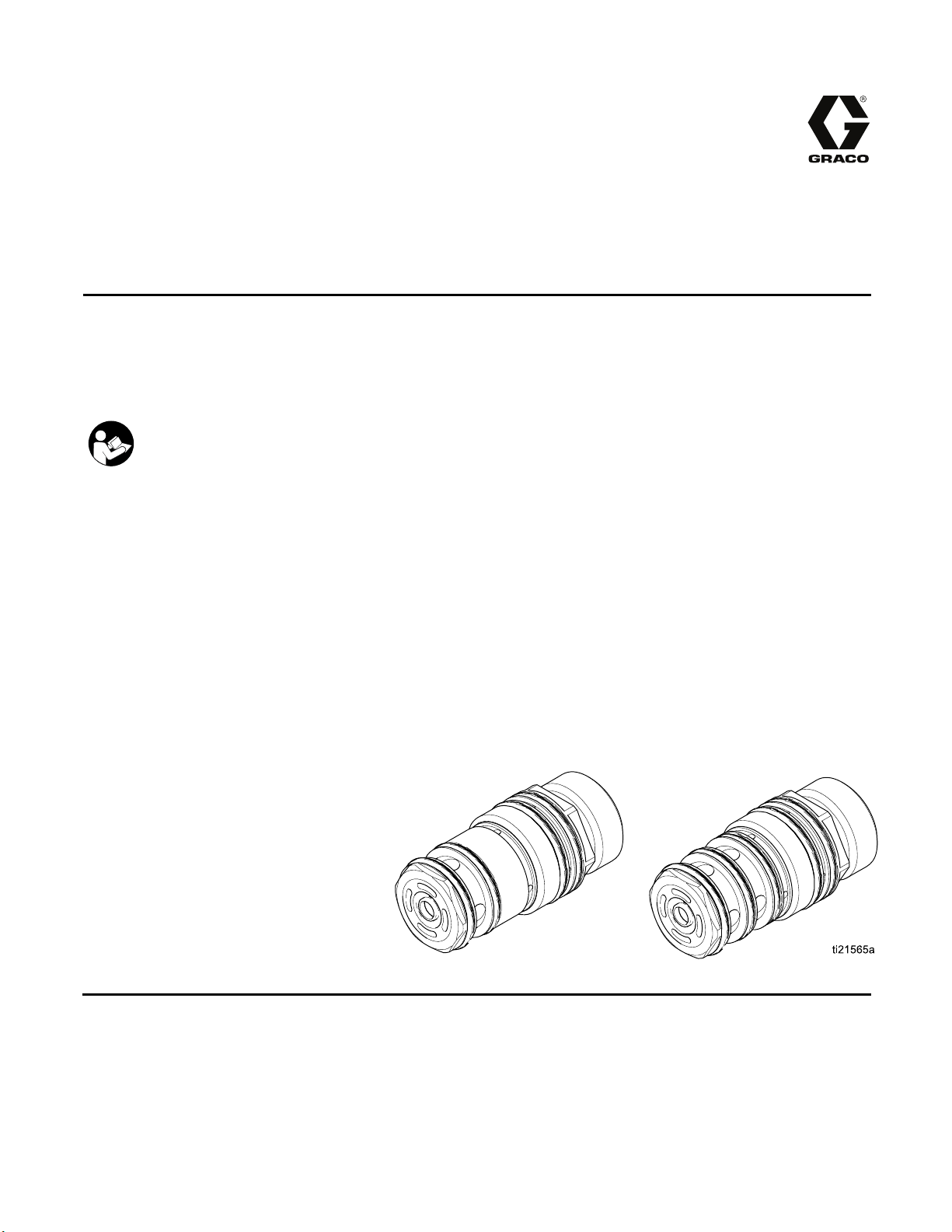
Color/Catalyst Dispense
332454B
Valves
To dispense color, catalyst, and solvent in a ProMix® PD2K Electronic Proportioning System with the
color change option.
For professional use only.
Important Safety Instructions
Read all warnings and instructions in your color change kit manual
and PD2K proportioner manual. Save these instructions.
See page 3 for model part numbers
and maximum working pressures.
EN
PROVEN QUALITY. LEADING TECHNOLOGY.
Page 2

Contents
Related Manuals ................................................ 2
Models............................................................... 2
Repair................................................................ 3
Disassembly................................................ 3
Reassembly ................................................ 4
Parts.................................................................. 5
Related Manuals
Manual No. Description
3A2800 PD2K Proportioner Repair-Parts
Manual, Manual Systems
332457 PD2K Proportioner Installation
Manual, Manual Systems
332562
3A2801
PD2K Proportioner Operation
Manual, Manual Systems
Mix Manifold Instructions-Parts
Manual
Low Pressure Valve Parts ............................ 5
High Pressure Valve Parts............................ 6
O-Ring Size Guide ....................................... 7
Technical Data ...................................................9
Graco Standard Warranty.................................... 10
Manual No. Description
332339 Pump Repair-Parts Manual
332455
332456 3rd and 4th Pump Kits
Color Change Kits InstructionsParts Manual
Instructions-Parts Manual
Models
Kit No.
24T441 A non-circulating 100 psi (0.7 MPa, 7.0 bar) 300 psi (2.068 MPa, 20.68bar)
24T442 A circulating
24T581 A non-circulating
24T582 A circulating
24T583 A non-circulating, acid
Series
Kit Description Maximum Air Working Pressure Maximum Fluid Working
Pressure
Low Pressure Valve Kits
100 psi (0.7 MPa, 7.0 bar) 300 psi (2.068 MPa, 20.68 bar)
High Pressure Valve Kits
100 psi (0.7 MPa, 7.0 bar) 1500 psi (10.34 MPa, 103.4 bar)
100 psi (0.7 MPa, 7.0 bar) 1500 psi (10.34 MPa, 103.4 bar)
100 psi (0.7 MPa, 7.0 bar) 1500 psi (10.34 MPa, 103.4 bar)
compatible
2
332454B
Page 3

Repair
Disassembly
Repair
1. Relieve the pressure as described in your PD2K
operation manual.
2. Remove the valve from the manifold as described
in your color change kit manual. Inspect the
111450 manifold o-ring.
3. Hold the seat body (2) steady with a box wrench.
Use a wrench on the flats of the piston body (5)
to unscrew it from the seat body.
4. Remove the spring (11).
NOTE: High pressure valves have two springs
(11 and 21).
5. Remove the two outer o-rings (16) and the inner
o-ring (20) from the piston body (5).
6. Using the 16N257 Tool (111, supplied with the
valve manifold kit), unscrew the valve seat (1)
from the seat body (2).
7. Unscrew the ball (3) from the shaft (4), using a
wrench on the flats of the ball.
8. Slide the piston and shaft assembly (4) out of the
seat housing (2). Remove the piston o-ring (18).
9. Using the 16N257 Tool (111), unscrew the
backup seal and washer (9) from the seat body
(2).
10. Remove the o-ring (19) from the seat body (2).
11. Using a small screwdriver, push the seal and
retainer (7) out of the seat body (2) from the
opposite end. Remove the o-ring (14) from the
seat body (2).
12. Remove the o-rings (15) from the seat body (2).
NOTE: Circulating valves have three o-rings (15);
non-circulating valves have two.
re 1 Remove Valve Seat
Figu
332454B 3
Page 4

Repair
Reassembly
1. Install the o-rings (15) on the seat body (2).
NOTE: Circulating valves have three o-rings (15);
non-circulating valves have two.
2. Lubricate the o-ring (14) and install it in the seat
body (2).
3. Lubricate the u-cup in the seal and retainer
assembly (7). Install in the seat body (2) with the
lips of the u-cup facing into the seat body.
4. Install the o-ring (19) in the seat body (2).
5. Using the 16N257 Tool (111), screw the backup
seal and washer (9) into the seat body (2).
Torque to 20 in-lb (2.2 N•m).
6. Install the piston o-ring (18) on the piston.
7. Lubricate the piston shaft (4) and slide it into the
seat body (2).
8. Apply medium strength (blue) thread sealant to
the ball (3). Using a wrench on the flats of the
ball, screw it onto the shaft (4). Torque to 5 in-lb
(0.5 N•m) maximum.
9. Lubricate the ball and inside surface of the seat
body (2). Using the 16N257 Tool (111), screw
the valve seat (1) into the seat body (2). Torque
to 20 in-lb (2.2 N•m).
10. Lubricate the o-ring (20) and install it in the piston
body (5).
11. Install the o-rings (16) on the piston body (5).
12. Lubricate the inside of the piston body (5) and
the piston o-ring (18).
13. Install the piston spring (11). On high pressure
valves only, install the second piston spring (21).
14. Screw the seat body (2) into the piston body (5).
Torque to 5 in-lb (0.5 N•m) maximum.
15. Lubricate the outer o-rings (15, 16).
16. Slide the assembled valve into the manifold, with
the seat body (2) facing into the manifold.
17.Returnthevalvetoservice.
ure 2 Valve Assembly (High Pressure Circulating
Fig
ve Shown)
Val
4
332454B
Page 5

Parts
Low Pressure Valve Parts
Part No. 24T442 Low Pressure Circulating Valve (shown)
Part No. 24T441 Low Pressure Non-Circulating Valve (see detail at upper left)
Parts
Ref. No
1
3 16N247 BALL, valve; stainless steel 1
4 24T530
5
7
9 24T534
11 16W502
14*
15*
16*
18*
19
20*
. Part No. Description
16N244
16N245
16N275
16N252
24T533
113746
117559
117559
121370
116768
* 117517
16D530
SEAT, v
BODY,
BODY,
ASSEM
BODY
SEAL
BACK
SPRI
O-RI
O-R
O-R
O-R
O-R
O-
O-
alve; PEEK 1
seat, circulating; PEEK; 24T442 only 12
seat, non-circulating; PEEK; 24T441 only 1
BLY, piston and shaft; stainless steel, aluminum 1
, piston; aluminum 1
AND RETAINER; UHMWPE and PEEK 1
UP SEAL AND WASHER; UHMWPE and aluminum 1
NG, piston 1
NG; chemically resistant 1
ING; chemically resistant; 24T442 only 3
ING; chemically resistant; 24T441 only 2
ING; chemically resistant 2
ING; chemically resistant 1
RING; chemically resistant 1
RING; chemically resistant 1
Qty
* Parts included in O-ring Kit 24T847 (purchase separately). Kit includes 3 of item 15, and also includes a
manifold o-ring 111450. See Kit 24T847, for Low Pressure Valves, page 7 .
332454B 5
Page 6

Parts
High Pressure Valve Parts
PartNo.24T582HighPressureCirculatingValve(shown)
PartNo. 24T581HighPressureNon-CirculatingValve(seedetailatupperleft)
Part No. 24T583 High Pressure Non-Circulating Acid
Compatible Valve (see detail at upper left)
Ref. No. Part No. Description Qty
1 16W158 SEAT, valve; stainless steel 1
16N266 BODY, seat, circulating; stainless steel; 24T582 only 12
16N276 BODY, seat, non-circulating; stainless steel; 24T581 and 24T583 only 1
24T205 BALL, valve; stainless steel; 24T583 only 13
24T204 BALL, valve; carbide; 24T581 and 24T582 only 1
4 24T735 ASSEMBLY, piston and shaft; stainless steel, aluminum 1
5
7
9 24T534 BACKUP SEAL AND WASHER; UHMWPE and aluminum 1
11 16N254 SPRING, piston, small 1
14* 113746 O-RING; chemically resistant 1
16* 122134 O-RING; chemically resistant 2
18* 16V699 O-RING; chemically resistant 1
19* 117517 O-RING; chemically resistant 1
20*
21
16N267 BODY, piston; aluminum 1
24T533 SEAL AND RETAINER; UHMWPE and PEEK 1
16N901 O-RING; chemically resistant; 24T582 only 315*
16N901 O-RING; chemically resistant; 24T581 and 24T583 only 2
16D531 O-RING; chemically resistant 1
16N270 SPRING, piston, large 1
* Parts included in O-ring Kit 24T848 (purchase separately). Kit includes 3ofitem15,andalsoincludesa
manifold o-ring 111450. See Kit 24T848, for High Pressure Valves, page 8 .
6 332454B
Page 7

O-Ring Size Guide
The following illustrations show the valve o-rings at actual size. See the Parts drawings for locations of
the o-rings.
TIP: Some o-rings are close in size. Stack on a bench to differentiate.
Kit 24T847, for Low Pressure Valves
Parts
Figure 3 K
Ref. No. Part No. Nominal Size OD, in. (mm) Qty
———
14* 113746 014 0.6 (16) 1
15*
16*
18*
19*
20*
it 24T847 O-Ring Sizes
111450 010 0.4 (10) 1
117559 020
121370 022
116768 016
117517 015
16D530 018
1 (25)
1.1 (29)
0.75 (19)
0.7 (18)
0.9 (22)
3
2
1
1
1
332454B
7
Page 8

Parts
Kit 24T848, for High Pressure Valves
Figure 4 Kit 24T848 O-Ring Sizes
Ref. No.
———
14*
15*
16* 12213
18* 16V699 021 1.06 (27) 1
19* 117517 015 0.7 (18) 1
20*
Part No.
111450 010
113746 014
16N901 025
4
16D531 023
Nominal Size OD, in. (mm) Qty
027 1.4 (37) 2
0.4 (10)
0.6 (16)
1.3 (33)
30) 1
1.2 (
1
1
3
8 332454B
Page 9

Technical Data
Technical Data
Color Change Kits U.S.
Maximum fluid working
pressure:
Low pressure valves 300 psi 2.1 MPa, 21 bar
High pressure valves 1500 psi 10.5 MPa, 105 bar
Maximum working air
pressure:
Air supply: 85–100 psi 0.6–0.7 MPa, 6.0–7.0 bar
Viscosity range of fluid:
Weight
24T441 low pressure
non-circulating valve
24T442 low pressure
circulating valve
24T581 and 24T583 high
pressure non-circulating
valves
24T582 high pressure
circulating valve
Wetted parts:
24T441 and 24T442 low
pressure valves
24T581 and 24T582 high
pressure valves
24T583 high pressure
acid compatible valve
PEEK, 301 and 17–4 stainless steel, UHMWPE, chemically resistant o-rings
PEEK, 301, 316, and 17–4 stainless steel, UHMWPE, chemically resistant o-rings
100 psi 0.7 MPa, 7.0 bar
20–5000 centipoise
55 g
53 g
248 g
227 g
PEEK, 301 and 17–4 stainless steel, UHMWPE, chemically
resistant o-rings, carbide
Metric
332454B 9
Page 10

Graco Standard Warranty
Graco warrants all equipment referenced in this document which is manufactured by Graco and bearing its
name to be free from defects in material and workmanship on the date of sale to the original purchaser for use.
With the exception of any special, extended, or limited warranty published by Graco, Graco will, for a period of
twelve months from the date of sale, repair or replace any part of the equipment determined by Graco to be
defective. This warranty applies only when the equipment is installed, operated and maintained in accordance
with Graco’s written recommendations.
This warranty does not cover, and Graco shall not be liable for general wear and tear, or any malfunction,
damage or wear caused by faulty installation, misapplication, abrasion, corrosion, inadequate or improper
maintenance, negligence, accident, tampering, or substitution of non-Graco component parts. Nor shall Graco
be liable for malfunction, damage or wear caused by the incompatibility of Graco equipment with structures,
accessories, equipment or materials not supplied by Graco, or the improper design, manufacture, installation,
operation or maintenance of structures, accessories, equipment or materials not supplied by Graco.
This warranty is conditioned upon the prepaid return of the equipment claimed to be defective to an authorized
Graco distributor for verification of the claimed defect. If the claimed defect is verified, Graco will repair or replace
free of charge any defective parts. The equipment will be returned to the original purchaser transportation
prepaid. If inspection of the equipment does not disclose any defect in material or workmanship, repairs will be
made at a reasonable charge, which charges may include the costs of parts, labor, and transportation.
THIS WARRANTY IS EXCLUSIVE, AND IS IN LIEU OF ANY OTHER WARRANTIES, EXPRESS OR IMPLIED,
INCLUDING BUT NOT LIMITED TO WARRANTY OF MERCHANTABILITY OR WARRANTY OF FITNESS
FOR A PARTICULAR PURPOSE.
Graco’s sole obligation and buyer’s sole remedy for any breach of warranty shall be as set forth above. The
buyer agrees that no other remedy (including, but not limited to, incidental or consequential damages for lost
profits, lost sales, injury to person or property, or any other incidental or consequential loss) shall be available.
Any action for breach of warranty must be brought within two (2) years of the date of sale.
GRACO MAKES NO WARRANTY, AND DISCLAIMS ALL IMPLIED WARRANTIES OF MERCHANTABILITY
AND FITNESS FOR A PARTICULAR PURPOSE, IN CONNECTION WITH ACCESSORIES, EQUIPMENT,
MATERIALS OR COMPONENTS SOLD BUT NOT MANUFACTURED BY GRACO. These items sold, but not
manufactured by Graco (such as electric motors,
their manufacturer. Graco will provide purchaser with reasonable assistance in making any claim for breach of
these warranties.
In no event will Graco be liable for indirect, incidental, special or consequential damages resulting from Graco
supplying equipment hereunder, or the furnishing, performance, or use of any products or other goods sold
hereto, whether due to a breach of contract, breach of warranty, the negligence of Graco, or otherwise.
FOR GRACO CANADA CUSTOMERS
The Parties acknowledge that they have required that the present document, as well as all documents, notices
and legal proceedings entered into, given or instituted pursuant hereto or relating directly or indirectly hereto, be
drawn up in English. Les parties reconnaissent avoir convenu que la rédaction du présente document sera en
Anglais, ainsi que tous documents, avis et procédures judiciaires exécutés, donnés ou intentés, à la suite de ou
en rapport, directement ou indirectement, avec les procédures concernées.
switches, hose, etc.), are subject to the warranty, if any, of
Graco Information
For the latest information about Graco products, visit www.graco.com.
To place an order, contact your Graco Distributor or call to identify the nearest distributor.
Phone: 612-623-6921 or Toll Free: 1-800-328-0211 Fax: 612-378-3505
All written and visual data contained in this document reflects the latest product information available at the time of publication.
raco reserves the right to make changes at any time without notice.
G
For patent information, see www.graco.com/patents.
Original Instructions. This manual contains English. MM 332454
Graco Headquarters: Minneapolis
International Offices: Belgium, China, Japan, Korea
GRACO INC. AND SUBSIDIARIES • P.O. BOX 1441 • MINNEAPOLIS MN 55440-1441 • USA
Copyright 2013, Graco Inc. All Graco manufacturing locations are registered to ISO 9001.
www.graco.com
Revised October 2013
 Loading...