

Page 1

Kit Instructions
ExactaBlend™ AGP Advanced Glazing Proportioner
332453C
Accessory Kits
For dispensing two component silicone and urethane materials.
For professional use only.
Not approved for use in explosive atmospheres or hazardous locations.
Refer to ExactaBlend AGP Advanced Glazing Proportioner, Setup-Operation manual for maximum working pressure
and model information.
Important Safety Instructions
Read all warnings and instructions in this
manual and the ExactaBlend AGP Advanced
Glazing Proportioner, Setup-Operation manual. Save all instructions.
EN
S100 Shown
24r809
Page 2

Related Manuals
Related Manuals
Refer to ExactaBlend AGP Advanced Glazing Proportioner, Setup-Operation manual for the complete list of
related manuals.
Contents
Related Manuals . . . . . . . . . . . . . . . . . . . . . . . . . . . 2
Contents . . . . . . . . . . . . . . . . . . . . . . . . . . . . . . . . . . 2
Installation . . . . . . . . . . . . . . . . . . . . . . . . . . . . . . . . 3
Light Tower, 24R824 . . . . . . . . . . . . . . . . . . . . . . 3
S100 Low Level Sensors, 24R935 . . . . . . . . . . . 4
Calibration Check Assembly, 24R777 . . . . . . . . . 6
USB Kit, 24R936 . . . . . . . . . . . . . . . . . . . . . . . . . 7
Caster Kit, 24T091 . . . . . . . . . . . . . . . . . . . . . . . 8
Operation . . . . . . . . . . . . . . . . . . . . . . . . . . . . . . . . . 9
USB Kit, 24R936 . . . . . . . . . . . . . . . . . . . . . . . . . 9
Troubleshooting . . . . . . . . . . . . . . . . . . . . . . . . . . . 10
Parts . . . . . . . . . . . . . . . . . . . . . . . . . . . . . . . . . . . . 12
Light Tower, 24R824 . . . . . . . . . . . . . . . . . . . . . 12
S100 Low Level Sensors, 24R935 . . . . . . . . . . 13
Calibration Check Assembly, 24R777 . . . . . . . . 14
Calibration Check Module . . . . . . . . . . . . . . . . . 15
USB Kit, 24R936 . . . . . . . . . . . . . . . . . . . . . . . . 16
Caster Kit, 24T091 . . . . . . . . . . . . . . . . . . . . . . 17
Graco Standard Warranty . . . . . . . . . . . . . . . . . . . 18
Graco Information . . . . . . . . . . . . . . . . . . . . . . . . . 18
2 332453C
Page 3

Installation
Installation
Light Tower, 24R824
1. Perform the Shutdown procedure in the ExactaBlend AGP Advanced Glazing Proportioner,
Setup-Operation manual.
2. Remove the rear nut that secures the fluid plate.
NOTICE
To avoid machine damage or injury, do not remove
both bolts.
4. Mount the light tower to the bracket. Hand tighten
the light tower nut.
5. Connect the cable from the light tower to port 5
located on the Fluid Control Module (FCM).
3. Fasten the light tower bracket to the boom assembly. Torque the nut to 24 ft-lb (33 N•m).
332453C 3
Page 4

Installation
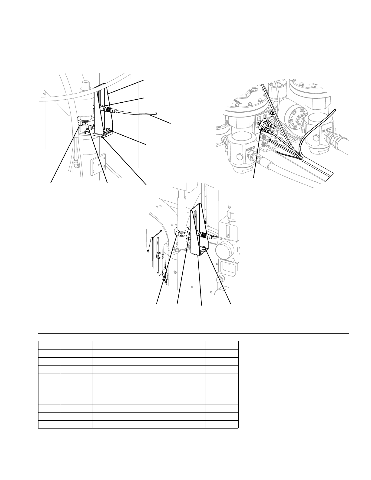
S100 Low Level Sensors, 24R935
1. Perform the Shutdown procedure in the Exact-
aBlend AGP Advanced Glazing Proportioner,
Setup-Operation manual.
2. Remove the air shut off valve cable from port 1
located on the Fluid Control Module (FCM).
3. Install the splitter into port 1.
6. Mount the sensor to the bracket.
x 2
7. Attach the bracket to the electrical enclosure for the
base ram. Torque the bolts to 5.1 ft-lb (6.9 N•m).
4. Install the air shut off valve cable and the low level
cable end labeled “J1B” into the splitter.
5. Route the low level cable along the boom. Follow
the air hoses and electrical lines that are installed.
8. Attach the bracket to the pump mast for the catalyst
ram. Torque the bolts to 5.1 ft-lb (6.9 N•m).
4 332453C
Page 5

Installation
9. Install a collar on the mast shaft for both chemical
rams.
10. Connect the cable end labeled “J1BA” to the base
sensor.
11. Connect the cable end labeled “J1BB” to the catalyst sensor.
12. Route and secure access cable so it will not be
damaged during normal machine operation.
13. Turn the power on at the electrical enclosure.
15. Adjust the sensor until it senses the collar. A light
will aluminate on the sensor to visually show it is
activated.
16. Tighten the sensor to its current position.
17. Adjust the collar on the shaft to the desired height
and tighten. The placement of the collar will determine when the machine will recognize an empty
drum.
18. Repeat steps 14 through 17 for the other chemical
sensor.
14. Slide the collar so it is at the level of the sensor.
19. Navigate to the Setup Screen 1 on the Display
Module (DM) and activate the low level sensor
option.
332453C 5
Page 6

Installation
Calibration Check Assembly, 24R777
1. Perform the Shutdown procedure in the Exact-
aBlend AGP Advanced Glazing Proportioner,
Setup-Operation manual.
2. Install the hose clamps onto the boom assembly.
Hand tighten all hose clamps. Refer to Calibration
Check Assembly, 24R777, page 14, for correct
screw locations.
NOTE: The base material tube is 0.5 in. (1.3 cm) in
diameter. Verify the hose clamps are installed on the
correct side of the boom assembly.
4. Install the tube fittings. Tighten the fittings to prevent
leaking.
5. Install the material tube lines onto the boom assembly. Tighten all fittings to prevent leaking.
3. Remove the pressure gauges and fittings.
6. Install the check valve assembly onto the tube lines.
Tighten all fittings to prevent leaking.
6 332453C
Page 7

Installation
USB Kit, 24R936
1. Perform the Shutdown procedure in the ExactaBlend AGP Advanced Glazing Proportioner,
Setup-Operation manual.
2. Mount the USB Module to the side of the electrical
enclosure. Torque the bolts to 2.6 ft-lb (3.5 N•m).
3. Connect the adapter to the USB Module. Connect
the CAN cable to the adapter. Route the CAN cable
along the boom. Follow the air hoses and electrical
lines that are installed.
4. Connect the CAN cable to the Fluid Control Module
(FCM).
5. Install the software upgrade token (16V853) into the
Display Module (DM) and cycle the power. Refer to
the Graco Control Architecture
ming manual for more details.
6. Install the software upgrade token (16V853) into the
USB module and cycle the power.
7. Refer to the ExactaBlend AGP Advanced Glazing
Proportioner, Setup-Operations manual for screen
details.
™
Module Program-
332453C 7
Page 8

Installation
Caster Kit, 24T091
1. Mount the caster to the bracket. Apply medium
strength thread locker to the threads. Torque the
fasteners to 21 ft-lb (29 N•m).
x 4
2. Lift the machine until it is 3 in. (8 cm) off of the
ground.
NOTICE
Injury may occur if the machine is lifted and not
secured to prevent falling. Rest the machine on
stands or blocks while installing the caster kit.
3. Fasten the bracket to the base frame. Apply medium
strength thread locker to the threads. Torque the
bolts to 30 ft-lb (40 N•m).
x 4
4. Lower the machine.
8 332453C
Page 9

Operation
Operation
USB Kit, 24R936
When a USB memory device is inserted into the USB
module, a status icon will appear on the DM screen. The
icon will appear as shown when downloading is complete.
Data
Error Codes
This file shows the date, time, error/event codes, and the
status of the codes. Refer to DM Error Codes within the
ExactaBlend AGP Advanced Glazing Proportioner,
Setup-Operation manual for code information.
NOTE: The codes will have the following for the status
column:
Run Data
This file shows the date, time, target ratio, actual ratio,
average flow rate, and both pump A and pump B chemical dispenses. All chemical dispense values are shown
in kilograms. The information is recorded at 5 second
intervals.
NOTE: The data is recorded only when the system is in
the “OK” state and during normal run mode dispensing.
Software Data
This file shows the date, time, part number, and software versions currently installed on the machine.
NOTE: The file will only show the information when the
download depth is set to “0”.
“0” - Error/event was generated
“1” - Machine acknowledged the error/event. There is no
user acknowledgement required.
“2” - User acknowledged the error/event.
332453C 9
Page 10

Troubleshooting
Troubleshooting
Problem Cause Solution
1. Follow Pressure Relief Procedure in the Exact-
aBlend AGP Advanced Glazing Proportioner,
Setup-Operation manual before checking or repairing gun.
2. Check all possible problems and causes before disassembling gun.
Light Tower
Light does not blink green, red, and
off in sequence when the machine
is first turned on.
The sensor does not activate. The low level sensor option has not
Screen 4 does not show the USB
option.
Bad connection or cable Ensure cable is connected or
Bad light stack. Replace light stack.
S100 Low Level Sensors
been activated on the DM.
The sensor has not been mounted
correctly.
The collar has been installed too
high on the shaft.
Bad connection or cable Ensure cable is connected or
Bad sensor Replace sensor.
USB Kit
Bad connection or cable. Ensure cable is connected or
Bad GCA components. Replace the GCA components.
replace the cable.
Navigate to Screen 1 and activate
the low level sensor option.
Adjust the sensor until it is activated
by the collar.
Lower the collar until the sensor is
activated.
replace the cable.
replace the cable.
10 332453C
Page 11

Troubleshooting
332453C 11
Page 12

Parts
Parts
Light Tower, 24R824
3
2
FIG. 1: Light Tower
Ref Part Description Quantity
1 --- BRACKET, tower, light, 30mm 1
2 127187 LIGHT, tower, 30mm, red / green / alarm 1
3 127184 HARNESS, m12xm12 1
--- Not available for individual sale.
1
12 332453C
Page 13
S100 Low Level Sensors, 24R935
102
106
109
103,
105
Parts
101
FIG. 2: Low Level Sensors
Ref Part Description Quantity
101 --- BRACKET, sensor, level, catalyst 1
102 --- BRACKET, sensor, low/empty 2
103 --- WASHER, lock, 1/4 6
104 --- SCREW, cap, socket head, 1/4-20x5/8 2
105 --- SCREW, socket head, M6-1x16mm 4
106 122716 SENSOR, inductive, m12 2
107 127140 COLLAR, clamp, 1-3/8 id, 2piece 1
108 127141 COLLAR, clamp, 1 id, 2piece 1
109 127137 HARNESS, splitter, m12, 5pin 1
110 126520 CONNECTOR, splitter, m12 1
103,
105
101
108 106 102 103,
110
105
--- Not available for individual sale.
332453C 13
Page 14

Parts
Calibration Check Assembly, 24R777
208,
211,
223
213
214
212
208,
211,
223
216
217
209,
210,
211
FIG. 3: Calibration Check Assembly
Ref Part Description Quantity
201 --- MODULE, ratio check, 1
204 127071 FITTING, flareless, 1/2 npt x 1/2 tube 1
206 127070 FITTING, flareless, 1/4 npt x 1/4 tube 1
208 126691 CLAMP, 1/2 in. od hose 3
209 126682 CLAMP, 1/4 in. od hose 3
210 --- SCREW, cap, socket head, 1/4-20x3/4 4
211 122643 NUT, rail 8
212 16V586 TUBE, ratio, base, inlet 1
213 127102 FITTING, flareless, 1/2 tube x 1/2 tube 1
214 16V587 TUBE, ratio, base, outlet, 1/2 1
215 16V588 TUBE, ratio, catalyst, inlet, 1/4 1
216 127103 FITTING, flareless, 1/4 tube x 1/4 tube 1
217 16V589 TUBE, ratio, outlet, 1/4 1
218 16V356 PIN, restrictor, #1, 0.094 in. 1
219 16V357 PIN, restrictor, #3, 0.102 in. 1
220 16V359 PIN, restrictor, #2, 0.098 in. 1
222 --- SCREW, cap, socket head, 1/4-20x1-1/4 2
223 --- SCREW, cap, socket head, 1/4-20x1 6
--- Not available for individual sale.
208,
222
209,
223
201
218,
219,
220
209,
210,
211
204
215
206
14 332453C
Page 15

Calibration Check Module
306
302
301
307
309
Parts
1
305
1
303
304
1
303
313
301
1
307
1
308
312
FIG. 4: Calibration Check Module
Ref Part Description Quantity
301 215622 VALVE, ball 2
302 217562 LEVER, valve 1
303 104984 FITTING, tee, pipe 2
304 127070 FITTING, flareless, 1/4 npt x 1/4 tube 1
305 127051 FITTING, flareless, 1/4 npt x 1/2 tube 1
306 112941 GAUGE, pressure, fluid 2
307 16V360 HOUSING, restrictor, 1/4 npt 2
308 127324 FITTING, adapter, 1/4 npt x 04 jic 1
309 116704 ADAPTER, 9/16-18 jic x 1/4 npt 1
312 127325 FITTING, cap, 04 jic 1
313 127326 FITTING, cap, 06 jic 1
Apply sealant to pipe threads.
306
332453C 15
Page 16

Parts
USB Kit, 24R936
401,
402
FIG. 5: USB Kit
Ref Part Description Quantity
401 24T005 MODULE, GCA, cube 1
402 --- SCREW, socket head, 10-32x0.75 4
403 16T072 ADAPTER, cable, CAN, IS to non IS 1
404 120952 CABLE, CAN, female / female 4.0 meter 1
405 16V853 SOFTWARE, GCA 1
403
404
16 332453C
Page 17

Caster Kit, 24T091
1
Apply medium strength thread locker to threads.
2
Torque to 30 ft-lb (40 N•m).
3
Torque to 21 ft-lb (29 N•m).
Parts
504
2
1
501
506
3
1
505
FIG. 6: Caster Kit
Ref Part Description Quantity
501 --- BRACKET, caster 4
502 --- BOLT, carriage, M10-1.5x30mm 8
503 --- NUT, hex, flange, serrated, M10-1.5 8
504 --- SCREW, machine, hex, M10-1.5x25mm 4
502,
503
1
2
505 --- CASTER, swivel, brake 4
506 --- SCREW, cap, hex head, M8-1.25x16mm 16
--- Not available for individual sale.
332453C 17
Page 18

Graco Standard Warranty
Graco warrants all equipment referenced in this document which is manufactured by Graco and bearing its name to be free from defects in
material and workmanship on the date of sale to the original purchaser for use. With the exception of any special, extended, or limited warranty
published by Graco, Graco will, for a period of twelve months from the date of sale, repair or replace any part of the equipment determined by
Graco to be defective. This warranty applies only when the equipment is installed, operated and maintained in accordance with Graco’s written
recommendations.
This warranty does not cover, and Graco shall not be liable for general wear and tear, or any malfunction, damage or wear caused by faulty
installation, misapplication, abrasion, corrosion, inadequate or improper maintenance, negligence, accident, tampering, or substitution of
non-Graco component parts. Nor shall Graco be liable for malfunction, damage or wear caused by the incompatibility of Graco equipment with
structures, accessories, equipment or materials not supplied by Graco, or the improper design, manufacture, installation, operation or
maintenance of structures, accessories, equipment or materials not supplied by Graco.
This warranty is conditioned upon the prepaid return of the equipment claimed to be defective to an authorized Graco distributor for verification of
the claimed defect. If the claimed defect is verified, Graco will repair or replace free of charge any defective par ts. The equipment will be returned
to the original purchaser transportation prepaid. If inspection of the equipment does not disclose any defect in material or workmanship, repairs will
be made at a reasonable charge, which charges may include the costs of parts, labor, and transportation.
THIS WARRANTY IS EXCLUSIVE, AND IS IN LIEU OF ANY OTHER WARRANTIES, EXPRESS OR IMPLIED, INCLUDING BUT NOT LIMITED
TO WARRANTY OF MERCHANTABILITY OR WARRANTY OF FITNESS FOR A PARTICULAR PURPOSE.
Graco’s sole obligation and buyer’s sole remedy for any breach of warranty shall be as set forth above. The buyer agrees that no other remedy
(including, but not limited to, incidental or consequential damages for lost profits, lost sales, injury to person or property, or any other incidental or
consequential loss) shall be available. Any action for breach of warranty must be brought within two (2) years of the date of sale.
GRACO MAKES NO WARRANTY, AND DISCLAIMS ALL IMPLIED WARRANTIES OF MERCHANTABILITY AND FITNESS FOR A
PARTICULAR PURPOSE, IN CONNECTION WITH ACCESSORIES, EQUIPMENT, MATERIALS OR COMPONENTS SOLD BUT NOT
MANUFACTURED BY GRACO. These items sold, but not manufactured by Graco (such as electric motors, switches, hose, etc.), are subject to
the warranty, if any, of their manufacturer. Graco will provide purchaser with reasonable assistance in making any claim for breach of these
warranties.
In no event will Graco be liable for indirect, incidental, special or consequential damages resulting from Graco supplying equipment hereunder, or
the furnishing, performance, or use of any products or other goods sold hereto, whether due to a breach of contract, breach of warranty, the
negligence of Graco, or otherwise.
FOR GRACO CANADA CUSTOMERS
The Parties acknowledge that they have required that the present document, as well as all documents, notices and legal proceedings entered into,
given or instituted pursuant hereto or relating directly or indirectly hereto, be drawn up in English. Les parties reconnaissent avoir convenu que la
rédaction du présente document sera en Anglais, ainsi que tous documents, avis et procédures judiciaires exécutés, donnés ou intentés, à la suite
de ou en rapport, directement ou indirectement, avec les procédures concernées.
Graco Information
For the latest information about Graco products, visit www.graco.com.
TO PLACE AN ORDER, contact your Graco distributor or call to identify the nearest distributor.
Phone: 612-623-6921 or Toll Free: 1-800-746-1334 Fax: 330-966-3006
All written and visual data contained in this document reflects the latest product information available at the time of publication.
GRACO INC. AND SUBSIDIARIES • P.O. BOX 1441 • MINNEAPOLIS MN 55440-1441 • USA
Copyright 2013, Graco Inc. All Graco manufacturing locations are registered to ISO 9001.
Graco reserves the right to make changes at any time without notice.
For patent information, see www.graco.com/patents.
Original instructions. This manual contains English. MM 332453
Graco Headquarters: Minneapolis
International Offices: Belgium, China, Japan, Korea
www.graco.com
Revised January 2014
 Loading...