

Page 1
Instructions
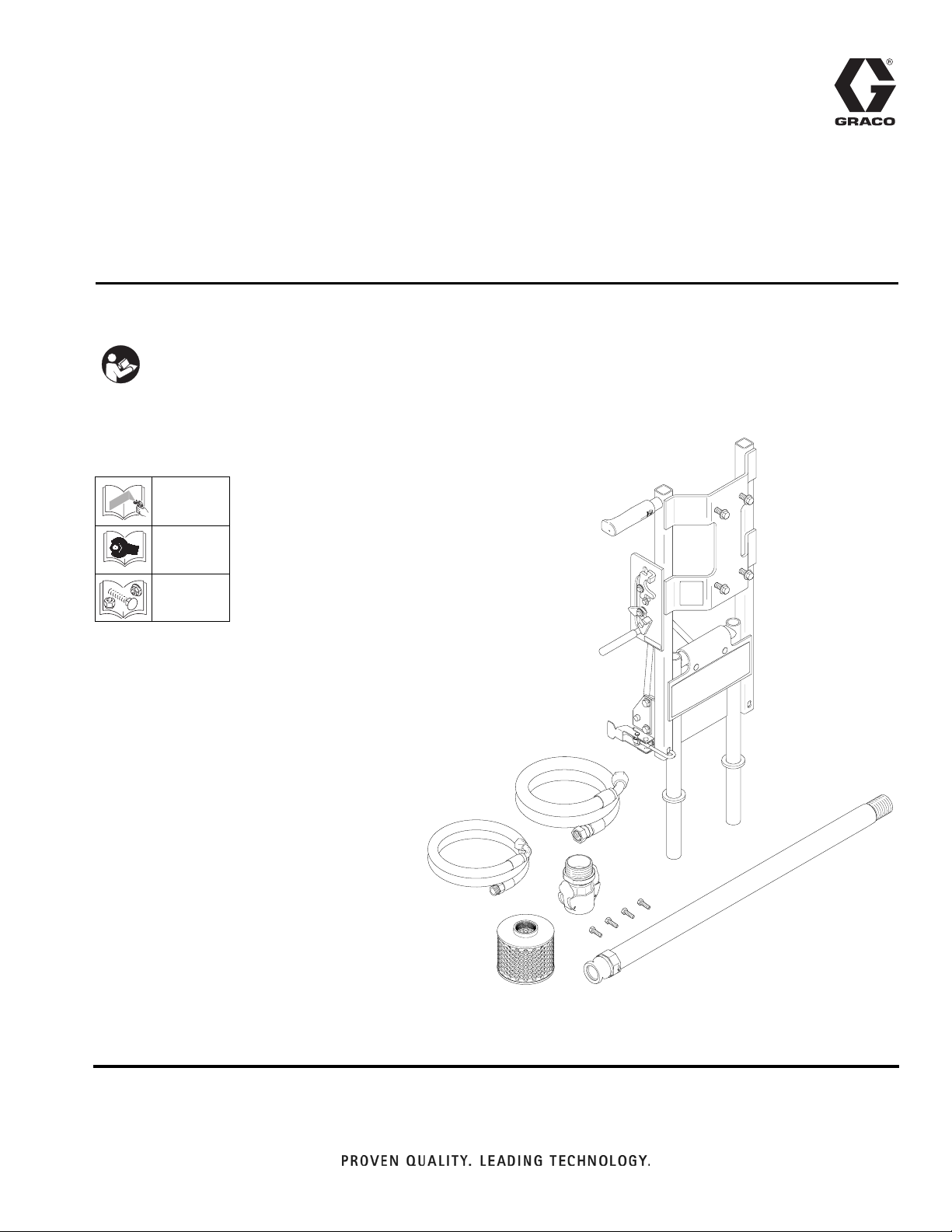
Direct Immersion Kit 16U764 for 2570
- For installation of tower/bracket -
IMPORTANT SAFETY INSTRUCTIONS
Read all warnings and instructions in this
manual. Save these instructions.
2570ES Models: Refer to operation manual below.
Before attempting to install kit,
follow Pressure Relief Procedure
332156
332157
332158
ES
332235A
EN
ti21168a
Page 2
Fixed Mounting (optional)
To prevent damaging the unit when transporting it
in a truck or on a trailer, Graco recommends fixed
mounting to the vehicle.
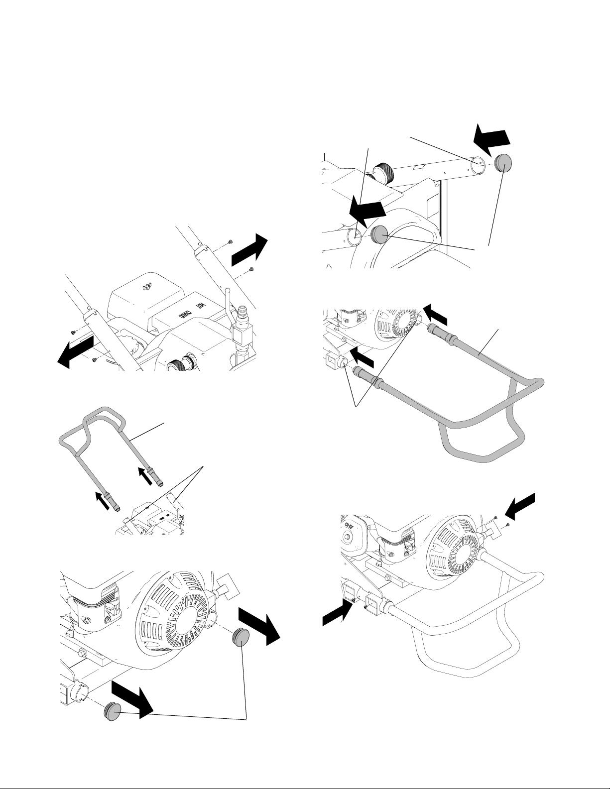
Repositioning Handle
Before you can secure the unit to a truck or trailer bed,
you must reposition the handle.
1. Remove four handle sleeve screws.
ti7649b
2. Pull handle out of upper frame handle tubes and
remove.
4. Insert plugs in upper frame handle tubes.
upper frame handle
tubes
plugs
ti7744b
5. Insert handle into lower frame tubes. Face hose
bracket down. Adjust to appropriate in/out location.
handle
handle
upper
frame
handle
tubes
ti7651b
3. Remove two frame tube plugs located behind
wheels.
lower frame tubes
ti7653b
6. Install four sleeve screws in lower frame tubes.
ti7652b
ti7650b
plugs
2 332235A
Page 3

Securing Unit to Vehicle Bed
For fixed mounting, fasten U-bolts over sprayer frame
as indicated in the following illustration.
Sprayer is a heavy piece of equipment. To avoid bodily
injury that could result from equipment moving when
transporting, secure sprayer to vehicle.
1. Reposition handle, steps 1-5, page 2.
2. Place U-bolts over sprayer frame and through holes
in vehicle bed. Place a washer and nut over bolt
end. Tighten nut securely.
Reposition Handle
U-bolts
U-bolts
332235A 3
Kit.jpg
Page 4

General Information
Pressure Relief Procedure
1. Engage trigger lock.
2. Set pump valve OFF.
3. Turn engine OFF.
4. Turn pressure to lowest setting.
5. Trigger gun to relieve pressure.
6. Turn Prime valve down.
Trigger Lock
Engage trigger lock when you stop spraying to prevent
gun from being accidentally triggered by hand or if
dropped or bumped.
4 332235A
Page 5

Removing Hydraulic Head and Pump
5. Remove four mounting bolts on pump assembly and
set assembly out of the way.
BURN HAZARD
Equipment surfaces and fluid that’s heated can
become very hot during operation. To avoid severe
burns, do not touch hot fluid or equipment. Wait until
equipment/fluid has cooled completely.
1. Follow Pressure Relief Procedure, page 4.
2. Allow unit to cool.
3. Remove two hydraulic lines from head and body.
hydraulic
lines
ti20953a
pump
assembly
bolts
ti7598a
4. Remove suction set from pump.
ti21178a
6. Remove two black plugs.
NOTE: Protect open hydraulic ports from debris and
contamination.
plugs
pump
suction
set
ti21180a
ti7599a
332235A 5
hydraulic
ports
Page 6

Installing Direct Immersion Kit
1. Install tower/bracket into frame holes.
tower
bracket
frame
ti7600b
holes
Pumping motion could result in bracket pulling out of
frame and cause serious injury. Always insert and
torque screws securely to insure this does not occur.
2. Install four retaining screws in frame to hold
tower/bracket in place. Torque to 165 +/- 10 in-lb
(13.8 ft-lb).
5. Torque bolts to 400 +/- 10 in-lb (33.3 ft-lb).
ti7603b
6. Install new, longer hydraulic lines (19, 20) from kit.
20
ti7604b
19
ti7601b
3. Install four bolts onto immersion kit.
ti20994a
4. Install pump assembly over four frame bolts.
7. To purge air from hydraulic lines, increase pressure
enough to start hydraulic motor stroking and allow
fluid to circulate for 15 seconds. Turn pressure
down, turn Prime valve horizontal (off).
+
ti7110c
ti7111b
ti7129b
-
pump
assembly
ti7602b
6 332235A
Page 7

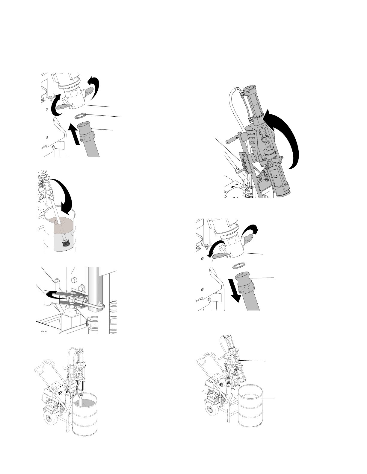
Using Direct Immersion
MOVING PARTS HAZARD
Moving parts can pinch or amputate fingers and other
body parts.
• Keep clear of moving parts.
• Do not operate equipment with protective guards
or covers removed.
• Pressurized equipment can start without warning.
Before checking, moving, or servicing equipment,
follow the Pressure Relief Procedure in this
manual. Disconnect power or air supply.
4. Unclamp and tilt tower/bracket back to 1st position.
clamp
1. Apply pipe thread sealant 119400 over male
threads on pump.
34
ti21170a
2. Apply pipe sealant to bushing (34).
3. Position 55-gallon drum under pump assembly.
pump
assembly
ti21181a
5. Lock clamp into 1st position.
1st position
6. Install strainer (23) to bottom of intake tube (24).
24
23
55-gallon
drum
ti7646a
ti21169a
332235A 7
Page 8
7. Install intake tube (24). Lock female hose adapter
(22) to hold intake tube securely in place. Verify
hose adapter gasket (22a) is in place.
22
22a
24
ti21172a
8. Lower intake tube into 55-gallon drum.
Changing Drums
1. Tilt tower/bracket back and clamp securely in 1st
position.
clamp
ti21181a
2. Unlock female hose adapter (22) and remove intake
tube (24).
ti21173a
9. Lock tower/bracket in place.
10. Ready to use.
22
24
ti21179a
3. Move sprayer/tower/bracket (unit) and align new
drum under pump assembly.
pump
assembly
drum
ti21183a
ti21177a
8 332235A
Page 9
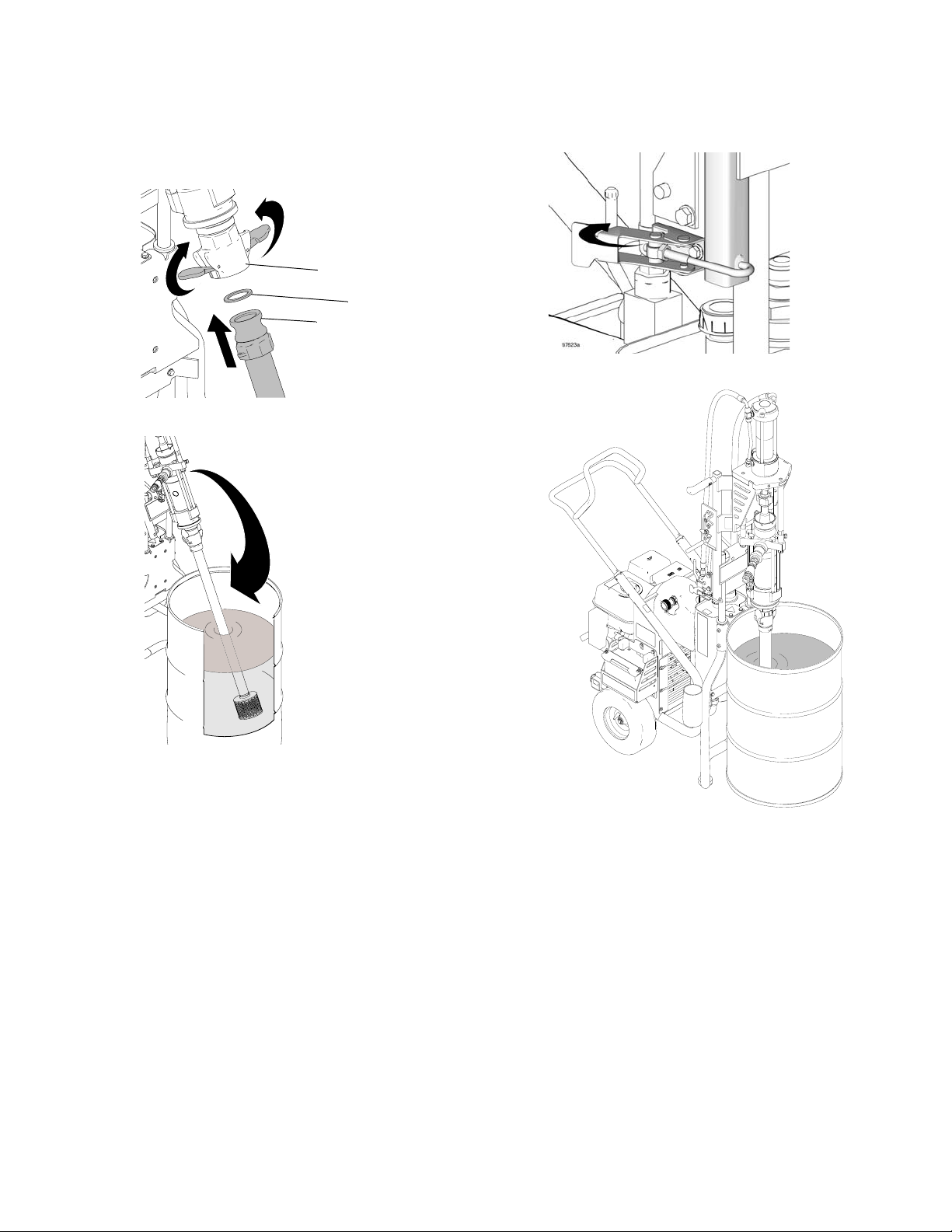
4. Ensure gasket (22a) is in place and install intake
tube (24). Lock female hose adapter (22) to hold
intake tube securely in place.
22
22a
24
ti21172
5. Lower intake tube into 55-gallon drum.
6. Lock tower/bracket in place.
7. Ready to use.
ti21173a
ti21177a
332235A 9
Page 10

Transporting Unit
NOTE:
When transporting unit securely tie down in vehicle or
follow instructions for fixed mounting to vehicle, page 2.
1. Unlock tower/bracket.
2. Tip tower/bracket back 90° to 2nd position for trans-
Do not transport unit with head in vertical position.
porting.
3. Lock in place.
2nd position
2nd
position
1st
position
ti21171a
10 332235A
Page 11

Parts
Parts
5
34
22
20
19
22a
24
14
13131313
1010
9
27
4
29
11
15
31
3
8
28
16
1717
6
77
ti21176a
1
23
Ref Part Description Qty
1 287897 SUPPORT, frame
2 287896 FRAME, 55 gallon lift
3 188622 SPACER
4 116630 SCREW
5 102040 NUT, lock, hex
6 15H478 PLATE, retainer
7 112395 SCREW, cap, flnghd
8 288037 BRACE, tilt, back
9 119872 SCREW, shoulder
10 120454 WASHER, flat
11 15H496 LATCH, liftkit, lower
12 15H495 LATCH, liftkit, upper
13 120226 SCREW, hex hd, flange
14 108063 GRIP, handle
15 114808 CAP, vinyl
16 195550 LATCH, adjustable
17 113796 SCREW, flanged, hex hd
18 114251 SCREW, cap, hex hd
2325232323
Ref Part Description Qty
19 15H265 HOSE, coupled
1
20 15H268 HOSE, coupled
1
21 120307 FITTING, hose adapter, male
2
22 120308 FITTING, hose adapter, female;
2
2
22a 120781 GASKET, hose adapter
1
23 187119 STRAINER
2
24 16U362 TUBE, inlet
1
25 119400 SEALANT
3
27▲ 15H619 LABEL, warning
4
28 15H618 LABEL
1
29 192840 LABEL
1
34 16U361 BUSHING
4
Includes 22a
1
▲
1
1
Replacement Warning labels, tags, and cards are
available at no cost.
2
4
332235A 11
1
1
1
1
1
1
1
2
1
1
Page 12

Parts
Dimensions
All dimensions are in inches
80
59
ti21174a
41
ti21175a
78
12 332235A
Page 13

Notes
Notes
332235A 13
Page 14

Graco Standard Warranty
Graco warrants all equipment referenced in this document which is manufactured by Graco and bearing its name to be free from defects in
material and workmanship on the date of sale to the original purchaser for use. With the exception of any special, extended, or limited warranty
published by Graco, Graco will, for a period of twelve months from the date of sale, repair or replace any part of the equipment determined by
Graco to be defective. This warranty applies only when the equipment is installed, operated and maintained in accordance with Graco’s written
recommendations.
This warranty does not cover, and Graco shall not be liable for general wear and tear, or any malfunction, damage or wear caused by faulty
installation, misapplication, abrasion, corrosion, inadequate or improper maintenance, negligence, accident, tampering, or substitution of
non-Graco component parts. Nor shall Graco be liable for malfunction, damage or wear caused by the incompatibility of Graco equipment with
structures, accessories, equipment or materials not supplied by Graco, or the improper design, manufacture, installation, operation or
maintenance of structures, accessories, equipment or materials not supplied by Graco.
This warranty is conditioned upon the prepaid return of the equipment claimed to be defective to an authorized Graco distributor for verification of
the claimed defect. If the claimed defect is verified, Graco will repair or replace free of charge any defective parts. The equipment will be returned
to the original purchaser transportation prepaid. If inspection of the equipment does not disclose any defect in material or workmanship, repairs
will be made at a reasonable charge, which charges may include the costs of parts, labor, and transportation.
THIS WARRANTY IS EXCLUSIVE, AND IS IN LIEU OF ANY OTHER WARRANTIES, EXPRESS OR IMPLIED, INCLUDING BUT NOT LIMITED
TO WARRANTY OF MERCHANTABILITY OR WARRANTY OF FITNESS FOR A PARTICULAR PURPOSE
Graco’s sole obligation and buyer’s sole remedy for any breach of warranty shall be as set forth above. The buyer agrees that no other remedy
(including, but not limited to, incidental or consequential damages for lost profits, lost sales, injury to person or property, or any other incidental or
consequential loss) shall be available. Any action for breach of warranty must be brought within two (2) years of the date of sale.
GRACO MAKES NO WARRANTY, AND DISCLAIMS ALL IMPLIED WARRANTIES OF MERCHANTABILITY AND FITNESS FOR A
PARTICULAR PURPOSE, IN CONNECTION WITH ACCESSORIES, EQUIPMENT, MATERIALS OR COMPONENTS SOLD BUT NOT
MANUFACTURED BY GRACO
the warranty, if any, of their manufacturer. Graco will provide purchaser with reasonable assistance in making any claim for breach of these
warranties.
In no event will Graco be liable for indirect, incidental, special or consequential damages resulting from Graco supplying equipment hereunder, or
the furnishing, performance, or use of any products or other goods sold hereto, whether due to a breach of contract, breach of warranty, the
negligence of Graco, or otherwise.
FOR GRACO CANADA CUSTOMERS
The Parties acknowledge that they have required that the present document, as well as all documents, notices and legal proceedings entered into,
given or instituted pursuant hereto or relating directly or indirectly hereto, be drawn up in English. Les parties reconnaissent avoir convenu que la
rédaction du présente document sera en Anglais, ainsi que tous documents, avis et procédures judiciaires exécutés, donnés ou intentés, à la suite
de ou en rapport, directement ou indirectement, avec les procédures concernées.
. These items sold, but not manufactured by Graco (such as electric motors, switches, hose, etc.), are subject to
.
Graco Information
For the latest information about Graco products, visit www.graco.com.
TO PLACE AN ORDER, contact your Graco distributor or call 1-800-690-2894 to identify the nearest distributor.
All written and visual data contained in this document reflects the latest product information available at the time of publication.
GRACO INC. AND SUBSIDIARIES • P.O. BOX 1441 • MINNEAPOLIS MN 55440-1441 • USA
Copyright 2012, Graco Inc. All Graco manufacturing locations are registered to ISO 9001.
Graco reserves the right to make changes at any time without notice.
For patent information, see www.graco.com/patents.
Original instructions.
This manual contains English. MM 332235
Graco Headquarters: Minneapolis
International Offices: Belgium, China, Japan, Korea
www.graco.com
Revised January 2013
 Loading...